Embed Size (px)
Citation preview
AFC Finishing Systems Leading the way since 1967
Operation & Maintenance Manual
Built in America, Supported with Integrity
.
Copyright © 2004 by AFC Finishing Systems All rights reserved. No part of this publication may be reproduced, stored in a retrieval system, or transmitted, in any form or by any means, electronic, mechanical, photocopying, or otherwise, without the prior written permission of AFC Finishing Systems.
Disclaimer of Liability AFC Finishing Systems has used its best efforts in preparing this manual and the information contained within. These efforts include testing, checking, and reviewing the functionality of the information. Because of the diversity and special individual customization of our spray booths and spray equipment, we cannot guarantee full agreement. However, the data contained within this manual is reviewed on a regular basis and any necessary correction will be included in subsequent editions. Any suggestions for improvement are welcome.
Trademarks AFC, AFC, Inc., AFC Finishing Systems, and Air Filtration Company are trademarks of AFC Finishing Systems. All other trademark symbols and names are registered trademarks of their respective companies. They are included as a benefit to the respective trademark owners only and are included with no intention of infringing on those trademarks.
AFC Finishing Systems 250 Airport Parkway Oroville, California 95965 Phone: (800) 331-7744 Fax: (530) 533-0179 Email: [email protected] Web: http://www.afc-ca.com
i
Introduction This manual is intended for the initial setup of the electrical and control systems of paint spray booths and how to operate and maintain paint spray booths only. Please refer to the booth installation instruction that comes with your paint spray booth for sheet metal installation. Electrical power to each system, fire suppression system and gas plumbing are also required and must be installed by qualified local contractor(s) prior to doing initial setup. Information on the Power Flame burner is shipped with the burner. Additional information on the Power Flame burner may be obtained from Power Flame at: Power Flame Incorporated 2001 South 21st Street Parsons, KS 67357 (602)421-0480 (602)421-0948 (fax) http://www.power-flame.com email: [email protected] AFC Finishing Systems offers free telephone support eight hours a day, five days a week from 8:00 A.M to 5:00 P.M. PST, Monday through Friday. We can be reached at our toll-free number: (800) 331-7744. Supports and General information are also available online at our web site, http://www.afc-ca.com.

Content
ii
Table of Content
1. Initial Start-up 1.0 Safety Precautions……………..………………………………………………………… 1-2 1.1 Initial Start-up Procedure………………………………………………………………… 1-2 1.2 Power Flame Burner Start-up Procedure……………………………………………… 1-4 1.3 Full Operation Test……………………………………………………………………….. 1-7
2. Operation 2.0 Operator Pre-start………………………………………………………………………… 2-2 2.1 Start-up, Shut-down, and Post Shut-down Procedures………………………………. 2-2 2.2 Normal Operations……………………………………………………………………….. 2-4 2.3 Emergency Operations…………………………………………………………………… 2-4
3. Maintenance 3.0 Operator Service Requirement………………………………………………………….. 3-2 3.1 Preventive Maintenance…………………………………………………………………. 3-2 3.2 Other Maintenance……………………………………………………………………….. 3-3 3.3 Troubleshooting Guides………………………………………………………………….. 3-4
4. Appendices 4.0 General Burner Information………………………………………………………………. 4-2 4.1 Spare parts and supply Lists…………………………………………………………….. 4-14 4.2 Warranty Information………………………………………………………………………. 4-14
.
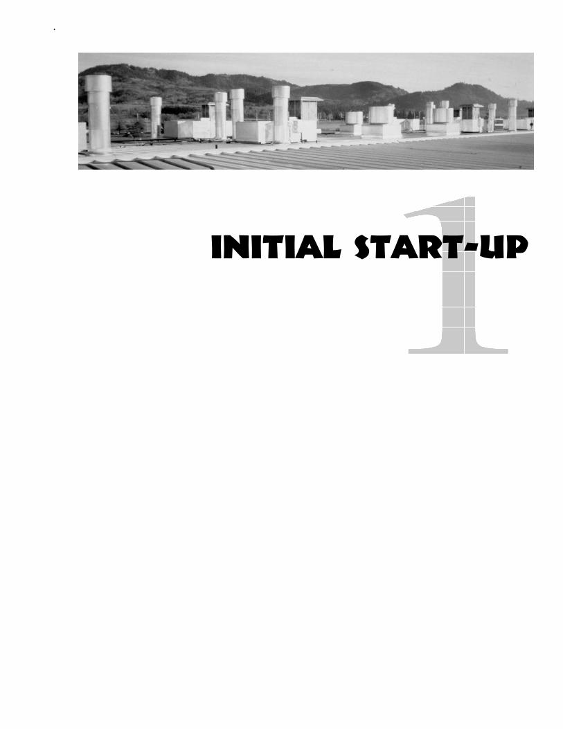
INITIAL START-UP
Initial Start-up
1-2
1.0 Safety Precautions 1.0.1 Fire Safety
The interior of the spray booth is rated as a Class 1, Division 1 hazardous area. Except for vehicles or parts to be painted, no sparks, spark generating equipment, or open flame inside the spray booth at any time. Three feet around any opening into the booth is a rated Class 1, Division 2 hazardous area. Caution should be taken not to place or have any flammable or flame causing equipment within three feet of any booth openings.
1.0.2 Tampering with Safety Equipment
All AFC Finishing Systems spray booths are designed and built to the standard of the National Fire Protection Agency (NFPA 33, NFPA 86, NFPA 91, NFPA 101, NFPA 70), the Occupational Safety and Health Act (OSHA), BOCA (National Fire Prevention, National Building Code, & National Mechanical Code), the Uniform Fire Code (UFC), Uniform Building Code (UBC), and the Uniform Mechanical Code (UMC). All safety equipment, limit switches, air solenoid valve, etc., must not be tampered with. If the particular piece of equipment does not operate correctly, please have a qualified technicianfix the problem immediately.
1.0.3 Installation
Improper installation, adjustment, alteration, service or maintenance can cause injury or property damage. Refer to this manual and the Power Flame burner manual. For additional assistance or additional information, consult a qualified installer, service agency, or call AFC Finishing Systems at our toll-free number, (800) 331-7744.
WARNING Fire or explosion hazard.
Can cause property damage, severe injury, or death. Verify safety requirements whenever
installing a spray booth control system.
CAUTION Electrical shock hazard or equipment/control
damage. Can cause electrical shock or equipment damage. Disconnect power supply
before beginning installation.
1.1 Initial start-up procedure 1.1.1 Initial start-up
1. Turn off all power to control panel. 2. Tighten all electrical connections (field and factory) in
AFC Finishing Systems control panel. 3. Tighten all electrical connections in Power Flame
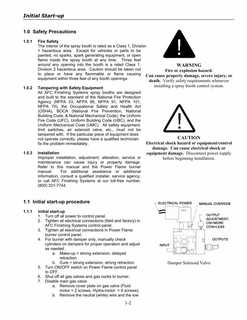
burner control panel. 4. For burner with damper only, manually check
cylinders on dampers for proper operation and adjust as needed.
a. Make-up = strong extension, delayed retraction.
b. Cure = strong extension, strong retraction. 5. Turn ON/OFF switch on Power Flame control panel
to OFF. 6. Shut off all gas valves and gas cocks to burner. 7. Disable main gas valve.
a. Remove cover plate on gas valve (Fluid motor = 2 screws, Hydra-motor = 6 screws).
b. Remove the neutral (white) wire and the low
Damper Solenoid Valve

Initial Start-up
1-3
fire wire ( L2 or N or com and 3 or low fire). c. Tape ends.
1.1.2 Initial paint cycle test
1. Turn on power to control panel. 2. Close all doors on booth. 3. Touch the PAINT button on the AFC Finishing
Systems Control panel to put the system in Paint (spray mode).
4. Verify that make-up damper is open. 5. Verify that cure damper is closed.
Paint Button
6. Verify that all motor contactors are energized. 7. Check and make sure that air valve is on. (From the
main screen, press “STATUS”, then look at “Spray Air”: 1 = on).
8. Check all motors for proper rotation, belt tension, and belt alignment.
9. Record current drawn (amperage) of all motors. 10. Open booth doors one at a time to check limit switch
circuit. Air valve and exhaust fan(s) should de-energize when any one door is open. There is a factory default delay of 10-seconds on the doors.
11. Touch the “PAINT” button again to turn the system OFF. Note that if the system is off, touching the button will turn it on; if the system is on, touching the button will turn it off.
12. Verify that all motors stop (after a three-second delay).
13. Verify that make-up damper is closed. 1.1.3 Initial cure cycle test
1. Touch the “CURE” button (on Main Screen). 2. Touch Setting to go to setting screen.
Cure Button
Initial Start-up
1-4
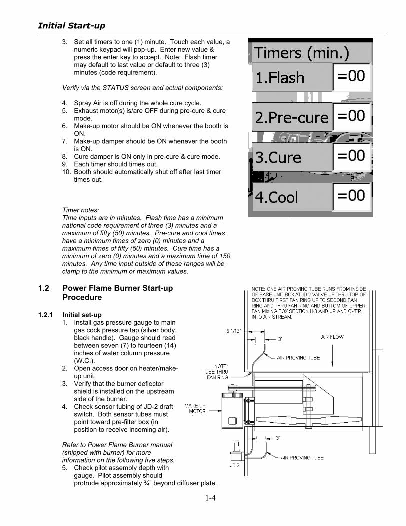
3. Set all timers to one (1) minute. Touch each value, a numeric keypad will pop-up. Enter new value & press the enter key to accept. Note: Flash timer may default to last value or default to three (3) minutes (code requirement).
Verify via the STATUS screen and actual components: 4. Spray Air is off during the whole cure cycle. 5. Exhaust motor(s) is/are OFF during pre-cure & cure
mode. 6. Make-up motor should be ON whenever the booth is
ON. 7. Make-up damper should be ON whenever the booth
is ON. 8. Cure damper is ON only in pre-cure & cure mode. 9. Each timer should times out. 10. Booth should automatically shut off after last timer
times out. Timer notes: Time inputs are in minutes. Flash time has a minimum national code requirement of three (3) minutes and a maximum of fifty (50) minutes. Pre-cure and cool times have a minimum times of zero (0) minutes and a maximum times of fifty (50) minutes. Cure time has a minimum of zero (0) minutes and a maximum time of 150 minutes. Any time input outside of these ranges will be clamp to the minimum or maximum values.
1.2 Power Flame Burner Start-up
Procedure 1.2.1 Initial set-up
1. Install gas pressure gauge to main gas cock pressure tap (silver body, black handle). Gauge should read between seven (7) to fourteen (14) inches of water column pressure (W.C.).
2. Open access door on heater/make-up unit.
3. Verify that the burner deflector shield is installed on the upstream side of the burner.
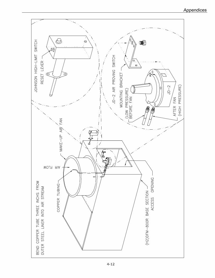
4. Check sensor tubing of JD-2 draft switch. Both sensor tubes must point toward pre-filter box (in position to receive incoming air).
Refer to Power Flame Burner manual (shipped with burner) for more information on the following five steps. 5. Check pilot assembly depth with
gauge. Pilot assembly should protrude approximately ¾” beyond diffuser plate.

Initial Start-up
1-5
6. Remove pilot assembly. 7. Check electrode gap and depth. 8. Check pilot burner deflector position. 9. Replace pilot assembly 10. Close access door.
1.2.2 Pilot ignition
1. Verify that all gas cocks and shut-off valves are in the closed positions.
2. Hook up manometer to pilot pressure tap (pilot tee). 3. Hook up Volt/Ohm meter on test jack (+,-) on
Honeywell controller, RM7895. 4. Verify that the main gas valve (Honeywell Fluid Motor
or the ASCO Hydramotor) is disabled. 5. On AFC control panel, touch “PAINT” to turn on
system. 6. ON AFC control panel, touch “BURNER” to turn on
burner. Note that burner will only turn on if system is turned on. The burner switch may be on, but the burner will not come on until the system is on.
7. Turn on pilot gas cock valve (yellow handle in front of blue Power Flame control box).
8. Turn ON/OFF switch on Power Flame control panel to ON.
9. Zero manometer after combustion blower on burner is up to speed.
10. Read pilot pressure on manometer when pilot solenoid opens – approximately seven (7) seconds.
11. Adjust pilot pressure to approximately 2” W.C. by adjusting pilot regulator.
12. Observe “Flame” LED light on controller. LED light should be lit when flame signal reading is at or above 1.25VDC.
13. Observe pilot flame through sight glass. There should be a lazy blue flame.
14. Verify and record pilot flame signal (DC Voltage). Signal should be 4.0 to 5.0 Volt D.C.
15. Make any necessary adjustments to stablize pilot flame signal reading (i.e. pilot pressure and/or combustion air damper adjustment).
16. Manually open combustion air damper doors half way by lifting linkage arm. Pilot flame signal should not drop below 1.25VDC.
17. Cycle power and test for establishment of pilot flame by turning ON/OFF switch on Power Flame control panel to OFF then ON. Assure proper ignition of pilot flame.
18. Turn ON/OFF switch on Power Flame control panel to OFF.
19. With the system still on, touch the “Paint” button again to turn off the system.
20. Shut off pilot gas cock.
Note: Refer to Power Flame J30A burner manual for more information. The burner manual is shipped with the burner inside a manila envelope. Additional information may also be obtained from Power Flame by either writing, calling, or visiting Power Flame or Power Flame’s website: Power Flame Incorporated 2001 South 21st Street Parsons, Kansas 67357 Ph: 620-421-0480, Fax: 800-862-4256 Web site: www.powerflame.com Email: [email protected]
1.2.2 Low-fire test 1. If using only one manometer, remove manometer
from pilot pressure tap and replace plug. 2. Check for orifice by removing 1” plug on orifice tee.
(Natural gas has no orifice; LPG orifice must be installed otherwise).
ASCO Hydramotor wiring
Initial Start-up
1-6
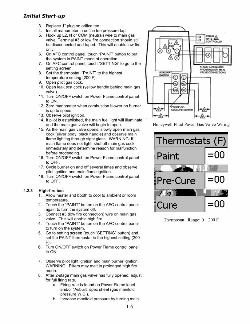
3. Replace 1” plug on orifice tee. 4. Install manometer in orifice tee pressure tap. 5. Hook up L2, N or COM (neutral) wire to main gas
valve. Terminal #3 or low fire connection should still be disconnected and taped. This will enable low fire only.
6. On AFC control panel, touch “PAINT” button to put the system in PAINT mode of operation.
7. On AFC control panel, touch “SETTING” to go to the setting screen.
8. Set the thermostat, “PAINT” to the highest temperature setting (200 F).
9. Open pilot gas cock. 10. Open leak test cock (yellow handle behind main gas
valve). 11. Turn ON/OFF switch on Power Flame control panel
to ON. 12. Zero manometer when combustion blower on burner
is up to speed. 13. Observe pilot ignition. 14. If pilot is established, the main fuel light will illuminate
and the main gas valve will begin to open. 15. As the main gas valve opens, slowly open main gas
cock (silver body, black handle) and observe main flame lighting through sight glass. WARNING: If main flame does not light, shut off main gas cock immediately and determine reason for malfunction before proceeding.
16. Turn ON/OFF switch on Power Flame control panel to OFF.
17. Cycle burner on and off several times and observe pilot ignition and main flame ignition.
18. Turn ON/OFF switch on Power Flame control panel to OFF.
1.2.3 High-fire test
1. Allow heater and booth to cool to ambient or room temperature.
2. Touch the “PAINT” button on the AFC control panel again to turn the system off.
3. Connect #3 (low fire connection) wire on main gas valve. This will enable high fire.
4. Touch the “PAINT” button on the AFC control panel to turn on the system.
5. Go to setting screen (touch “SETTING” button) and set the PAINT thermostat to the highest setting (200 F).
6. Turn ON/OFF switch on Power Flame control panel to ON.
7. Observe pilot light ignition and main burner ignition.
WARNING: Filters may melt in prolonged high fire mode.
8. After 2-stage main gas valve has fully opened, adjust for full firing rate.
a. Firing rate is found on Power Flame label and/or “Asbuilt” spec sheet (gas manifold pressure W.C.).
b. Increase manifold pressure by turning main
Honeywell Fluid Power Gas Valve Wiring
Thermostat. Range: 0 – 200 F
Initial Start-up
1-7
gas regulator screw clockwise. c. Decrease manifold pressure by turning main
gas regulator screw counter-clockwise. 9. After high fire manifold pressure is set, turn ON/OFF
switch on Power Flame control panel to OFF. 10. Again, allow heater and paint booth to cool to
ambient or room temperature. 11. On the main screen of the AFC control panel, touch
the “PAINT” button to turn off the system. 12. Remove all gauges and meters from burner. 13. Replace all plugs, caps, and covers on burner.
1.3 Full Operation Test 1.3.1 Paint cycle
1. Turn ON/OFF switch on Power Flame control panel to ON.
2. Touch the “PAINT” button on the AFC control panel to put the system in Painting (Spraying) mode of operation.
3. Adjust thermostat to normal painting temperature (Consult paint manufacturer – on paint can – for normal painting temperature).
4. Observe proper heating of booth.
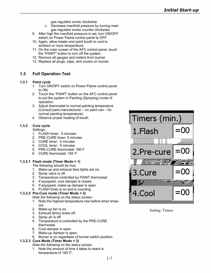
1.3.2 Cure cycle Settings: 1. FLASH timer: 5 minutes 2. PRE-CURE timer: 5 minutes 3. CURE timer: 5 minutes 4. COOL timer: 5 minutes 5. PRE-CURE thermostat: 180 F 6. CURE thermostat: 155EF
1.3.2.1 Flash mode (Timer Mode = 1) The following should be true. 1. Make-up and exhaust fans lights are on. 2. Spray valve is off. 3. Temperature controlled by PAINT thermostat 4. If equipped, cure damper is closed. 5. If equipped, make-up damper is open. 6. FLASH timer is on and is counting.
1.3.2.2 Pre-Cure mode (Timer Mode = 2) Note the following on the status screen. 1. Note the highest temperature rise before timer times
out. 2. Make-up fan is on. 3. Exhaust fan(s) is/are off. 4. Spray air is off. 5. Temperature is controlled by the PRE-CURE
thermostat. 6. Cure damper is open. 7. Make-up damper is open. 8. Burner is on regardless of burner switch position.
1.3.2.3 Cure Mode (Timer Mode = 3) Note the following on the status screen. 1. Note the amount of time it takes to reach a
temperature of 140EF.
Setting: Timers
Initial Start-up
1-8
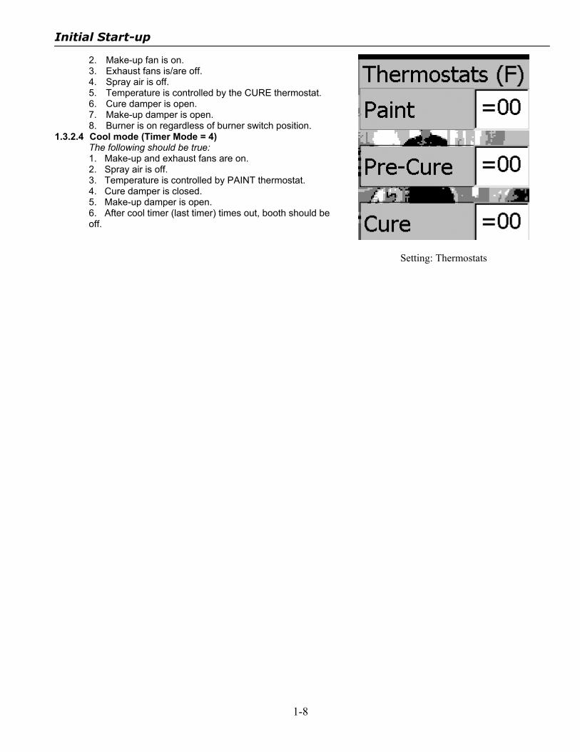
2. Make-up fan is on. 3. Exhaust fans is/are off. 4. Spray air is off. 5. Temperature is controlled by the CURE thermostat. 6. Cure damper is open. 7. Make-up damper is open. 8. Burner is on regardless of burner switch position.
1.3.2.4 Cool mode (Timer Mode = 4) The following should be true: 1. Make-up and exhaust fans are on. 2. Spray air is off. 3. Temperature is controlled by PAINT thermostat. 4. Cure damper is closed. 5. Make-up damper is open. 6. After cool timer (last timer) times out, booth should be off.
Setting: Thermostats

.
Operation
Operation
2-2
2.0 Operator Pre-start 2.0.1 Safety Equipment
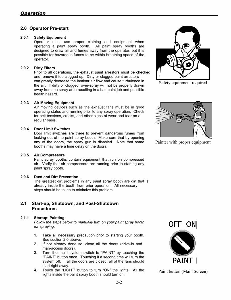
Operator must use proper clothing and equipment when operating a paint spray booth. All paint spray booths are designed to draw air and fumes away from the operator, but it is possible for hazardous fumes to be within breathing space of the operator.
2.0.2 Dirty Filters Prior to all operations, the exhaust paint arrestors must be checked and remove if too clogged up. Dirty or clogged paint arrestors can greatly decrease the laminar air flow and cause turbulence in the air. If dirty or clogged, over-spray will not be properly drawn away from the spray area resulting in a bad paint job and possible health hazard.
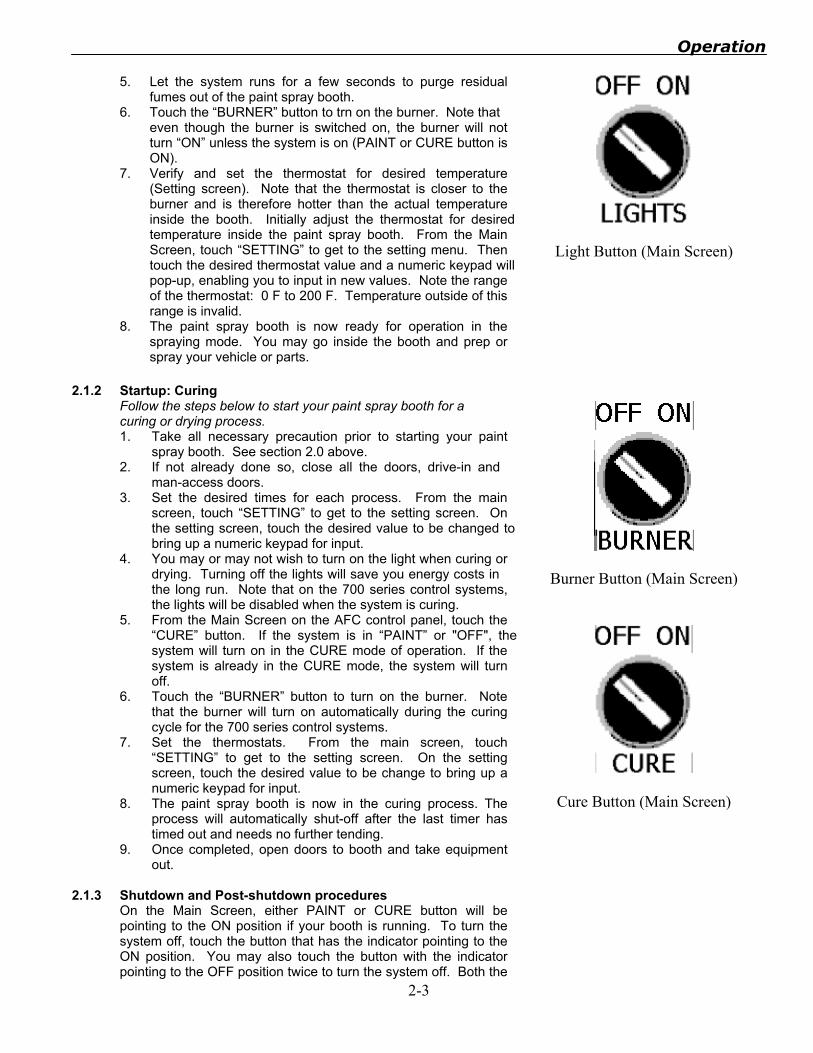
2.0.3 Air Moving Equipment Air moving devices such as the exhaust fans must be in good operating status and running prior to any spray operation. Check for belt tensions, cracks, and other signs of wear and tear on a regular basis.
2.0.4 Door Limit Switches Door limit switches are there to prevent dangerous fumes from leaking out of the paint spray booth. Make sure that by opening any of the doors, the spray gun is disabled. Note that some booths may have a time delay on the doors.
2.0.5 Air Compressors Paint spray booths contain equipment that run on compressed air. Verify that air compressors are running prior to starting any paint spray booth.
2.0.6 Dust and Dirt Prevention The greatest dirt problems in any paint spray booth are dirt that isalready inside the booth from prior operation. All necessary steps should be taken to minimize this problem.
Safety equipment required
Painter with proper equipment
2.1 Start-up, Shutdown, and Post-Shutdown Procedures
2.1.1 Startup: Painting Follow the steps below to manually turn on your paint spray booth for spraying. 1. Take all necessary precaution prior to starting your booth.
See section 2.0 above. 2. If not already done so, close all the doors (drive-in and
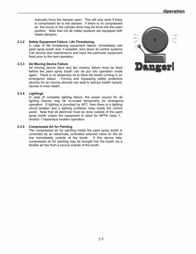
man-access doors). 3. Turn the main system switch to “PAINT” by touching the
“PAINT” button once. Touching it a second time will turn the system off. If all the doors are closed, all of the fans should start right away.
4. Touch the “LIGHT” button to turn “ON” the lights. All the lights inside the paint spray booth should turn on.
Paint button (Main Screen)
Operation
2-3
5. Let the system runs for a few seconds to purge residual fumes out of the paint spray booth.
6. Touch the “BURNER” button to trn on the burner. Note that even though the burner is switched on, the burner will not turn “ON” unless the system is on (PAINT or CURE button is ON).
7. Verify and set the thermostat for desired temperature (Setting screen). Note that the thermostat is closer to the burner and is therefore hotter than the actual temperature inside the booth. Initially adjust the thermostat for desired temperature inside the paint spray booth. From the Main Screen, touch “SETTING” to get to the setting menu. Then touch the desired thermostat value and a numeric keypad will pop-up, enabling you to input in new values. Note the range of the thermostat: 0 F to 200 F. Temperature outside of this range is invalid.
8. The paint spray booth is now ready for operation in the spraying mode. You may go inside the booth and prep or spray your vehicle or parts.
Light Button (Main Screen)
2.1.2 Startup: Curing Follow the steps below to start your paint spray booth for a curing or drying process. 1. Take all necessary precaution prior to starting your paint
spray booth. See section 2.0 above. 2. If not already done so, close all the doors, drive-in and
man-access doors. 3. Set the desired times for each process. From the main
screen, touch “SETTING” to get to the setting screen. On the setting screen, touch the desired value to be changed to bring up a numeric keypad for input.
4. You may or may not wish to turn on the light when curing or drying. Turning off the lights will save you energy costs in the long run. Note that on the 700 series control systems, the lights will be disabled when the system is curing.
5. From the Main Screen on the AFC control panel, touch the “CURE” button. If the system is in “PAINT” or "OFF", the system will turn on in the CURE mode of operation. If the system is already in the CURE mode, the system will turn off.
6. Touch the “BURNER” button to turn on the burner. Note that the burner will turn on automatically during the curing cycle for the 700 series control systems.
7. Set the thermostats. From the main screen, touch “SETTING” to get to the setting screen. On the setting screen, touch the desired value to be change to bring up a numeric keypad for input.
8. The paint spray booth is now in the curing process. The process will automatically shut-off after the last timer has timed out and needs no further tending.
9. Once completed, open doors to booth and take equipment out.
Burner Button (Main Screen)
Cure Button (Main Screen)
2.1.3 Shutdown and Post-shutdown procedures On the Main Screen, either PAINT or CURE button will be pointing to the ON position if your booth is running. To turn the system off, touch the button that has the indicator pointing to the ON position. You may also touch the button with the indicator pointing to the OFF position twice to turn the system off. Both the

Operation
2-4
PAINT and CURE button have to be in the OFF position for the booth to be turned off. There is a three second off delay. The whole booth will be off except for the lights. The lights can be turned off anytime with the light switch. Paint spray booths require the air compressor for operation. Be sure to shut down the air compressor if it is no longer in use by any other operation. Close all doors to the paint spray booth to prevent dirt and dust particles from entering the booth when it is off.
2.2 Normal Operations
The following steps for paint spray booth operation are typical for all paint spray booth operations. 1. Properly prepare all vehicles or parts outside of the paint
spray booth. 2. Bring vehicle or parts to be painted inside the paint spray
booth. 3. Prepare vehicle or parts for painting. 4. Close all drive-in doors. 5. Turn on booth via control panel outside of the paint spray
booth (PAINT button = ON). 6. Go inside the paint spray booth and close all man-access
doors. 7. Paint vehicle or parts. 8. Once painting is finished, go outside of the paint spray booth
to the main control panel. 9. Verify that the timers are set correctly. 10. Turn main switch to CURE by touching the CURE button
(CURE button = ON). 11. Verify the temperature and thermostat setting (Setting
Screen). 12. The curing/baking process is done when all timers have
timed out. 13. The booth will automatically shut off. 14. Remove vehicle or parts from the paint spray booth. 15. Repeat process from step #1 above.
Spraying Operation
2.3 Emergency Operations
2.3.1 Safety Equipment Failure, Non-life Threatening Paint spray booth safety equipment, like all other mechanical equipment, will eventually fail due to wear and tear. The few safety devices on paint spray booths that may be safely bypassed for short, emergency operations are: 1. Door limit switches. Door limit switches may be temporarily
bypassed by tying the two wires on terminal 3 and terminal 4 inside the switch together. Be sure to disable all power sources to the control panel prior to bypassing to prevent electrical shocks.
2. Intake dampers. Intake dampers may be temporarily forced open for short emergency operation. The neck of the damper solenoid (located between the electrical and mechanical section) has a slotted screw with a zero (0) and a one (1) for manual open and closed. Using a slotted screw driver, turn the screw so that the slot points toward the one (1) to
Door Limit Switch
Operation
2-5
manually force the damper open. This will only work if there is compressed air to the damper. If there is no compressed air, the louver or the cylinder arms may be force into the open position. Note that not all intake systems are equipped with intake dampers.
2.3.2 Safety Equipment Failure, Life Threatening
In case of life threatening equipment failure, immediately exit paint spray booth and, if possible, shut down all control systems. Call service and maintenance and have the particular equipment fixed prior to the next operation.
2.3.3 Air Moving Device Failure Air moving device (fans and fan motors) failure must be fixed before the paint spray booth can be put into operation mode again. There is no temporary fix to have the booth running in an emergency status. Forcing and bypassing safety protective devices for air moving devices can lead to serious health hazard, injuries or even death.
2.3.4 Lightings In case of complete lighting failure, the power source for all lighting fixtures may be re-routed temporarily for emergency operation. If lighting is provided by AFC, then there is a lighting circuit breaker and a lighting contactor relay inside the control panel. Note that all electrical must be done outside of the paint spray booth unless the equipment is rated for NFPA class 1, division 1 hazardous location operation.
2.3.5 Compressed Air for Painting The compressed air for painting inside the paint spray booth is controlled by an electrically controlled solenoid valve on the air line immediately outside of the booth. If this device fails, compressed air for painting may be brought into the booth via a flexible air line from a source outside of the booth.
.
Maintenance
Maintenance
3-2
3.0 Operator Service Requirement The operator is required to make the following services and maintenance. 3.0.1 General Service
• Booth operator should practice good basic house keeping.
• There should be no prepping in the booth. • Door should be kept shut at all times to minimize the
amount of dirt carried into the booth • The interior should be vacuumed regularly, and the wall
wiped down to prevent the accumulation of combustible residues.
• Check the door, tie-bar, and light frame gaskets for damage and replace as needed.
• Check and replace light tubes as needed. • Check all joints on interior of booth and re-caulk any air
leaks. • Keep painting air system clean and dry.
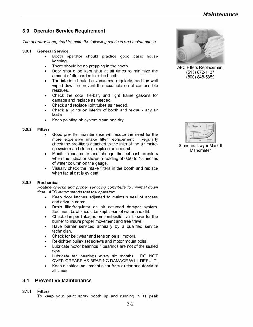
3.0.2 Filters • Good pre-filter maintenance will reduce the need for the
more expensive intake filter replacement. Regularly check the pre-filters attached to the inlet of the air make-up system and clean or replace as needed.
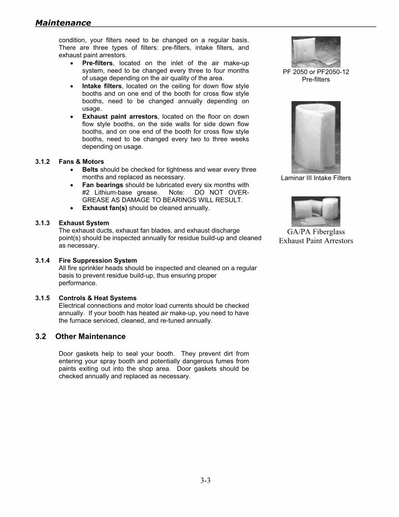
• Monitor manometer and change the exhaust arrestors when the indicator shows a reading of 0.50 to 1.0 inches of water column on the gauge.
• Visually check the intake filters in the booth and replace when facial dirt is evident.
3.0.3 Mechanical
Routine checks and proper servicing contribute to minimal down time. AFC recommends that the operator:
• Keep door latches adjusted to maintain seal of access and drive-in doors.
• Drain filter/regulator on air actuated damper system. Sediment bowl should be kept clean of water and dirt.
• Check damper linkages on combustion air blower for the burner to insure proper movement and free travel.
• Have burner serviced annually by a qualified service technician.
• Check for belt wear and tension on all motors. • Re-tighten pulley set screws and motor mount bolts. • Lubricate motor bearings if bearings are not of the sealed
type. • Lubricate fan bearings every six months. DO NOT
OVER-GREASE AS BEARING DAMAGE WILL RESULT. • Keep electrical equipment clear from clutter and debris at
all times.
AFC Filters Replacement
(515) 872-1137 (800) 848-5859
Standard Dwyer Mark II
Manometer
3.1 Preventive Maintenance 3.1.1 Filters
To keep your paint spray booth up and running in its peak
Maintenance
3-3
condition, your filters need to be changed on a regular basis. There are three types of filters: pre-filters, intake filters, and exhaust paint arrestors.
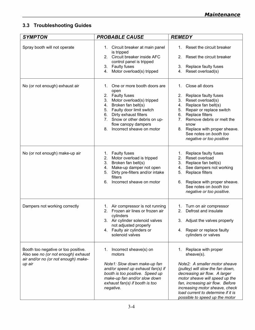
• Pre-filters, located on the inlet of the air make-up system, need to be changed every three to four months of usage depending on the air quality of the area.
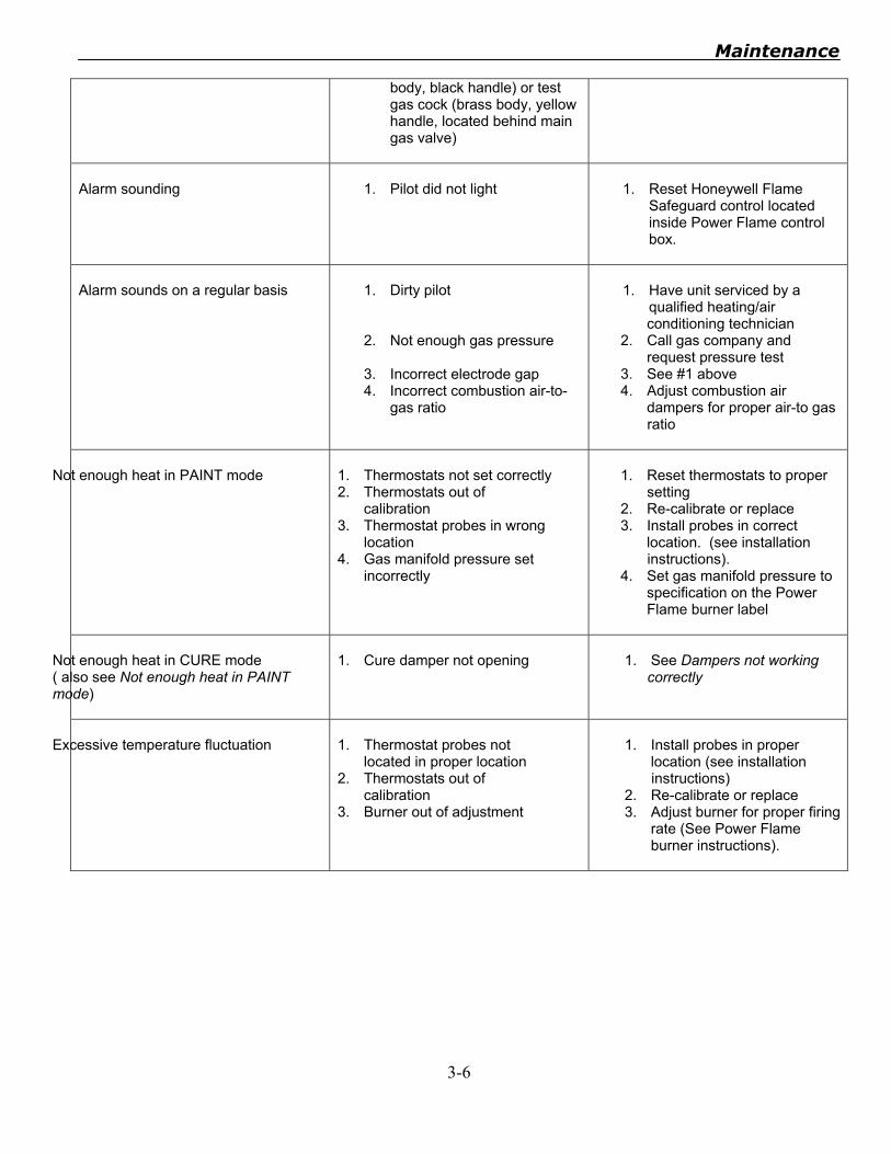
• Intake filters, located on the ceiling for down flow style booths and on one end of the booth for cross flow style booths, need to be changed annually depending on usage.
• Exhaust paint arrestors, located on the floor on down flow style booths, on the side walls for side down flow booths, and on one end of the booth for cross flow style booths, need to be changed every two to three weeks depending on usage.
3.1.2 Fans & Motors
• Belts should be checked for tightness and wear every three months and replaced as necessary.
• Fan bearings should be lubricated every six months with #2 Lithium-base grease. Note: DO NOT OVER-GREASE AS DAMAGE TO BEARINGS WILL RESULT.
• Exhaust fan(s) should be cleaned annually.
3.1.3 Exhaust System The exhaust ducts, exhaust fan blades, and exhaust discharge point(s) should be inspected annually for residue build-up and cleaned as necessary.
3.1.4 Fire Suppression System All fire sprinkler heads should be inspected and cleaned on a regular basis to prevent residue build-up, thus ensuring proper performance.
3.1.5 Controls & Heat Systems Electrical connections and motor load currents should be checked annually. If your booth has heated air make-up, you need to have the furnace serviced, cleaned, and re-tuned annually.
PF 2050 or PF2050-12
Pre-filters
Laminar III Intake Filters
GA/PA Fiberglass
Exhaust Paint Arrestors
3.2 Other Maintenance
Door gaskets help to seal your booth. They prevent dirt from entering your spray booth and potentially dangerous fumes from paints exiting out into the shop area. Door gaskets should be checked annually and replaced as necessary.
Maintenance
3-4
3.3 Troubleshooting Guides SYMPTON PROBABLE CAUSE REMEDY Spray booth will not operate
1. Circuit breaker at main panel
is tripped 2. Circuit breaker inside AFC
control panel is tripped 3. Faulty fuses 4. Motor overload(s) tripped
1. Reset the circuit breaker 2. Reset the circuit breaker
3. Replace faulty fuses 4. Reset overload(s)
No (or not enough) exhaust air
1. One or more booth doors are
open 2. Faulty fuses 3. Motor overload(s) tripped 4. Broken fan belt(s) 5. Faulty door limit switch 6. Dirty exhaust filters 7. Snow or other debris on up-
flow canopy dampers 8. Incorrect sheave on motor
1. Close all doors 2. Replace faulty fuses 3. Reset overload(s) 4. Replace fan belt(s) 5. Repair or replace switch 6. Replace filters 7. Remove debris or melt the
snow 8. Replace with proper sheave.
See notes on booth too negative or too positive
No (or not enough) make-up air
1. Faulty fuses 2. Motor overload is tripped 3. Broken fan belt(s) 4. Make-up damper not open 5. Dirty pre-filters and/or intake
filters 6. Incorrect sheave on motor
1. Replace faulty fuses 2. Reset overload 3. Replace fan belt(s) 4. See dampers not working 5. Replace filters 6. Replace with proper sheave.
See notes on booth too negative or too positive.
Dampers not working correctly
1. Air compressor is not running 2. Frozen air lines or frozen air
cylinders 3. Air cylinder solenoid valves
not adjusted properly 4. Faulty air cylinders or
solenoid valves
1. Turn on air compressor 2. Defrost and insulate 3. Adjust the valves properly
4. Repair or replace faulty
cylinders or valves
Booth too negative or too positive. Also see no (or not enough) exhaust air and/or no (or not enough) make-up air
1. Incorrect sheave(s) on
motors Note1: Slow down make-up fan and/or speed up exhaust fan(s) if booth is too positive. Speed up make-up fan and/or slow down exhaust fan(s) if booth is too negative.
1. Replace with proper
sheave(s). Note2: A smaller motor sheave (pulley) will slow the fan down, decreasing air flow. A larger motor sheave will speed up the fan, increasing air flow. Before increasing motor sheave, check load current to determine if it is possible to speed up the motor

Maintenance
3-5
without causing an over-current. The motor load current should be at or below the full load amps (FLA) stamped on the motor rating plate.
No air pressure at compressed air line in booth
1. One or more booth doors are
opened 2. Faulty door limit switch 3. Debris in solenoid valve 4. Solenoid valve not installed
correctly (air flow direction incorrect)
1. Close all doors 2. Repair or replace faulty
switch 3. Remove debris 4. Install valve correctly (if
compressed air has already been applied to solenoid, diaphragm is probably damaged and needs to be repaired. Repair kits are available from AFC.
The following section is applicable only for heated air make-up systems equipped with the Power Flame J Burner. For all other troubleshooting help, contact AFC technical support at 800-331-7744. SYMPTOM PROBABLE CAUSE REMEDY No heat – “Power ON” light on Power Flame control box is “OFF”
1. Burner switch on AFC control
panel is in the “OFF” position 2. ON/OFF control switch on
Power Flame control box is in the “OFF” position
3. Johnson Control high limit switch is tripped (located by the make-up fan motor)
1. Turn switch on. 2. Turn switch on.
3. Push reset button on top of
limit switch.
No heat – “Power ON” light on Power Flame control box is “ON”, “Main Fuel” light is “OFF”.
1. No (or not enough) make-up
air (JD-2 Air Flow Switch located by make-up fan motor is not closing)
2. JD-2 Air Flow Switch wired incorrectly
3. JD-2 Air Sensing Tubes not adjusted correctly
1. See No (or not enough
make-up air). 2. Should be wired to “COM”
and “N.O.” 3. Adjust tubes to correct
positions (approximately 3” from duct walls and pointing to receive incoming air from the pre-filters.
No heat – “Power ON” light on Power Flame control box is “ON”, “Main Fuel” light is “ON”
1. Thermostats not set properly 2. Thermostat(s) out of
calibration 3. Main gas cock closed (silver
1. Set thermostats to proper
setting 2. Re-calibrate or replace
thermostat(s) 3. Open gas cock(s)
Maintenance
3-6
body, black handle) or test gas cock (brass body, yellow handle, located behind main gas valve)
Alarm sounding
1. Pilot did not light
1. Reset Honeywell Flame
Safeguard control located inside Power Flame control box.
Alarm sounds on a regular basis
1. Dirty pilot
2. Not enough gas pressure 3. Incorrect electrode gap 4. Incorrect combustion air-to-
gas ratio
1. Have unit serviced by a
qualified heating/air conditioning technician
2. Call gas company and request pressure test
3. See #1 above 4. Adjust combustion air
dampers for proper air-to gas ratio
Not enough heat in PAINT mode
1. Thermostats not set correctly 2. Thermostats out of
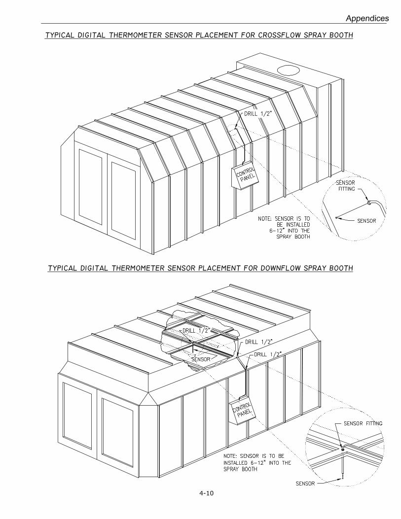
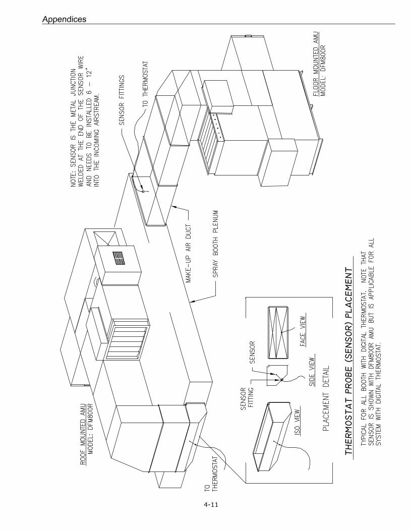
calibration 3. Thermostat probes in wrong
location 4. Gas manifold pressure set
incorrectly
1. Reset thermostats to proper
setting 2. Re-calibrate or replace 3. Install probes in correct
location. (see installation instructions).
4. Set gas manifold pressure to specification on the Power Flame burner label
Not enough heat in CURE mode ( also see Not enough heat in PAINT mode)
1. Cure damper not opening
1. See Dampers not working
correctly
Excessive temperature fluctuation
1. Thermostat probes not
located in proper location 2. Thermostats out of
calibration 3. Burner out of adjustment
1. Install probes in proper
location (see installation instructions)
2. Re-calibrate or replace 3. Adjust burner for proper firing
rate (See Power Flame burner instructions).
.
Appendices
Appendices
4-2
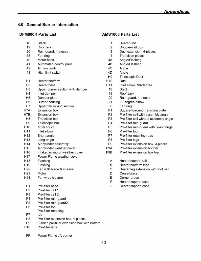
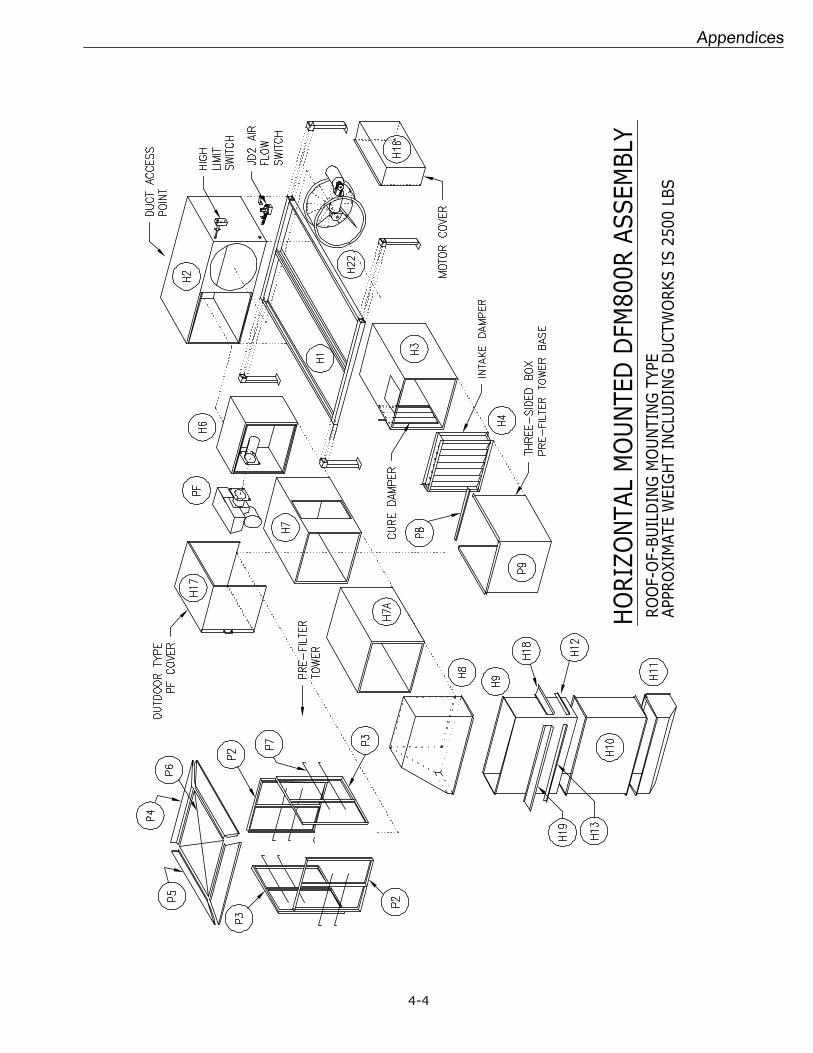
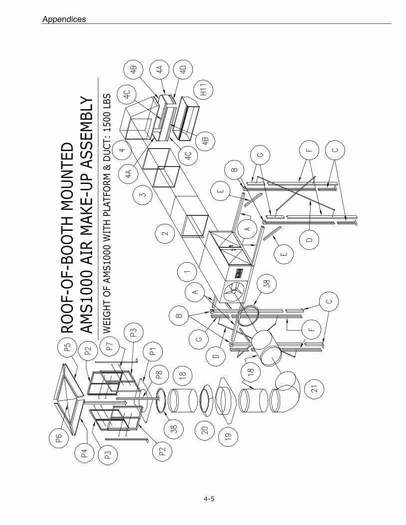
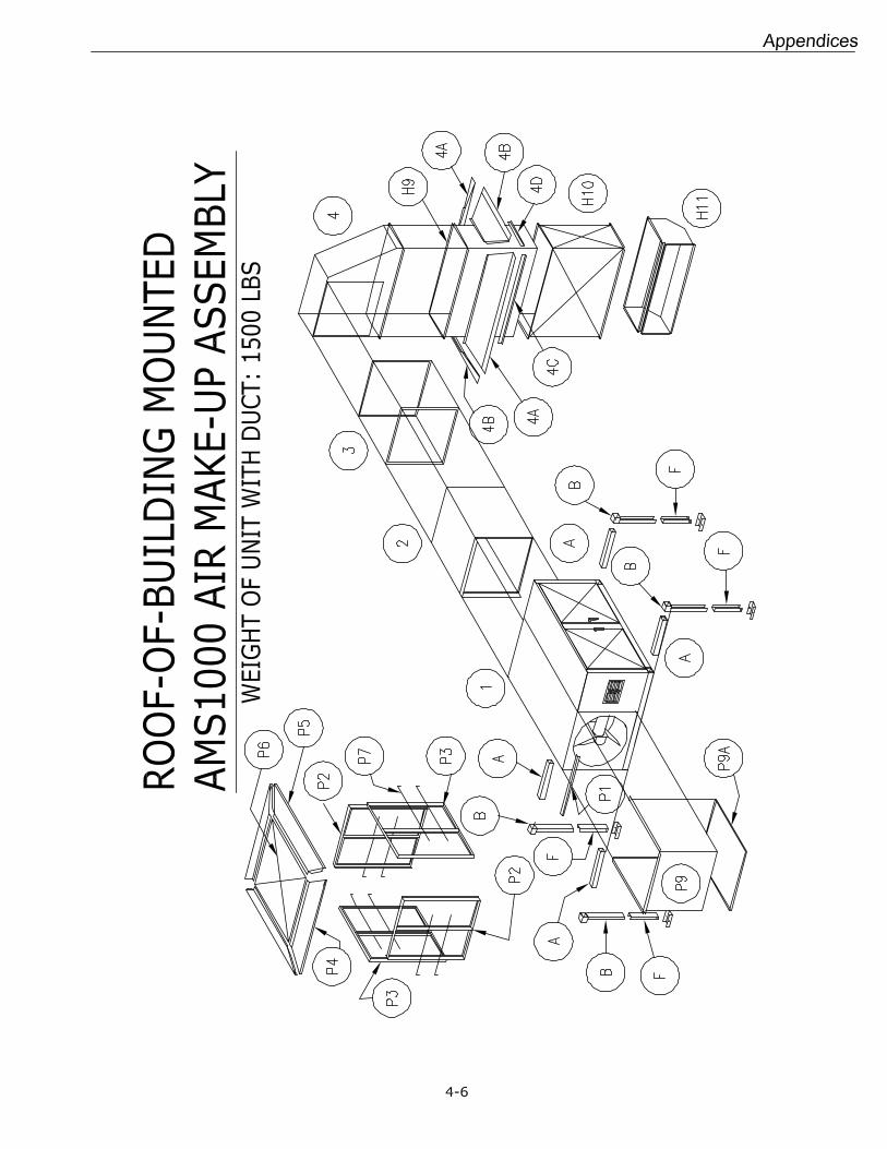
4.0 General Burner Information DFM800R Parts List AMS1000 Parts List
18 Stack 1 Heater unit 19 Roof jack 2 Double-wall box 20 Rain-guard, 4-pieces 3 Duct extension, 4-pieces 38 Fan ring 4 Transition pieces 40 Motor belts 4A Angle/Flashing 41 Automated control panel 4B Angle/Flashing 42 Air flow switch 4C Angle 43 High limit switch 4D Angle
H9 Telescopic Duct H1 Heater platform H10 Duct H2 Heater base H11 Inlet elbow, 90-degree H3 Upper burner section with damper 18 Stack H4 Inlet damper 19 Roof Jack H5 Damper plate 20 Rain-guard, 4-pieces H6 Burner housing 21 90-degree elbow H7 Upper fan mixing section 38 Fan ring
H7A Extension box P1 Square-to-round transition plate H7B Extension box P2 Pre-filter cell with assembly angle
H8 Transition box P3 Pre-filter cell without assembly angle H9 Telescopic box P4 Pre-filter rain-guard
H10 18x60 duct P5 Pre-filter rain-guard with tie-in flange H11 Inlet elbow P6 Pre-filter top H12 Short angle P7 Pre-filter retaining rods H13 Long angle P8 Pre-filter legs H14 Air cylinder assembly P9 Pre-filter extension box, 3-pieces H15 Air cylinder weather cover P9A Pre-filter extension bottom H16 Intake fan motor weather cover P9B Pre-filter extension box top H17 Power Flame weather cover H18 Flashing A Heater support rails H19 Flashing B Heater platform legs H22 Fan with blade & sheave C Heater leg extension with foot pad H23 Motor D Cross-brace H24 Fan wrap closure E Corner brace
F Heater support caps P1 Pre-filter base G Heater support caps P2 Pre-filter cell 1 P3 Pre-filter cell 2 P4 Pre-filter rain-guard1 P5 Pre-filter rain-guard2 P6 Pre-filter top
P7 Pre-filter retaining rod
P8 Pre-filter extension box, 4-pieces P9 3-sided pre-filter extension box with bottom
P10 Pre-filter legs
PF Power Flame JA burner

Appendices
4-13
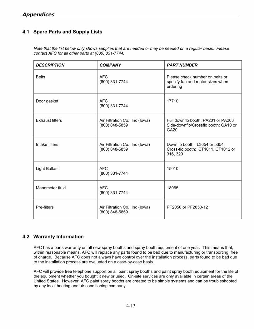
4.1 Spare Parts and Supply Lists
Note that the list below only shows supplies that are needed or may be needed on a regular basis. Please contact AFC for all other parts at (800) 331-7744.
DESCRIPTION COMPANY PART NUMBER Belts
AFC (800) 331-7744
Please check number on belts or specify fan and motor sizes when ordering
Door gasket
AFC (800) 331-7744
17710
Exhaust filters
Air Filtration Co., Inc (Iowa) (800) 848-5859
Full downflo booth: PA201 or PA203 Side-downflo/Crossflo booth: GA10 or GA20
Intake filters
Air Filtration Co., Inc (Iowa) (800) 848-5859
Downflo booth: L3654 or 5354 Cross-flo booth: CT1011, CT1012 or 316, 320
Light Ballast
AFC (800) 331-7744
15010
Manometer fluid
AFC (800) 331-7744
18065
Pre-filters
Air Filtration Co., Inc (Iowa) (800) 848-5859
PF2050 or PF2050-12
4.2 Warranty Information
AFC has a parts warranty on all new spray booths and spray booth equipment of one year. This means that, within reasonable means, AFC will replace any parts found to be bad due to manufacturing or transporting, free of charge. Because AFC does not always have control over the installation process, parts found to be bad due to the installation process are evaluated on a case-by-case basis. AFC will provide free telephone support on all paint spray booths and paint spray booth equipment for the life of the equipment whether you bought it new or used. On-site services are only available in certain areas of the United States. However, AFC paint spray booths are created to be simple systems and can be troubleshooted by any local heating and air conditioning company.

Notes
4-14

Notes
4-15