Embed Size (px)
DESCRIPTION
LOT procedures
Citation preview

Author: Peter Aird www.kingdomdrilling.co.uk Ref: F001
Extended leak off testing
Rev: 1.0 03/01/01
Author: Peter Aird www.kingdomdrilling.co.uk Ref: F001
Purpose To ensure minimal operational time and risk exposure to personnel, process, production and equipment. The following extended leak off test procedures will ensure that both well integrity and stability are maintained as effectively and as efficiently as practicable. If wellbore problems did occur, procedures in well specific guidelines and other relevant documents should be followed.
Responsibilities It will be the responsibility of the Operators drilling representative and senior contractor drilling personnel to ensure that others with duties relating operations contained within this document are aware of their roles and responsibilities.
Scope These procedures shall apply to all drilling personnel.
Further References Drilling contractor’s and Operator’s mutually agreed specific Extended leak off test Procedures.
Author: Peter Aird www.kingdomdrilling.co.uk Ref: F001
Table of contents
EXTENDED LEAK OFF TESTING.............................................................................................1
Purpose..........................................................................................................................................2
Responsibilities .............................................................................................................................2
Scope .............................................................................................................................................2
Further References ........................................................................................................................2
Table of contents ...........................................................................................................................3
Pre planning Preparations .............................................................................................................4
Pre job Procedures.........................................................................................................................5
EXTENDED LEAK OFF TEST? ..................................................................................................8
General ..........................................................................................................................................8
Draw guidelines on LOT chart (Fig. 1).........................................................................................9
During the test .............................................................................................................................11
Data interpretation.......................................................................................................................13
Retesting......................................................................................................................................14
Difference from standard L.O.T. procedures ..............................................................................15
Author: Peter Aird www.kingdomdrilling.co.uk Ref: F001
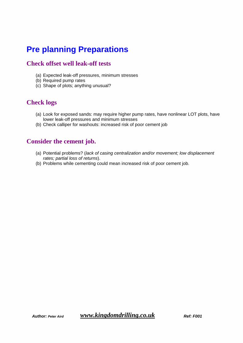
Pre planning Preparations
Check offset well leak-off tests
(a) Expected leak-off pressures, minimum stresses (b) Required pump rates (c) Shape of plots; anything unusual?
Check logs
(a) Look for exposed sands: may require higher pump rates, have nonlinear LOT plots, have lower leak-off pressures and minimum stresses
(b) Check calliper for washouts: increased risk of poor cement job
Consider the cement job.
(a) Potential problems? (lack of casing centralization and/or movement; low displacement rates; partial loss of returns).
(b) Problems while cementing could mean increased risk of poor cement job.
Author: Peter Aird www.kingdomdrilling.co.uk Ref: F001
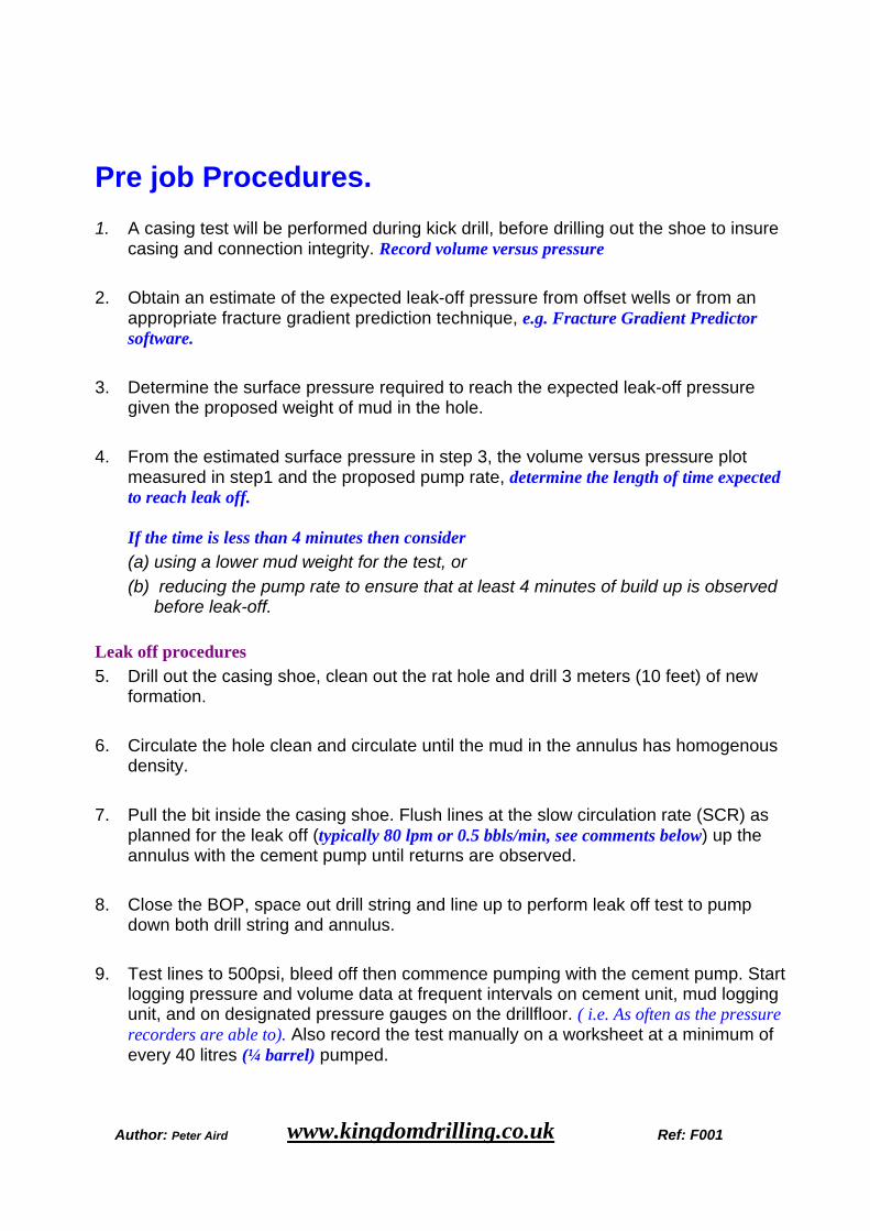
Pre job Procedures. 1. A casing test will be performed during kick drill, before drilling out the shoe to insure
casing and connection integrity. Record volume versus pressure
2. Obtain an estimate of the expected leak-off pressure from offset wells or from an appropriate fracture gradient prediction technique, e.g. Fracture Gradient Predictor software.
3. Determine the surface pressure required to reach the expected leak-off pressure given the proposed weight of mud in the hole.
4. From the estimated surface pressure in step 3, the volume versus pressure plot
measured in step1 and the proposed pump rate, determine the length of time expected to reach leak off.
If the time is less than 4 minutes then consider (a) using a lower mud weight for the test, or
(b) reducing the pump rate to ensure that at least 4 minutes of build up is observed before leak-off.
Leak off procedures 5. Drill out the casing shoe, clean out the rat hole and drill 3 meters (10 feet) of new
formation. 6. Circulate the hole clean and circulate until the mud in the annulus has homogenous
density. 7. Pull the bit inside the casing shoe. Flush lines at the slow circulation rate (SCR) as
planned for the leak off (typically 80 lpm or 0.5 bbls/min, see comments below) up the annulus with the cement pump until returns are observed.
8. Close the BOP, space out drill string and line up to perform leak off test to pump
down both drill string and annulus. 9. Test lines to 500psi, bleed off then commence pumping with the cement pump. Start
logging pressure and volume data at frequent intervals on cement unit, mud logging unit, and on designated pressure gauges on the drillfloor. ( i.e. As often as the pressure recorders are able to). Also record the test manually on a worksheet at a minimum of every 40 litres (¼ barrel) pumped.
Author: Peter Aird www.kingdomdrilling.co.uk Ref: F001
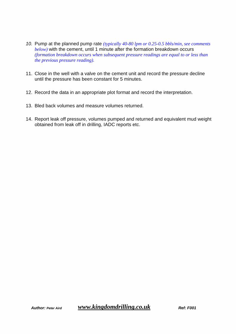
10. Pump at the planned pump rate (typically 40-80 lpm or 0.25-0.5 bbls/min, see comments below) with the cement, until 1 minute after the formation breakdown occurs (formation breakdown occurs when subsequent pressure readings are equal to or less than the previous pressure reading).
11. Close in the well with a valve on the cement unit and record the pressure decline until the pressure has been constant for 5 minutes.
12. Record the data in an appropriate plot format and record the interpretation. 13. Bled back volumes and measure volumes returned. 14. Report leak off pressure, volumes pumped and returned and equivalent mud weight
obtained from leak off in drilling, IADC reports etc.
Author: Peter Aird www.kingdomdrilling.co.uk Ref: F001
Comments to procedure:
Step 2 • Fracture Gradient Predictor can be obtained from operating and/or service
companies.
Step 4 • It is best to see a minimum of four pressure readings before leak-off occurs to
characterise the linear build of the pressure curve so that leak-off can be recognised.
Step 6 • Take care to clean the rat hole properly, so that the induced fracture will not be
propped open by cement or cuttings debris. • Consider pumping a hi-vis/hi-density pill to aid in clearing cuttings, which must be
circulated out of the hole before the start of the test. • If the mud weight is to be increased before drilling ahead, perform leak off before
increasing the mud weight to be able to optimise the display of the pressure/volume plot.
Step 10 • The planned pump rate should be a rate that builds pressure at a minimum of one
half the rate observed in the casing test. Typically, this would 80 lpm or 0.5 bbls/min. However, in shallow or higher permeability sediments, higher pumps rates may be required. If the initial pressure build rate is too low, repeat the test at a higher test rate. Pump rates of 120 to 160 lpm (0.75 to 1.0 bbls/min) may be required to get a satisfactory test. Caution: low pressure build rates can also be indicative of significantly increased borehole volume which may indicate the lack of cement behind the casing shoe.
• If there is a down hole pressure gauge that records data during the test (ex. PWD sub), it should be programmed to give reasonable sampling rate during the test (depends on memory size). Remember to synchronize all clocks (cement unit, mud-logger, PWD etc.) before the LOT.
Steps 13 and 14 • Bleed back should be done with a constant and low rate. • Avoid adjusting the valve during the bleed-back period, as this will disturb
interpretation of fracture closure during bleed-back.
Author: Peter Aird www.kingdomdrilling.co.uk Ref: F001
Extended leak off test?
General Modifications to standard leak off procedures ensure better quality of test results and come at the expense of some preparation on behalf of the testing engineer before the test. The modifications provide the following benefits:
1. Increase reliability and consistency of Leak-off pressure data.
2. Provide consistent and reliable estimates of minimum in-situ stress.
3. Provide calibration points for in situ stress profile and pore pressure estimates, including the quantification of fracture gradient changes in depleted reservoirs.
4. Detect cement channels and eliminate unnecessary cement squeezes.
5. Reduce risk of circulation loss.
6. Provide better data for kick control.
7. Improve estimates of mud-weight (MW) window for drilling operations.
8. Provide reliable data needed for drilling and production stability calculations.
9. Provide data needed for fracture stimulation design and completions.
10. Provide data needed for waste disposal down hole injection design.
The commonly expressed concern of weakening the formation because of the small fracture that is created during the Leak-off test, is however minimized by the following factors:
1. Fractures exist in the formation or are introduced by the drilling process anyway.
2. Fractures have the capacity to hold mud-weight.
3. In the rare case of an intact formation, the creation of a small fracture due to a LOT weakens the formation by a very small amount equal to the tensile strength of the formation which is negligible.
4. Mud solids plug the tip of the fracture and/or fill the crack restoring approximately the original capacity of the formation to hold mud-weight. Repeated LOTs and stress tests using clear fluids show that creating a small fracture is not a problem.
5. Shales are usually plastic and tend to heal after a fracture closes.
Author: Peter Aird www.kingdomdrilling.co.uk Ref: F001
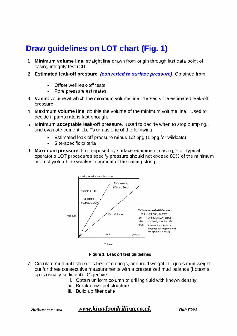
Draw guidelines on LOT chart (Fig. 1)
1. Minimum volume line: straight line drawn from origin through last data point of casing integrity test (CIT).
2. Estimated leak-off pressure (converted to surface pressure). Obtained from:
• Offset well leak-off tests • Pore pressure estimates
3. V.min: volume at which the minimum volume line intersects the estimated leak-off pressure.
4. Maximum volume line: double the volume of the minimum volume line. Used to decide if pump rate is fast enough.
5. Minimum acceptable leak-off pressure. Used to decide when to stop pumping, and evaluate cement job. Taken as one of the following:
• Estimated leak-off pressure minus 1/2 ppg (1 ppg for wildcats) • Site-specific criteria
6. Maximum pressure: limit imposed by surface equipment, casing, etc. Typical operator’s LOT procedures specify pressure should not exceed 80% of the minimum internal yield of the weakest segment of the casing string.
0
0.5
1
1.5
2
2.5
3
0 1 2 Volume
Pressure
Min. Volume
(Casing Test) Estimated LOP
Minimum Acceptable LOP
Maximum Allowable Pressure
Vmin
2*Vmin
Max. Volume Estimated Leak-Off Pressure
= 0.052*TVD*(Est-MW)
Est = estimated LOP (ppg)
MW = mudweight in the hole
TVD = true vertical depth to casing shoe (top of sand for open hole tests)
Figure 1: Leak off test guidelines
7. Circulate mud until shaker is free of cuttings, and mud weight in equals mud weight out for three consecutive measurements with a pressurized mud balance (bottoms up is usually sufficient). Objective:
i. Obtain uniform column of drilling fluid with known density ii. Break-down gel structure iii. Build up filter cake
Author: Peter Aird www.kingdomdrilling.co.uk Ref: F001
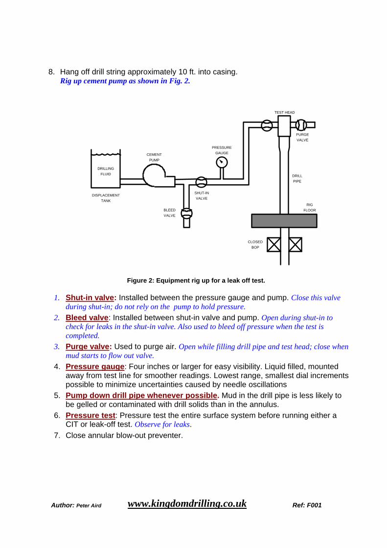
8. Hang off drill string approximately 10 ft. into casing. Rig up cement pump as shown in Fig. 2.
DISPLACEMENT
TANK
CEMENT
PUMP
PRESSURE
GAUGE
SHUT-IN
VALVE
BLEED
VALVE
PURGE
VALVE
DRILL
PIPE
RIG
FLOOR
CLOSED
BOP
DRILLING
FLUID
TEST HEAD
Figure 2: Equipment rig up for a leak off test.
1. Shut-in valve: Installed between the pressure gauge and pump. Close this valve during shut-in; do not rely on the pump to hold pressure.
2. Bleed valve: Installed between shut-in valve and pump. Open during shut-in to check for leaks in the shut-in valve. Also used to bleed off pressure when the test is completed.
3. Purge valve: Used to purge air. Open while filling drill pipe and test head; close when mud starts to flow out valve.
4. Pressure gauge: Four inches or larger for easy visibility. Liquid filled, mounted away from test line for smoother readings. Lowest range, smallest dial increments possible to minimize uncertainties caused by needle oscillations
5. Pump down drill pipe whenever possible. Mud in the drill pipe is less likely to be gelled or contaminated with drill solids than in the annulus.
6. Pressure test: Pressure test the entire surface system before running either a CIT or leak-off test. Observe for leaks.
7. Close annular blow-out preventer.
Author: Peter Aird www.kingdomdrilling.co.uk Ref: F001
During the test
Pumping
1. Maintain constant pump rate. 2. Try 1/4 bbl/min unless offset well data indicates otherwise.
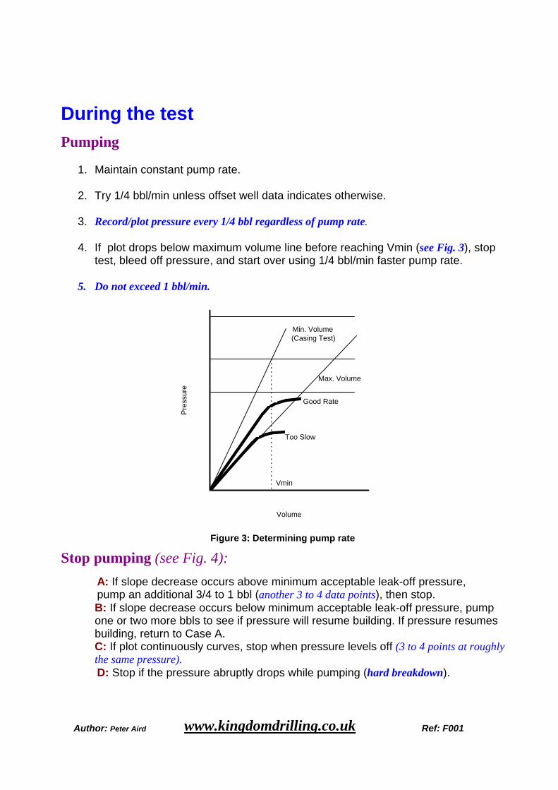
3. Record/plot pressure every 1/4 bbl regardless of pump rate.
4. If plot drops below maximum volume line before reaching Vmin (see Fig. 3), stop
test, bleed off pressure, and start over using 1/4 bbl/min faster pump rate.
5. Do not exceed 1 bbl/min.
0
0.5
1
1.5
2
2.5
3
0 1 2Volume
Pre
ssur
e
Min. Volume(Casing Test)
Vmin
Max. Volume
Good Rate
Too Slow
Figure 3: Determining pump rate
Stop pumping (see Fig. 4):
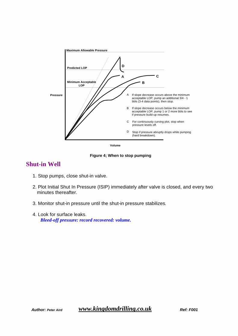
A: If slope decrease occurs above minimum acceptable leak-off pressure, pump an additional 3/4 to 1 bbl (another 3 to 4 data points), then stop.
B: If slope decrease occurs below minimum acceptable leak-off pressure, pump one or two more bbls to see if pressure will resume building. If pressure resumes building, return to Case A. C: If plot continuously curves, stop when pressure levels off (3 to 4 points at roughly the same pressure).
D: Stop if the pressure abruptly drops while pumping (hard breakdown).
Author: Peter Aird www.kingdomdrilling.co.uk Ref: F001
Pressure
Volume
Predicted LOP
Minimum Acceptable LOP
Maximum Allowable Pressure
A
B
D
C
For continuously curving plot, stop when pressure levels off.
C
If slope decrease occurs above the minimum acceptable LOP, pump an additional 3/4 - 1 bbls (3-4 data points), then stop.
A
If slope decrease occurs below the minimum acceptable LOP, pump 1 or 2 more bbls to see if pressure build-up resumes.
B
Stop if pressure abruptly drops while pumping (hard breakdown).
D
Figure 4; When to stop pumping
Shut-in Well
1. Stop pumps, close shut-in valve. 2. Plot Initial Shut In Pressure (ISIP) immediately after valve is closed, and every two
minutes thereafter. 3. Monitor shut-in pressure until the shut-in pressure stabilizes. 4. Look for surface leaks.
Bleed-off pressure: record recovered: volume.
Author: Peter Aird www.kingdomdrilling.co.uk Ref: F001
Data interpretation Record Measured Depth (MD), True Vertical Depth (TVD), Azimuth and Inclination of the well at the shoe (top of first sand for open hole LOT). Also record pump rate, volume pumped, volume recovered, casing size, and mud properties from the morning report (mud weight, WBM or OBM, LC material, PV, YP, etc.)
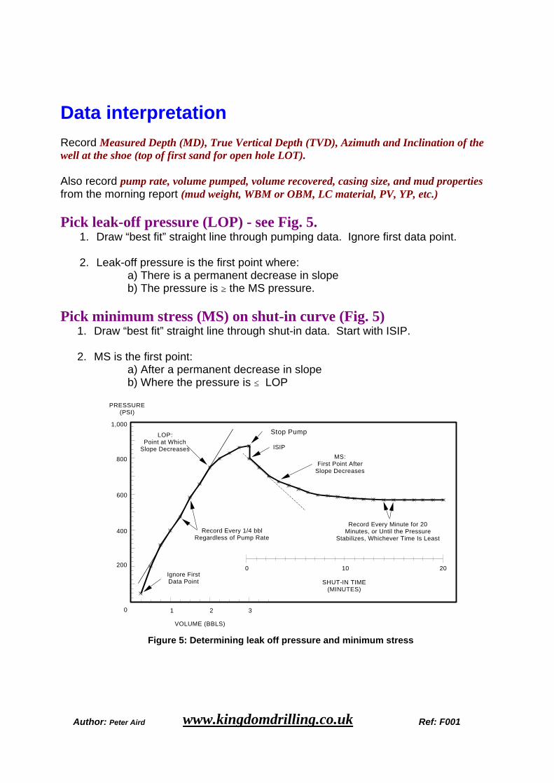
Pick leak-off pressure (LOP) - see Fig. 5. 1. Draw “best fit” straight line through pumping data. Ignore first data point. 2. Leak-off pressure is the first point where:
a) There is a permanent decrease in slope b) The pressure is ≥ the MS pressure.
Pick minimum stress (MS) on shut-in curve (Fig. 5) 1. Draw “best fit” straight line through shut-in data. Start with ISIP. 2. MS is the first point:
a) After a permanent decrease in slope b) Where the pressure is ≤ LOP
0 1 2 3
200
400
600
800
1,000
VOLUME (BBLS)
PRESSURE (PSI)
SHUT-IN TIME (MINUTES)
Stop Pump
ISIP
LOP: Point at Which
Slope Decreases
Ignore First Data Point
Record Every Minute for 20 Minutes, or Until the Pressure
Stabilizes, Whichever Time Is Least
Record Every 1/4 bbl Regardless of Pump Rate
10 0 20
MS: First Point After
Slope Decreases
Figure 5: Determining leak off pressure and minimum stress
Author: Peter Aird www.kingdomdrilling.co.uk Ref: F001
3. Compute equivalent mud weights (ppg) for leak-off pressure and minimum stress:
LOPEMW = MW + LOP/(0.052*TVD) MSEMW = MW + MS/(0.052*TVD) where MW is the mud weight (ppg) in the hole at the time of the leak-off test, and TVD is true vertical depth to the casing shoe (top of first sand for open hole LOT).
4. Evaluate the cement job. Cement channels may be indicated by any of the following:
1. LOPEMW is below the equivalent mud weight for the minimum acceptable leak- off pressure
2. LOPEMW / MSEMW ≥ 1.10.
3. Shut-in pressure not levelling off (in shale) Keep in mind that the LOP at the shoe could be less than the LOP that is needed. If the minimum stresses measured before and after a squeeze are similar, the squeeze was wasted, even if the LOP went up. Similar minimum stresses mean the same formation is taking fluid. Either:
1. The channel was not repaired, or 2. There is no channel, and the targeted LOP is unrealistic.
Retesting
ALWAYS retest before squeeze
1. Use same mud weight, pump rate. 2. Channel confirmed when retest shows no improvement.
Retest to confirm minimum stress measurement Test again if results vary significantly from previous test. Retest if pressure abruptly dropped significantly while pumping (hard break-down) to determine a valid LOP. Do not use the peak pressure as the LOP.
Author: Peter Aird www.kingdomdrilling.co.uk Ref: F001
Difference from standard L.O.T. procedures
1. Consistently collect three to four data points after leak-off before pump is stopped. 2. Monitor shut-in pressure for twenty minutes, or until the pressure stabilizes,
whichever time is least.
3. Repeat test before squeezing to confirm presence of channel; also repeat test to confirm minimum stress measurement.
4. Use accurate surface gauges to measure pressure
- do not rely on standard rig gauge.
5. Install shut-in valve between cement pump and pressure gauge; do not rely on the pump to hold pressure.