Embed Size (px)
Citation preview
LEAKAGE CURRENT TESTER
GLC-9000
QUICK START GUIDE GWINSTEK PART NO.:82LC-90000MB1
ISO-9001 CERTIFIED MANUFACTURER
This manual contains proprietary information, which is protected by copyright. All rights are reserved. No part of this manual may be photocopied, reproduced or translated to another language without prior written consent of Good Will Corporation.
The information in this manual was correct at the time of printing. However, Good Will continues to improve its products and therefore reserves the right to change the specifications, equipment, and maintenance procedures at any time without notice.
Good Will Instrument Co., Ltd. No. 7-1, Jhongsing Rd., Tucheng City, Taipei County 236, Taiwan.
Table of Contents
3
Table of Contents INTRODUCTION .............................................. 5 Introduction ........................................................................ 5 Front Panel .......................................................................... 6 Rear Panel ........................................................................... 8 Leakage Current Modes ....................................................... 9 Key Features ...................................................................... 10 Power and Probe Connection ............................................. 14 Preparation ....................................................................... 17 Interface ............................................................................ 19
OPERATION ................................................... 23 Measurement Terminals .................................................... 23
Non-medical Network (General Electrical Appliance) ........ 23 Medical Equipment .............................................................. 24
Leakage Current Testing Connections ................................ 25
OTHER ........................................................... 29 EUT Voltage and Current Check ......................................... 29 Voltage Measurement ........................................................ 30

4
INTRODUCTION
5
INTRODUCTION This quick start guide is designed to help those who are not familiar with the GLC-9000 to quickly learn the fundamentals. For details on system settings, parameter settings, save/recall, remote instructions and other operation features and functions, please refer to the user manual.
Introduction
Overview This quick start guide provides the basics on:
Front and rear panels with descriptions of all features and functions on the panels
Description of the Leakage current modes
Basic preparation and power up
Main screen display overview
Summaries of the different leakage current measurement operations
Summary of the EUT Voltage and Current Check function and the Voltage Meter function.
GLC-9000 Quick Start Guide
6
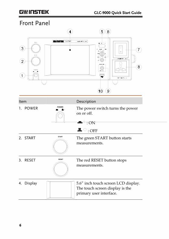
Front Panel
Item Description
1. POWER
The power switch turns the power on or off.
: ON
: OFF
2. START
The green START button starts measurements.
3. RESET
The red RESET button stops measurements.
4. Display
5.6” inch touch screen LCD display. The touch screen display is the primary user interface.
INTRODUCTION
7
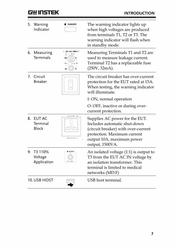
5. Warning Indicator
The warning indicator lights up when high voltages are produced from terminals T1, T2 or T3. The warning indicator will flash when in standby mode.
6. Measuring Terminals
Measuring Terminals T1 and T2 are used to measure leakage current. Terminal T2 has a replaceable fuse (250V, 32mA).
7. Circuit Breaker
The circuit breaker has over-current protection for the EUT rated at 15A. When testing, the warning indicator will illuminate.
I: ON, normal operation
O: OFF, inactive or during over-current protection.
8. EUT AC Terminal Block
Supplies AC power for the EUT. Includes automatic shut-down (circuit breaker) with over-current protection. Maximum current output 10A, maximum power output, 1500VA.
9. T3 110% Voltage Application
An isolated voltage (1:1) is output to T3 from the EUT AC IN voltage by an isolation transformer. This terminal is limited to medical networks (MD:F)
10. USB HOST
USB host terminal.
GLC-9000 Quick Start Guide
8
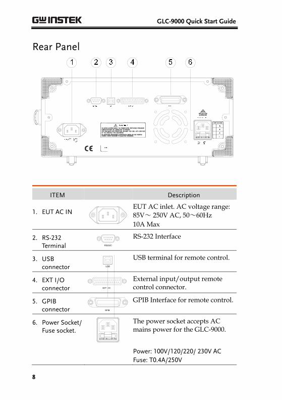
Rear Panel
ITEM Description
1. EUT AC IN
EUT AC inlet. AC voltage range: 85V~ 250V AC, 50~60Hz 10A Max
2. RS-232 Terminal RS232C
RS-232 Interface
3. USB connector USB
USB terminal for remote control.
4. EXT I/O connector EXT I/O
External input/output remote control connector.
5. GPIB connector GPIB
GPIB Interface for remote control.
6. Power Socket/ Fuse socket.
The power socket accepts AC mains power for the GLC-9000.
Power: 100V/120/220/ 230V AC Fuse: T0.4A/250V
INTRODUCTION
9
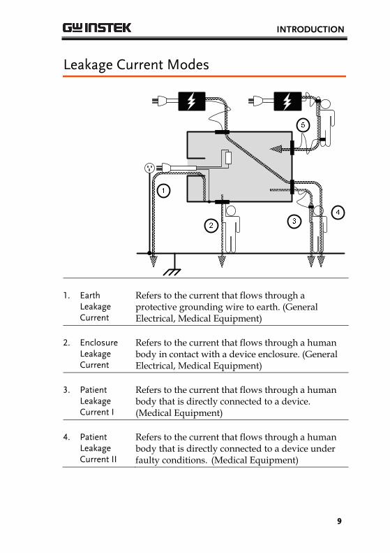
Leakage Current Modes
1. Earth Leakage Current
Refers to the current that flows through a protective grounding wire to earth. (General Electrical, Medical Equipment)
2. Enclosure Leakage Current
Refers to the current that flows through a human body in contact with a device enclosure. (General Electrical, Medical Equipment)
3. Patient Leakage Current I
Refers to the current that flows through a human body that is directly connected to a device. (Medical Equipment)
4. Patient Leakage Current II
Refers to the current that flows through a human body that is directly connected to a device under faulty conditions. (Medical Equipment)
GLC-9000 Quick Start Guide
10
5. Patient Leakage Current III
Refers to the current that flows through a human body that is directly connected to a device that malfunctions. (Medical Equipment)
6. Patient Auxiliary Current
Refers to the current that flows through a human and a device during normal operation. This is not intended to be perceptive. (Medical Equipment)
Key Features
International Standards and Regulations
The GLC-9000 has nine measurement networks (Measuring Devices: MD) supporting GB/12113, IEC/UL and other international standards for electrical products: (1) MD-A:IEC60990 (2) MD-B:IEC60990 (3) MD-C:IEC60990 (4) MD-D:UL (5) MD-E(1kΩ):-general application (6) MD-F: Medical (7) MD-G:UL (8) MD-H:(2kΩ)-general application (9) MD-I:JIS
INTRODUCTION
11
Measurement Modes
There are a number of leakage current measurement tests covering general electrical equipment and medical electrical equipment.
(1) Earth Leakage Current. (2) Leakage current from enclosure and earth. (3) Leakage current from enclosure to enclosure. (4) Leakage current from enclosure to line. (5) Patient Auxiliary Current*. (6) Patient leakage current I*. (7) Patient leakage current II*. (8) Patient leakage current III*.
*Tests 5,6,7,8 are applicable to medical MD-F devices.
Leakage Current Types
Leakage current measurement modes: DC, AC, AC+DC, AC Peak.
Measurement Range
Automatic/Manual ranges: DC/AC/AC+DC:50uA/500uA/5mA/25mA (Range:4uA~25mA) AC Peak:500uA/1mA/10mA/75mA (Range:40uA~75mA)
GLC-9000 Quick Start Guide
12
Operation Auto/Manual/Programmable Single fault conditions and power supply polarity switch
Measurement/Delay time settings
Maximum / minimum hold
PASS/FAIL(Upper, Lower) Judgement (limits)
save and recall setup and measurement results
System clock settings
Multilanguage support
System Self test
EUT voltage/current/power consumption
High output alarm and led indicators.
Remote control interface options
Interface With the exception of the Start, Reset and power switches, the user-interface is entirely controlled via a touch screen.
LCD The simple, user-friendly interface is extremely intuitive with a large 5.6” color TFT screen.
EUT Test Status The voltage, current and power consumption of the EUT can be measured.
Built-in Voltage Meter
The built in voltage meter detects 0-300V. The voltage meter is activated when the Safety Extra Low Voltage (SELV) function is on.
Memory 30 sets of memory for user defined test conditions
50 sets of standard test conditions. (e.g., IEC60990)
100 sets of measurements can be saved/recalled
INTRODUCTION
13
Remote Interface There are a variety of remote control interfaces including: RS-232, USB (Host/Device), GPIB and the EXT I/O connector.
Protection The LED warning indicator will illuminate and emit a tone by default for:
Judgment limits. (high/low limits).
High Voltages output from the testing terminals.
Overload protection (fuse protection).
Relay protection for EUT overloads.
GLC-9000 Quick Start Guide
14
Power and Probe Connection
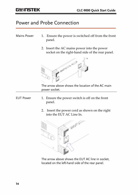
Mains Power 1. Ensure the power is switched off from the front panel.
2. Insert the AC mains power into the power socket on the right-hand side of the rear panel.
The arrow above shows the location of the AC main power socket.
EUT Power 1. Ensure the power switch is off on the front panel.
2. Insert the power cord as shown on the right into the EUT AC Line In.
The arrow above shows the EUT AC line in socket, located on the left-hand side of the rear panel.
INTRODUCTION
15
Caution If network B (MD B) is selected an isolation transformer that outputs 110% of the rated voltage specified for the EUT is required. The neutral line must be grounded (from the secondary side of the transformer).
Measurement networks (MD)A, B, C all require an isolation transformer.
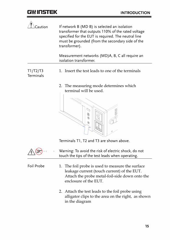
T1/T2/T3 Terminals
1. Insert the test leads to one of the terminals
2. The measuring mode determines which
terminal will be used.
Terminals T1, T2 and T3 are shown above.
Warning: To avoid the risk of electric shock, do not touch the tips of the test leads when operating.
Foil Probe 1. The foil probe is used to measure the surface leakage current (touch current) of the EUT. Attach the probe metal-foil-side down onto the enclosure of the EUT.
2. Attach the test leads to the foil probe using
alligator clips to the area on the right, as shown in the diagram
GLC-9000 Quick Start Guide
16
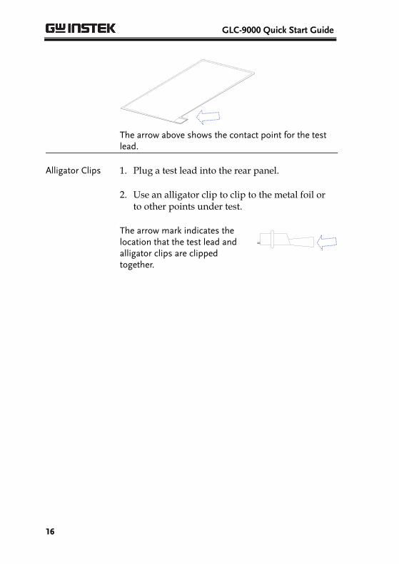
The arrow above shows the contact point for the test lead.
Alligator Clips 1. Plug a test lead into the rear panel.
2. Use an alligator clip to clip to the metal foil or
to other points under test.
The arrow mark indicates the location that the test lead and alligator clips are clipped together.
INTRODUCTION
17
Preparation
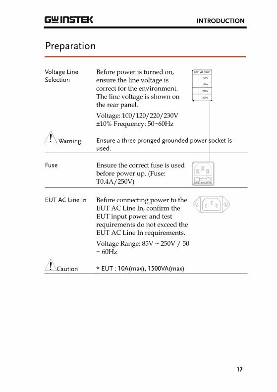
Voltage Line Selection
Before power is turned on, ensure the line voltage is correct for the environment. The line voltage is shown on the rear panel.
Voltage: 100/120/220/230V ±10% Frequency: 50~60Hz
120V
100V
220V
230V
Warning Ensure a three pronged grounded power socket is used.
Fuse Ensure the correct fuse is used before power up. (Fuse: T0.4A/250V)
EUT AC Line In
Before connecting power to the EUT AC Line In, confirm the EUT input power and test requirements do not exceed the EUT AC Line In requirements.
Voltage Range: 85V ~ 250V / 50 ~ 60Hz
Caution * EUT : 10A(max), 1500VA(max)
GLC-9000 Quick Start Guide
18
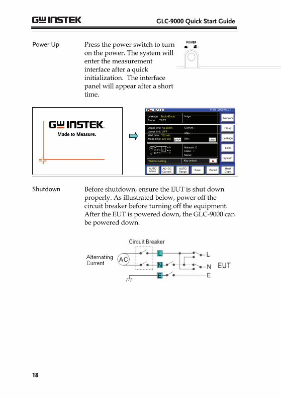
Power Up Press the power switch to turn on the power. The system will enter the measurement interface after a quick initialization. The interface panel will appear after a short time.
Max :
Min:
Name:
Class: I Network: E
Wait for setting…
Save Recall Hard Copy
Network
Class
Leakage
Limit
System
AC+DCCurrent
AUTO Meas
AUTORange
14:58 2009.09.01
Leakage: Enclo-Enclo
Probe: T1/T2
Current :
Judge:
Lower limit: OFF Wait time: 120 sec
Upper limit: 12.00mA
Meas time: 220 sec
AC+DC Current
cleargraph
Key unlock
Shutdown Before shutdown, ensure the EUT is shut down properly. As illustrated below, power off the circuit breaker before turning off the equipment. After the EUT is powered down, the GLC-9000 can be powered down.
INTRODUCTION
19
Interface
Max :
Min:
Name:
10.10 mA
Class: I Network: E
Save Recall Hard Copy
Network
Class
Leakage
Limit
System
AC+DCCurrent
AUTOMeas
AUTORange
14:58 2009.09.01
UFAILLeakage: Enclo-Enclo
Probe: T1/T2
Current :
10.00 uA
Judge:
10mA
OFF 12.10 mA
AC+DC Current
Ready…
graph clear
Key unlock
Main Display
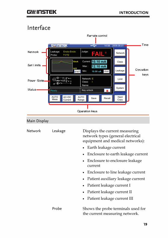
Network Leakage Displays the current measuring network types (general electrical equipment and medical networks):
Earth leakage current
Enclosure to earth leakage current
Enclosure to enclosure leakage current
Enclosure to line leakage current
Patient auxiliary leakage current
Patient leakage current I
Patient leakage current II
Patient leakage current III
Probe Shows the probe terminals used for the current measuring network.
GLC-9000 Quick Start Guide
20
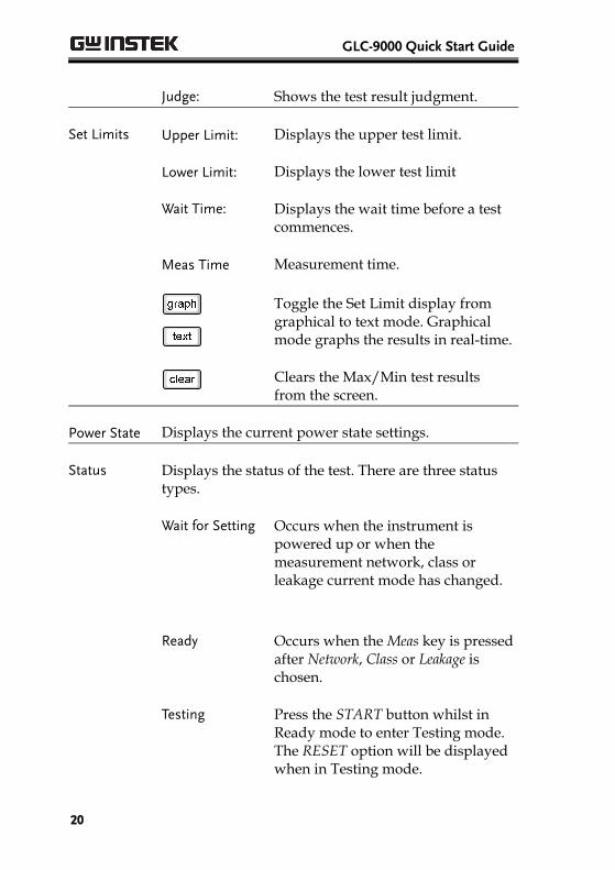
Judge: Shows the test result judgment.
Set Limits Upper Limit: Displays the upper test limit.
Lower Limit: Displays the lower test limit
Wait Time: Displays the wait time before a test commences.
Meas Time Measurement time.
Toggle the Set Limit display from graphical to text mode. Graphical mode graphs the results in real-time.
Clears the Max/Min test results from the screen.
Power State Displays the current power state settings.
Status Displays the status of the test. There are three status types.
Wait for Setting Occurs when the instrument is powered up or when the measurement network, class or leakage current mode has changed.
Ready
Occurs when the Meas key is pressed after Network, Class or Leakage is chosen.
Testing
Press the START button whilst in Ready mode to enter Testing mode. The RESET option will be displayed when in Testing mode.
INTRODUCTION
21
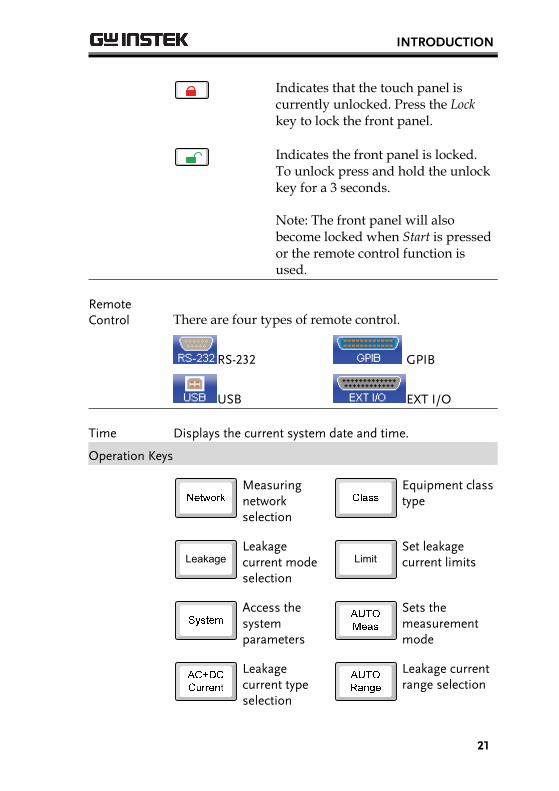
Indicates that the touch panel is currently unlocked. Press the Lock key to lock the front panel.
Indicates the front panel is locked. To unlock press and hold the unlock key for a 3 seconds.
Note: The front panel will also become locked when Start is pressed or the remote control function is used.
Remote Control There are four types of remote control.
RS-232 GPIB
USB EXT I/O
Time Displays the current system date and time.
Operation Keys
Measuring network selection
Equipment class type
Leakage
Leakage current mode selection
Limit
Set leakage current limits
Access the system parameters
Sets the measurement mode
Leakage current type selection
Leakage current range selection
GLC-9000 Quick Start Guide
22
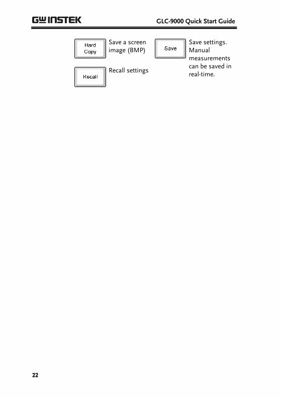
Save a screen image (BMP)
Save settings. Manual measurements can be saved in real-time.
Recall settings
OPERATION
23
OPERATION
Measurement Terminals
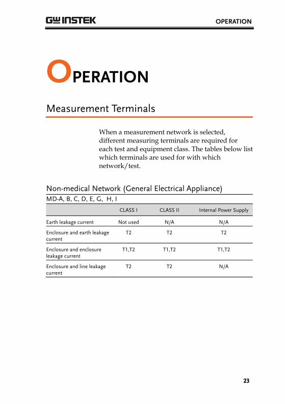
When a measurement network is selected, different measuring terminals are required for each test and equipment class. The tables below list which terminals are used for with which network/test.
Non-medical Network (General Electrical Appliance) MD-A, B, C, D, E, G, H, I
CLASS I CLASS II Internal Power Supply
Earth leakage current Not used N/A N/A
Enclosure and earth leakage current
T2 T2 T2
Enclosure and enclosure leakage current
T1,T2 T1,T2 T1,T2
Enclosure and line leakage current
T2 T2 N/A
GLC-9000 Quick Start Guide
24
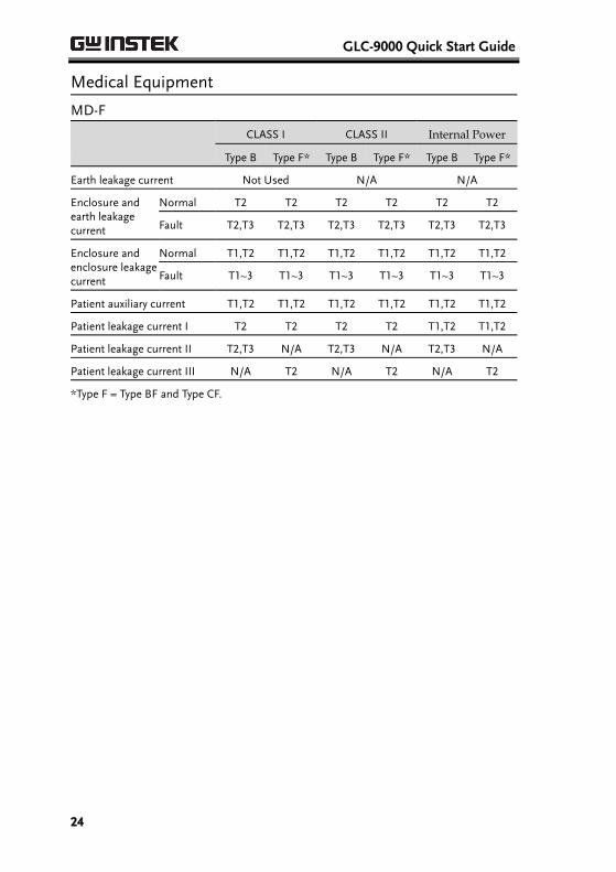
Medical Equipment
MD-F
CLASS I CLASS II Internal Power
Type B Type F* Type B Type F* Type B Type F*
Earth leakage current Not Used N/A N/A
Enclosure and earth leakage current
Normal T2 T2 T2 T2 T2 T2
Fault T2,T3 T2,T3 T2,T3 T2,T3 T2,T3 T2,T3
Enclosure and enclosure leakage current
Normal T1,T2 T1,T2 T1,T2 T1,T2 T1,T2 T1,T2
Fault T1~3 T1~3 T1~3 T1~3 T1~3 T1~3
Patient auxiliary current T1,T2 T1,T2 T1,T2 T1,T2 T1,T2 T1,T2
Patient leakage current I T2 T2 T2 T2 T1,T2 T1,T2
Patient leakage current II T2,T3 N/A T2,T3 N/A T2,T3 N/A
Patient leakage current III N/A T2 N/A T2 N/A T2
*Type F = Type BF and Type CF.
OPERATION
25
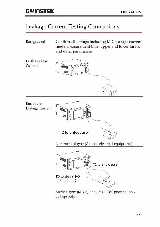
Leakage Current Testing Connections
Background Confirm all settings including MD, leakage current mode, measurement time, upper and lower limits, and other parameters.
Earth Leakage Current
Enclosure Leakage Current
Non-medical type (General electrical equipment)
Medical type (MD-F) Requires 110% power supply voltage output.
GLC-9000 Quick Start Guide
26
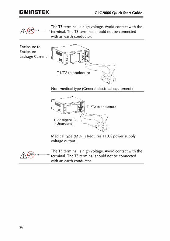
The T3 terminal is high voltage. Avoid contact with the terminal. The T3 terminal should not be connected with an earth conductor.
Enclosure to Enclosure Leakage Current
Non-medical type (General electrical equipment)
Medical type (MD-F) Requires 110% power supply voltage output.
The T3 terminal is high voltage. Avoid contact with the terminal. The T3 terminal should not be connected with an earth conductor.
OPERATION
27
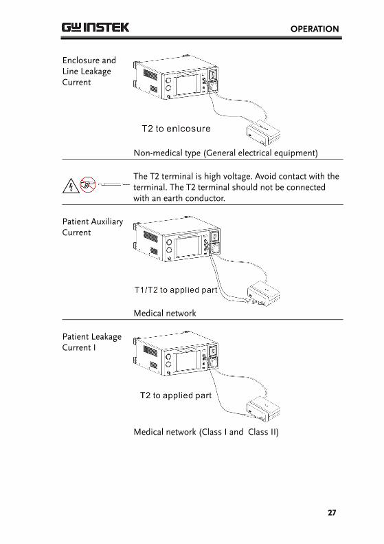
Enclosure and Line Leakage Current
Non-medical type (General electrical equipment)
The T2 terminal is high voltage. Avoid contact with the terminal. The T2 terminal should not be connected with an earth conductor.
Patient Auxiliary Current
Medical network
Patient Leakage Current I
Medical network (Class I and Class II)
GLC-9000 Quick Start Guide
28
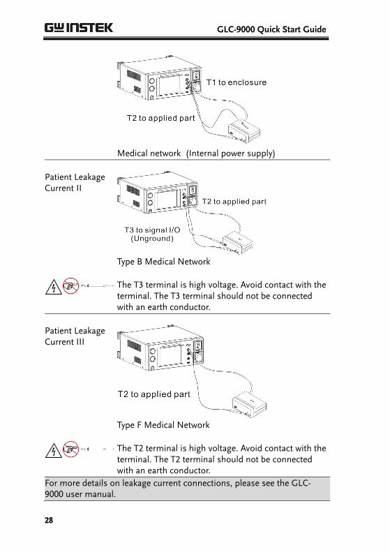
Medical network (Internal power supply)
Patient Leakage Current II
Type B Medical Network
The T3 terminal is high voltage. Avoid contact with the terminal. The T3 terminal should not be connected with an earth conductor.
Patient Leakage Current III
Type F Medical Network
The T2 terminal is high voltage. Avoid contact with the terminal. The T2 terminal should not be connected with an earth conductor.
For more details on leakage current connections, please see the GLC-9000 user manual.
OTHER
29
OTHER
EUT Voltage and Current Check
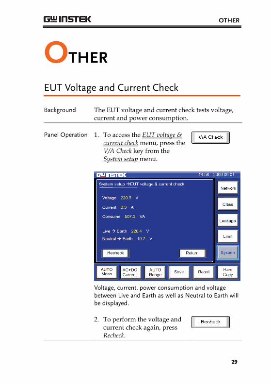
Background The EUT voltage and current check tests voltage, current and power consumption.
Panel Operation 1. To access the EUT voltage & current check menu, press the V/A Check key from the System setup menu.
Voltage, current, power consumption and voltage between Live and Earth as well as Neutral to Earth will be displayed.
2. To perform the voltage and current check again, press Recheck.
GLC-9000 Quick Start Guide
30
Voltage Measurement
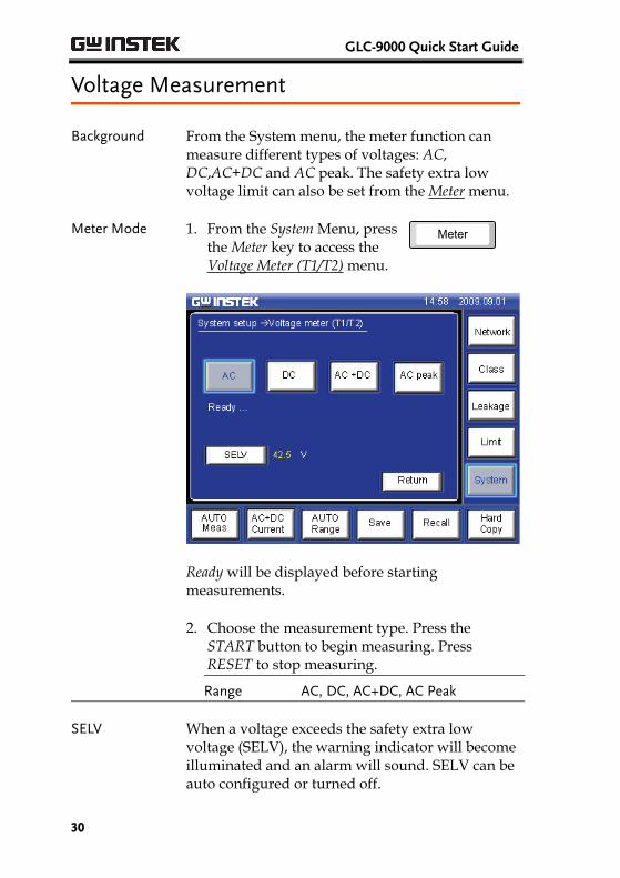
Background From the System menu, the meter function can measure different types of voltages: AC, DC,AC+DC and AC peak. The safety extra low voltage limit can also be set from the Meter menu.
Meter Mode 1. From the System Menu, press the Meter key to access the Voltage Meter (T1/T2) menu.
Meter
Ready will be displayed before starting measurements.
2. Choose the measurement type. Press the START button to begin measuring. Press RESET to stop measuring.
Range AC, DC, AC+DC, AC Peak
SELV When a voltage exceeds the safety extra low voltage (SELV), the warning indicator will become illuminated and an alarm will sound. SELV can be auto configured or turned off.
OTHER
31
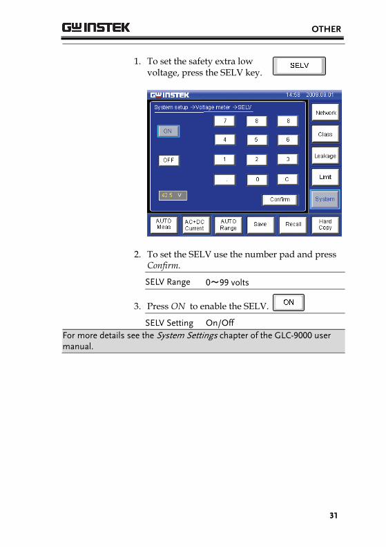
1. To set the safety extra low voltage, press the SELV key.
2. To set the SELV use the number pad and press Confirm.
SELV Range 0~99 volts
3. Press ON to enable the SELV.
SELV Setting On/Off For more details see the System Settings chapter of the GLC-9000 user manual.