Embed Size (px)
Citation preview

[email protected] [email protected]
JOURNAL of NUCLEAR And Related TECHNOLOGIES (JNRT). Volume 11. No. 1, June, 2014.
LEAKAGE RADIATION DOSE ANALYSIS AT ELV-4BUNKER'S DOOR
Mohd Rizal Md Chulan1*; Redzuwan Yahaya1*; Abu Bakar Mhd Ghazali2
'School of Applied Physics, Faculty of Science and Technology, Universiti Kebangsaan Malaysia,1Department of Electronic and Communication, College of Engineering, Universiti Tenaga Nasional.
*Corresponding author:_;_
ABSTRACT
Bunker Shielding is most important in the safety of an accelerator and one of the most important
aspects of this shielding is the door. The bunker's door have be properly designed to minimize the
leakage radiation and shall not exceed the permitted limit of 2.5pSv/hr. In such a bunker, the leakageradiation doses were estimated using the radiation protection concept and the data provided by
machine supplier (BINP). The radiation leakage outside the bunker was determined through direct
measurement using a survey meter. It was found thai there were leakage radiation doses that have
exceeded the permitted limit of 2.5/aSv/hr at the gap between the bunker's door and the wall, with the
highest found to be at the labeled location 10 which were f66.6f7pSv/hr (from, the calculation) and
f79.573p.Sv/hr (from direct measurement). This high leakage radiation dose was due to the lack ofsignificant thickness in the bunker's door of the shielding and the size of the gaps between the door
and the wall. Thus modification and improvement to the shielding need to be done in order to protect
workers and the public whilst the accelerator is in operation.
ABSTRAK
Perisaian Bunker merupakan aspek keselamatan terpenting dalam suatu pemecut dan salah satu
bahagian tersebut. gang paling penting adalah pintu. Pintu bunker ini perlu. direkabent.uk dengan teliti
supaya dos sinaran yang melaluinya, dikenali sebagai dos sinaran bocor adalah tidak melebihi had
yang ditetapkan iaitu. 2.5pSv/j. Dos sinaran bocor telah dianggarkan menggu.nakan konsepperlindungan sinaran dan ju.ga data yang disediakan oleh pembekal alat (BINP). Sementara, dos
sinaran bocor pad.a lu.ar pintu bunker ini juga telah diperolehi dengan pengu.kuran terns menggunakanmeter tinjau.. Daripada analisa melalu.i pengiraan dan pengu.kuran terus, didapati terdapat dos sinaran
bocor yang melebihi had yang ditetapkan (2.5pSv/j) iaitu. pada riming antara pintu dan dinding bunkerdengan dos sinaran bocor tertinggi. pada lokasi bertanda 10 iaitu f66.6f7pSv/j (daripada pengiraan)dan f79.573pSv/j (daripada pengu.kuran. teru.s). Dos .sinaran bocor yang tinggi ini didapati berpunca
daripada ketebalan berkesan pintu (perisai) yang tidak mencukupi dan saiz celahan antara pintu dandinding bunker tersebut. Oleh itu pengubahsuaian dan penambahbaikan kepada perisaian perludilakukan bagi melindungi pekerja dan orang awam. semasa pemecut sedang beroperasi.
Keywords: Leakage radiation dose, shielding calculation, accelerator bunker, electronaccelerator.
81

JOURNAL of NUCLEAR And Related TECHNOLOGIES (JNRT). Volume 11. No. 1, June, 2014.
INTRODUCTION
ELV-4 is an electron accelerator acquired by Malaysian Nuclear Agency from Budker Institute of Nuclearphysics or BINP, Russia. The equipment was acquired for the purpose of radiating cables, thin films and
sewage wastewater treatment. It has a maximum power of 50kW with maximum energy of lMeV and beamcurrents of 50mA. The electron generated, when interacting with the main metal components will produce x-
rays i.e. bremsstrahlung. As such, a shielding construction known as bunker, with a dimension of 5m (width) x
5m (breadth) x 4m (height) was design and constructed in siting the ELV-4 equipment. The leakage radiationdose limit for the bunker was set at 2.5pSv/hr, which is the exposure at the surface of the door on the outsideof the bunker. The thickness of the bunker wall was built with Grade 40 reinforced concrete (density >2.3g/cm3) as calculated by Abu Bakar Ghazali et al. (2006) with a suggested thickness of 120cm. The same
thickness was taken for the door. The problem exist when looking at the door as a whole where there are gaps
between the door and the wall of the bunker which could allow radiation to pass through that resulted in
leakage radiation dose outside the bunker.
This paper discussed the leakage radiation dose values, where radiation passed through the gaps between thedoor and the wall of the bunker at the labeled location as shown as Figure 1. The leakage radiation doseoutside the bunker was estimated using the method shown by Abu Bakar et al. (2006). These calculatedresults were then compared to the measurement results using Ludlum Model 3 with Probe Model 44-9(G.M).
Theoretical Aspects
The bremsstrahlung radiation is produced when an electron beam impinges on the metal target (iron) as
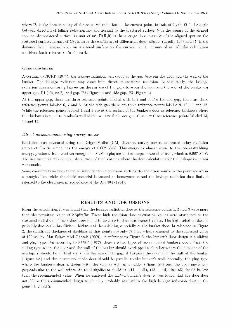
shown in Figure 4. The bremsstrahlung radiation will move from the target to the entire space and to thebunker's wall. The intensity of the absorbed dose in the air for the angle and the distance R, P(R, ) can becalculated by the following the equation:
where P(R, ) is the effective dose intensity at the current point, unit of rad.nr.min"1; Po( ) is the absorbed
dose intensity in air at a distance of 1 m from the beam of energy 1.0 MeV and beam current 50 mA and is
stopped by the Fe target with angle distributions of bremsstrahlung. unit of Gy nr/h; and with R the
distance from target to current point, in unit of m.
The radiation on the wall will penetrate or will be scattered. The penetrated radiation after the shielding can
be calculated using the equation:
where Pshidd is the dose intensity at the current point after shielding (which decreases through shielding), in
unit of Gy/h; P(R, ) is the dose intensity at the current point without shielding, in unit of Gy/h; p is
attenuation coefficient that depends on the electron energy and material (atomic number) used, in unit of m"1and t is the thickness of shielding.
For the scattered radiation, the dose intensity of the scattered radiation can also be calculated using thefollowing equation:
METHODOLOGY
Pshield = P(R, )
Ps = (J x P(R, ) x S x cos
82
JOURNAL of NUCLEAR And Related TECHNOLOGIES (JNRT). Volume 11. No. 1, June, 2014.
where Ps is the dose intensity of the scattered radiation at the current point, in unit of Gy/h; is the anglebetween direction of falling radiation ray and normal to the scattered surface; S is the square of the aligned
spot on the scattered surface, in unit of m2; P(R, ) is the average dose intensity of the aligned spot on thescattered surface, in unit of Gy/h; J is the coefficient of differential dose 'albedo' (usually f(f2) and R' is thedistance from aligned spot on scattered surface to the current point, in unit of m. All the calculationconsideration is referred to in Figure 4.
Gaps considered
According to NCRP (1977), the leakage radiation can occur at the gap between the door and the wall of thebunker. The leakage radiation may come from direct or scattered radiation. In this study, the leakageradiation dose monitoring focuses on the surface of the gaps between the door and the wall of the bunker e.g
upper gap, PI (Figure 2), end gap, P2 (Figure 3) and side gap, P3 (Figure 3)
At the upper gap, there are three reference points labeled with 1, 2 and 3. For the end gap, there are threereference points labeled 6, 7 and 8. At the side gap there are three reference points labeled 9, 10, 11 and 12.
While the reference points labeled 4 and -5 are at the surface of the bunker's door as reference thickness wherethe thickness is equal to bunker's wall thickness. For the lower gap, there are three reference points labeled 13,14 and 15.
Direct measurement using survey meter
Radiation was measured using the Geiger Muller (GM) detector, survey meter, calibrated using radiationsource of Gs-137 which has the energy of 0.662 MeV. This energy is almost equal to the bremsstrahlungenergy, produced from electron energy of 1MeV impinging on the target material of iron, which is 0.667 MeV.The measurement was done at the surface of the locations where the dose calculations for the leakage radiationwere made.
Some considerations were taken to simplify the calculations such as the radiation source is the point source in
a straight line, while the shield material is treated as homogeneous and the leakage radiation dose limit is
referred to the clean area in accordance of the Act 304 (1984).
RESULTS AND DISCUSSIONS
From the calculation, it was found that the leakage radiation dose at the reference points 1, 2 and 3 were more
than the permitted value of 2.5pSv/hr. These high radiation dose calculation values were attributed to thescattered radiation. These values were found to be close to the measurement values. The high radiation dose is
probably due to the insufficient thickness of the shielding especially at the bunker door. In reference to Figure
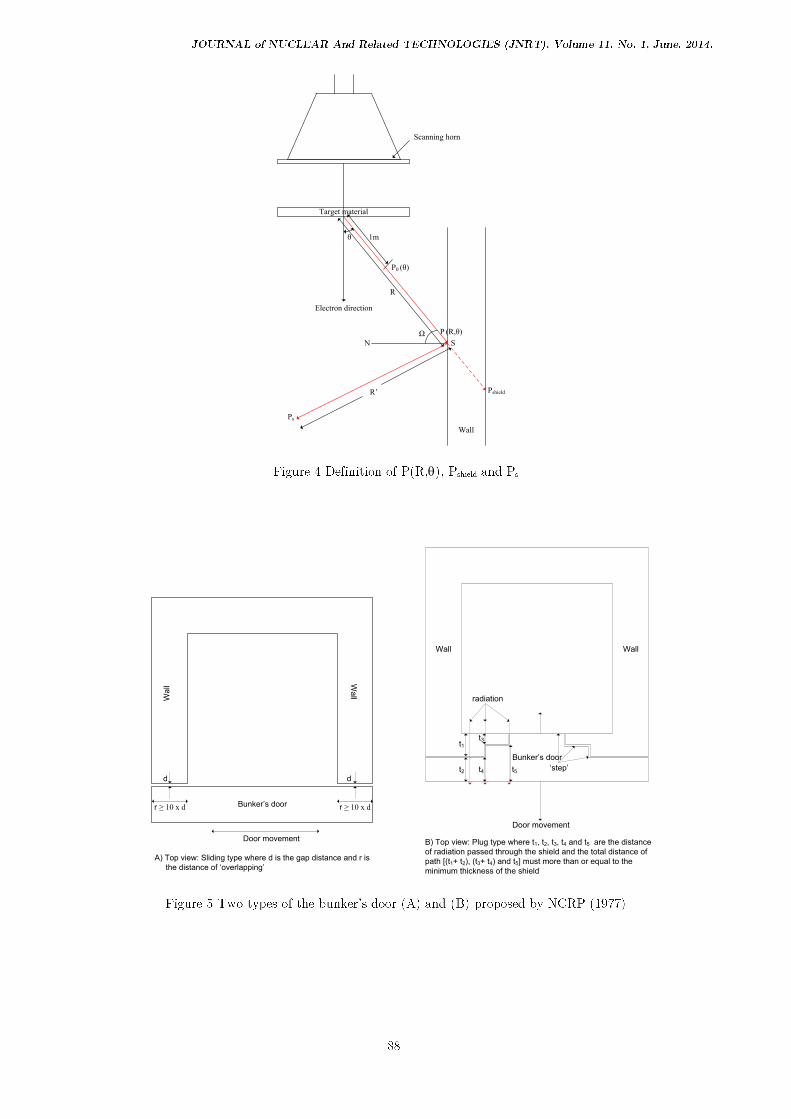
2, the significant thickness of shielding at that points are only 37.5 cm when compared to the suggested valueof 120 cm by Abu Bakar Mhd Ghazali (2009). In reference to Figure 3, the bunker's door design is a slidingand plug type. But according to NCRP (1977), there are two types of recommended bunker's door. First, thesliding type where the door and the wall of the bunker should overlapped each other where the distance of theoverlap, r should be at least ten times the size of the gap, d between the door and the wall of the bunker
(Figure 5A) and the movement of the door should be parallel to the bunker's wall. Secondly, the plug type
where the bunker's door is design with the step as well as a ladder (Figure 5B) and the door movement
perpendicular to the wall where the total significant shielding [(tl + t2), (t3 + t,4) dan t5] should be lessthan the recommended value. When we analysed the ELV-4 bunker's door, it was found that the door doesnot follow the recommended design which may probably resulted in the high leakage radiation dose at thepoints I, 2 and 3.
83

JOURNAL of NUCLEAR And Related TECHNOLOGIES (JNRT). Volume 11. No. 1, June, 2014.
Table 1 Absorbed dose intensity, Po( ) versus
o 0 10 20 30 40 50 60 70 80 90
Po( ) 1740 1530 1266 954 864 690 582 450 342 135
o 100 110 120 130 140 150 160 170 180
Po( ) 195 250 290 290 290 234 210 210 185
The different values between the calculation and the direct measurement for the reference points 1, 2 and 3
were probably caused by the size of the upper gap, d (Figure 2). The gap size of the conceptual drawing from
A Bakar Ghazali (2009) is 25 mm width, but the real gap size at those points is 30 mm to 40 mm. This is dueto the unequal concrete surface thickness of the bunker's wall which would allow more radiation to pass
through and resulted in the high radiation at the gap surface.
The leakage radiation dose calculation for the reference points 6, 7 and 8 showed the radiation dose to behigher than the permitted value of 2.5pSv/hr which was attributed to the same arguments as for the points 1,2 and 3 above.
The differences between the calculated and direct measurement values for the reference points 6, 7 and 8 were
due to the different sizes of the end gap used in the calculation when compared to the real gap size. The gap
size in the calculation is 25 mm, obtained from conceptual drawing by A Bakar Ghazali (2009) while in thereal situation, the door and the wall of the bunker almost touched each other especially for reference point 7.This small gap size will allow less radiation dose to pass through and will results in the leakage radiation dosebeing lower than the permissible limit.
Table 2 Calculated and Measurement Results
Location Calculation (pSv/hr) Direct measurement
Directradiation
Scatteredradiation
(liSv/hr)
1 0.032 14.297 22.745
2 0.197 18.848 43.042
3 0.373 20.722 61.222
4 0.316 0.007 0.000
5 0.265 0.006 0.000
6 0.345 38.119 17.237
7 0.426 43.685 0.466
8 0.188 42.483 9.097
9 0.003 104.140 102.593
10 0.019 466.647 479.573
11 0.009 1.322 0.446
12 0.012 1.180 4.009
13 0.074 2.446 0.252
84

JOURNAL of NUCLEAR And Related TECHNOLOGIES (JNRT). Volume 11. No. 1, June, 2014.
14 0.009 0.660 0.272
15 0.001 55.660 26.863
Note: The blue values show leakage radiation doses that were lower than the permitted value of 2.5pSv/hr.
Base on the result of the direct measurements, eventhough the door and the wall of the bunker touched eachother, the radiation still occurred at the surface of the gap. This is probably due to the crack in the touchedsurface that permits the radiation to pass through where the radiation dose was dependent on the size of thecrack.
From the calculation, the reference points 9 and 10 have very high radiation dose of about 104.14pSv/hr and466.647pSv/hr, respectively while the results from direct measurement also show that the points have very
high radiation dose which were 102.593pSv/j and 479.573pSv/j respectively. From the observation at point 9,the high dose comes from scattered radiation that occurred in the gap and passes through the 200 mm shieldthickness before reaching point 9 (Figure 6A). The results at the point 10, with a high dose, may have beendue to the scattered radiation that occurred in the gap and goes out to point 10 without any shielding.
From the calculation, reference points 11 and 12 leakage radiation doses were lower than permitted limit, whiledirect measurement showed similar results only for point 11. From the observation, the wall at the locationlabeled S (Figure 3) has only 47 cm of shielding thickness. This thickness of shielding is 3 cm less than thethickness suggested by A Bakar Ghazali (2009) which is 50 cm. This has been attributed to the high reading
(4.01pSv/hr) at point 12.
From the calculation and direct measurement, reference points 4 and 5 showed that the leakage radiationdoses were lower than the permissible limit, proving that the thickness of shielding of bunker's door (120 cm)
was sufficient to protect from the hazard of bremsstrahlung radiation.
The calculated and direct measurement at reference points 13 and 14 showed that the leakage radiation doseswere lower than the permissible limit indicating that the depth of the bunker's door (40.8 cm) to the ground is
sufficient to prevent radiation hazard. The calculation also shows that the deeper is the door to the ground
level, the thicker (t) is the shielding (Figure 2).
For the last reference point 15, the calculation have shown that the leakage radiation dose was 20 times more
than the permissible limit (2.5pSv/hr) which was probably due to the scattered radiation inside the trenchthat reaches point 15. Direct measurement also shows high reading but was still lower than the calculatedresult, probably because of the movement mechanism of the bunker's door installed on lower part of the door.The metal equipment itself acts as a shielding for the lower part of the door.
CONCLUSION
As a conclusion, it was found that there were leakage radiation doses that exceeded the permitted value of
2.5pSv/hr at the gaps between door and wall of the bunker with the maximum leakage radiation dose of
466.647]rSv/hr from the calculation and 479.573pSv/hr through direct measurement. As such modification andimprovement to the shielding should be done at the locations where the leakage radiation doses were higherthan the permitted value. Radiation sign should also be placed at the leakage area in order to prevent
accidental exposure of the workers to high radiation dose when the electron accelerator is in operation.
85

1 2
3
4
5
6
7
8
14
3
13
Upper
gap
End gap
(wall 1)
(Bunker’s door)
Side gap
‘Trench’
Iridiation hole
(wall 2)
15
9
10
11
12
JOURNAL of NUCLEAR And Related TECHNOLOGIES (JNRT), Volume 11, No. 1, June. 2014.
.3700"
.2701
1700" .(4300)-
W.5,?0-
270CT
BOO2210
15,00 10C
1000
Figure l.The illustration of the ELV-4 bunker showing the considered locations or reference points (labeled with yellow circle)
86

M&G
B
2.21
1.2
0.91
2.8
1.5
2.5
0.408
Bunker’s door
X-ray
Source
a
X-ray
θ
Note: All parameters are in metres except stated.
0.6
0.5
4.0
P
d
200mm 175mm
gap
rt
P
Scattered radiation
r Depth of the door
t Thickness of the shield
Indicator
Direct radiation
d Gap size
P Reference point
RC door
12
00
1200 5000
50
00
60
700
Extractio
n
device
3640
Scale in mm
S
X-ray
Top view
P
gap
d
200mm
175mm
P
Scattered radiation d Gap size
P Reference point S Thickness of the wall
Indicator:
‘slab’
JOURNAL of NUCLEAR And Related TECHNOLOGIES (JNRT). Volume 11. No. 1, June, 2014.
Figure 2 Side view of the bunker show the considered gap (P) for calculation and direct measurement
Figure 3 Top view of the bunker shows the considered gaps (P) for calculation and direct measurement.
87
R
1m
N
R’
P0 (θ)
P (R,θ)
Ps
θ
Ω
Electron direction
S
Wall
Target material
Pshield
Scanning horn
Bunker’s door
Wa
ll
Wa
ll
d d
r ≥ 10 x d r ≥ 10 x d
Door movement
A) Top view: Sliding type where d is the gap distance and r is
the distance of ‘overlapping’
Door movement
B) Top view: Plug type where t1, t2, t3, t4 and t5 are the distance
of radiation passed through the shield and the total distance of
path [(t1+ t2), (t3+ t4) and t5] must more than or equal to the
minimum thickness of the shield
Bunker’s door
radiation
t1
t2
t3
t4 t5
Wall Wall
‘step’
JOURNAL of NUCLEAR And Related TECHNOLOGIES (JNRT). Volume 11. No. 1, June, 2014.
Figure 4 Definition of P(R, ), Pshieid and Ps
Figure 5 Two types of the bunker's door (A) and (B) proposed by NCRP (1977)
88

A) Illustration of location 9 B) Illustration of location 10
Bunker’s door
Bunker’s wall
Gap
radiation
n
9
Bunker’s wall
Bunker’s door
Gap
radiatio
nn
1
0
JOURNAL of NUCLEAR And Related TECHNOLOGIES (JNRT). Volume 11. No. 1, June, 2014.
Figure 6. The yellow line shows the bremsstrahlung radiation that produced high leakage radiation dose
REFERENCES
Abu Bakar Mhd Ghazali, Mohd Rizal Md Chulan, and Rokiah Mohd Sabri, 2006. Calculation of RadiationShielding of IMeV, 50mA ELV-Type Accelerator at Nuclear Malaysia. Nuclear Malaysia TechnicalReport. Jun.'06 (MINT/PPP/BPK/1SG/TR'06( I)
A Bakar Ghazali and Mohd Rizal Md Chulan, 2009. Design of the bunker's door for 1 MeV. 50mA ElectronAccelerator Facility. Nuclear Malaysia Technical Report No. NM/PPT/BST/ADC/TR09(3).
Kartika Juara Sdn. Bhd. 2009. Key Plan (Shop-drawing) of RC sliding Door. Drawing No. DWG-GA-0(20f2)-A-KPLN-00. Top- Mech Provincial Sdn Bhd on behalf of Kartika Juara Sdn. Bhd. 20 March 2009.
NCRP. 1977. Radiation Protection Design Guidelines For O.l-lOOMeV Particle Accelerator Facilities. NCRP
Rep. No.51, March 1, 1977" Washington D.C. National Council on Radiation Protection andMeasurement.
ACT 304. 1984. Warta Kerajaan Malaysia: Jil.32 No. 5 (3 hb. Mac 1988). Akta Perlesenan Tenaga Atom1984:Peraturan-peraturan Perlesenan Tenaga Atom (Standard Keselamatan Asas) 1988.
89