Embed Size (px)
Citation preview
7/28/2019 Learn Auto
http://slidepdf.com/reader/full/learn-auto 1/23
when to know about engine overhaul
COMMON SIGNS OF A WORN OUT ENGINE
1) SMOKING... USUALLY LOTS OF IT. Smoke comes in lots of forms each with a
distinct color that tells us a bit about what's going on inside the engine. Thosecolors are white, black and blue – we'll look at each type and tell you what it can
mean.
WHITE SMOKE: If you're getting a lot of white smoke from the tailpipe, chances are
you've got a blown head gasket or damaged cylinder head. That white smoke you're
seeing is coolant & water entering the combustion chamber, and it most likely
started with the engine running hot. Check your engine oil dipstick and oil filler cap.
If it's covered in a creamy brown or tan goo, there's water and coolant in your oil.
Then, when the engine is cold, check the coolant level in your radiator. It's probablygoing to be low. If that's the case, the top end of your engine (cylinder head) needs
to come off to determine the extent of failure and cost to repair.
BLACK SMOKE: Black smoke indicates your engine is running rich. Most of the time
it doesn't mean your engine needs rebuilding, rather, it needs repairs related to the
items that control the fuel/air mixture entering the combustion chamber. Too much
fuel, or too little air and you have black smoke. There are times when black smoke
can indicate serious internal engine troubles, but it's more an exception than the
rule.
BLUE SMOKE: Only one thing burns blue and that's engine oil. Several components
inside your engine can cause this to happen, but the basic condition is the same. Oil
is getting past sealing surfaces due to wear or breakage. But, is it the top end of
your engine that's the culprit or the bottom end? Could be one or the other, or both.
At the top end of your engine is the cylinder head or cylinder heads (in the case of V
type engines like V6 or V8 engines). What's happening is oil is leaking past worn
valve guide seals or a broken valve guide. There are a few inspections and tests
that can be performed to determine the extent of failure, but to fix these types of
problems, the cylinder head(s) need to come off.
7/28/2019 Learn Auto
http://slidepdf.com/reader/full/learn-auto 2/23
Deeper into your engine is the bottom end where the pistons are found. Another
common cause of blue smoke is worn, collapsed or broken piston rings. The pistons
in your engine move up and down in cylinders machined into the engine block.
Piston rings fit into small groves at the top of each piston creating a sealing surface
that maintains an adequate amount of compression while still allowing enough oil
by to lubricate the cylinder walls. When excessive wear or breakage occurs, oil getspast those sealing surfaces mixing with the fuel then burning off when the fuel
mixture ignites. Once again, there are some tests that can be done to determine
the extent of the wear or damage, but the bottom line is the engine needs to come
apart for inspection and repair.
The first signs of these types of problems is an increase in oil consumption. If you've
been used to topping off your engine oil level in between oil changes, but not too
often, and now the amount of oil you're having to add in between those oil changes
has risen, your engine is telling you something. If you find yourself having to add oilevery few hundred miles, you've got trouble coming. The sooner you address the
problem, the lower the bill can be. Wait too long and you'll pay dearly.
2) NOISES... UGLY, LOUD BANGING AND KNOCKING NOISES. Hard to miss and scary
as heck, loud engine noises that sound like someone banging on a anvil with a
hammer are never good. Most of the time those loud noises are coming from the
bottom end of your engine indicating that there's been a bearing failure at the
crankshaft or at the point where the connecting rods meet the pistons... the piston
wrist pins. The more load you put on the engine, like climbing a hill or acceleratingquickly, the louder the noise. About the worst thing you can do in this case is to
keep driving the vehicle! While the knocking sound is a sure sign on internal engine
trouble that needs prompt attention, your engine is usually still serviceable –
meaning that no irreperable damage has been done to the engine block, cylinder
head(s) and crankshaft. But, and it's a big but, let it go and keep driving and you're
sure to end up stranded on the side of the road with a hole in the engine block and
worse. Our advice? Don't ignore warning signs that can lead to bigger problems and
bigger repair bills. Get it checked out and repaired, whether you bring it to us or
elsewhere... you'll save yourself time and money in the long run.
Now, not all knocking noises coming from your engine mean you need a rebuild.
Knocking noises can come from the top end, or valve train. Sticking or leaking
hydraulic valve lifters, worn camshafts or rocker arms and a host of other top end
engine components can cause knocking noises as well. Most of the time, these
types of problems can be solved without tearing apart the entire engine.

7/28/2019 Learn Auto
http://slidepdf.com/reader/full/learn-auto 3/23
3) MAJOR LOSS IN POWER AND ROUGH RUNNING.... SLOWLY OR ALL AT ONCE
Engines rely on tight tolerances to operate efficiently and effectively. Lose those
critical tolerances and the ability of your engine to perform as intended falls by the
wayside. A gradual loss in power over the course of years and thousands and
thousands of miles is to be expected and falls into the category of wear and tear. A
rapid or immediate loss of power can indicate a major component failure and should
be addressed quickly. Usually, an immediate change comes with other symptoms
like rough running or noises. If you're experiencing this type of trouble, get it into a
shop now, and it might be a good idea to tow it in as opposed to risking catastrophic
and expensive damage by driving it any longer.
CONCLUSION: No one ever wants to have engine troubles, But much like our own
bodies, our car's engine will give us plenty of signs that it needs attention. In either
case, if we ignore those signs long enough, they'll end up as bigger problems. Take
a proactive stance when those signs start popping up and you can fix the trouble at
a lower cost and with less hassle
7/28/2019 Learn Auto
http://slidepdf.com/reader/full/learn-auto 4/23
Diagnostic Tool For Fault finding in Engine
Why CHamfering required in engine deck
Generally after I deck and bore a block, I use a 45degree chamfering cone to just break the
edge, making ring installation easier
Working Princple of Boring Machine with Figure
Engine disassembly
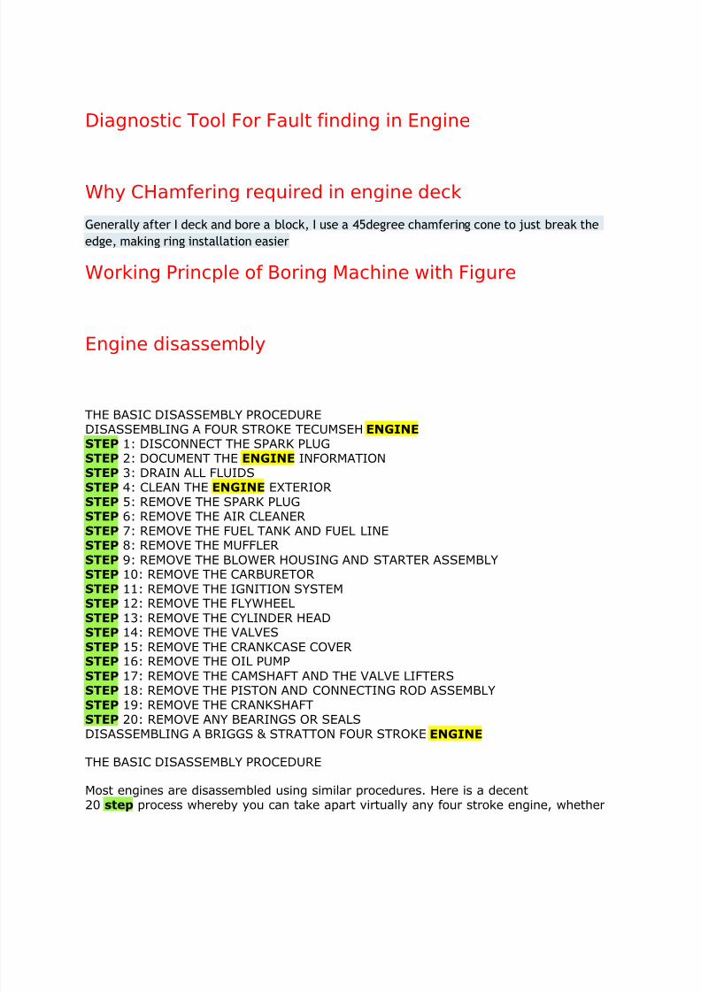
THE BASIC DISASSEMBLY PROCEDUREDISASSEMBLING A FOUR STROKE TECUMSEH ENGINE
STEP 1: DISCONNECT THE SPARK PLUGSTEP 2: DOCUMENT THE ENGINE INFORMATIONSTEP 3: DRAIN ALL FLUIDSSTEP 4: CLEAN THE ENGINE EXTERIORSTEP 5: REMOVE THE SPARK PLUG
STEP 6: REMOVE THE AIR CLEANERSTEP 7: REMOVE THE FUEL TANK AND FUEL LINESTEP 8: REMOVE THE MUFFLERSTEP 9: REMOVE THE BLOWER HOUSING AND STARTER ASSEMBLYSTEP 10: REMOVE THE CARBURETORSTEP 11: REMOVE THE IGNITION SYSTEMSTEP 12: REMOVE THE FLYWHEELSTEP 13: REMOVE THE CYLINDER HEADSTEP 14: REMOVE THE VALVESSTEP 15: REMOVE THE CRANKCASE COVERSTEP 16: REMOVE THE OIL PUMPSTEP 17: REMOVE THE CAMSHAFT AND THE VALVE LIFTERS
STEP 18: REMOVE THE PISTON AND CONNECTING ROD ASSEMBLYSTEP 19: REMOVE THE CRANKSHAFTSTEP 20: REMOVE ANY BEARINGS OR SEALSDISASSEMBLING A BRIGGS & STRATTON FOUR STROKE ENGINE
THE BASIC DISASSEMBLY PROCEDURE
Most engines are disassembled using similar procedures. Here is a decent20 step process whereby you can take apart virtually any four stroke engine, whether
7/28/2019 Learn Auto
http://slidepdf.com/reader/full/learn-auto 5/23
said engine is an old L head like the example we provide below, or an overheadvalve(OHV) or overhead cam(OHC) model. Because there are slight differencesbetween engines, it may be advantageous to juggle the order of some steps. Never beafraid to do so.
The biggest differences between an L head and an OHV motor is in the positioning of
the valves, making valve extraction a bit different. The camshaft will be positionedsimilarly in the crankcase in both these engines. The valves of an OHC engine will bepositioned like those of an OHV engine; however the camshaft will be located in thecylinder head rather than the crankcase, and its rotation by the crankshaft will be donevia a timing chain instead of intermeshed gears. While each of these engine configurations is unique in its way, none is significantly more complicatedto disassemble or work on than the others. Here is our 20 step disassembly procedure:
1)Disconnect spark plug wire and remove the engine from its equipment2)Document engine information3)Drain fluids from the engine
4)Thoroughly clean the engine exterior of dirt, grease, and debris
5)Remove the spark plug6)Remove the air cleaner7)Remove the fuel tank and disconnect the fuel line8)Remove the muffler9)Remove the blower housing and starter assembly10)Disconnect linkages and springs from the carburetor; remove the carburetor11)Remove the ignition coil or electronic ignition system12)Remove the flywheel13)Remove the cylinder head14)Remove the valves, valve springs, and valve spring retainers
15)Remove the crankcase cover16)Remove the oil pump
17)Remove the camshaft and valve lifters18)Disconnect the connecting rod from the crankshaft; remove the piston and
connecting rod assembly from the block19)Remove the crankshaft
20)Remove any bearings or seals in the crankcase
DISASSEMBLING A FOUR STROKE TECUMSEH ENGINE
Following are the above 20 steps applied to an 3.5 horsepower L head Tecumseh motorwith recoil start, a vertical crankshaft, and electronic ignition.
STEP 1: DISCONNECT THE SPARK PLUG
(Will be performed the same way on L head, OHV, OHC motors)
Before beginning work, disconnect the spark plug wire. Since most small engines runwith no outside power sources(like a battery), they can start unexpectedly as they arebeing worked on. To ensure that this does not happen, you should ground thedisconnected spark plug wire by fastening it to the engine block. On manyengines, agrounding stub will be located near the spark plug wire.
7/28/2019 Learn Auto
http://slidepdf.com/reader/full/learn-auto 6/23
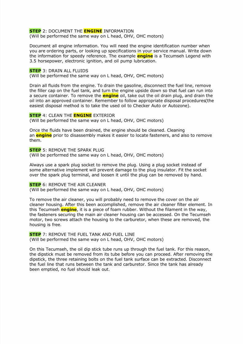
STEP 2: DOCUMENT THE ENGINE INFORMATION(Will be performed the same way on L head, OHV, OHC motors)
Document all engine information. You will need the engine identification number whenyou are ordering parts, or looking up specifications in your service manual. Write downthe information for speedy reference. The example engine is a Tecumseh Legend with
3.5 horsepower, electronic ignition, and oil pump lubrication.
STEP 3: DRAIN ALL FLUIDS(Will be performed the same way on L head, OHV, OHC motors)
Drain all fluids from the engine. To drain the gasoline, disconnect the fuel line, removethe filler cap on the fuel tank, and turn the engine upside down so that fuel can run intoa secure container. To remove the engine oil, take out the oil drain plug, and drain theoil into an approved container. Remember to follow appropriate disposal procedures(theeasiest disposal method is to take the used oil to Checker Auto or Autozone).
STEP 4: CLEAN THE ENGINE EXTERIOR
(Will be performed the same way on L head, OHV, OHC motors)
Once the fluids have been drained, the engine should be cleaned. Cleaning
an engine prior to disassembly makes it easier to locate fasteners, and also to removethem.
STEP 5: REMOVE THE SPARK PLUG(Will be performed the same way on L head, OHV, OHC motors)
Always use a spark plug socket to remove the plug. Using a plug socket instead of some alternative implement will prevent damage to the plug insulator. Fit the socketover the spark plug terminal, and loosen it until the plug can be removed by hand.
STEP 6: REMOVE THE AIR CLEANER(Will be performed the same way on L head, OHV, OHC motors)
To remove the air cleaner, you will probably need to remove the cover on the aircleaner housing. After this been accomplished, remove the air cleaner filter element. Inthis Tecumseh engine, it is a piece of foam rubber. Without the filament in the way,
the fasteners securing the main air cleaner housing can be accessed. On the Tecumsehmotor, two screws attach the housing to the carburetor, when these are removed, the
housing is free.
STEP 7: REMOVE THE FUEL TANK AND FUEL LINE
(Will be performed the same way on L head, OHV, OHC motors)
On this Tecumseh, the oil dip stick tube runs up through the fuel tank. For this reason,the dipstick must be removed from its tube before you can proceed. After removing thedipstick, the three retaining bolts on the fuel tank surface can be extracted. Disconnectthe fuel line that runs between the tank and carburetor. Since the tank has alreadybeen emptied, no fuel should leak out.
7/28/2019 Learn Auto
http://slidepdf.com/reader/full/learn-auto 7/23
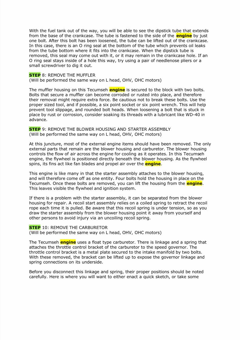
With the fuel tank out of the way, you will be able to see the dipstick tube that extendsfrom the base of the crankcase. The tube is fastened to the side of the engine by justone bolt. After this bolt has been loosened, the tube can be lifted out of the crankcase.In this case, there is an O ring seal at the bottom of the tube which prevents oil leaksfrom the tube bottom where it fits into the crankcase. When the dipstick tube isremoved, this seal may come out with it, or it may remain in the crankcase hole. If an
O ring seal stays inside of a hole this way, try using a pair of needlenose pliers or asmall screwdriver to dig it out.
STEP 8: REMOVE THE MUFFLER(Will be performed the same way on L head, OHV, OHC motors)
The muffler housing on this Tecumseh engine is secured to the block with two bolts.Bolts that secure a muffler can become corroded or rusted into place, and thereforetheir removal might require extra force. Be cautious not to break these bolts. Use theproper sized tool, and if possible, a six point socket or six point wrench. This will helpprevent tool slippage, and rounded bolt heads. When loosening a bolt that is stuck inplace by rust or corrosion, consider soaking its threads with a lubricant like WD-40 in
advance.
STEP 9: REMOVE THE BLOWER HOUSING AND STARTER ASSEMBLY
(Will be performed the same way on L head, OHV, OHC motors)
At this juncture, most of the external engine items should have been removed. The onlyexternal parts that remain are the blower housing and carburetor. The blower housingcontrols the flow of air across the engine for cooling as it operates. In this Tecumsehengine, the flywheel is positioned directly beneath the blower housing. As the flywheelspins, its fins act like fan blades and propel air over the engine.
This engine is like many in that the starter assembly attaches to the blower housing,
and will therefore come off as one entity. Four bolts hold the housing in place on theTecumseh. Once these bolts are removed, you can lift the housing from the engine.This leaves visible the flywheel and ignition system.
If there is a problem with the starter assembly, it can be separated from the blowerhousing for repair. A recoil start assembly relies on a coiled spring to retract the recoilrope each time it is pulled. Be aware that this recoil spring is under tension, so as youdraw the starter assembly from the blower housing point it away from yourself andother persons to avoid injury via an uncoiling recoil spring.
STEP 10: REMOVE THE CARBURETOR
(Will be performed the same way on L head, OHV, OHC motors)
The Tecumseh engine uses a float type carburetor. There is linkage and a spring thatattaches the throttle control bracket of the carburetor to the speed governor. Thethrottle control bracket is a metal plate secured to the intake manifold by two bolts.With these removed, the bracket can be lifted up to expose the governor linkage andspring connections on its underside.
Before you disconnect this linkage and spring, their proper positions should be notedcarefully. Here is where you will want to either enact a quick sketch, or take some
7/28/2019 Learn Auto
http://slidepdf.com/reader/full/learn-auto 8/23
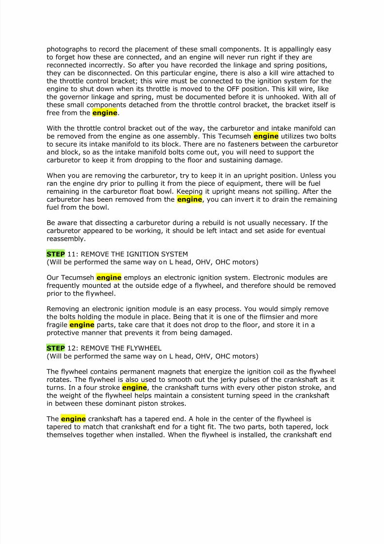
photographs to record the placement of these small components. It is appallingly easyto forget how these are connected, and an engine will never run right if they arereconnected incorrectly. So after you have recorded the linkage and spring positions,they can be disconnected. On this particular engine, there is also a kill wire attached tothe throttle control bracket; this wire must be connected to the ignition system for theengine to shut down when its throttle is moved to the OFF position. This kill wire, like
the governor linkage and spring, must be documented before it is unhooked. With all of these small components detached from the throttle control bracket, the bracket itself is
free from the engine.
With the throttle control bracket out of the way, the carburetor and intake manifold canbe removed from the engine as one assembly. This Tecumseh engine utilizes two boltsto secure its intake manifold to its block. There are no fasteners between the carburetorand block, so as the intake manifold bolts come out, you will need to support thecarburetor to keep it from dropping to the floor and sustaining damage.
When you are removing the carburetor, try to keep it in an upright position. Unless youran the engine dry prior to pulling it from the piece of equipment, there will be fuel
remaining in the carburetor float bowl. Keeping it upright means not spilling. After thecarburetor has been removed from the engine, you can invert it to drain the remainingfuel from the bowl.
Be aware that dissecting a carburetor during a rebuild is not usually necessary. If thecarburetor appeared to be working, it should be left intact and set aside for eventualreassembly.
STEP 11: REMOVE THE IGNITION SYSTEM(Will be performed the same way on L head, OHV, OHC motors)
Our Tecumseh engine employs an electronic ignition system. Electronic modules are
frequently mounted at the outside edge of a flywheel, and therefore should be removedprior to the flywheel.
Removing an electronic ignition module is an easy process. You would simply removethe bolts holding the module in place. Being that it is one of the flimsier and morefragile engine parts, take care that it does not drop to the floor, and store it in aprotective manner that prevents it from being damaged.
STEP 12: REMOVE THE FLYWHEEL
(Will be performed the same way on L head, OHV, OHC motors)
The flywheel contains permanent magnets that energize the ignition coil as the flywheel
rotates. The flywheel is also used to smooth out the jerky pulses of the crankshaft as itturns. In a four stroke engine, the crankshaft turns with every other piston stroke, andthe weight of the flywheel helps maintain a consistent turning speed in the crankshaftin between these dominant piston strokes.
The engine crankshaft has a tapered end. A hole in the center of the flywheel istapered to match that crankshaft end for a tight fit. The two parts, both tapered, lockthemselves together when installed. When the flywheel is installed, the crankshaft end
7/28/2019 Learn Auto
http://slidepdf.com/reader/full/learn-auto 9/23
will protrude through it, and a retaining nut attached to keep the two componentstightly bound.
A metal key is used to keep the flywheel from rotating on the end of the crankshaft.This flywheel key is a tiny piece of metal that fits into slots in the flywheel andcrankshaft end. When the flywheel is being detached from the crankshaft, watch for
this key; it is very small, and easily misplaced. Often(but not always) the flywheel keywill remain stuck to either the crankshaft or flywheel when these components areseparated. Always be sure that, after the flywheel is free, you locate the key, remove itfrom its slot, and store it in a good safe place.
Now consider how to best get the flywheel off of the crankshaft. First you must loosenthe flywheel retaining nut. Since the flywheel turns with the crankshaft, the flywheelcrankshaft assembly will also turn when you try to loosen the retaining nut. To preventthe flywheel from turning, you will need to use a tool called a flywheel holder. There aredifferent types of flywheel holders available: one kind uses a strap to harness theoutside edge of the flywheel and keep it from rotating; another slides between flywheelfins to prohibit rotation. An service manual will often specify what style flywheel holder
to use with a given engine. You may be able to obtain one designed for that enginefrom the manufacturer. When the flywheel holder is in place, you can remove theflywheel retaining nut and its washer; this Tecumseh engine also possesses a startercup which can now be withdrawn.
Even with the retaining nut removed, you will discover that the flywheel cannot simplybe pulled from the crankshaft. These two components wedge together so tightly thatanother special tool is needed to separate them. The tool in question will be either aknock off tool or a flywheel puller. As with the flywheel holder, the type of tool required,knock off or flywheel puller, will vary depending on the engine make and model. On ourTecumseh engine, a knock off tool is used. The knock off tool is a threaded piece of aluminum that can be screwed onto the threads of the crankshaft end. Then, to knock
the flywheel loose, you would pry up on it from underneath, and when it was loose,drive the crankshaft through it with a hammer. The only purpose of the knock off tool inthis case is to protect the end of the crankshaft from direct hammer blows; hammerblows could cause damage to the crankshaft end threads, or mushrooming of the metalcrankshaft tip. Either outcome would prevent reinstallation of the flywheel retaining nutlater. The aluminum knock off tool, when fitted over the threads, can be hammered onwith impunity to thread or crankshaft end damage.
The knock off tool should be threaded just partway onto the crankshaft. If it were to bescrewed on too tightly, it would prohibit the flywheel from coming off. With the tool inplace, pry up on the flywheel edge from underneath with a pry bar, as the flywheel isloosened by hammer strikes to the end of the puller. Usually one or two blows from a
hammer will dislodge the flywheel.
Remember to account for the flywheel key as soon as the flywheel is removed. Place it
where it will be protected and not lost.
STEP 13: REMOVE THE CYLINDER HEAD
L Head
7/28/2019 Learn Auto
http://slidepdf.com/reader/full/learn-auto 10/23
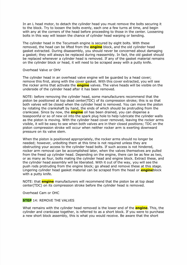
In an L head motor, to detach the cylinder head you must remove the bolts securing itto the block. Try to loosen the bolts evenly, each one a few turns at time, and beginwith any at the corners of the head before proceeding to those in the center. Looseningbolts in this way will lessen the chance of cylinder head warping or bending.
The cylinder head in the Tecumseh engine is secured by eight bolts. With these
removed, the head can be lifted from the engine block, and the old cylinder headgasket extracted. During disassembly, you should never be concerned about damaginga gasket; they will always be replaced during reassembly. In fact, the old gasket shouldbe replaced whenever a cylinder head is removed. If any of the gasket material remainson the cylinder block or head, it will need to be scraped away with a putty knife.
Overhead Valve or OHV
The cylinder head in an overhead valve engine will be guarded by a head cover;remove this first, along with the cover gasket. With this cover extracted, you will seethe rocker arms that activate the engine valves. The valve heads will be visible on the
underside of the cylinder head after it has been removed.
NOTE: before removing the cylinder head, some manufacturers recommend that thepiston be positioned at top dead center(TDC) of its compression stroke; this is so thatboth valves will be closed when the cylinder head is removed. You can move the pistonby rotating the crankshaft by hand, the ends of which should be protruding from thecrankcase. Since by now, the engine oil has been drained, you can dispense ateaspoonful or so of new oil into the spark plug hole to help lubricate the cylinder wallsas the piston is moving. With the cylinder head cover removed, leaving the rocker armsvisible, it will be easy to see when both valves are in their closed positions; TDC on thepiston compression stroke will occur when neither rocker arm is exerting downward
pressure on its valve stem.
When the piston is positioned appropriately, the rocker arms should no longer beneeded; however, unbolting them at this time is not required unless they areobstructing your access to the cylinder head bolts. If such access is not hindered,rocker arm removal can be accomplished later, when the valves themselves are pulledfrom the freed up cylinder head. Depending on the engine, there can be as few as two,or as many as four, bolts mating the cylinder head and engine block. Extract these, andthe cylinder head assembly will be liberated. With it out of the way, you will see thepush rods protruding from the engine block; go ahead and remove these at this stage.Lingering cylinder head gasket material can be scraped from the head or engineblock
with a putty knife.
NOTE: that engine manufacturers will recommend that the piston be at top dead
center(TDC) on its compression stroke before the cylinder head is removed.
Overhead Cam or OHC
STEP 14: REMOVE THE VALVES
What remains with the cylinder head removed is the lower end of the engine. This, thecylinder and crankcase together, is referred to as a short block. If you were to purchasea new short block assembly, this is what you would receive. Be aware that the short
7/28/2019 Learn Auto
http://slidepdf.com/reader/full/learn-auto 11/23
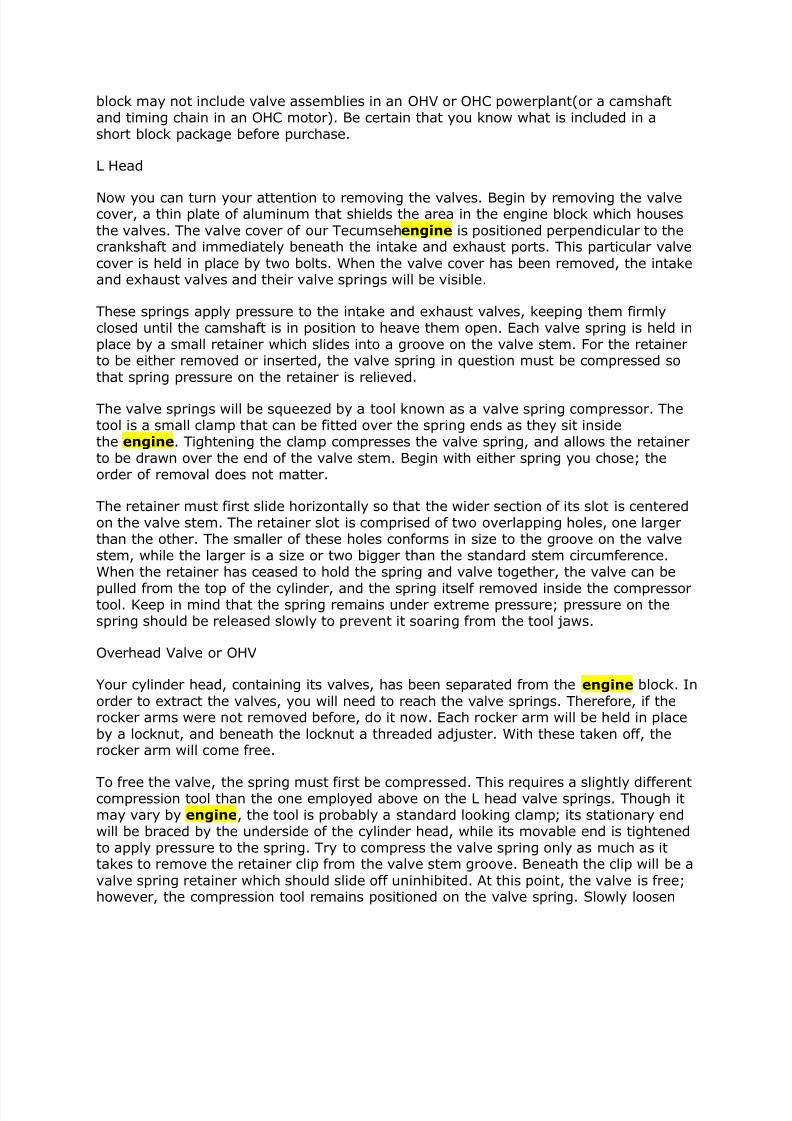
block may not include valve assemblies in an OHV or OHC powerplant(or a camshaftand timing chain in an OHC motor). Be certain that you know what is included in ashort block package before purchase.
L Head
Now you can turn your attention to removing the valves. Begin by removing the valvecover, a thin plate of aluminum that shields the area in the engine block which houses
the valves. The valve cover of our Tecumsehengine is positioned perpendicular to thecrankshaft and immediately beneath the intake and exhaust ports. This particular valve
cover is held in place by two bolts. When the valve cover has been removed, the intakeand exhaust valves and their valve springs will be visible.
These springs apply pressure to the intake and exhaust valves, keeping them firmlyclosed until the camshaft is in position to heave them open. Each valve spring is held inplace by a small retainer which slides into a groove on the valve stem. For the retainerto be either removed or inserted, the valve spring in question must be compressed so
that spring pressure on the retainer is relieved.
The valve springs will be squeezed by a tool known as a valve spring compressor. Thetool is a small clamp that can be fitted over the spring ends as they sit insidethe engine. Tightening the clamp compresses the valve spring, and allows the retainerto be drawn over the end of the valve stem. Begin with either spring you chose; theorder of removal does not matter.
The retainer must first slide horizontally so that the wider section of its slot is centeredon the valve stem. The retainer slot is comprised of two overlapping holes, one largerthan the other. The smaller of these holes conforms in size to the groove on the valvestem, while the larger is a size or two bigger than the standard stem circumference.When the retainer has ceased to hold the spring and valve together, the valve can be
pulled from the top of the cylinder, and the spring itself removed inside the compressortool. Keep in mind that the spring remains under extreme pressure; pressure on thespring should be released slowly to prevent it soaring from the tool jaws.
Overhead Valve or OHV
Your cylinder head, containing its valves, has been separated from the engine block. In
order to extract the valves, you will need to reach the valve springs. Therefore, if therocker arms were not removed before, do it now. Each rocker arm will be held in place
by a locknut, and beneath the locknut a threaded adjuster. With these taken off, therocker arm will come free.
To free the valve, the spring must first be compressed. This requires a slightly differentcompression tool than the one employed above on the L head valve springs. Though itmay vary by engine, the tool is probably a standard looking clamp; its stationary endwill be braced by the underside of the cylinder head, while its movable end is tightenedto apply pressure to the spring. Try to compress the valve spring only as much as ittakes to remove the retainer clip from the valve stem groove. Beneath the clip will be a
valve spring retainer which should slide off uninhibited. At this point, the valve is free;however, the compression tool remains positioned on the valve spring. Slowly loosen
7/28/2019 Learn Auto
http://slidepdf.com/reader/full/learn-auto 12/23
the valve spring compressor until it has released its pressure on the spring. By relievingthe pressure slowly, you can avoid the spring escaping and possibly injuring somebody.
Overhead Cam or OHC
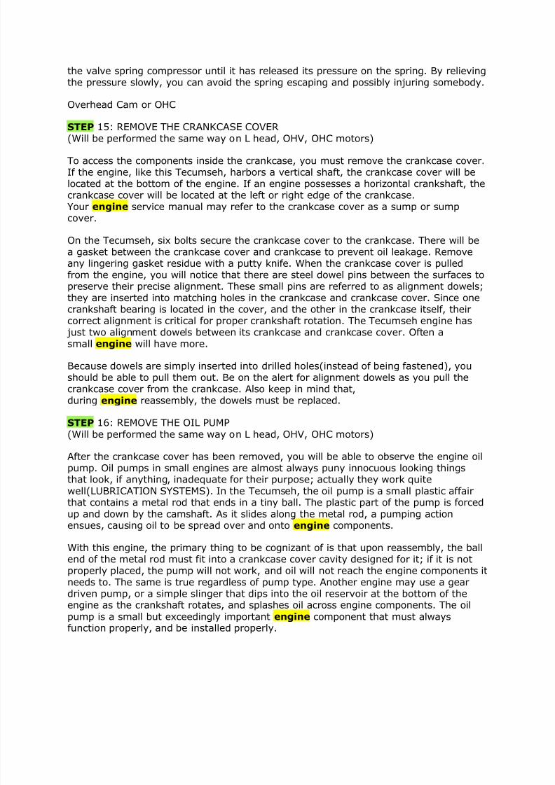
STEP 15: REMOVE THE CRANKCASE COVER
(Will be performed the same way on L head, OHV, OHC motors)
To access the components inside the crankcase, you must remove the crankcase cover.If the engine, like this Tecumseh, harbors a vertical shaft, the crankcase cover will belocated at the bottom of the engine. If an engine possesses a horizontal crankshaft, thecrankcase cover will be located at the left or right edge of the crankcase.Your engine service manual may refer to the crankcase cover as a sump or sumpcover.
On the Tecumseh, six bolts secure the crankcase cover to the crankcase. There will bea gasket between the crankcase cover and crankcase to prevent oil leakage. Removeany lingering gasket residue with a putty knife. When the crankcase cover is pulled
from the engine, you will notice that there are steel dowel pins between the surfaces topreserve their precise alignment. These small pins are referred to as alignment dowels;they are inserted into matching holes in the crankcase and crankcase cover. Since onecrankshaft bearing is located in the cover, and the other in the crankcase itself, theircorrect alignment is critical for proper crankshaft rotation. The Tecumseh engine has just two alignment dowels between its crankcase and crankcase cover. Often asmall engine will have more.
Because dowels are simply inserted into drilled holes(instead of being fastened), youshould be able to pull them out. Be on the alert for alignment dowels as you pull thecrankcase cover from the crankcase. Also keep in mind that,during engine reassembly, the dowels must be replaced.
STEP 16: REMOVE THE OIL PUMP
(Will be performed the same way on L head, OHV, OHC motors)
After the crankcase cover has been removed, you will be able to observe the engine oilpump. Oil pumps in small engines are almost always puny innocuous looking thingsthat look, if anything, inadequate for their purpose; actually they work quite
well(LUBRICATION SYSTEMS). In the Tecumseh, the oil pump is a small plastic affairthat contains a metal rod that ends in a tiny ball. The plastic part of the pump is forced
up and down by the camshaft. As it slides along the metal rod, a pumping actionensues, causing oil to be spread over and onto engine components.
With this engine, the primary thing to be cognizant of is that upon reassembly, the ballend of the metal rod must fit into a crankcase cover cavity designed for it; if it is notproperly placed, the pump will not work, and oil will not reach the engine components itneeds to. The same is true regardless of pump type. Another engine may use a geardriven pump, or a simple slinger that dips into the oil reservoir at the bottom of theengine as the crankshaft rotates, and splashes oil across engine components. The oil
pump is a small but exceedingly important engine component that must alwaysfunction properly, and be installed properly.
7/28/2019 Learn Auto
http://slidepdf.com/reader/full/learn-auto 13/23
To remove the Tecumseh oil pump, you would just slide it off of the camshaft. It maybe desirable to first pull the metal rod from the pump to prevent damage. If an enginecontains a mechanical speed governor, like this Tecumseh, it will likely be visible on theinside surface of the crankcase cover. A mechanical governor operates on the basis of centrifugal force. It will contain a gear whose teeth mesh with the teeth of either acamshaft or crankshaft gear. As engine speed increases, the cam or crankshaft gear
spins the governor gear at an accelerated pace; this causes a pair of weights attachedto the governor gear to swing outward, drawing a governor plate against a lever that,
through a system or springs and linkage, influences engine speed at the carburetor.
This particular engine is similar to many in that its governor cannot be removed orinstalled easily. As long as the governor functioned effectively before the engine wasdisassembled, and if it appears to be in good condition after a careful visualexamination, then it should not be removed.
STEP 17: REMOVE THE CAMSHAFT AND THE VALVE LIFTERS
L Head and Overhead Valve or OHV
If you are working on one of these engines, you will be able to see a pair of intermeshing gears inside the crankcase with the crankcase cover removed. A gear onthe crankshaft is mated to larger gear on the camshaft. The camshafts in L head andOHV engines will be positioned similarly in the crankcase.
Both the crankshaft and camshaft gears will be endowed with punch marks which needto be aligned when the engine is reassembled to ensure that the valves open and closeat proper intervals. To remove the camshaft in an L head engine, the timing marks onthe gears should be aligned(should not be necessary in an OHV powerplant). Rotate theL head camshaft until the punch marks line up. This guarantees that there will be noload on the cam as it is removed. With the valves previously extracted, load on the
camshaft will be minimized, however it still makes sense to have the marks aligned.Most of the time, timing marks on the intermeshing crankshaft and camshaft gears aredesigned to line up when the piston reaches top dead center or TDC onthe engine compression stroke. At this point, the cam lobes will not be activating thevalve lifters, making it that much easier to remove the cam from the crankcase.
With the camshaft withdrawn, you will perceive above where it was positioned twometal rods with wide flat ends; they will be stretching downward from the top of theengine block. These are the valve lifters or tappets. The wide flat end surface of thevalve lifter is what contacts the camshaft lobe. In an L head motor, the opposing end of the lifter will press against the valve stem; in an OHV engine, it will press against apushrod which, in turn, pushes on a rocker arm to open the valve. In either engine
configuration, the valve lifter will stimulate an opening of the valve whenever theoblong side of the cam lobe rotates against it. There will be two lifters in a singlecylinder L head or OHV engine, one for each valve; with the camshaft removed, theyshould be easy to pull out.
Overhead Cam of OHC
STEP 18: REMOVE THE PISTON AND CONNECTING ROD ASSEMBLY
(Will be performed the same way on L head, OHV, OHC motors)
7/28/2019 Learn Auto
http://slidepdf.com/reader/full/learn-auto 14/23
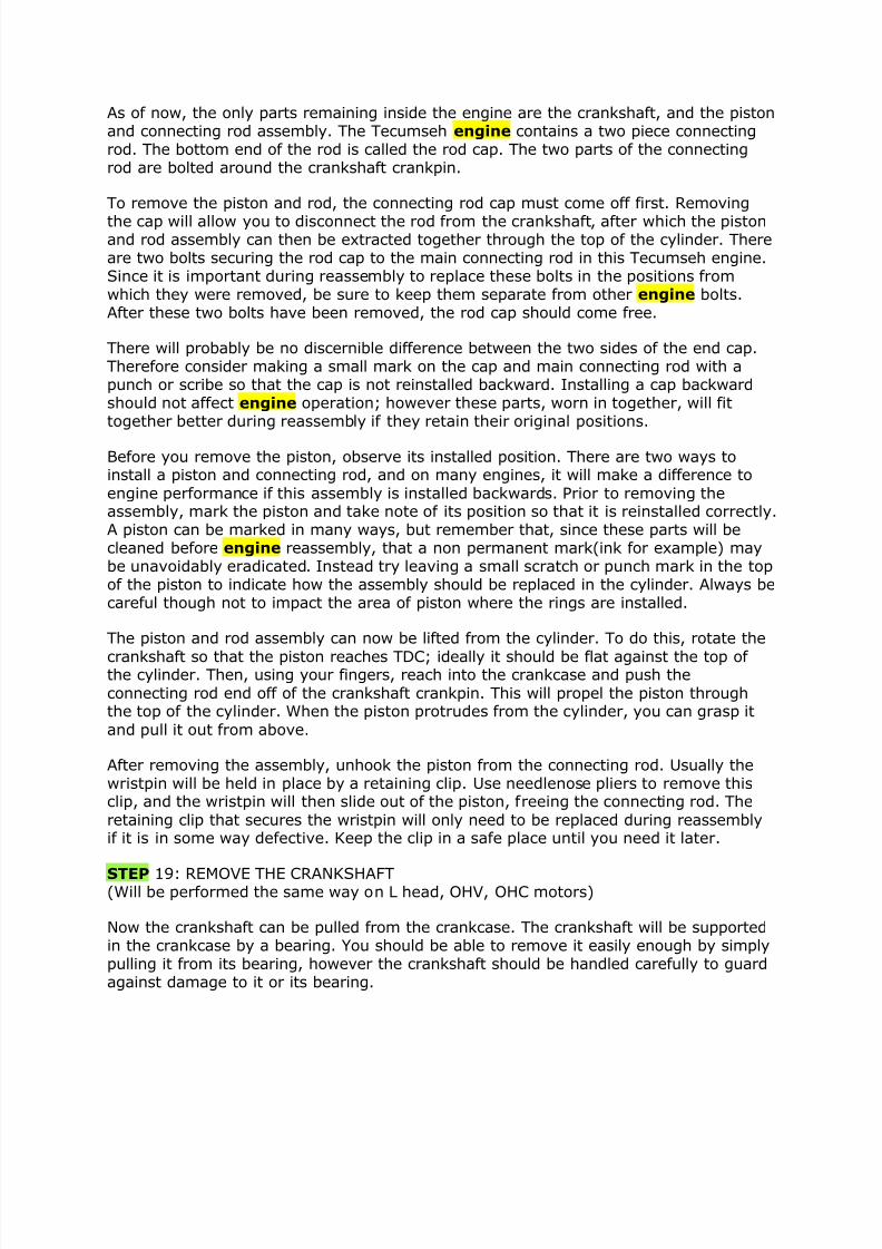
As of now, the only parts remaining inside the engine are the crankshaft, and the pistonand connecting rod assembly. The Tecumseh engine contains a two piece connectingrod. The bottom end of the rod is called the rod cap. The two parts of the connectingrod are bolted around the crankshaft crankpin.
To remove the piston and rod, the connecting rod cap must come off first. Removing
the cap will allow you to disconnect the rod from the crankshaft, after which the pistonand rod assembly can then be extracted together through the top of the cylinder. Thereare two bolts securing the rod cap to the main connecting rod in this Tecumseh engine.Since it is important during reassembly to replace these bolts in the positions fromwhich they were removed, be sure to keep them separate from other engine bolts.After these two bolts have been removed, the rod cap should come free.
There will probably be no discernible difference between the two sides of the end cap.Therefore consider making a small mark on the cap and main connecting rod with apunch or scribe so that the cap is not reinstalled backward. Installing a cap backwardshould not affect engine operation; however these parts, worn in together, will fittogether better during reassembly if they retain their original positions.
Before you remove the piston, observe its installed position. There are two ways toinstall a piston and connecting rod, and on many engines, it will make a difference to
engine performance if this assembly is installed backwards. Prior to removing theassembly, mark the piston and take note of its position so that it is reinstalled correctly.A piston can be marked in many ways, but remember that, since these parts will becleaned before engine reassembly, that a non permanent mark(ink for example) maybe unavoidably eradicated. Instead try leaving a small scratch or punch mark in the topof the piston to indicate how the assembly should be replaced in the cylinder. Always becareful though not to impact the area of piston where the rings are installed.
The piston and rod assembly can now be lifted from the cylinder. To do this, rotate the
crankshaft so that the piston reaches TDC; ideally it should be flat against the top of the cylinder. Then, using your fingers, reach into the crankcase and push the
connecting rod end off of the crankshaft crankpin. This will propel the piston throughthe top of the cylinder. When the piston protrudes from the cylinder, you can grasp it
and pull it out from above.
After removing the assembly, unhook the piston from the connecting rod. Usually thewristpin will be held in place by a retaining clip. Use needlenose pliers to remove thisclip, and the wristpin will then slide out of the piston, freeing the connecting rod. The
retaining clip that secures the wristpin will only need to be replaced during reassemblyif it is in some way defective. Keep the clip in a safe place until you need it later.
STEP 19: REMOVE THE CRANKSHAFT(Will be performed the same way on L head, OHV, OHC motors)
Now the crankshaft can be pulled from the crankcase. The crankshaft will be supportedin the crankcase by a bearing. You should be able to remove it easily enough by simplypulling it from its bearing, however the crankshaft should be handled carefully to guardagainst damage to it or its bearing.
7/28/2019 Learn Auto
http://slidepdf.com/reader/full/learn-auto 15/23
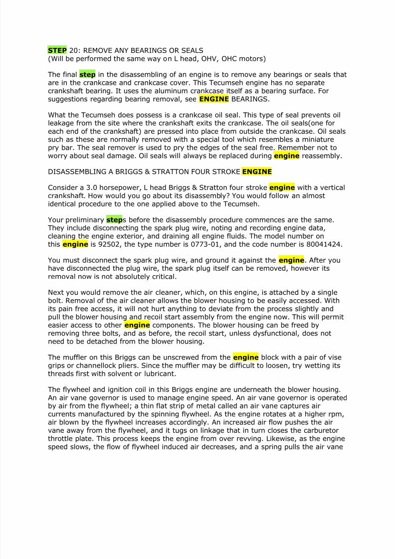
STEP 20: REMOVE ANY BEARINGS OR SEALS(Will be performed the same way on L head, OHV, OHC motors)
The final step in the disassembling of an engine is to remove any bearings or seals thatare in the crankcase and crankcase cover. This Tecumseh engine has no separatecrankshaft bearing. It uses the aluminum crankcase itself as a bearing surface. For
suggestions regarding bearing removal, see ENGINE BEARINGS.
What the Tecumseh does possess is a crankcase oil seal. This type of seal prevents oilleakage from the site where the crankshaft exits the crankcase. The oil seals(one for
each end of the crankshaft) are pressed into place from outside the crankcase. Oil sealssuch as these are normally removed with a special tool which resembles a miniaturepry bar. The seal remover is used to pry the edges of the seal free. Remember not toworry about seal damage. Oil seals will always be replaced during engine reassembly.
DISASSEMBLING A BRIGGS & STRATTON FOUR STROKE ENGINE
Consider a 3.0 horsepower, L head Briggs & Stratton four stroke engine with a vertical
crankshaft. How would you go about its disassembly? You would follow an almostidentical procedure to the one applied above to the Tecumseh.
Your preliminary steps before the disassembly procedure commences are the same.They include disconnecting the spark plug wire, noting and recording engine data,cleaning the engine exterior, and draining all engine fluids. The model number onthis engine is 92502, the type number is 0773-01, and the code number is 80041424.
You must disconnect the spark plug wire, and ground it against the engine. After youhave disconnected the plug wire, the spark plug itself can be removed, however its
removal now is not absolutely critical.
Next you would remove the air cleaner, which, on this engine, is attached by a singlebolt. Removal of the air cleaner allows the blower housing to be easily accessed. Withits pain free access, it will not hurt anything to deviate from the process slightly andpull the blower housing and recoil start assembly from the engine now. This will permiteasier access to other engine components. The blower housing can be freed byremoving three bolts, and as before, the recoil start, unless dysfunctional, does notneed to be detached from the blower housing.
The muffler on this Briggs can be unscrewed from the engine block with a pair of visegrips or channellock pliers. Since the muffler may be difficult to loosen, try wetting itsthreads first with solvent or lubricant.
The flywheel and ignition coil in this Briggs engine are underneath the blower housing.An air vane governor is used to manage engine speed. An air vane governor is operatedby air from the flywheel; a thin flat strip of metal called an air vane captures aircurrents manufactured by the spinning flywheel. As the engine rotates at a higher rpm,air blown by the flywheel increases accordingly. An increased air flow pushes the airvane away from the flywheel, and it tugs on linkage that in turn closes the carburetorthrottle plate. This process keeps the engine from over revving. Likewise, as the enginespeed slows, the flow of flywheel induced air decreases, and a spring pulls the air vane
7/28/2019 Learn Auto
http://slidepdf.com/reader/full/learn-auto 16/23
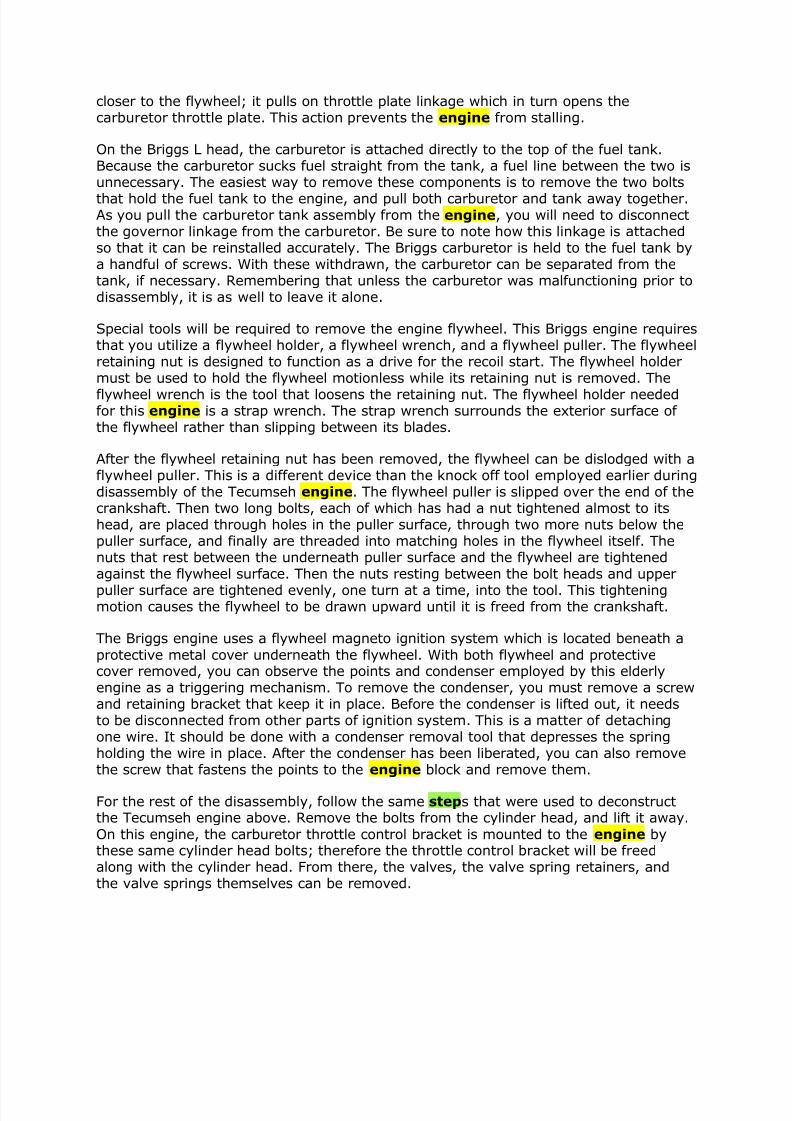
closer to the flywheel; it pulls on throttle plate linkage which in turn opens thecarburetor throttle plate. This action prevents the engine from stalling.
On the Briggs L head, the carburetor is attached directly to the top of the fuel tank.Because the carburetor sucks fuel straight from the tank, a fuel line between the two isunnecessary. The easiest way to remove these components is to remove the two bolts
that hold the fuel tank to the engine, and pull both carburetor and tank away together.As you pull the carburetor tank assembly from the engine, you will need to disconnectthe governor linkage from the carburetor. Be sure to note how this linkage is attachedso that it can be reinstalled accurately. The Briggs carburetor is held to the fuel tank bya handful of screws. With these withdrawn, the carburetor can be separated from thetank, if necessary. Remembering that unless the carburetor was malfunctioning prior todisassembly, it is as well to leave it alone.
Special tools will be required to remove the engine flywheel. This Briggs engine requiresthat you utilize a flywheel holder, a flywheel wrench, and a flywheel puller. The flywheelretaining nut is designed to function as a drive for the recoil start. The flywheel holdermust be used to hold the flywheel motionless while its retaining nut is removed. The
flywheel wrench is the tool that loosens the retaining nut. The flywheel holder neededfor this engine is a strap wrench. The strap wrench surrounds the exterior surface of the flywheel rather than slipping between its blades.
After the flywheel retaining nut has been removed, the flywheel can be dislodged with aflywheel puller. This is a different device than the knock off tool employed earlier duringdisassembly of the Tecumseh engine. The flywheel puller is slipped over the end of thecrankshaft. Then two long bolts, each of which has had a nut tightened almost to itshead, are placed through holes in the puller surface, through two more nuts below thepuller surface, and finally are threaded into matching holes in the flywheel itself. Thenuts that rest between the underneath puller surface and the flywheel are tightenedagainst the flywheel surface. Then the nuts resting between the bolt heads and upper
puller surface are tightened evenly, one turn at a time, into the tool. This tighteningmotion causes the flywheel to be drawn upward until it is freed from the crankshaft.
The Briggs engine uses a flywheel magneto ignition system which is located beneath a
protective metal cover underneath the flywheel. With both flywheel and protectivecover removed, you can observe the points and condenser employed by this elderlyengine as a triggering mechanism. To remove the condenser, you must remove a screwand retaining bracket that keep it in place. Before the condenser is lifted out, it needsto be disconnected from other parts of ignition system. This is a matter of detachingone wire. It should be done with a condenser removal tool that depresses the springholding the wire in place. After the condenser has been liberated, you can also removethe screw that fastens the points to the engine block and remove them.
For the rest of the disassembly, follow the same steps that were used to deconstructthe Tecumseh engine above. Remove the bolts from the cylinder head, and lift it away.
On this engine, the carburetor throttle control bracket is mounted to the engine bythese same cylinder head bolts; therefore the throttle control bracket will be freedalong with the cylinder head. From there, the valves, the valve spring retainers, andthe valve springs themselves can be removed.
7/28/2019 Learn Auto
http://slidepdf.com/reader/full/learn-auto 17/23
Next you would remove the crankcase cover to reveal the internal engine components.This Briggs motor has a different oil pump than the one used by the Tecumseh. It is atype of slinger(LUBRICATION SYSTEMS) that resides in oil at the bottom of thecrankcase, and is rotated via intermeshing gears by the camshaft. Paddles on the outeredge of the slinger dip into crankcase oil and fling it over engine parts, affording themlubrication as the engine runs. The faster the engine runs, the faster the slinger
rotates, and the more lubrication oil it flings.
The Briggs & Stratton engine contains a two piece connecting rod. If the rod cap isunbolted, the piston and main connecting rod can be removed, as with the Tecumseh,through the top of the cylinder. The crankshaft can then be pulled from the crankcase.This engine contains the same kind of crankshaft bearing as the Tecumseh; in otherwords, the aluminum crankcase itself serves as the crankshaft bearing. Therefore thereis no bearing to remove. Also like the Tecumseh, the Briggs engine does use oil seals.For hints regarding seal removal, visit the section on ENGINE BEARINGS
Crack Detection and Correction
Cracks don’t necessarily have to spell the end of an engine component’s life
By Doug Kaufman
First off, let’s get one thing perfectly clear – there’s no such thing as “flawless.” Like
those shocking tabloid photos of that Hollywood actress who gets blindsided beside abistro, even the most conscientious engine builder sometimes has to deal withsurprising surface imperfections.
And just as she has paparazzi to expose the damage and makeup artists to cover it up,today’s engine builders can call on a number of state-of-the-art tools and techniques tolocate, identify and remediate cracks and other damage in a variety of enginecomponents.
7/28/2019 Learn Auto
http://slidepdf.com/reader/full/learn-auto 18/23
Without excellent crack detection and repair methods, what you can’t see can mostdefinitely hurt you.
Crack Detection
Depending on their locations, crack severity will vary. They tend to form, spread and getworse as heat, thermal stress, heavy loads, repeated bending and flexing, metal fatigue,pounding and vibration take their toll on a part. Cracking is an indication that an area isexperiencing more stress than it can handle.
Finding those cracks will enable you to determine whether you should repair or replacethose parts. You simply can’t afford to spend a lot of time machining or reconditioningcores or used parts that may be destined for failure.
With hard-to-find and high value cores and parts, the decision may hinge on the extentof the damage. If the part can be repaired economically and with a high degree of
success, then it’s probably worth fixing. But if it can’t, you’ll have to factor in the cost toreplace it.
Never assume a part or a casting is okay just because you can’t see any visible cracks. Always assume there may be cracks – although, because engine parts are made of somany different materials these days, finding them may be a challenge.
Magnetic Particle InspectionMagnetic particle inspection is most often used to inspect cast iron or steel alloys thatare “ferromagnetic” and can be temporarily magnetized for such things as surfacecracks in and around the cylinder head combustion chambers and for inspecting
crankshafts, camshafts and connecting rods. But the technique can also be used tocheck gears, shafts, axles and steering and suspension components for cracks, too.
Magnetic particle inspection won’t work on nonferrous metals such as aluminum,magnesium, titanium, nonmagnetic alloys of stainless steel or plastic.
A magnetic field created in various ways causes tiny iron oxide particles that aresprayed or brushed on the part to reveal any cracks. If there are any cracks in thesurface of the part, they will disrupt the magnetic field and act like a pole to attract theiron particles.
The iron particles (sized between .125” and 60 microns), may be applied in a drypowder or a wet solution. They can be dyed yellow, white, red, gray, black or other fluorescent color to improve their visibility against the metal background. With thefluorescent particles, an ultraviolet black light is required to make the particles stand out.
The wet particle detection method is more sensitive than the dry method for finding verysmall cracks, but dry particles are better for finding cracks that may be just under thesurface (subsurface flaws).

7/28/2019 Learn Auto
http://slidepdf.com/reader/full/learn-auto 19/23
7/28/2019 Learn Auto
http://slidepdf.com/reader/full/learn-auto 20/23
It is often used in conjunction with these other methods of crack detection to check theintegrity of the cooling jackets in the cylinder head and block, to find leaks other techniques can’t (such as porosity leaks in aluminum castings) and to see if visiblecracks are really leaking or not.
Vacuum TestingVacuum testing is the same basic idea as pressure testing, except in reverse. Instead of using air pressure to test the cooling jackets for leaks, vacuum is used on a head or block after the water outlets have been plugged. If the casting holds vacuum, there areno leaks. But if it doesn’t, you’ve found a leaker.
Unfortunately, this technique does not use water or dye to pinpoint the leak so you stillhave to use one of the other techniques to find the leak. It’s mostly a quick check for verifying the integrity of a casting.
Ultrasonic Testing
More commonly used in industrial and aviation applications, ultrasonics can also beused to find internal flaws in castings and other parts. The technology uses soundwaves to find cracks. A transponder generates an acoustic signal (up to 25 MHz) thatpasses into and through the part. Cracks or flaws will reflect some of the sound wavesback to the detector, which allows the information to be displayed on the tester.
The best applications for ultrasonic testing include heavy castings, large shafts andexpensive parts that may be used for racing or extreme-duty service. Ultrasonics canalso be used to check the integrity of welds and welded castings. They can also beused to check for the integrity of cylinder wall thicknesses before or after boring.
You can find a lot more detail about each of these crack detection methods inour archived stories or in the September 2006 issue of Engine Builder magazine.
Crack Repair According to Engine Builder’s 2012 Machine Shop Market Profile (published in the Julyissue and available online), cylinder head work remains one of, if not the biggest part of many machine shops’ production. Though production numbers have shown somedeclines, cylinder heads continue to be profitable in gas and diesel rebuild facilities.
Yet despite our industry’s traditional ability to get the most out of its components, welearned that fewer cylinder heads are being repaired. We found that nearly 26 percentof diesel heads and nearly 30 percent of aluminum heads are being scrapped, bothnumbers significantly higher than last year. Obviously, part of this can be attributed tothe low cost alternatives available in the aftermarket. But in cases of value or scarcity,parts are repaired and many shops do the work themselves. How they do it depends onwhat it is.
Apparently, the mystery of aluminum welding is less frightening because an increasingnumber of respondents say they weld cracked aluminum cylinder heads. Welding is

7/28/2019 Learn Auto
http://slidepdf.com/reader/full/learn-auto 21/23
used nearly 83 percent of the time, up from 77 percent last year. For diesel heads,welding is performed 25 percent of the time. Pinning remains the most-often usedmethod for repairing cast iron cylinder heads, and has opened up a huge lead over welding.
“With later model heads, we find many cracks are caused by design issues,” says GaryReed, of Lock-N-Stitch. “These may be related to lighter castings, 3- and 4-valve headswith seats nearly touching each other and everything else from too few head bolts toinduction hardened valve seats in cast iron heads. Compared to engines manufactured30 or more years ago, the cracking rate is much higher now.
Reed classifies all cracked castings into two categories: those that cracked due to anaccident or incident like impact, freezing or overheating and those that cracked duringnormal operating conditions, which indicates a design issue or usage beyond the designcapabilities.
Within aluminum cylinder heads, Reed finds stripped sparkplug threads and other threaded bolt holes, cracks between valve seats and corrosion due to lack of coolantmaintenance are frequent complaints. With cast iron heads, he says induction hardenedseats will eventually result in cracks across the seats but cracks in the combustionchambers due to poor cooling caused by design or maintenance issues is still thebiggest problem.
Small diesel heads that frequently crack in areas with little or no coolant exposure havebecome common. Valve seat insert bores that are too close together often don’t haveenough strength to support the press fit of the seat inserts.
Most of the cracking issues with engine blocks are related to cylinder wall thickness…or to be more precise, thinness. “Core shift has always been an issue but in today’s blocksthe dramatic thinning of the walls often leads to strain cracks,” Reed says.
Other problems are seen with main and head bolt hole cracks due to the damagingradial forces exerted form the threads when torqued. Freezing still occurs but not asoften as earlier blocks. Light marine blocks always provide a great source of revenueand profit due to the increased value over automotive blocks of the same design.
“Diesels seem to crack more than gas engines mostly due to their life cycle,” Reedsays. “Also, more diesels are made from cast iron now while gas engines see a higher number of aluminum components. In diesel blocks, connecting rod failures are fairlycommon and remain some of the easiest and most lucrative to repair.”
Pinning is the most commonly used technique for repairing cracks in cast iron headsbecause it’s fast, reliable and cheap. It can also be used to repair aluminum castings,too. Pinning is a relatively easy technique to learn and use, doesn’t require any specialtools other than a drill, guide fixture and tap, and uses no heat.

7/28/2019 Learn Auto
http://slidepdf.com/reader/full/learn-auto 22/23
The technique involves drilling holes in both ends of the crack to keep it from spreading,then drilling holes at various intervals along the length of the crack, installingoverlapping pins to fill the crack, then peening over the pins with an air hammer to sealand blend the surface. Either tapered pins or straight pins may be used.
If a crack is along an outside edge or corner that requires support to hold the sides of the crack together, or if the crack is in an area that would open up or pull apart when thecasting is under load or gets hot, ordinary pins won’t work.
One solution is to use “locks” to hold the two sides of the crack together, and/or to usespecial pins that have a “spiral hook” or “reverse pitch” thread pattern. These pins canactually hold a crack together rather than just fill it.
Cracks in thin areas of a casting (thinner than 1/8˝) can be difficult to repair because themetal isn’t thick enough to support the threads on a standard pin. For theseapplications, very small pins must be used to fill the crack.
On some applications, the crack between the valve seats can often be repaired with asingle soft steel pin that has a countersunk shoulder. A steel pin works best in thisapplication because it can withstand heat better than a cast iron pin. After the crack hasbeen fixed, the seats can be remachined. There should be no need to cut the head toaccept valve seat inserts.
Welding is another exceptional method of repairing damaged components, says KarlHoes, instructor at Lincoln Electric’s Motorsports Welding School. Welding techniquesvary, but the basic idea is to melt the surrounding metal and fill the crack with moltenmetal and filler rod.
An experienced welder can even “recast” a badly damaged area, saving a head thatwould otherwise be junk. The strongest welds are achieved by using a filler rod that’sthe same alloy as the head, or very close to it.
Hoes says there are many ways to repair aluminum and cast iron components withwelding. While none of them are easy, exactly, experience and skill can allow you torepair many parts you might have trashed before.
“With aluminum cylinder heads, for example, TIG welding is commonly used. But headsare a really thick mass, and can be hard to weld on. Typically, we would weld aluminumon AC, alternating current. What we’ve been seeing is guys going to DC on aluminumheads,” explains Hoes. “They use straight helium gas, which allows them to get the heatinto it very quickly. The helium adds a lot of heat to the arc.”
Aluminum is a superhighway for heat, says Hoes, conducting heat rapidly away duringthe welding process. “To get the aluminum to melt, you’ve got to get it up to 1,200degrees F. You may have a 10,000 degree F arc but that huge chunk of aluminum ispulling it away as fast as you’re putting it in. And it’s expensive to use helium instead of

7/28/2019 Learn Auto
http://slidepdf.com/reader/full/learn-auto 23/23
argon to TIG weld. But sometimes you have to add helium to the gas just to get moreheat into the work faster.”
Hoes points out that size does matter, especially when it comes to welding equipment.“These guys are using large machines. A lot of hobbyists have TIG machines at home –
but they don’t have the equipment needed to do this kind of work. It’s definitely nothobby equipment for a professional engine shop. You just won’t get good results. Youmay be able to fool yourself into thinking you’re doing the work, but you won’t fool themetal.”
It is true for aluminum, that you have to have advanced welding skills. You have to knowhow to TIG or MIG weld to repair aluminum blocks. For cast iron, you have tounderstand a little bit about metallurgy. There’s more involved than just running a nicebead. It’s understanding what happens to that steel when you weld on it, that you’relikely going to harden it up and make it brittle.
You need to remember that filler material makes a huge difference, says Hoes.Depending on the materials you’re trying to weld, their application, the desired sheer strength or ductility and many other factors, filler materials will be very different case-to-case.
“But while welding does take a certain skill set, as far as it being a profit center, yeah, itis,” says Hoes. “Because when it takes more skill or special equipment to do something,there’s not as many people willing to do it.”


![Automatic Machine Learning (AutoML): A Tutorial · –Based on scikit-learn & TPE Auto-sklearn [Feurer al, NIPS 2015] –Based on scikit-learn & SMAC / BOHB –Uses meta-learning](https://img.pdfslide.net/doc/110x75/5ec5f00238130663f40e65bf/automatic-machine-learning-automl-a-tutorial-abased-on-scikit-learn-tpe.jpg)