Embed Size (px)
Citation preview

Learning Lane Change Trajectories From On-road Driving Data
Wen Yao, Huijing Zhao, Franck Davoine, Hongbin Zha
Abstract— Lane change is one of the most principle drivingbehaviors on structure roads. It frequently happens in dailydriving. A key issue in lane change technique is trajectoryplanning, where a set of trajectories describing possible vehiclemotions are generated by applying a parametric function, andby uniformly sampling the end states in configuration space;the trajectories are then examined to find an optimal one forexecution. However, such a trajectory set has poor efficiency dueto the large sample number. Many trajectories in this set seldomhappen in real human driving behaviors. In this research, lanechange trajectories are collected from real driving data ofdifferent drivers. Their statistics are analyzed, through which, asimplified trajectory set is generated. Experiment results showthat the trajectory set has much less number of samples but canstill guarantee to cover usual lane change behaviors of humanbeing.
I. INTRODUCTION
A. Motivation
An advanced intelligent vehicle is usually equipped withthree modules: perception, decision and execution .Percep-tion module finds the host vehicle’s pose (i.e. location andorientation), and monitors road and other traffic participantsat its local surroundings using sensors such as GPS/IMU,camera, LiDAR, radar and so on. Based on such information,decision module aware driving situation through risk assess-ment, prediction etc., makes a ”good” decision for maneuver.Execution module converts the decision to either messagesfor driving assistant or control commands for autonomousdriving. In this research, we focus on the trajectory planningfor lane change behavior, which is a key issue in decisionmodule.
Lane keeping (or car following) and lane change are twoprincipal driving behaviors on structure roads, which happenfrequently in daily driving. Comparing with lane keeping orcar following, which is well studied [1][2] with many ma-ture techniques being applied in commercial products, lanechange is more complicated. A key issue in lane change tech-nique is trajectory planning. A trajectory is planned, whichsatisfies the host vehicle’s non-holonomic constrains, andthen optimized considering the indices such as safety, timeand comfort, and more importantly, is in line with humandriving behaviors. There have been many researches on lanechange trajectory planning [3][4][5], a classic frameworkcontains the following steps: 1) sampling the host vehicle’s
This work is partially supported by the NSFC-ANR Grants(No.61161130528), and the NSFC Grants (No.60975061, No.90920304).
W. Yao, H. Zhao, and H. Zha are with the State Key Labof Machine Perception (MOE), Peking University, Beijing [email protected]
F. Davoine is with CNRS, LIAMA Sino French Laboratory, Beijing,China.
future states (e.g. in 2 seconds) and constructing a set ofend state candidates; 2) a set of trajectories (trajectory set)that describing possible vehicle motion paths are generatedby applying a parametric function to an initial state witheach end state candidate; 3) examining the trajectories tofind an optimal one for execution, according to an objectivefunction on the indices such as safety, time and comfort.A key issue here is how to sample the candidate states sothat it can cover various cases in daily lane change behavior.A common solution is to sample the configuration space offuture states using uniform lattice. Though all the trajectoriesin the uniformly sampled space are guaranteed to be feasiblefor vehicle’s maneuver, many of them are seldom used byhuman being in real driving situation. These trajectories risecomputation cost and degrade efficiency of the planner.
Inspired by human lane change behaviors, this workpropose a method to simplify the above traditional trajectoryset through learning from the real driving data of differentdrivers, where a trajectory set that representing the usual lanechange behaviors is generated, so that online computationcan be conducted with more focus and efficiency. Thisresearch is described as a function in the driving behaviorlearning module, which is an offline procedure to generatemodels for online inference and planning.
B. Related Work
From the 2007 DARPA Urban Chanllenge competition forintelligent vehicles in simplified urban scenarios, to the on-road driving experiment of Google driveless vehicle, drivingbehavior research in urban scenario becomes more and moreactive. Lane change behavior is one of the most importantpart of daily urban driving. There are a lot of researchwork on this topic. Authors of [3] constructs a roadmapfor highway lane change in traffic simulation application.Authors in [4] develop an optimal trajectory generationmethod for dynamic highway scenarios which is able toplan for safe lane change and overtaking behaviors. Statelattice is used for trajectory generation in dynamic on-roaddriving scenarios in [5]. These algorithms select an optimalsolution from a set of trajectories which are safe and feasiblefor intelligent vehicles. Human drivers’ characteristics areseldom considered in these work.
There is also a lot of research work which focuses onhuman driver. Differential GPS data is used to detect drivers’lane change behavior in [6]. Steering model are built fromlane change behavior analysis in [7][8]. But these workusually starts from an assumed model instead of fromhuman drivers’ lane change data. Researchers in [9][10][11]compare different drivers at high level but do not focus
2012 Intelligent Vehicles SymposiumAlcalá de Henares, Spain, June 3-7, 2012
978-1-4673-2118-1/$31.00 ©2012 IEEE 885

Lane Change Trajectory Extraction
Lane Change Trajectory Definition
On-road Driving Data Collection
Vehicle pose
Wheel Steering Video
Human Driving Data Acquisition
Lane Change Trajectory Extraction
StatisticalAnalysis
Parametric Trajectory Generation
StateSampling
Trajectory Set Generation
A Trajectory Set Learned from Human Driving
Fig. 1. Research Flow
on detailed trajectory features. A multi model cognitiveframework is proposed in [12] to analyze the motivationand decision of human drivers. Perception data from visionsystem is used to give behavior suggestion in [13] when hostvehicle is close to traffic signals. And work in [14] fuses theinformation both from vehicle and driver to detect and predictthe state of human drivers.
Previous work on driver behavior analysis and lane changemotion planning are separated from each other. In our work,real human driving behaviors are brought into existing lanechange behavior planning framework. We analyze the realdata of human drivers in urban scenario (city ring road forexample) and improve lane change planning benefiting fromthe human drivers’ preference which is hard to be formulatedin motion planning problem.
C. Paper Overview
Unlike existing approaches, this paper develops a trajec-tory set of lane change behaviors, which is a subset oftraditional ones, and is generated through learning from thereal driving data of different drivers. Main contributionsof this paper are 1) a method of extracting lane changetrajectories from the real driving data is proposed; 2) alane change trajectory set is developed, which is a subsetof traditional parametric ones, and represents usual humandriving behavior. The research flow is outlined in Fig.1.Thereare three main modules as described below:
1) Driving data collection: a vehicle platform is developedto collect real driving data. It uses GPS to record the vehicle’strajectory, IMU to record steering wheel angle, and videodata for examination;
2) Lane change trajectories extraction: the GPS pointsequence is segmented to extract those points belonging toa lane change by examining steering wheel angle and videodata with human intervention.
3) Trajectory set generation: the real lane change trajecto-ries are studied to find their major statistical distributions.They are used to locate the most usual human drivingtrajectories, and reject the seldom used ones to reduce thesize of uniform latticed trajectory set.
The rest of this paper is organized as follows. Section 2introduces the experimental platform for human driving data
Fig. 2. Sensor setting on our data collection platform: POSS-V
collection and the experimental settings. Section 3 studiesdata features and gives description to the method of lanechange trajectory extraction. The statistics of real lane changetrajectories are analyzed, and a trajectory set simplificationmethod is proposed in section 4, followed by conclusion andfuture work in section 5.
II. ON-ROAD DRIVING DATA ACQUISITION
In order to collect real human driving data in urban streetscenarios. We develop our data collection platform POSS-V(PKU Omni Smart Sensing - Vehicle ) as shown in Fig.2.Different sensors provide different types of data:
1) GPS/IMU integrated system: Records position data ofthe host vehicle with time stamps as (𝑥, 𝑦, 𝑧, 𝑦𝑎𝑤, 𝑡) with10Hz frequency. Lane change trajectory key points can beextracted from this data if we know the exact beginning andend time of a single behavior;
2) Steering angle sensor: A small inertial measurementunit fixed on the steering wheel. It records the steering wheeloperation of human driver with time stamps which have beensynchronized with GPS. Steering angle data can be usedto check the accurate start and end of each lane changeoperation;
3) Panoramic Camera: Records video information aroundour host vehicle. The recoded images can be used to visuallycheck each lane change trajectory segmented from GPSposition data;
4) Coarse start/end time of each lane change trajectory isrecorded manually which helps to quickly extract the lanechange behavior.
The experiments are carried on the 3𝑟𝑑 and 4𝑡ℎ ring roadsof Beijing, China. They are the two main urban ring roads ofBeijing. The environment is open with available GPS signalduring most of the time. Some detailed information aboutour ring road experiment is shown in Table I
To avoid too much redundant data in traffic jam which isvery common during rush hours in Beijing, we choose tostart experiments at about 14:00 when there is seldom trafficjam but still a lot of cars on road to interact with our datacollection platform. Drivers of our platform are required tochange lanes or take over other vehicles when it is possible.
886

Start / End
3rd Ring Road
4th Ring Road
Fig. 3. Experiment on Beijing’s 3rd (red) and 4th ring road driving incounter-clockwise direction.
TABLE IEXPERIMENT PARAMETERS
Ring Road 3 Ring Road 4Distance(km) 48.3 85.3
Design Speed(km/h) 80 80Experiment Rounds 1 6
Lane Change Trajectories 27 474Drivers 1 5
The GPS position data from a typical round on ring road 3is shown in red in Fig.3.
III. LANE CHANGE TRAJECTORY EXTRACTION
Considering the high volume data from perception module,the first step is to extract lane change trajectories from GPSpoints. In this work, we focus on the lane change behaviorshappened on straight lanes. One reason for this is thataccording to the driving habits of most drivers, lane changebehaviors are much more probable to be executed on straightroad rather than curve road; another reason is that with thetrajectory generation algorithm introduced in [4] (which willbe recalled in section 3), the states of vehicle are defined ina moving frame as a two dimension coordinate (longitudinal,lateral) with respect to a center line which can be the roadshape. So the method we present here almost remains thesame for lane change trajectories on curve road. In currentwork, moving obstacles are not considered since we focuson the generation of a candidate trajectory set which learnsfrom off-line collected data. But it is sure to be importantto analysis the interaction between other traffic participantsand our host vehicle in future work.
A. Lane Change Behavior Definition
The GPS/IMU integrated system records GPS points se-quence representing the trajectory shape of our host vehiclewith time stamps. A typical lane change trajectory is shownin Fig.4.
A typical lane change trajectory on straight road approx-imately satisfies the following requirements:
(x1,y
1)
(x0,y
0)
x(Longitudinal)
y(Lateral)
Center Line
Fig. 4. A typical lane change trajectory
1) The yaw angles are the same at both ends of a lanechange trajectory:
𝑦𝑎𝑤 =𝑑𝑦0𝑑𝑥0
=𝑑𝑦1𝑑𝑥1
= 0 (1)
2) The curvature at both ends of a lane change trajectory iszero, which means the steering angle is zero at the beginningand the end of a lane change behavior:
𝑘 =𝑑2𝑦0𝑑𝑥0
2=
𝑑2𝑦1𝑑𝑥1
2= 0 (2)
3) Normal lane change behavior should change just onelane in a single operation and the host vehicle should notcross the border of lane when it is not in lane changeoperation. Let 𝐷𝑣 be the width of our host vehicle, 𝐷𝑙𝑎𝑛𝑒
represent lane width, it satisfies:
𝐷𝑣 < ∣𝑦1 − 𝑦0∣ < 2𝐷𝑙𝑎𝑛𝑒 −𝐷𝑣 (3)
As a result of limited sensor precision and complicatedhuman maneuvers, practical lane change behaviors of humandriver do not strictly satisfy these constrains. In the following2 section, we introduce our data acquisition approach to ex-tract lane change trajectories approaching to above definitionfrom GPS point sequences .
B. Data Processing
One problem here is that, though GPS/IMU can returnthe yaw angle of the host vehicle, it is not always accurateenough. In addition, the GPS receiver records position pointdata at a frequency of 10Hz. When the host vehicle is runningat 80km/h on ring road, the recorded points are rather coarse.So we need to do some interpolation between recorded GPSpoints. In order to easily get the yaw angle and curvature atany point along a lane change trajectory and guarantee thecontinuity of trajectory and curvature at each GPS point, weuse cubic spline to connect each pair of GPS points.
Given time points {𝑡𝑖}𝑖=0∼𝑛 and GPS points {𝑃𝑖}𝑖=0∼𝑛,using cubic spline to represent 𝑃𝑖(𝑡) on [𝑡𝑖, 𝑡𝑖+1],
𝑃𝑖(𝑡) = [𝑃𝑖, 𝑃𝑖+1, 𝑅𝑖, 𝑅𝑖+1] ⋅𝑀𝐻 ⋅
⎡⎢⎢⎢⎣1
𝑡−𝑡𝑖Δ𝑡𝑖
( 𝑡−𝑡𝑖Δ𝑡𝑖
)2
( 𝑡−𝑡𝑖Δ𝑡𝑖
)3
⎤⎥⎥⎥⎦ (4)
where 𝑡−𝑡𝑖Δ𝑡𝑖
∈ [0, 1], Δ𝑡𝑖 = 𝑡𝑖+1 − 𝑡𝑖, 𝑅𝑖(𝑖 = 0, 1, ⋅ ⋅ ⋅ , 𝑛) is
887

Time
Angle
Start End
(a) Start and end of alane change in steeringangle curve
Lane Change Noise
Left Lane Change Right Lane Change
(b) Left/right lane change and noise
Fig. 5. Lane change behaviors in steering angle data
the tangent vector at 𝑃 (𝑡)𝑡=𝑡𝑖 ,
𝑀𝐻 =
⎡⎢⎢⎣1 0 −3 20 0 3 −20 1 −2 10 0 −1 1
⎤⎥⎥⎦let 𝑃 (𝑡) to be 𝐶2, we constrain
𝑃𝑖′′(𝑡)∣𝑡=𝑡𝑖+1
− = 𝑃𝑖+1′′(𝑡)∣𝑡=𝑡𝑖+1
+
with boundary conditions
𝑃𝑖′′(𝑡)∣𝑡=𝑡0 = 𝑅0
′
𝑃𝑛′′(𝑡)∣𝑡=𝑡𝑛 = 𝑅𝑛
′
we get 𝑛+1 equations to solve the yaw angle and curvatureat each GPS point 𝑃 (𝑡) along a continous trajectory.
C. Lane Change Trajectory ExtractionTo extract the lane change trajectory segments is the
foundation of analyzing and learning lane change behaviors.The key problem to extract such trajectories is to find theexact start and end time of a lane change behavior. Since theaccuracy of GPS positioning is limited, it is hard to directlyfind lane change trajectories according to Eqs.(1) and (2).
In order to solve this problem, we record the steering anglewith a small IMU set on the steering wheel. A normal lanechange trajectory will result in a small wave on the steeringangle curve as shown in Fig.5(a).
The start and end time can be located at the beginning andthe end of the steering angle curve. But another problem isthat in real driving conditions, human drivers are used tofine adjusting steering wheel frequently to keep the vehicleon its path. These maneuvers bring in noise into steeringangle information as shown in Fig.5(b). In addition, since askilled human driver usually turns the steering wheel slightlyto make a gentle lane change at high speed, it is difficult todistinguish lane change behavior from these slight tuningoperation only with some naive steering angle amplitudethreshold. In our experiment, we manually record coarsetime of every lane change behavior as a rough result andthen use steering angle data to refine the time accuracyas shown above. We also use synchronized video imagesfrom panoramic camera as background truth to check if theextracted lane change trajectories are correct.
When we obtain the human driver lane change trajectories,we translate and rotate these trajectories to the same originwith same start orientation. For different drivers, we canobtain a trajectory set for each of them during his experimentas shown in Fig.6.
Driver A
Driver B
Driver C
Driver D
Fig. 6. Lane change trajectories of different drivers
M samples
N samples
(d0,s
0)
(dn,s
0) (d
m,s
n)
Longitudinal
Lateral
0
Fig. 7. Uniformly sampled end states in longitudinal and lateral direction
IV. TRAJECTORY SET GENERATION
A. Parametric Trajectory Generation Approach
A trajectory generation method is presented in [4] formotion planning in street scenario. It can quickly generatefeasible trajectories which are easy to be followed for intel-ligent vehicles. As shown in Fig.4, a two-dimension frameis constructed along the road center line. We can constructuniform lattices with 𝑀 ⋅ 𝑁 end states nearby as shown inFig.7. By connecting each of them with the initial state ofa lane change with non-holonomic constrained curves, weobtain 𝑀 ⋅𝑁 candidate lane change trajectories. Given initialstate of host vehicle, ⎧⎨⎩
𝐷𝑙𝑎𝑡 = 0𝐷𝑙𝑜𝑛𝑔 = 0𝑉𝑙𝑎𝑡 = 0𝐴𝑙𝑎𝑡 = 0
(5)
𝐷𝑙𝑎𝑡 is the lateral offset from center line. 𝐷𝑙𝑜𝑛𝑔 is thelongitudinal distance traveled along the center line. 𝑉𝑙𝑎𝑡 and
888

Fig. 8. Uniformly latticed trajectory set(30*20=600 trajectories)
𝐴𝑙𝑎𝑡 are the lateral velocity and acceleration components.For a sampled end state (𝑑0, 𝑠0),⎧⎨⎩
𝐷𝑙𝑎𝑡 = 𝑑0𝐷𝑙𝑜𝑛𝑔 = 𝑠0𝑉𝑙𝑎𝑡 = 0𝐴𝑙𝑎𝑡 = 0
(6)
these equations mean the lane change trajectory ends at astate with a lateral offset of 𝑑0 and longitudinal displacementof 𝑠0 with respect to the initial state with zero final lateralvelocity and acceleration. There is a unique quintic functioncurve connecting these two states:⎧⎨⎩
𝐷𝑙𝑎𝑡(𝑠) = 𝑎0 + 𝑎1𝑠+ 𝑎2𝑠2 + 𝑎3𝑠
3 + 𝑎4𝑠4 + 𝑎5𝑠
5
𝑉𝑙𝑎𝑡(𝑠) = 𝑎1 + 2𝑎2𝑠+ 3𝑎3𝑠2 + 4𝑎4𝑠
3 + 5𝑎5𝑠4
𝐴𝑙𝑎𝑡(𝑠) = 2𝑎2 + 6𝑎3𝑠+ 12𝑎4𝑠2 + 20𝑎5𝑠
3
(7)
With Eqs.(5)(6)(7) we obtain 6 equations to solve 𝑎0 to 𝑎5, sothat we can get these 6 parameters which describe a quinticcurve. With all the sampled end state connected to the initialstate, we get a uniform latticed trajectory set as show inFig.8. As we mentioned in section 1, in such a big trajectoryset, many trajectories are seldom executed by human driverin real lane change behaviors since they are not the wayhuman drivers change lanes. And this is the reason why wetry to use human lane change trajectories described in section3 to simplify this parametric trajectory set.
B. Learning from Human Lane Change
In order to select the trajectories which are more probablyto be executed by human driver, we analyze the end statesof human driver lane change trajectory data in Fig.9(a).
Fig.9(b) separately shows the distribution of end states inlateral direction and longitudinal direction. For each lateraloffset sample of the lattices, we can count the number of endstates with similar lateral offset (corresponding to the endstates falls into the same band between two yellow line inFig.9(a)). Assuming a simple Gaussian distribution (thoughnot necessarily to be Gaussian), we can draw the distributionalong longitudinal direction of the end states belonging tothe same lateral offset sample (Fig.10(b) left), so can wedo the same for the longitudinal (Fig.10(b) right). Then foreach Gaussian distribution on each lateral or longitudinalsample value, we manually set a threshold 𝑇𝑠 to find theinterval [𝑥𝑎, 𝑥𝑏] which contains more than 𝑇𝑠% (95% forexample) end states as shown in Fig.10(a). The boundary𝑥𝑎, 𝑥𝑏 of each interval for each lateral or longitudinal samplecan be connected by closed loop shown in black in Fig.10(b).
Driver A
Driver B
Longitudinal Distance: x/m
La
tera
l O
ffse
t: y
/m
(a) End position of human lane change trajectories
30 80 130 180 2300
20
40
60
Longitudinal Length: x/m
Nu
mb
er
of
Tra
ject
ori
e
Trajectory Statistics with Different Longitudinal Offset
−15 −10 −5 0 5 10 150
10
20
30
Lateral Offset: x/0.25m
Nu
mb
er
of
Tra
ject
ori
es Trajectory Statistics with Different Lateral Offset
(b) The distribution of end position along lateral andlongitudinal direction
Fig. 9. Then end states distribution
30 80 130 180 230
0
10
20
30
40
50
60
Longitudinal Length: x/m
Nu
mb
er
of
Tra
ject
ori
es
Trajectory Statistics with Different Longitudinal Offset
N(μ,σ)
xb=μ+2σ
xa=μ-2σ
(a) The interval which contains more than 95%end states for each lateral offset sample
Driving Direction Driving Direction
Lateral Offset
Longitudinal Distance
Longitudinal Distance Lateral Offs
et
Nu
mb
er
of
tra
jecto
rie
s
Nu
mb
er
of
tra
jecto
rie
s
(b) The loop(black) enclosing most end states from our experiment data
Fig. 10. Extract the area where most end states locate
889
End state of human
drivers’ lane change
Uniform lattice sampled
end states for lane
La
tera
l O
ffse
t: y
/m
Longitudinal Distance: y/m
Fig. 11. The closed loop contains most human drivers’ lane change endstates in common lane change behaviors
These loops will enclose most human drivers’ lane changeend states (red and blue cross) and also contains part of theuniform lattice(black dot) as shown in Fig.11. For lateraland longitudinal samples, we can separately obtain two setsof end states 𝑆𝑙𝑎𝑡 and 𝑆𝑙𝑜𝑛. Conservatively, we take 𝑆 =𝑆𝑙𝑎𝑡
∩𝑆𝑙𝑜𝑛 to be the output states set. Set 𝑆 here is the
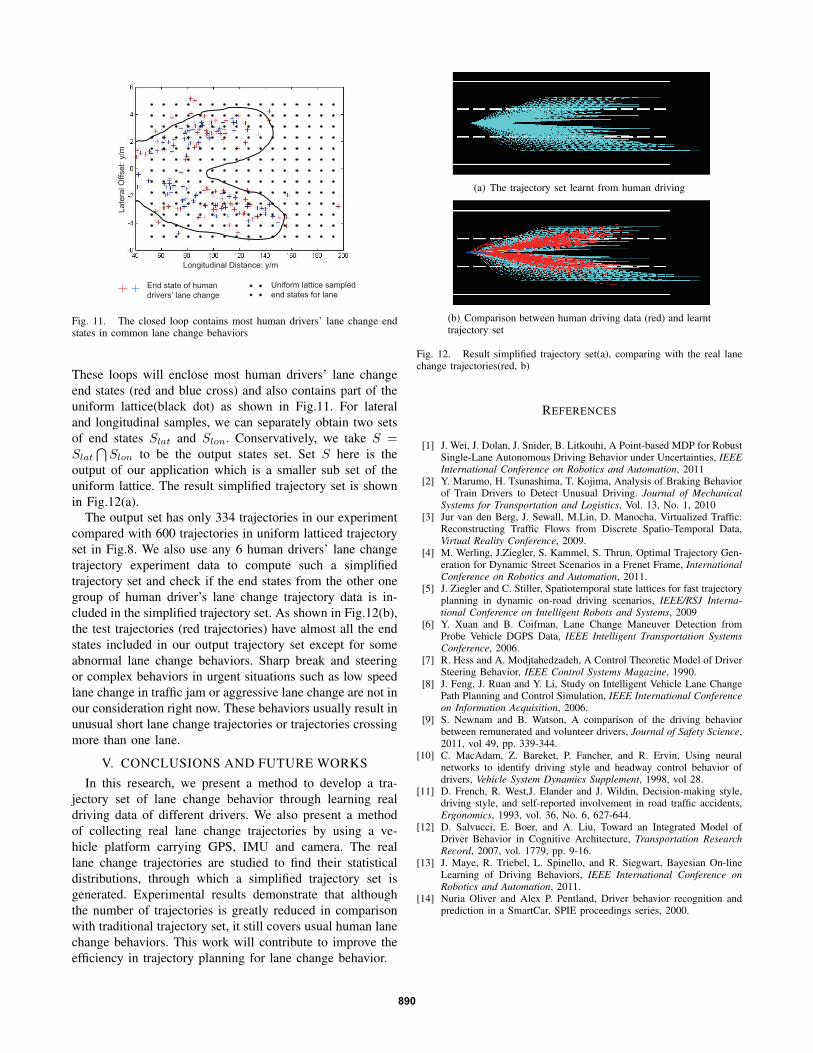
output of our application which is a smaller sub set of theuniform lattice. The result simplified trajectory set is shownin Fig.12(a).
The output set has only 334 trajectories in our experimentcompared with 600 trajectories in uniform latticed trajectoryset in Fig.8. We also use any 6 human drivers’ lane changetrajectory experiment data to compute such a simplifiedtrajectory set and check if the end states from the other onegroup of human driver’s lane change trajectory data is in-cluded in the simplified trajectory set. As shown in Fig.12(b),the test trajectories (red trajectories) have almost all the endstates included in our output trajectory set except for someabnormal lane change behaviors. Sharp break and steeringor complex behaviors in urgent situations such as low speedlane change in traffic jam or aggressive lane change are not inour consideration right now. These behaviors usually result inunusual short lane change trajectories or trajectories crossingmore than one lane.
V. CONCLUSIONS AND FUTURE WORKSIn this research, we present a method to develop a tra-
jectory set of lane change behavior through learning realdriving data of different drivers. We also present a methodof collecting real lane change trajectories by using a ve-hicle platform carrying GPS, IMU and camera. The reallane change trajectories are studied to find their statisticaldistributions, through which a simplified trajectory set isgenerated. Experimental results demonstrate that althoughthe number of trajectories is greatly reduced in comparisonwith traditional trajectory set, it still covers usual human lanechange behaviors. This work will contribute to improve theefficiency in trajectory planning for lane change behavior.
(a) The trajectory set learnt from human driving
(b) Comparison between human driving data (red) and learnttrajectory set
Fig. 12. Result simplified trajectory set(a), comparing with the real lanechange trajectories(red, b)
REFERENCES
[1] J. Wei, J. Dolan, J. Snider, B. Litkouhi, A Point-based MDP for RobustSingle-Lane Autonomous Driving Behavior under Uncertainties, IEEEInternational Conference on Robotics and Automation, 2011
[2] Y. Marumo, H. Tsunashima, T. Kojima, Analysis of Braking Behaviorof Train Drivers to Detect Unusual Driving. Journal of MechanicalSystems for Transportation and Logistics, Vol. 13, No. 1, 2010
[3] Jur van den Berg, J. Sewall, M.Lin, D. Manocha, Virtualized Traffic:Reconstructing Traffic Flows from Discrete Spatio-Temporal Data,Virtual Reality Conference, 2009.
[4] M. Werling, J.Ziegler, S. Kammel, S. Thrun, Optimal Trajectory Gen-eration for Dynamic Street Scenarios in a Frenet Frame, InternationalConference on Robotics and Automation, 2011.
[5] J. Ziegler and C. Stiller, Spatiotemporal state lattices for fast trajectoryplanning in dynamic on-road driving scenarios, IEEE/RSJ Interna-tional Conference on Intelligent Robots and Systems, 2009
[6] Y. Xuan and B. Coifman, Lane Change Maneuver Detection fromProbe Vehicle DGPS Data, IEEE Intelligent Transportation SystemsConference, 2006.
[7] R. Hess and A. Modjtahedzadeh, A Control Theoretic Model of DriverSteering Behavior, IEEE Control Systems Magazine, 1990.
[8] J. Feng, J. Ruan and Y. Li, Study on Intelligent Vehicle Lane ChangePath Planning and Control Simulation, IEEE International Conferenceon Information Acquisition, 2006.
[9] S. Newnam and B. Watson, A comparison of the driving behaviorbetween remunerated and volunteer drivers, Journal of Safety Science,2011, vol 49, pp. 339-344.
[10] C. MacAdam, Z. Bareket, P. Fancher, and R. Ervin, Using neuralnetworks to identify driving style and headway control behavior ofdrivers, Vehicle System Dynamics Supplement, 1998, vol 28.
[11] D. French, R. West,J. Elander and J. Wildin, Decision-making style,driving style, and self-reported involvement in road traffic accidents,Ergonomics, 1993, vol. 36, No. 6, 627-644.
[12] D. Salvucci, E. Boer, and A. Liu, Toward an Integrated Model ofDriver Behavior in Cognitive Architecture, Transportation ResearchRecord, 2007, vol. 1779, pp. 9-16.
[13] J. Maye, R. Triebel, L. Spinello, and R. Siegwart, Bayesian On-lineLearning of Driving Behaviors, IEEE International Conference onRobotics and Automation, 2011.
[14] Nuria Oliver and Alex P. Pentland, Driver behavior recognition andprediction in a SmartCar, SPIE proceedings series, 2000.
890