Embed Size (px)
Citation preview

Topic 2.4 – Analogue Communications.2.4.1 General Amplifier Systems.
Learning Objectives:
At the end of this topic you will be able to;
understand that amplifiers increase the power (VI) of signals; describe the function of the following subsystems of a typical
amplifier system:o signal source (e.g. microphone)o preamplifier (i.e. voltage amplifier)o mixero power (current) amplifiero loudspeaker
select and use the formula ;
understand what is meant by the bandwidth of an amplifier; measure the bandwidth of an amplifier from a graph of
voltage gain against frequency; explain and draw graphs to illustrate the meaning of
output clipping for a given input signal; understand the trade-off between gain and bandwidth
and the role of multiple stage voltage amplifiers in retaining bandwidth.
1
GCSE Electronics.Unit E2 : Applications of Electronics
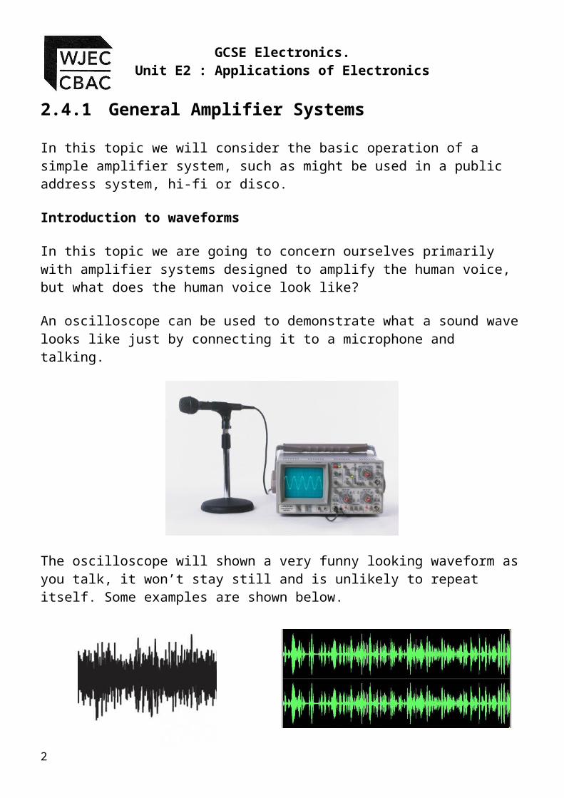
2.4.1 General Amplifier SystemsIn this topic we will consider the basic operation of a simple amplifier system, such as might be used in a public address system, hi-fi or disco.
Introduction to waveforms
In this topic we are going to concern ourselves primarily with amplifier systems designed to amplify the human voice, but what does the human voice look like?
An oscilloscope can be used to demonstrate what a sound wave looks like just by connecting it to a microphone and talking.
The oscilloscope will shown a very funny looking waveform as you talk, it won’t stay still and is unlikely to repeat itself. Some examples are shown below.
2

Topic 2.4 – Analogue Communications.2.4.1 General Amplifier Systems.
The reason that the sound wave looks so strange is that it is a very complex wave made up of waves of many different frequencies all added together. Thinking of musical instruments, we know that they sound very different. If we display the same note being played from four popular instruments we can see why they sound different.
Each waveform repeats regularly, but the waveforms look completely different. The range of frequencies in each waveform is completely different. The study of sound waves is a university course in its own right. All you need to know is that sound waves are complex waves made up of many simple waves added together.
Consider a simple waveform called a sine wave. It has the following appearance.
We will use this simple waveform to study the operation of a basic amplifier system.
3

GCSE Electronics.Unit E2 : Applications of Electronics
Amplitude of a wave
An AC signal contains both positive and negative voltages. This is the first time that we have come across this situation, and may lead to confusion unless we adopt a consistent understanding of how to describe the waveform.
We will define amplitude as:
“the maximum ‘height’ of the positive part of a wave.”
It is sometimes referred to as peak value or maximum value. In electronics, it is usually measured in volts.
The following diagram illustrates three waves with increasing amplitude.
Our definition of amplitude is consistent with the work carried out earlier in Topic 2.1 when we considered astable waveforms. The output of an astable circuit was a square wave which went from zero to a maximum positive voltage. It had no negative half, so its amplitude was equal to the whole positive height of the square wave.
4

Topic 2.4 – Analogue Communications.2.4.1 General Amplifier Systems.
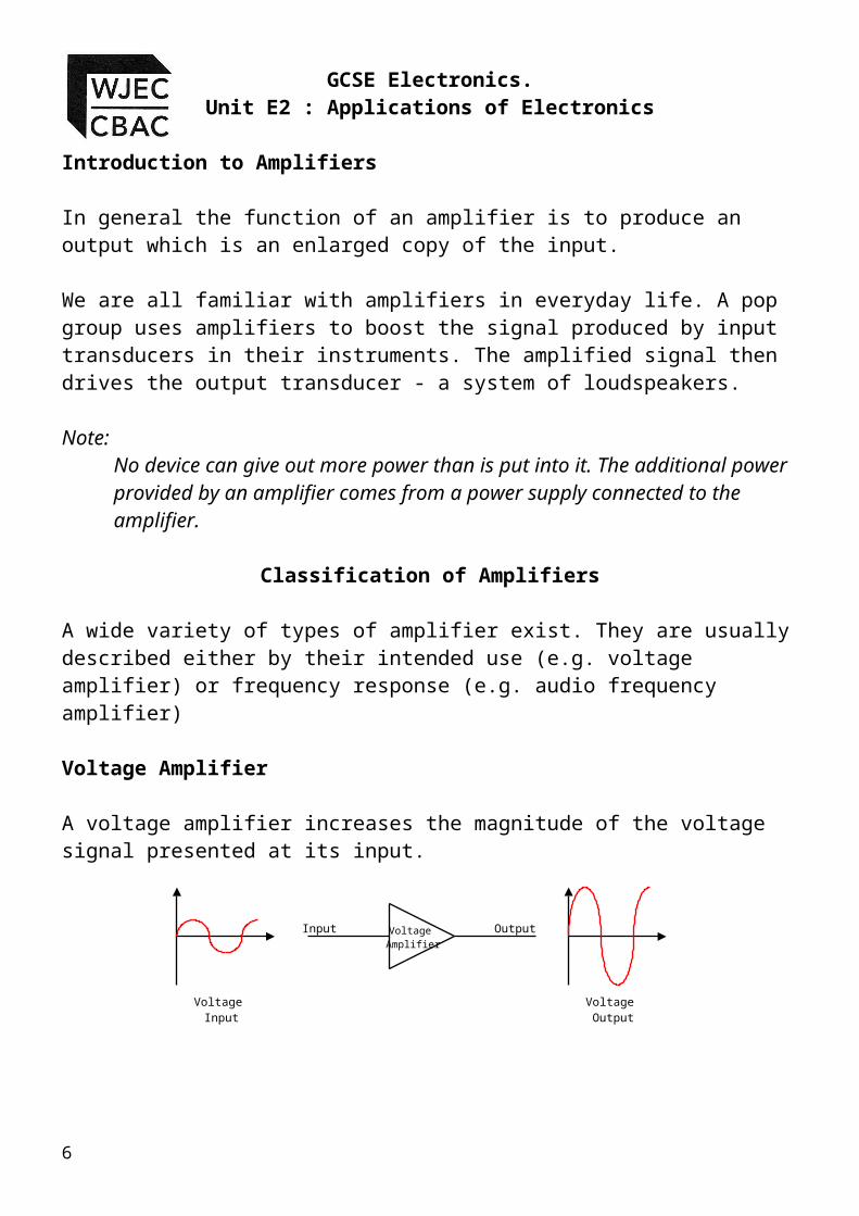
Introduction to Amplifiers
In general the function of an amplifier is to produce an output which is an enlarged copy of the input.
We are all familiar with amplifiers in everyday life. A pop group uses amplifiers to boost the signal produced by input transducers in their instruments. The amplified signal then drives the output transducer - a system of loudspeakers.
Note:No device can give out more power than is put into it. The additional power provided by an amplifier comes from a power supply connected to the amplifier.
Classification of Amplifiers
A wide variety of types of amplifier exist. They are usually described either by their intended use (e.g. voltage amplifier) or frequency response (e.g. audio frequency amplifier)
Voltage Amplifier A voltage amplifier increases the magnitude of the voltage signal presented at its input.
5
Voltage Amplifier
Voltage Input
Voltage Output
Input Output
GCSE Electronics.Unit E2 : Applications of Electronics
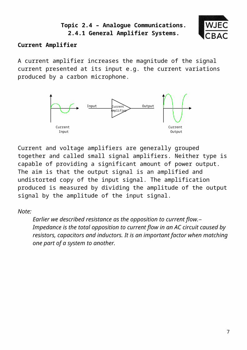
Current Amplifier
A current amplifier increases the magnitude of the signal current presented at its input e.g. the current variations produced by a carbon microphone.
Current and voltage amplifiers are generally grouped together and called small signal amplifiers. Neither type is capable of providing a significant amount of power output. The aim is that the output signal is an amplified and undistorted copy of the input signal. The amplification produced is measured by dividing the amplitude of the output signal by the amplitude of the input signal.
Note: Earlier we described resistance as the opposition to current flow. Impedance is the total opposition to current flow in an AC circuit caused by resistors, capacitors and inductors. It is an important factor when matching one part of a system to another.
6
Current Amplifier
Current Input
Current Output
Input Output
Topic 2.4 – Analogue Communications.2.4.1 General Amplifier Systems.
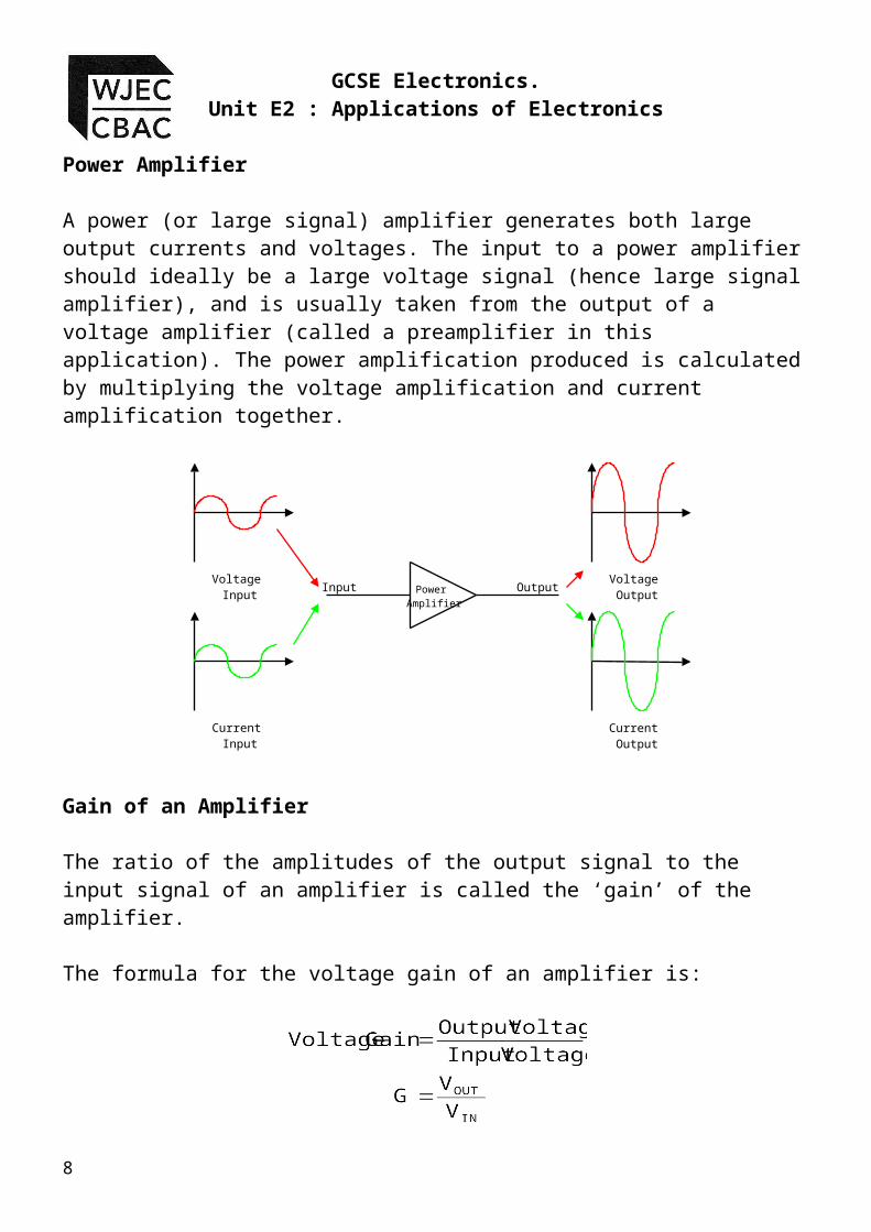
Power Amplifier
A power (or large signal) amplifier generates both large output currents and voltages. The input to a power amplifier should ideally be a large voltage signal (hence large signal amplifier), and is usually taken from the output of a voltage amplifier (called a preamplifier in this application). The power amplification produced is calculated by multiplying the voltage amplification and current amplification together.
Gain of an Amplifier
The ratio of the amplitudes of the output signal to the input signal of an amplifier is called the ‘gain’ of the amplifier.
The formula for the voltage gain of an amplifier is:
7
Power Amplifier
Voltage Input
Voltage OutputInput Output
Current Input
Current Output
GCSE Electronics.Unit E2 : Applications of Electronics
Examples:1. A voltage amplifier has an output voltage of 200mV. What is the
voltage gain of the amplifier if the input voltage is 5mV?
2. If VIN = 22mV and G = 40, What is the value of VOUT:
3. A voltage amplifier has an output voltage of 540mV. What is the input voltage when the voltage gain of the amplifier is 20?
Audio Frequency Amplifiers Audio frequency (AF) amplifiers amplify AC signals in the range 20Hz to 20kHz.
The frequency response of an amplifier is best described by a graph showing how the gain of an amplifier varies with different signal frequencies.
The typical voltage gain-frequency curve for an audio amplifier is shown below.
8

Topic 2.4 – Analogue Communications.2.4.1 General Amplifier Systems.
The bandwidth of the amplifier is defined as the range of frequencies within which the voltage gain does not fall below (i.e. 0.7) of its maximum value, as shown above.
Radio Frequency Amplifiers
Radio frequency (RF) amplifiers operate above 20kHz and are 'tuned' to amplify a narrow band of frequencies around a centre frequency which could be as high as 100 MHz.
Video (Wideband) Frequency Amplifiers
Video or wideband amplifiers can amplify a wide band of frequencies ranging from DC to 50MHz.
We have described the basic properties of the basic types of amplifier, i.e. Voltage, Current, Power and Audio. In this introductory course we will only be considering the voltage amplifier in any detail.
9

GCSE Electronics.Unit E2 : Applications of Electronics
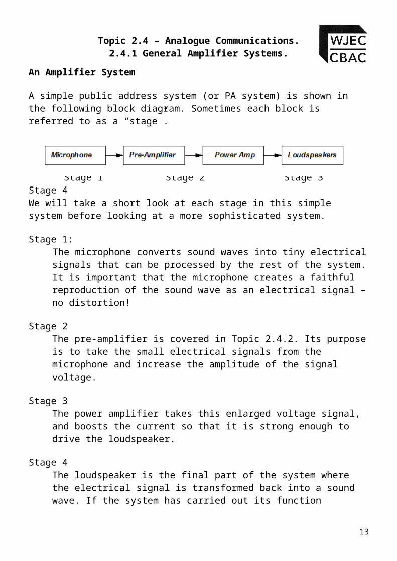
An Amplifier System
A simple public address system (or PA system) is shown in the following block diagram. Sometimes each block is referred to as a “stage”.
Stage 1 Stage 2 Stage 3 Stage 4
We will take a short look at each stage in this simple system before looking at a more sophisticated system.
Stage 1:The microphone converts sound waves into tiny electrical signals that can be processed by the rest of the system. It is important that the microphone creates a faithful reproduction of the sound wave as an electrical signal – no distortion!
Stage 2The pre-amplifier is covered in Topic 2.4.2. Its purpose is to take the small electrical signals from the microphone and increase the amplitude of the signal voltage.
Stage 3The power amplifier takes this enlarged voltage signal, and boosts the current so that it is strong enough to drive the loudspeaker.
Stage 4The loudspeaker is the final part of the system where the electrical signal is transformed back into a sound wave. If the system has carried out its function correctly the emerging sound wave will be an undistorted but amplified version of the original.
10

Topic 2.4 – Analogue Communications.2.4.1 General Amplifier Systems.
A more sophisticated PA system would allow a number of inputs to be connected
For example a band would have several microphone inputs and guitar pick-up inputs. These inputs would need to be faded in or out individually. Consider the following block diagram
You should notice there are two additions to the simple PA system.The first is a music source and the second is a mixer.
The Mixer is covered in Topic 2.4.3. Its function is to add together electrical signals from microphones or pick-ups from electric guitars or backing tracks from a CD player. Most music sources produce a much larger signal than a microphone and do not need a pre-amplifier. In a real system each microphone would have its own pre-amplifier.
If we try to amplify the signal too much the system will not be able to provide the voltage required. This results in distortion of the output signal, called clipping distortion.
Typically the output voltage maximum is between 1-2V less than that of the power supply. For example if the power supply was ±15V, then the maximum output would be limited to around ±13V. If the same amplifier was then connected to a ±5V supply, without making any changes to the circuit, the maximum output would then be limited to just ±3V. We call this effect saturation. In exam questions you will be provided with the saturation values.
11

GCSE Electronics.Unit E2 : Applications of Electronics
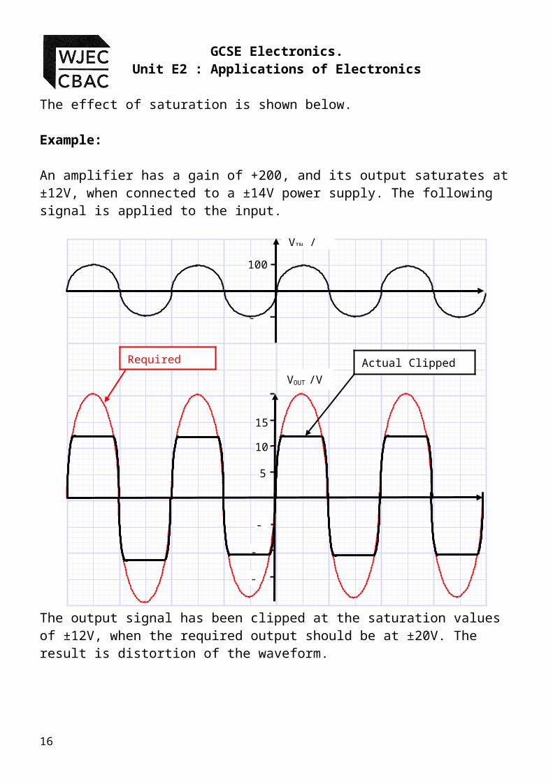
The effect of saturation is shown below.
Example:
An amplifier has a gain of +200, and its output saturates at ±12V, when connected to a ±14V power supply. The following signal is applied to the input.
The output signal has been clipped at the saturation values of ±12V, when the required output should be at ±20V. The result is distortion of the waveform.
12
VIN /mV
VOUT /V
-5
-10
-15
5
10
15
100
-100
Required Output Actual Clipped Output
Topic 2.4 – Analogue Communications.2.4.1 General Amplifier Systems.
There are two ways in which this type of distortion can be avoided:
i. increase the power supply voltage range to at least ±22V for example in this case. {However this is only possible if the amplifier can operate at this voltage level.}
ii. decrease the gain of the amplifier so that the maximum signal output is limited to ±12V.
Bandwidth
The majority of amplifier designs are built to amplify AC signals. One of the features of an AC signal is that not only can its amplitude change, but also it’s frequency. An amplifier must boost the amplitude of the signal but leave the frequency of the signal unchanged.
Amplifiers contain components that respond differently to different frequencies, so there is a problem trying to design one amplifier to cover the entire frequency range.
Amplifiers are designed to allow a specific range of frequencies to be amplified, e.g.
a telephone amplifier is designed to accept frequencies from 300Hz to 3KHz;
a music amplifier is designed to accept frequencies from 20Hz to 20kHz
If we were to pass a video signal, with frequencies as high as 6MHz, through an audio amplifier, designed for frequencies up to 20kHz, then we would not obtain the correct output.
The range of frequencies that can be amplified correctly is defined as the bandwidth of the amplifier.
The bandwidth of an amplifier is the range of frequencies that can be amplified to more than (70%) of the maximum gain.
13

GCSE Electronics.Unit E2 : Applications of Electronics
This is easier to see if we look at the typical response of an amplifier as the frequency is increased.
A common mistake made by candidates in examinations is to think of the bandwidth as being the range of frequencies where 100% gain is achieved.
The 70% or comes from a mathematical analysis of the point where half the original signal power is lost.
Fortunately in an examination you will not be asked to prove this.
Here are some examples to show you what is required.
14
1 10 100 1000 10k 100k 1M 10M frequency (Hz)
100
80
60
40
20
Voltage Gain (%)
Bandwidth

Topic 2.4 – Analogue Communications.2.4.1 General Amplifier Systems.
Examples:
1. An amplifier has the following frequency response. Use the graph to estimate the bandwidth of this amplifier. Show on the graph how you obtain your result.
Solution :
Step 1: Work out or 70% of the maximum gain.
Step 2: Now draw a horizontal line across the graph from a gain of 280, as shown by the red line below:
Step 3 : Now draw a vertical line down to the frequency axis from the intercept of the original graph and the red line you have just drawn. This is shown in blue on the graph:
15
GCSE Electronics.Unit E2 : Applications of Electronics
Step 4: Read off the bandwidth from the intercept with the frequency axis, in this case 25 kHz.
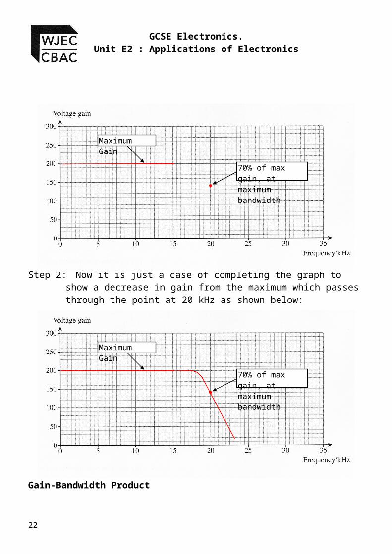
2. A pre-amplifier with a voltage gain of 200, has a bandwidth of 20kHz. Use the axes provided to sketch the frequency response of the amplifier.
Step 1: From the question we know the maximum gain will be 200. If the bandwidth is 20 kHz then we know that at 20 kHz the gain will be or 70% of 200 = 140.
This gives us the critical parts of the response graph, as shown below;
16
Maximum Gain
70% of max gain, at maximum bandwidth
Topic 2.4 – Analogue Communications.2.4.1 General Amplifier Systems.
Step 2: Now it is just a case of completing the graph to show a decrease in gain from the maximum which passes through the point at 20 kHz as shown below:
Gain-Bandwidth Product
The bandwidth of an amplifier is closely linked to its voltage gain. The higher the voltage gain, the smaller its bandwidth will be. This leads to another measure of the performance for amplifiers called the gain-bandwidth product. For example if a pre-amplifier has a gain-bandwidth product of 1MHz, this means that:
i. For a gain of 1, the bandwidth will 1MHzii. For a gain of 10, the bandwidth will be 100kHziii. For a gain of 100, the bandwidth will be 10kHziv. For a gain of 1000, The bandwidth will be 1kHz etc
In each example the gain x bandwidth = 1 MHz. As the voltage gain gets bigger, the bandwidth gets smaller.
17
Maximum Gain
70% of max gain, at maximum bandwidth

GCSE Electronics.Unit E2 : Applications of Electronics
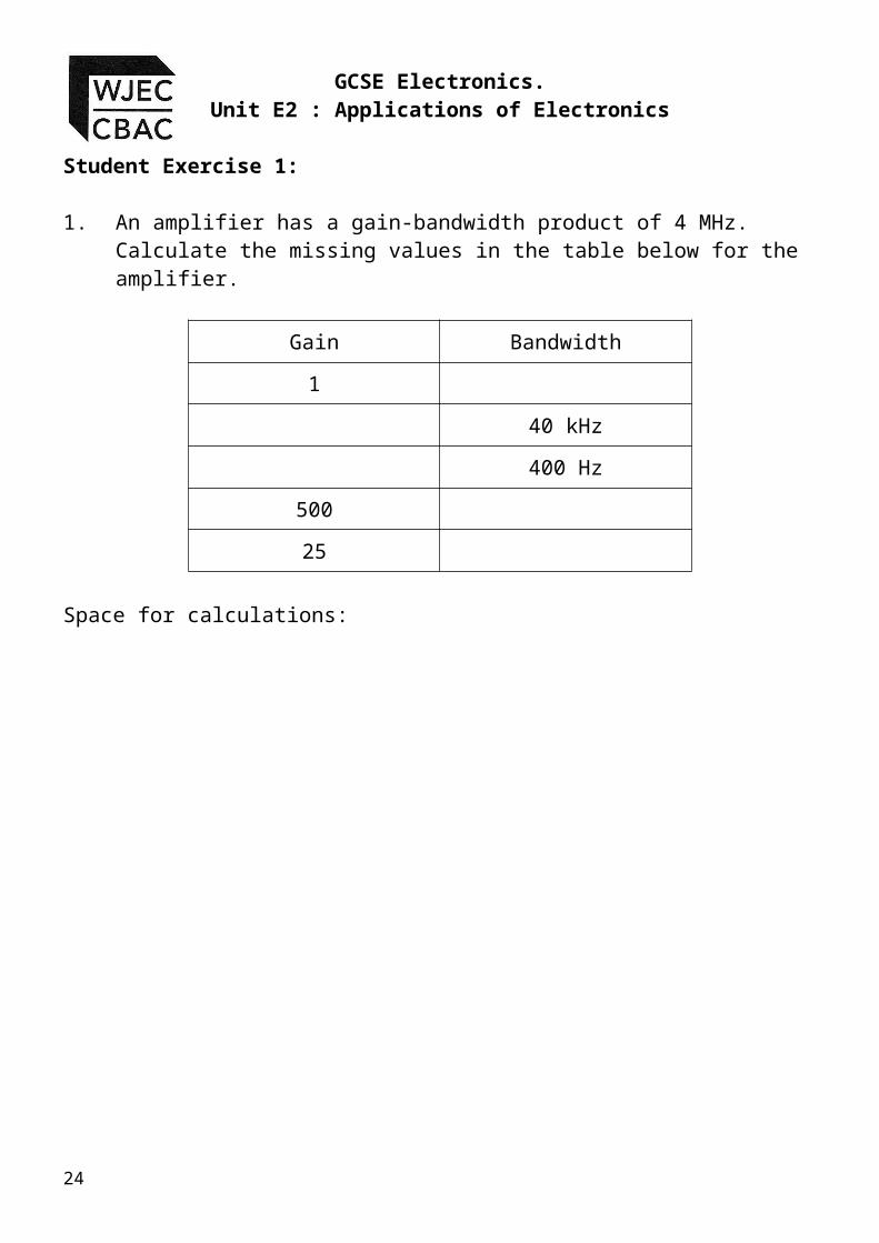
Student Exercise 1:
1. An amplifier has a gain-bandwidth product of 4 MHz. Calculate the missing values in the table below for the amplifier.
Gain Bandwidth1
40 kHz400 Hz
50025
Space for calculations:
18

Topic 2.4 – Analogue Communications.2.4.1 General Amplifier Systems.
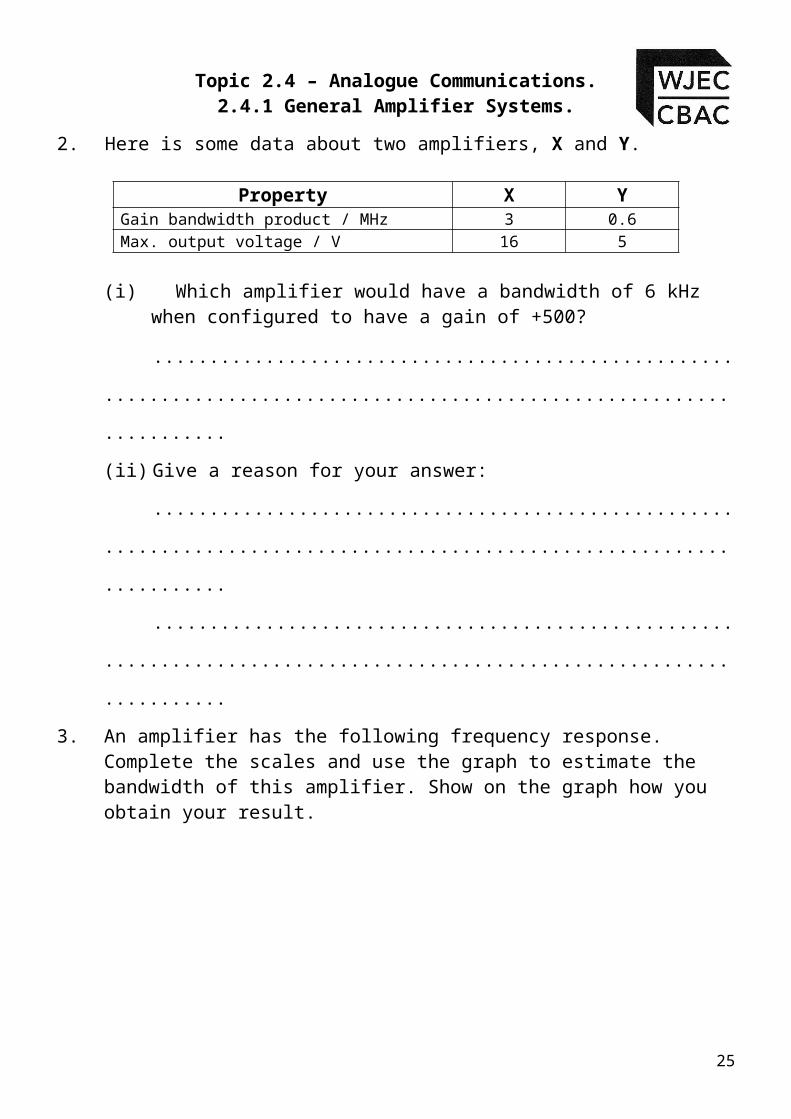
2. Here is some data about two amplifiers, X and Y.
Property X YGain bandwidth product / MHz 3 0.6Max. output voltage / V 16 5
(i) Which amplifier would have a bandwidth of 6 kHz when configured to have a gain of +500?..................................................................................................
.....................(ii) Give a reason for your answer:
.......................................................................................................................
.......................................................................................................................
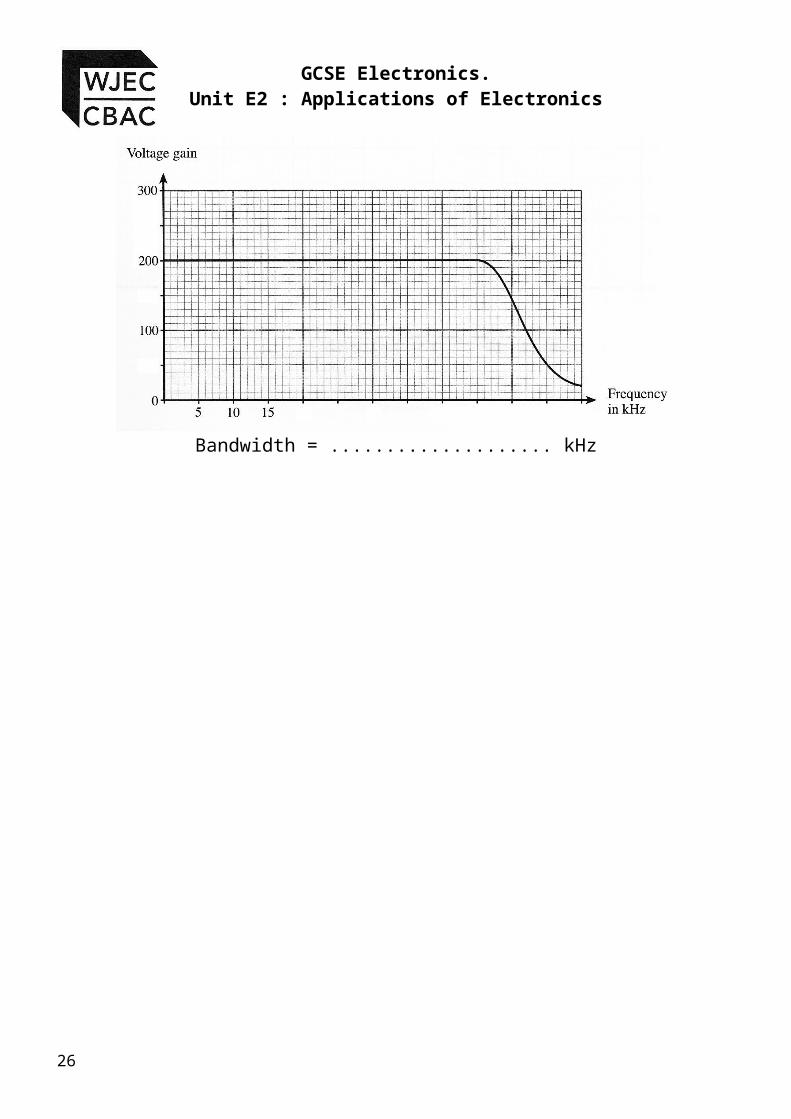
3. An amplifier has the following frequency response. Complete the scales and use the graph to estimate the bandwidth of this amplifier. Show on the graph how you obtain your result.
Bandwidth = .................... kHz
19

GCSE Electronics.Unit E2 : Applications of Electronics
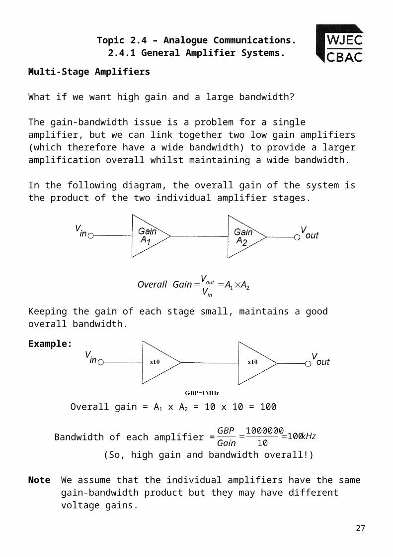
Multi-Stage Amplifiers
What if we want high gain and a large bandwidth?
The gain-bandwidth issue is a problem for a single amplifier, but we can link together two low gain amplifiers (which therefore have a wide bandwidth) to provide a larger amplification overall whilst maintaining a wide bandwidth.
In the following diagram, the overall gain of the system is the product of the two individual amplifier stages.
Keeping the gain of each stage small, maintains a good overall bandwidth.Example:
Overall gain = A1 x A2 = 10 x 10 = 100
Bandwidth of each amplifier =(So, high gain and bandwidth overall!)
Note We assume that the individual amplifiers have the same gain-bandwidth product but they may have different voltage gains.
To find the overall bandwidth divide the gain-bandwidth product by the highest individual gain.
20
21 AAVVGainOverall
in
out

Topic 2.4 – Analogue Communications.2.4.1 General Amplifier Systems.
Homework Questions 1
1. For the amplifier shown below, calculate Vout, when Vin = 1mV and the gain of the amplifier = 35.
Vout =
2. For the amplifier shown below, calculate the gain of
the amplifier if Vout=50mV and Vin=2mV.
Gain =
3. Complete the following table with the missing values.Vin Gain G Vout
5mV 60mV2mV 100
30 120mV10 1V
6mV 2520µV 400
4. A multistage amplifier consists of 2 amplifiers, one having a gain of 10 and the second having a gain of 20. They each have a gain-bandwidth product of 2MHz.
Overall gain = ………………; Overall bandwidth =………………
21
GCSE Electronics.Unit E2 : Applications of Electronics
Solutions to Student Exercises
Exercise 1:
1.Gain Bandwidth
1 4MHz100 40 kHz
10000 400 Hz500 8 kHz25 160 kHz
2.(i) Amplifier X
(ii) 6kHz x 500 = 3MHz = gain-bandwidth product of the amplifier, and this corresponds to amplifier X. Amplifier Y only has a GBP of 0.6MHz and therefore could not have this gain for this bandwidth.
3.
Bandwidth = .......50............. kHz
22

Topic 2.4 – Analogue Communications.2.4.1 General Amplifier Systems.
Homework Questions 1
1.
2.
3. Complete the following table with the missing values.
Vin A Vout
5mV 12 60mV2mV 100 200mV4mV 30 120mV
100mV 10 1V6mV 25 150mV20µV 400 8mV
4. Overall gain = G1 G2 = 10 20 = 200
Now for some examination style questions.
23
GCSE Electronics.Unit E2 : Applications of Electronics
Examination Style Questions
1. The block diagram for a public address system used in a school hall is shown below.
(a)Write the names of the four blocks in the boxes on the above diagram.
Choose from the following list.
Power Amplifier Loudspeaker Pre-amplifier Comparator Microphone[4]
(b) The deputy headteacher of the school plays a guitar during assembly, and wants to add a guitar output into the public address system. Redraw the PA system to show how this second input can be added to the system. You may add any additional blocks you may need.
[2]
(c) The pre-amplifier block consisted of a multi-stage amplifier made up of two amplifiers each having a gain of 20 and gain bandwidth product (GBP) of 1MHz. calculate:
(i) the overall gain……………………………………………………………………..
(ii) the overall bandwidth ……………………………………………………………
[3]
24
Topic 2.4 – Analogue Communications.2.4.1 General Amplifier Systems.
2. The block diagram for a disco sound system is shown below.
(a) (i) Name one possible signal source.
...............................................................................................................................................[1]
(ii) Why is a pre-amplifier needed?
...............................................................................................................................................
...............................................................................................................................................[1]
(iii) Why is a power amplifier needed?
...............................................................................................................................................
...............................................................................................................................................[1]
(b) The gain of the pre-amplifier is measured as the frequency of a signal source is varied.The results are shown in the following table.
25
GCSE Electronics.Unit E2 : Applications of Electronics
(i) On the grid below, draw a graph of gain against frequency.
[3]
(ii) Mark carefully on the graph, the points at which the bandwidth of the amplifier would be measured.
[2]
(iii) Hence estimate the bandwidth of this preamplifier.
Bandwidth is ....................................................... kHz[1]
(c) The amplitude of the input voltage at a frequency of 5kHz was found to be 5mV. Calculate the amplitude of the output voltage at this frequency.
...............................................................................................................................................
............................................................................................................................................... [2]
26
Topic 2.4 – Analogue Communications.2.4.1 General Amplifier Systems.
3. (a) A public address system contains some of the following sub-systems:
loudspeaker power amplifier demodulator
preamplifier microphone
(i) Here is an outline of the block diagram for the system. Complete it by adding the names of the appropriate subsystems in the list to the correct block.
[4]
(ii) How does the job of the preamplifier differ from that of the power amplifier?
................................................................................................................................................
................................................................................................................................................
................................................................................................................................................[2]
27

GCSE Electronics.Unit E2 : Applications of Electronics
Self Evaluation Review
Learning ObjectivesMy personal review of these objectives:
understand that amplifiers increase the power (VI) of signals;describe the function of the following subsystems of a typical amplifier system: signal source (e.g. microphone), preamplifier (i.e. voltage amplifier), mixer, power (current) amplifier, loudspeaker
select and use the formula ;
understand what is meant by the bandwidth of an amplifier;measure the bandwidth of an amplifier from a graph of voltage gain against frequency;explain and draw graphs to illustrate the meaning of output clipping for a given input signal;understand the trade-off between gain and bandwidth and the role of multiple stage voltage amplifiers in retaining bandwidth.
Targets: 1.
………………………………………………………………………………………………………………
………………………………………………………………………………………………………………
2. ………………………………………………………………………………………………………………
………………………………………………………………………………………………………………
28

Topic 2.4 – Analogue Communications.2.4.1 General Amplifier Systems.
29