Embed Size (px)
Citation preview
D R A F T C O P Y - FOR COMMITTEE USE ONLY
API B u l l e t i n 2502
A
API
RECOMMENDED PRACTICES
for
LEASE AUTOMATIC CUSTODY TRANSFER,-.
^~ V -^ ^ V- -A \\ r?v. V S r N \\\\ V-i)
AMERICAN PETROLEUM INSTITUTE
New York, N. Y.
OIL C C N S ^ ^
CASE _ ^
API RECOMMENDED PRACTICE FOR LEASE AUTOMATIC CUSTODY TRANSFER
Foreword
a. This Recommended Practice, prepared under the sponsorship of the API
Committee on Crude-Oil Measurements, summarizes information that has been gained
from a study of the experimental and operating systems devised by various compan
ies for automatic custody transfer of crude oil from producing leases. "Lease
automatic custody transfer" (LACT) consists of the measurement and running of
oil from the producers' tanks to the connected pipeline on an automatic or
unattended basis. This Recommended Practice is issued for the purpose of
describing currently acceptable methods for LACT. The practices recommended
are considered sound and reliable, but i t should be expected that improvements
will be made.
b. Throughout this Recommended Practice, references are made to API
Standard 2500; "Measuring, Sampling, and Testing Crude Oil"; API Standard
2501: "Crude-Oil Tank Measurement and Calibration"; and API Standard 1101;
"Standard for the Installation, Proving, and Operation of Positive-Displacement
Meters in Liquid-Hydrocarbon Service" (short t i t l e : Petroleum PD Mqfce* Cocje).
I t is intended that these standards be used in a l l cases where they are applica
ble, in order to form a sound basis for accomplishing satisfactory automatic
custody transfer.
c. Until a few years ago, a l l crude oil run from producers' tanks was
measured, sampled, and tested by the use of hand tools. For about 30 years
the American Petroleum Institute has continuously studied and improved these
methods to make them as practical and accurate as possible. In 1954 the Insti
tute approved the use of automatic indicating gauges and thermometers on a
mutual-agreement basis, and industry is finding them to be accurate and preferable
2.
to hand tools in many instances. In recent years, producers have installed
automatic devices at lease tank batteries in quite a few fields to eliminate
certain repetitious and time-consuming operations.
d. In many fields i t has become apparent that lease automatic custody
transfer offers the potential advantages of:
1. Reduction in required lease storage (which could also mean
less evaporation losses and less investment in stored o i l ) .
2. Improvement of measurement accuracy.
3. Reduction of the possibility of error in measurement or in
quantity computation.
4. Simplification of computation and accounting procedures.
5. Reduction of time required by pumpers and gaugers in making
measurements.
6. Improved scheduling of runs on a predetermined basis.
7. Allowing maximum use of other automatic equipment installed
primarily for the production operations.
8. Increased operating efficiency and control.
e. The apparent disadvantages are:
1. Lease equipment needs more precise design, engineering, and
maintenance.
2. A more complex system is required.
f. Early standardization of industry practice relating to methods and
equipment used i n lease automatic custody transfer is very desirable for three
principal reasons:
3.
1. To f a c i l i t a t e establishment of mutual agreement between
parties concerned in automatic custody transfer.
2. To reduce the amount of engineering time required i n design
of automatic custody transfer installations.
3. To f a c i l i t a t e the periodic inspection of automatic custody
transfer installations for insuring satisfactory performance.
I t is hoped that the information contained in the Recommended Practice
w i l l be of assistance in establishing mutual agreement between parties interested
in installation of systems operating in lease automatic custody transfer.
g. The material contained herein does not constitute an o f f i c i a l code or
standard of the American Petroleum Insti t u t e ; nor is i t intended that this
material should become part of API Standard 2500 u n t i l such time as industry
practice may have become established and the principles outlined in this Recom
mended Practice and other principles which may develop in practice have been
more generally proved.
h. The American Petroleum Institute takes no position as to whether or
not any method contained herein is covered by an existing patent, nor as to the
va l i d i t y of any patent alleged to cover any such method. Furthermore, nothing
contained in this Recommended Practice grants any right, by implication or other
wise, for the manufacture, sale, or use in connection with any method, apparatus,
or product covered by letters patent; nor does i t insure anyone against l i a b i l i t y
for infringement of letters patent. This Recommended Practice may be used by any
one desiring to do so, but the sponsor shall not be held responsible or liable in
any way either for any loss or damage resulting therefrom, or for any violation of
any federal, state, or municipal regulations with which i t may conflict.
4.
SECTION I - GENERAL
INTRODUCTION
1. This Recommended Practice is intended to form a basis for mutual agree
ment between parties concerned in automatic custody transfer of crude o i l from
producing leases to the connected pipeline. I t recommends practices which should
provide accurate and reliable measurement and suitable protection against mis-
measurement or otherwise faulty operation. LACT, as defined herein, may be used
where mutually agreeable to the parties concerned i n the transaction and where
government or other regulations w i l l permit.
2. These recommendations are not meant i n any way to be restrictive or to
retard future development of methods found to be either more suitable or more
practical.
DEFINITIONS
1. Lease Automatic Custody Transfer. A Lease Automatic Custody Transfer
system is defined as an arrangement of equipment designed for the unattended
transfer of l i q u i d hydrocarbons from producing leases to the transporting car
r i e r while providing proper means for quality determination, net-volume determi
nation, and fail-safe operation; and while meeting requirements of accuracy and
dependability as defined in Recommended Practices for Lease Automatic Custody
Transfer.
2. Cycle. F i l l i n g and running of one measuring tank.
3. Dump. That volume of o i l (corrected or uncorrected for temperature)
which is delivered to. the pipeline in one complete cycle of the measuring tank,
or the running of that volume of o i l .
4. Run. A series of dumps or periods of meter measurement, either inter
rupted or uninterrupted, which are covered by a single-run ticket.
5.
BASIC SYSTEM REQUIREMENTS
1. General. There are a great number of basic a l t e r n a t i v e arrangements
which could be used to accomplish lease automatic custody transfer with s a t i s
factory r e s u l t s . I t i s the purpose of th i s section to describe the basic
requirements that should be met by a l l systems. Optional features may be
desirable under certain conditions. The basic systems are divided i n t o :
(a) measuring tank type systems and (b) p o s i t i v e displacement metering systems.*
2. Requirements fo r A l l Types. The following l i s t contains the general
requirements of any system f o r automatic custody transfer. Some features are
indicated as optional, or to be used by mutual agreement where conditions warrant;
and others are applicable where required by regulations:
a. S t a b i l i t y of O i l . The lease o i l handling arrangement must be such
that the o i l when measured i s s u f f i c i e n t l y stable and free from
v o l a t i l e fractions to permit accurate measurement and l a t e r transpor
t a t i o n without abnormal or excessive losses.
b. Volume Correction. Provision must be made for accurate determina
t i o n and recording of uncorrected volume and applicable temperature,
or of temperature-corrected volume. The over-all accuracy of the
system must equal or surpass present manual methods.
c. Sampling. Provision must be made f o r representative sampling of
the o i l transferred for determination of API g r a v i t y and the BS&W
(sediment and water) content.**
•Velocity type and mass-flow meters may at some future time be adapted to LACT operations.
••There i s some work i n progress attempting to perfect new means and techniques of determining the BS&W content of o i l that has been run, f o r use i n l i e u of conventional sampling and t e s t i n g .
6.
d. Merchantable Oil. Means must be provided if required by either
party to give adequate assurance that the oil is merchantable
before i t is run.
e. Delivery. If required by either party, control shall be provided
over the time of entry of the oil into the carrier's sysi:em.
f. Allowable. Where regulations require, control shall be provided
to stop the flow of oil into the carrier's system at or prior to
the time that the allowable is run.
g. Tail-Safe" Features. The control and recording system nust
include "fail-safe features" that will provide adequate assurance
against mismeasurement in the event of power failure or :he f a i l
ure of the system's component parts.
h. Tampering. All necessary controls and equipment must be enclosed
and sealed, or otherwise be so arranged as to provide assurance
against, or evidence of, accidental or purposeful mismeaaurement
resulting from tampering.
i . Calibration. All components of the system which require periodic
calibration and inspection for proof of continued accuracy must
be readily accessible. The frequency and procedures to be used
should be agreeable mutually to the parties concerned.
j . Standards. All usual codes, regulations, and standards covering
measurement of crude oil shall b« UfeT -'ijfjjffir appl i cable. This
sifically includes API Standard 2500, "Standard 2SQ1 and
Standard 1X01.
7.
TEMPERATURE MEASUREMENT
1. Temperature Correction. Correct use of devices to indicate, record, or
adjust for o i l temperatures is highly important where accurate o i l volume measure
ments are to be obtained. In LACT operations two general methods are used to cor
rect volumes for temperatures; i.e., (a) determine the applicable temperature of
each run and to correct the run volume to 60°F, or (b) use a temperature compensator
to correct continuously the register or counter reading. A l l temperature measure
ments or temperature corrections shall be made in accordance with API Standard 2500
or API Standard 1101.
2. Thermometers Check. A l l thermometers should be checked frequently enough
to assure continued accurate indication by comparing them with test thermometers
c e r t i f i e d by the National Bureau of Standards.
3. Measuring Tank Type Systems. In these systems use of either temperature
compensators or temperature recorders is practical. The temperature-sensing bulb
in either case must be located where an average temperature of the individual dump
is obtainable. The time elements in the cycle of the system must be such that a l l
parts of the temperature-sensing and transmitting device must stabilize with respect
to temperature by the time the temperature indication is recorded or is used to
adjust the volume counter. This can be checked by comparing the indications with
observations of readings from indicating thermometers installed for that purpose.
8.
SAMPLING
1. Samples. Samples for determination of API gravity and BS&W content
shall be obtained by automatic samplers and by procedures as described and set out
in Part V of Supplement 1 of API Standard 2500.
2. Measuring-Tank Systems. I f mutually agreeable, in measuring tarn; system
i t is permissible to take one sample from each dump. Such samples may be commin
gled and collected for a complete run.
3. Sample Containers. A l l samples should be collected in closed cor.tainers
and kept under sufficient pressure to prevent changes in gravity. Mechanical
arrangements that allow the determining of the gravity under pressure are fermissi-
ble, i f mutually agreeable.
4. Testing Composite Samples. When samples are transferred from the sample
container to testing equipment, every precaution should be taken to insure that the
portion of the sample being tested is representative of the sample and of the run.
5. Determining BS&W Content. I f mutually agreeable, i t is permissible to
use devices and procedures that determine the t o t a l volume of collected sarrple
and the total volume of BS&W in the sample, and these data can be used to calcu
late the BS&W content.
6. Recording BS&W Content. I f mutually agreeable, i t is permissible to
use automatic means of measuring and recording BS&W of o i l being transferred, pro
vided that such means are periodically calibrated and the results obtained oheck
within a mutually agreed amount with another accepted API Standard method.
PRESENTATION OF MEASURED INFORMATION
1. Procedure. Data from LACT systems include that which automatical-.y is
recorded and that which is taken manually at the end of each run. The spec.fie
method and procedure for obtaining data and the matter and form for presenting
9„
data shall be determined by mutual agreement and shall comply with any applicable
regulations. In general, i t is suggested that the procedures be as simple as pos
sible and that they be compatible with the use of conventional run tickets and
usual accounting procedures.
2. Preserving Records. In most cases pertinent records and charts, such
as calibration reports, need to be stored temporarily for a period of time. The
exact procedure should be determined by mutual agreement.
RUN SCHEDULING
1. Scheduling for a Pipeline Load. Pipelines must prorate their capacity
among a l l connected leases. Where LACT operations are contemplated, representa
tives of the producer and of the receiving carrier should confer in regard to the
fe a s i b i l i t y of such operations consistent with pipeline load factors. The u l t i
mate in LACT operations is to have continuous delivery from producers' f a c i l i t i e s
to pipelines. With some types of LACT systems a t r u l y continuous flow is obtaina
ble, while in other types of systems delivery w i l l be a relatively continuous
batching operation. Where line load factors are high, careful planning is required.
Some considerations are:
a. The periods when line capacity would be available.
b. The producer's a b i l i t y to have o i l ready to deliver.
c. The rates of delivery on an hourly or other time-period basis.
d. In the case of PD metering systems, whether the rate can be
maintained within the accurate range of the meters.
e. In the case of measuring tank systems, the time cycle sequences
from empty tank to f u l l tank to empty tank.
f. In general, automatic scheduling should improve pipeline load
factors.
10.
2. Stopping at Allowables.* Producers as well as receiving carriers are
held responsible by regulatory bodies for keeping runs from leases within the
allowable where allowables are applicable. Hence, in such cases, provisions must
be made to assure that runs from LACT systems do not exceed the lease allowable.
In some instances i t is feasible to stop delivery manually when or before the
allowable has been run and to permit the lease production to accumulate :n pro
ducers' storage. Mechanical means may also be used to accomplish this er.d. The
system used should meet the following requirements:
a. Tampering. I t must be fail-safe, taroperproof, and sealablt in
such a way that neither the pipeline's representative nor the
producer's representative can change the mechanical arrangement
without the consent and/or knowledge of the other.
b. Allowable. Any mechanical arrangement used must be capable of
being preset for the predetermined volume that w i l l approach
but not exceed the lease allowable.
1. Any mechanical arrangement used must prevent any further
movement of o i l from the lease when the predetermined
volume has been reached u n t i l i t is manually reset.
2. I t must be adjustable in order to take care of the
allowable changes. Any changes to the mechanical
devices must be made only when representatives of
both parties are present.
c. Check of Delivery. Registers and counters should be visibLa
so that o i l deliveries can be checked at any time.
•Certain current state governmental regulations require that particular attention be paid to this section to avoid losing some of the allowable production
11.
EQUIPMENT AND INSTALLATION STANDARDS
1. Standards and Approvals. All equipment used in LACT systems should be
designed, constructed, calibrated, and operated in accordance with applicable API
standards, other standards, and codes, and in compliance with governmental regu
lations. Currently, i t is necessary to obtain approval or to obtain exception
to statewide rules from regulatory bodies to use LACT in some states.
2. Types of Controls. Control equipment may be electric, electronic,
pneumatic, or hydraulic. Components should be high-quality materials which are
resistant to moisture, corrosion, dust, and wear and should be designed for long
li f e with minimum maintenance.
3. Valves. Valves should be of a type that assures tight shutoff; i t is
preferred that the valve actuators be of a type, or so arranged, that they will
permit interruption of the power supply without causing mismeasurement.
4. Counters. The methods selected and used for counting and recording
the number of barrels or dumps in a LACT system require particular attention.
I t is preferable to have at least two independent counters. The counting sys
tems should be designed so that failures of electric or pneumatic power do not
cause false counts. A pressure-recording instrument for recording the "head"
in a tank and/or a temperature-recorder can be used to advantage in some sys
tems as a check on oil movements.
5. Ratings. Machines, devices, and components of LACT systems should be
installed and used in accordance with established ratings. The various compon
ents of a system should be compatible with respect to ratings and with systems
to which they are connected.
FAIL-SAFE AND MEASUREMENT CHECK FEATURES
12.
Protection against Mismeasurement:
a. Interlocks. Fail-safe features and interlocks should be included
in the design of an LACT system to provide reasonable assarance
against mismeasurement. The specific devices used in an installa
tion should be decided by mutual agreement. Interlocks or other
means should be used on valves, floats, and controls as needed in
a system i f mechanical failures in the system w i l l interfere with
accurate measurements. I t is permissible for either part;' involved
to use any means of this type, provided that i t does not .nterfere
with accurate measurements or with the satisfactory operation of
the system.
b. Sequence. In measuring tank systems i t is suggested that the
sequence of operation of the measuring cycle should be retained
in event of failure or interruption of electric or pneumatic
power.
Equipment Enclosures and Security
a. Control. Control equipment should be housed and locked oi sealed,
i f necessary. Automatic valves shall be of such design and so con
nected that operation can only be accomplished through locked or
sealed control equipment.
b. Tamperproof Devices. The producer must install such enclosures
and tamper^^o|^deyices as required by the carrier or his agent.
In addition to these devices, he may install other tamperproof
devices, provided that they do not interfere with accurate
measurement.
13.
c. Seals. Any adjustable device that affects measurement must be
sealed and/or locked; and the seal shall not be removed without
advising and/or without obtaining the consent of the other party.
QUALITY MONITORING
1. General. Where LACT is used, the composite sample of the o i l run is
tested for BS&W at the end of the run. Hence, i t is possible for bad o i l or
slugs of water to enter a carrier's system unless some means are provided to
prevent i t . Some pipelines cannot tolerate more than traces of water in o i l ,
while in other cases the maximum allowable amount of water is of less importance.
Where LACT operations are contemplated, the parties concerned should mutually
agree on (a) the permissible BS&W content of crude, (b) whether some additional
means must be provided to insure against bad o i l entering the system, and (e) i f
used, the type of means.
2. Monitor. The only mechanical means used to date to prevent bad o i l
from LACT units from entering pipelines employs a device for controlling, i n d i
cating or recording the BS&W content of the stream. The only satisfactory device
developed so far is an instrument that measures capacitance (dielectric constant).
When this device is installed in the line to the measuring tank or meter, i t can
be used to actuate valves so as to divert the stream containing excessive water
back to the dehydration f a c i l i t i e s and/or stop the flow to the pipeline.
3. Dielectric Constant Monitors
a. Requirements. A dielectric monitor shall consist of a device or
instrument designed to measure the dielectric constant of the
f l u i d between the electrodes of a c e l l mounted in the flowina
14.
readings of the centrifuge, the instrument should be equipped to
allow simple f i e l d checking of i t s internal calibration or opera
tion by switching to one or more self-contained, standardizing,
zero-temperature-coefficient capacitors for calibration reference.
The instrument shall be of a type which measures true die-ectric
constant, independent of f l u i d electrical losses, i n orde; that
the effect of s a l i n i t y of the water content shall not affect the
instrument reading. Since the dielectric-constant reading is
affected by the temperature* of the measured stream as well as
by the percent of BS&W, suitable temperature compensation should
be used where stream temperatures are expected to vary appreciably.
BS&W monitors should be selected to resist corrosion and fouling
by the measured f l u i d .
b. Effects of Gas. Entrained gas bubbles can cause erroneoue measure
ment. Although this behavior can be used to detect free cas, nor
mally the capacitance cell should be located so as to avoid entrained
gas bubbles.
c. Fluid Velocity. The velocity of o i l moving through the capacitance
cell must be sufficient to prevent d r i f t to a false high reading.
d'. Other Factors. Instruments shall not be affected adversely by
reasonable or expected variations i n supply voltage or frequency
or by variations of ambient temperatures.
•Data to date indicate that without compensation a f l u i d temperature change of 30°F. can be expected to result in a change of calibration equivalent to approximately 0.35 percent of BS&W.
15 =
e. Calibration. The i n i t i a l instrument calibration should be made in
conformance with the manufacturer's recommendations and should be
based on measurement of the base dielectric constant of a clean,
fresh sample of the specific crude to be measured. Adjustment of
the zero setting for the i n i t i a l f i e l d calibration (after i n s t a l
lation) and for a l l subsequent f i e l d recalibrations may be made-on
the basis of comparison with the BS&W content of the crude deter
mined by centrifuge methods in accordance with API Standard 2500.
CLINGAGE
1. Definition. Clingage, as used herein, is defined as the amount of o i l
that adheres to the walls of a measuring tank or a volumetric prover tank after
draining or during the "empty*' phase of an operating cycle. Not enough data are
available to make firm recommendations in regard to taking clingage into account
in LACT units; however, i t needs consideration in some cases to insure accuracy.
2. Correlation. From data available, i t appears that the amount of cling
age can be correlated with (a) the viscosity of the o i l at operating temperatures,
(b) the length of drain time, (c) the ratio of surface area to the volume of the
tank, (d) ambient conditions, and (e) the type of coating used and the shape of
the tank.
3. Drain Time. Prover tanks customarily are calibrated "to deliver" using
water and measures c e r t i f i e d by the National Bureau of Standards as described in
API Standard 1101. This may not give an accurate calibration of the prover tank
"to deliver" or "to contain" crude o i l after the tank is in service. When using
prover tanks to prove PD meters, adequate drain time must be used to insure an
accurate "starting" l i q u i d level.
16.
4. Clingage Factor. The problem of clingage should be considered where
measuring tanks are used in LACT. The calibration of tanks or the correction of
volume factors applied should take clingage into account on a mutual agreement
basis. When tanks are calibrated and a clingage factor is included, the basis
of determining the clingage factor should be stated on calibration repcrts and
certificates.
5. Test Results. The following general information may be helpful in
dealing with clingage questions. I t is based on a relatively small number of
carefully conducted tests:
a. Tank Size. The magnitude of differences in volume measurements
decreases with increases in tank size. In tanks having capaci
ties above about 50 barrels, clingage appears to be negligible
except possibly where oils have very high viscosities.
b. Viscosity. Where o i l viscosities are less than about 50 3SU at
operating temperatures, clingage appears to be negligible. Where
o i l viscosities are in the range of 60 to 200 SSU at operating
temperatures, the amount of error i n volume measurements due to
clingage in 5- to 20-barrel tanks is in the order of 0.06 to
0.25 percent.
6. Time Delay. Most LACT systems using measuring tanks incorporate time-
delay means to insure proper drainage, thereby minimizing clingage effects.
7. Field Checking. One practical method of calibrating measuring tanks
to take clingage into account or to correct water calibration is to compare
the volume of o i l run from surge or lease stock tanks with the volume as deter
mined by the measuring tanks. (This cannot be used where incrustation is a
problem in lease stock tanks.) This requires careful and accurate tank strapping
17.
and accurately measuring the o i l in lease tanks (including gauging to the nearest
1/16 inch or closer and making temperature traverses in the lease stock tank in
conjunction with the top and. bottom gauges). PD meters also can be used to check
the calibration of measuring tanks where clingage may be a problem, provided the
PD meter is carefully calibrated and operated so as to permit i t s use as a stand
ard means.
18.
SECTION I I - MEASURING TANK LACT SYSTEMS
INTRODUCTION
1. Measuring tank LACT systems are described as those systems which u t i l
ize tanks or special vessels as the measuring device in the automatic custody
transfer of o i l from a lease to a transporting carrier.
2. The system is similar to LACT systems using PD meters as the measuring
device in that a means must be provided for production surge and a means iaust be
provided to control the movement of o i l through the system. A means must also
be provided for determination of both the net quantity and the quality of the o i l
delivered to the transporting carrier. A device should be provided for control
of unmerchantable o i l on leases where BS&W production is anticipated.
3. This section is primarily concerned with the classification of tank
systems in accordance with the types of measuring as presently used. Other
designs will be acceptable when so proven. <
TYPES OF MEASURING TANKS
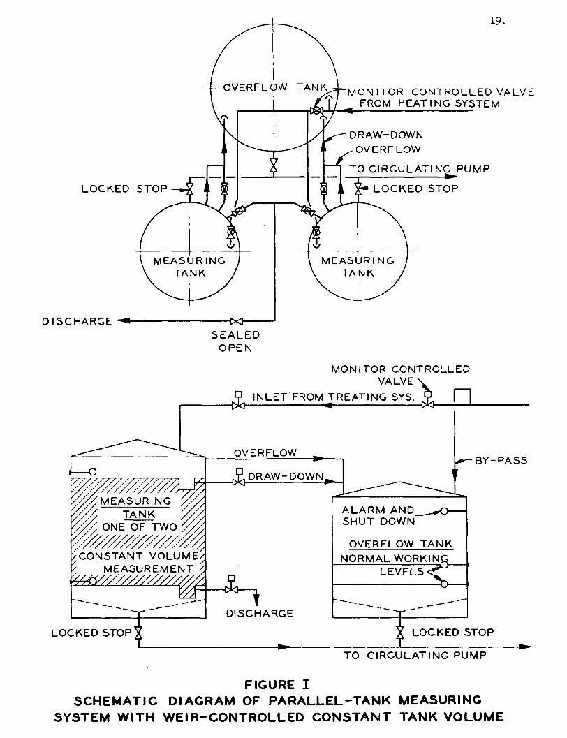
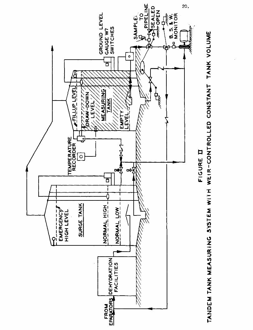
1. I n i t i a l Systems. The i n i t i a l LACT systems were developed arounc the
use of the conventional lease tankage primarily to duplicate as closely as possi
ble the then accepted requirements for custody transfer measurements and secondly
to permit the use of LACT with a minimum of additional expense for the great num
ber of lease tanks in existence. These early LACT systems employed floats or
weirs to control the fixed volumes to be transferred each dump (see Fig. I and
Fig. I I ) . Measuring tanks of this design are s t i l l acceptable and sometimes used
where conventional stock tanks can be economically converted.
2. Present Systems. From these systems evolved the idea of the present
measuring tanks which now fi n d general industry acceptance. The tanks d i f f e r
LOCKED STOP
DISCHARGE
19.
MONITOR CONTROLLED VALVE FROM HEATING SYSTEM
DRAW-DOWN OVERFLOW
TO CIRCULATING PUMP
LOCKED STOP
SEALED OPEN
/CONSTANT VOLUME/ ' MEASUREMENT '
LOCKED STOP t
MONITOR CONTROLLED VALVE
P INLET FROM TREATING SYS. -Okj ««
OVERFLOW
DRAW-DOWN.
BY-PASS
1 DISCHARGE
A L A R M AND SHUT DOWN
OVERFLOW TANK NORMAL WORKIN
LEVELS
LOCKED STOP
TO CIRCULATING PUMP
FIGURE I S C H E M A T I C DIAGRAM OF P A R A L L E L - T A N K MEASURING
S Y S T E M WITH W E I R - C O N T R O L L E D C O N S T A N T TANK V O L U M E
21.
from the adaptation of the conventional tank in that control of the lower l i q u i d
level is so positioned as to provide complete drainage of the tank each measuring
cycle, thus eliminating the possibility of bottom accumulations within the measur
ing vessel. These tanks are designed in the following three general forms and are
available from many manufacturers:
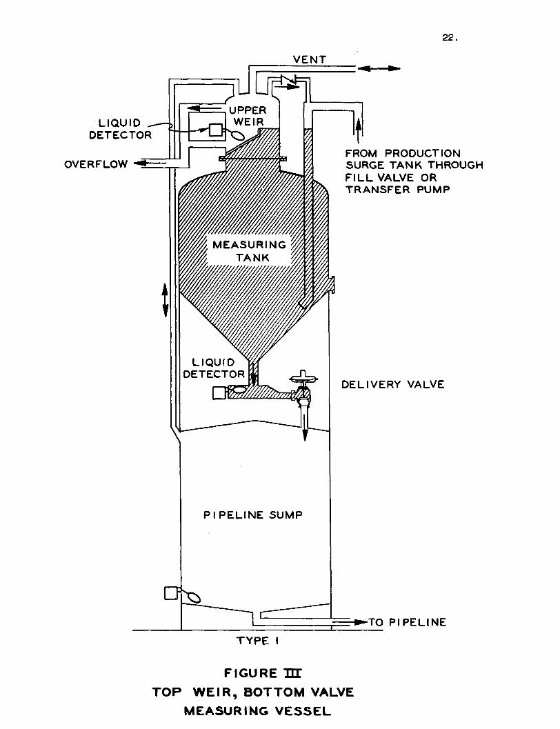
Measuring Vessel Having Top Weir and Bottom Valve (Fig. I l l )
1. Maimer of Operation. This vessel is usually an upright cylindrical ves
sel with a cone top and cone bottom, a semieliptical head and bottom, or any combi
nation of these two configurations. The top section consists of a weir enclosed
by a dome to act as an overflow chamber for the weir. A level detector is located
in the overflow section at least an inch below the weir level so that the measuring
section must f i l l with l i q u i d and overflow the weir before the level detector comes
into action, stopping the f i l l cycle. Thus, a f u l l measuring chamber is assured
each time. A delivery valve in the lower reduced section establishes the exact
point of the lower l i q u i d level of the measured volume and is so positioned as to
provide complete drainage of the vessel. A level detector or liquid-sensing
device is situated i n the lower portion of the measuring chamber and controls the
action of the delivery valve so that complete delivery is made each dump. The
control system interlocks the upper level-sensing device and the lower level-
sensing device so that a constant gross volume of o i l i s delivered during each
cycle. The delivery valve represents the point at which the transfer of custody
occurs.
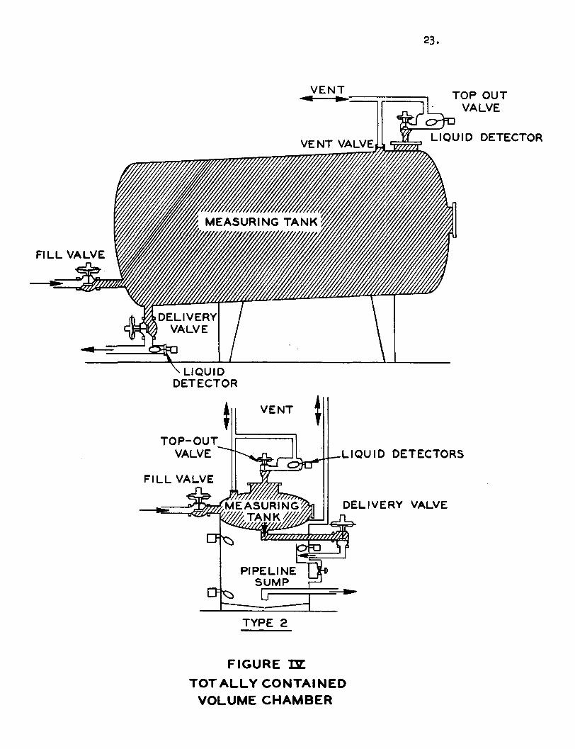
The Totally Contained Volume Chamber (Fig. IV)-
1. Manner of Operation. This vessel takes the form of a vertical or hori
zontal cylindrical tank with top and bottom reduced in cross section. This vessel
contains a valve i n each reduced section with level-sensing devices external to
22.
V E N T
T Y P E I
FIGURE TJX TOP W E I R , BOTTOM VALVE
MEASURING V E S S E L
23.
TYPE 2
FIGURE m T O T A L L Y CONTAINED
VOLUME CHAMBER
24.
the vessel to control the action of the valves. A valve is also provided in the
f i l l leg. The exact metered volume is contained between the three valves. The
delivery valve is the pqint at which the transfer of custody occurs.
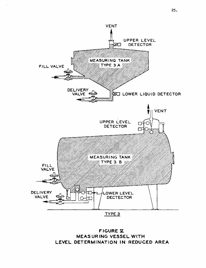
Measuring Vessel Having Level Controls within a Reduced Area (Fig. V)
1. Types. Vessels with reduced-area level control sections are of two
general forms:
a. Vertical Vessel Type. Vertical cylindrical vessels with conical
top and bottom having a reduced area and level control in the
center of the upper cone and a delivery valve in the outlet of
the lower section. A fl o a t in the bottom section serves only
as valve control. The contained volume of this tank is deter
mined by level-sensing device in the top and the face of the
delivery valve in the bottom.
b. Horizontal Vessel. A horizontal cylindrical vessel with reauced-
area sections at top and bottom with level controls in each
reduced-area section. The horizontal cylindrical vessel is
slaj»H5(S5rIi#rf:Iy sa&JCs constructed with the upper reduced
area on the highest end of the vesfel while the lower reduced ' »i ... .
afgpg^ Ideated on the lowest end of tr^ vj#eel. Bii» er<MTides
good drainage and prevent* any gas trap. Contained volume of
this tank is determined entirely by the level-sens iag devices.
Transfer of custody oe*urs at the^ieliv^ry valve in the lover I
section. *—
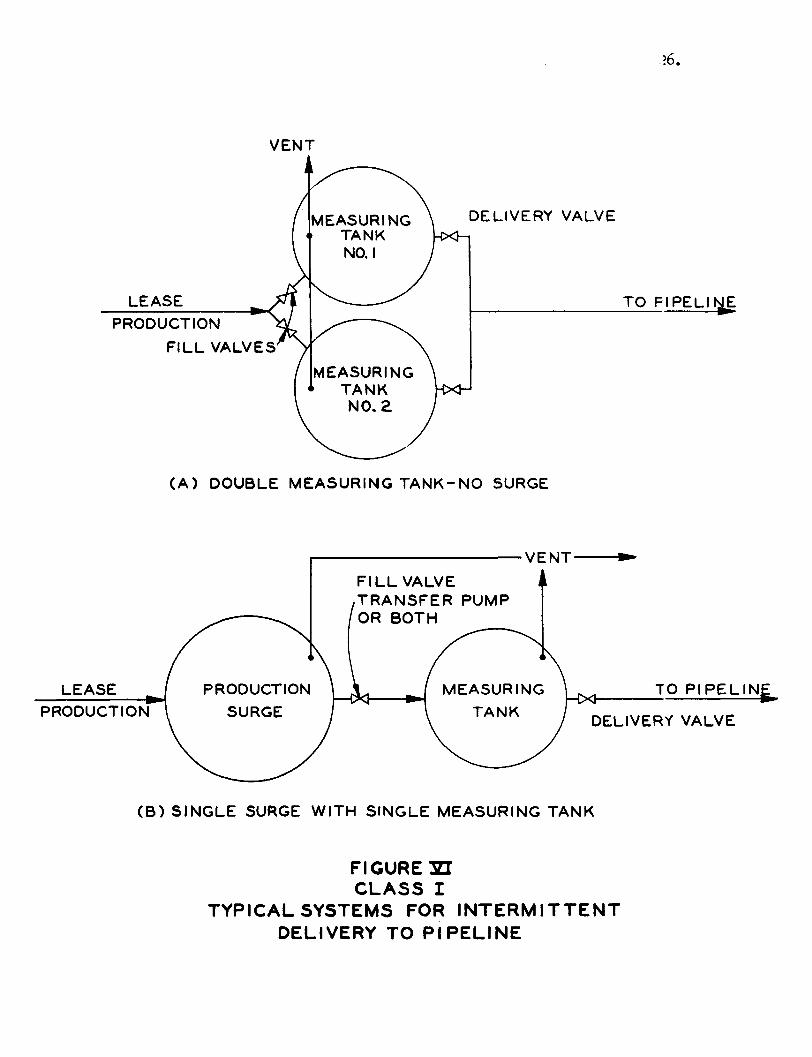
TANK ARRANGEMENTS
1. Classification. Measuring-tank systems may be placed in two general
classifications. Class 1 systems (Fig. VI) are intermittent-delivery systems
and Class 2 systems (Fig. VII) are continuous-delivery systems, as established
25.
VENT
TYPE 3
F I G U R E E. MEAS UR ING V E S S E L WITH
L E V E L DETERMINATION IN R E D U C E D A R E A
16.
VENT F ILL VALVE
LEASE PRODUCTION
(B) SINGLE SURGE WITH SINGLE MEASURING TANK
FIGURE m C L A S S I
TYPICAL SYSTEMS FOR INTERMITTENT DELIVERY TO P I P E L I N E
LEASE PRODUCTION
- • V E N T 27-
TO P IPEL I NT
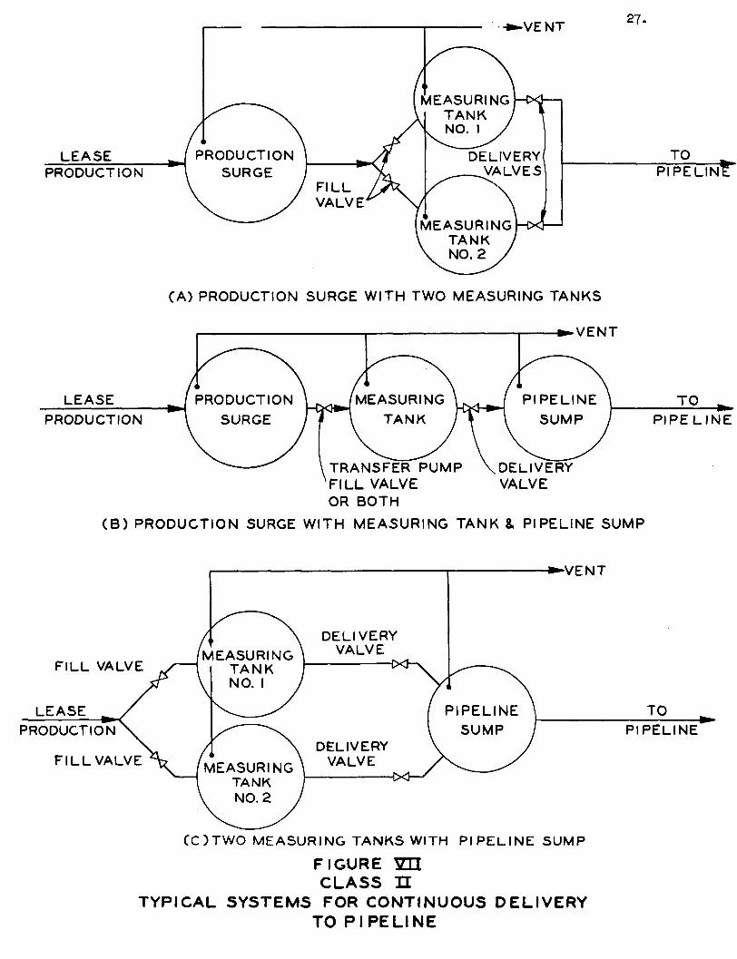
CA) PRODUCTION SURGE WITH TWO MEASURING TANKS
LEASE
PRODUCTION
\ TRANSFER PUMP F I L L VALVE OR BOTH
VENT
DELIVERY VALVE
TO
PIPE L I N E
( B ) PRODUCTION SURGE WITH MEASURING TANK & PIPELINE SUMP
•VENT
C O T W O MEASURING TANKS WITH P I P E L I N E SUMP
FIGURE YD. C L A S S n
T Y P I C A L S Y S T E M S FOR CONTINUOUS D E L I V E R Y TO P I P E L I N E
28,
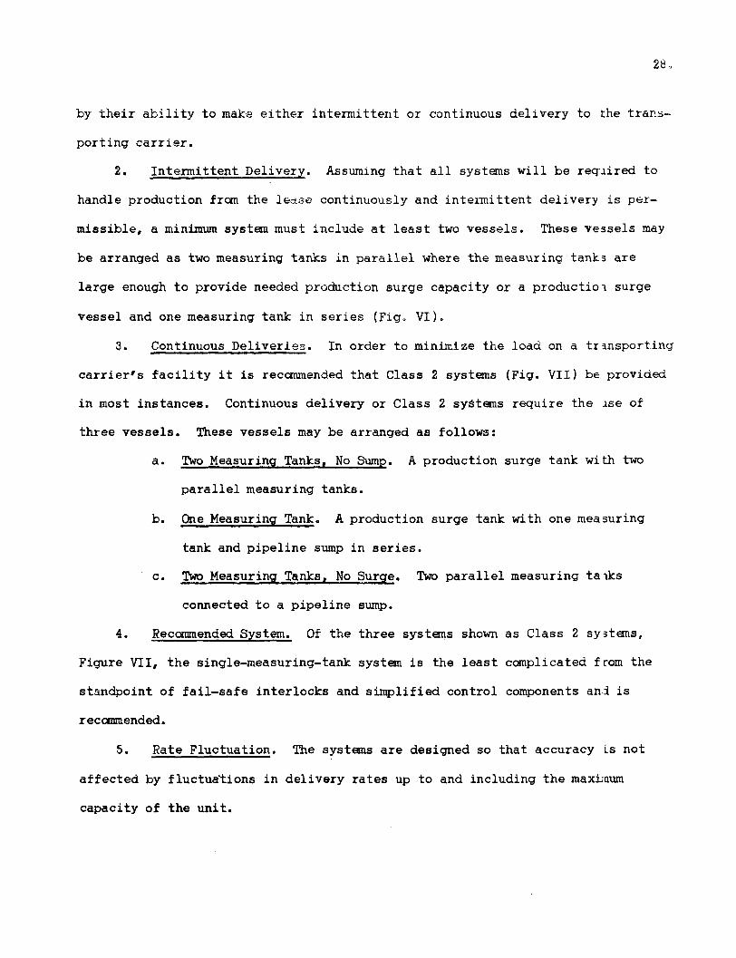
by their a b i l i t y to make either intermittent or continuous delivery to the trans
porting carrier.
2. Intermittent Delivery. Assuming that a l l systems w i l l be required to
handle production from the lease continuously and intermittent delivery is per
missible, a minimum system must include at least two vessels. These vessels may
be arranged as two measuring tanks in parallel where the measuring tanks are
large enough to provide needed production surge capacity or a productiot surge
vessel and one measuring tank in series (Fig. VI).
3. Continuous Deliveries. In order to minimize the load on a transporting
carrier's f a c i l i t y i t is recommended that Class 2 systems (Fig. VII) be provided
in most instances. Continuous delivery or Class 2 systems require the ase of
three vessels. These vessels may be arranged as follows:
a. Two Measuring Tanks, No Sump. A production surge tank with two
parallel measuring tanks.
b. One Measuring Tank. A production surge tank with one measuring
tank and pipeline sump in series.
c. Two Measuring Tanks, No Surge. Two parallel measuring taiks
connected to a pipeline sump.
4. Recommended System. Of the three systems shown as Class 2 systems,
Figure V I I , the single-measuring-tank system is the least complicated from the
standpoint of fail-safe interlocks and simplified control components and is
r ec ommended.
5. Rate Fluctuation. The systems are designed so that accuracy is not
affected by fluctuations in delivery rates up to and including the maximum
capacity of the unit.
29 =
SPECIAL REQUIREMENTS
1. General. Measuring tanks are emptied with no means provided to wipe
the interior surfaces clean. Therefore, volume cannot change due to surface
wear. The problem of incrustation and surface clingage must be dealt with in
some manner.
2. Incrustation. Incrustation may be controlled and in most cases has
been successfully prevented by applying to the interior surface of the measuring
tank a baked-on phenolic coating, a catalytically set modified phenolic or epoxy
coating, or ceramic coatings. Other materials w i l l be acceptable when so proven.
3. Clingage. The effect of clingage may be determined by actual measure
ment of the run down volume in a measuring tank after the delivery valve is closed.
Measurement should be made at normal operating temperatures and sufficient time
allowed to satisfy the parties concerned. Correction for clingage shall be
applied to the vessel calibration factor.
4* Valves. Valves used to control l i q u i d to or from a measuring tank must
be constructed with soft seats. The valves must be checked periodically to assure
that the seat closes bubble tight. A l l valves which are used to contain the pre
determined volume in a measuring tank should be either normally closed or adequately
interlocked to prevent mismeasurement in the event of power failure or instrument
gas-supply failure. Limit switches or p i l o t control should be properly applied to
these valves in order to provide such interlock control. In the measuring tank
described as Type 1, Figure I I I , which uses a transfer pump to f i l l , the inter
lock must be provided between the delivery valve and the transfer pump power
ci r c u i t .
5. Level Detectors. Level detectors need be only as sensitive as the par
ticular system requires, but i n a l l cases must be reliable. Level detectors which

30.
control multiple c i r c u i t s i n the control and interl o c k system must be equipped
with switches or p i l o t s properly designed so that mismeasurement does not cccur,
even though maladjustment may develop.
6. Calibrated Volume. A l l valves which confine a measured volume ard a l l
l e v e l detectors which are wi t h i n the measured confines of the vessel should be
attached with a type coupling which w i l l allow removal and replacement without
a l t e r i n g the calibrated volume of the measuring vessel. Either shop or f i e l d
c a l i b r a t i o n i s acceptable.
DATA HANDLING
1. General. The ultimate i n automatic volume measurement i s the adaptation
of f u l l y BS&W compensated and temperature-compensated data readout. Temperature-
compensated data readout i s presently available to a l l measuring tank systems.
Temperature averaging, BS&W averaging and gra v i t y averaging equipment i s currently
available to measuring tank systems which when applied to a gross volume counter
provide complete data readout and may eliminate the need f o r a proportiona . mechani
cal sampler. Many systems currently i n operation employ the individual teiperature
recorded system w i t h a gross dump counter. The l a t t e r systems require manially
calculated volume-temperature corrections, but may be found adequate i n many cases.
A pressure-head recorder i s very desirable as a gross volume check on the measure
ment cycle or i n the event a mismeasurement occurs.
RECALIBRATION OF VESSELS AND COMPONENTS
1. Inspection and Volume Recalibration. A means of inspection should be pro
vided on each measuring vessel. Vessels should be inspected p e r i o d i c a l l y . Recali-
bration i s not necessary unless inspection indicates that the volume obvicasly has
been changed. Recalibration may be requested by either party.
2. Temperature Instruments Calibration. Temperature instruments shall be
recalibrated at mutually agreed intervals using a c e r t i f i e d t e s t thermometer to
31.
correlate two or more temperatures within the normal operating range. Correlation
should check within 1% of the maximum range of the instrument. This calibration
must be performed with the instrument temperature element and the certified test
thermometer immersed in a temperature controlled liquid bath. Temperature instru
ments should be checked for proper adjustment at frequent intervals by simply com
paring the recorder temperature reading with that of an approved ASTM or API
thermometer during normal operation.
MINIMUM MEASURING TANK VOLUME
1. Maximum Capacity. The maximum capacity of the various measuring tank
systems will be governed by the size of the measuring tank or tanks, the speed of
response in the temperature system, the time required for proper elimination of
entrained gas and adequate draindown. Care should be exercised in sizing the unit
so that the time elapsed between the f i l l and dump cycle is sufficient to obtain
a stabilized temperature reading.
2. Delivery Rate. The measuring tank system possesses the inherent ability
to deliver at any rate up to the maximum capacity as determined above. This rate
may be controlled throughout the capacity range by the ability of the transporting
carrier to receive oi l .
VENT SYSTEM
Vent Lines. Vent lines in the system should be of adequate size to pre
vent abnormal buildup of pressure or vacuum on any vessel in the system during any
sequence in the operating cycle. Adequate protection against liquid movement through
the vent system must be provided.
SECTION I I I - METER SYSTEMS - POSITIVE DISPLACEMENT METERING
INTRODUCTION
1. The purpose of this section is to outline and recommend acceptable and
practical methods of obtaining reliable and accurate measurements of leetse runs by
means of the positive displacement meter system. The PD meter is a par": of a sys
tem of devices arranged in a manner such that custody transfer of lease runs or
other stocks can be automatically and continuously made while unattended.
2. This section discusses procedures and practices for meter selection,
installation, operation, maintenance and calibration which are considered essen
t i a l to accomplish the measuring accuracy and r e l i a b i l i t y required.
8. I t is recommended that API Standard 1101 be used where portions of that
standard are applicable. This section is not intended as an independent ef f o r t
to standardize PD metering of crude o i l but more as an adaptation of PD metering
as one of the acceptable methods of obtaining the volume measurement fo:: Lease
Automatic Custody Transfer Service.
DEFINITION OF TERMS
1. Manner of Operation. Positive displacement meters are meters which mea
sure a f l u i d by separating the f l u i d into segments and counting these segments.
These meters displace or carry through their measuring elements a fixed quantity
plus the slippage for each stroke, revolution or cycle of the moving elements.
2. Standard 1101. The terms pertaining to PD metering which are in common
usage within the petroleum industry have been set out in the Introduction of API
Standard 1101 and w i l l have the same meaning and significance when used herein.
33.
SELECTION OF POSITIVE DISPLACEMENT METERS
1. Data Needed. Each location and application of meters w i l l require a
certain amount of individual consideration. I t is recommended that the following
pertinent data be defined and analyzed before selecting a meter and planning an
installation for a particular service:
a. Range. Range of operating rates of flow.
b. Pressure. Maximum pressure which meter w i l l have to withstand.
c. Liquid Characteristics. Type of l i q u i d or liquids meter w i l l
measure including viscosity, corrosiveness, RVP and API gravity^
d. Temperature. Ambient and f l u i d temperature range under which meter
w i l l operate.
e. Temperature Compensation. The applicability of automatic tempera
ture compensation.
f. Abrasive Materials. The amount of abrasive and size of particles
and water which w i l l ultimately reach the meter.
g. Register. Type of register or printer desired.
2. Selection. After analysis of the foregoing data, the selection should
be in accordance with the manufacturer's recommendations for a meter f u l f i l l i n g
the requirements.
3. Capacities. The meter manufacturers have established recommended flow
rates for various sizes of meters of their manufacture and should be consulted
for their specific recommendations.
INSTALLATION OF POSITIVE DISPLACEMENT METER SYSTEMS
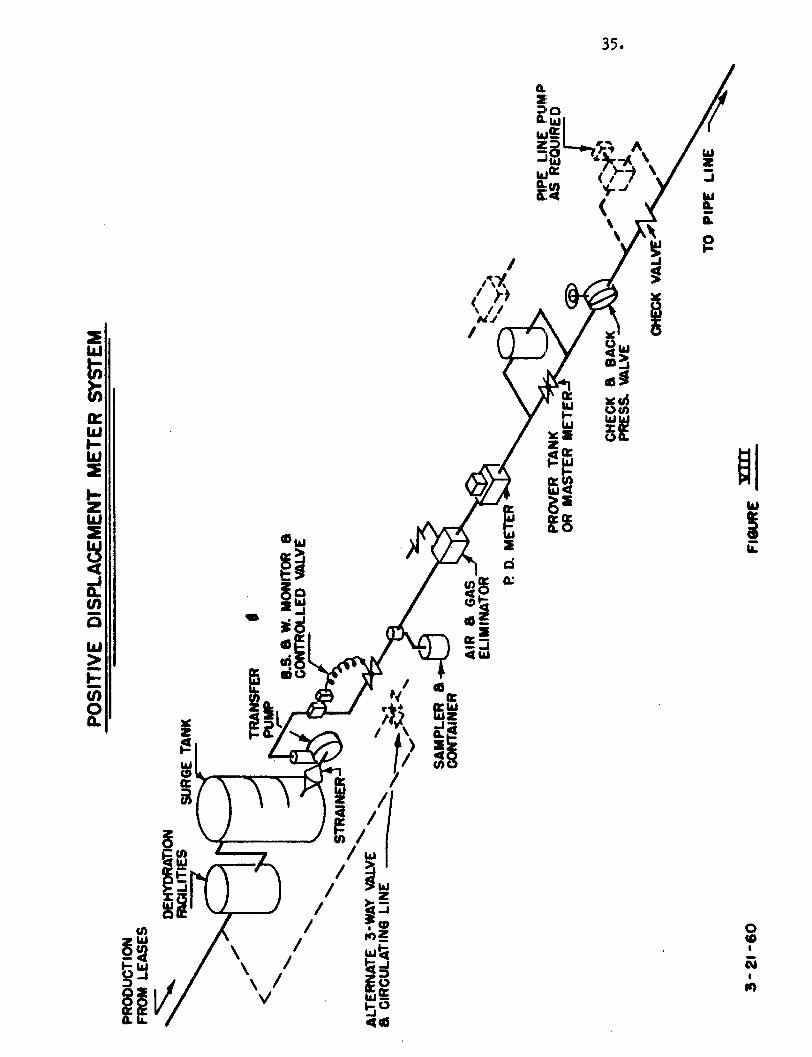
1. General Arrangement. A recommended arrangement of equipment for auto
matically measuring lease runs by the positive displacement meter method is shown
34.
in Fig. VIII. The location of each item of equipment should be such tha-: i t will
properly perform the function for which i t is intended depending on existing
circumstances.
The schematic arrangement shown will provide satisfactory results
under most conditions and is intended to be used only as a guide for meter sys
tems installations. Under certain circumstances the arrangement of equipment
should be altered to meet the requirements. For example, the choice of a three-
way or a conventional valve to control flow to the pipeline will influence the
location and arrangement of other items of equipment. The location of the moni
tor sensing element which detects nonmerchantable liquid must be such that i t
will be in the stream regardless of the type control valve selected. The sampler
should be located in a position to adequately sample the custody transfer stream
without influencing the accuracy of the meter measurement.
2. Specific Requirements. Some important considerations regarding meter
installations are as follows:
a. Air Elimination. The installation should be such that aii or
gases will not be introduced into the system through holes,
leaky valves, packing glands of pump shafts or connecting lines.
In a l l installations which are conducive to the passage of air
or gas, adequate air elimination equipment should be installed
ahead of the meter. Such equipment shall in no case be oi
smaller rated maximum capacity than that of the pump or feed
lines and shall provide complete air elimination, assuring a
liquid-filled meter. Vapor outlet lines from air eliminators
should be installed for suitable disposal of the vapor.
35.
b. Flow Reversal. The piping system should be arranged to prevent
reversal of flow of liquid through the meter.
c. Vaporizing of Stream. Any condition which tends to increase the
turbulence of the system should be designed to'mentoaeae the pos
sibility of vaporizing the stream.
d. Surges. Meters subjected to pressure pulsation or surges should
be adequately protected by surge tanks, expansion chambers or
similar devices; and no meter shall be subjected to shock pres
sures which are greater than its maximum rated working pressure.
e. Proving. Meter installations should be equipped with either
manual or automatic means to permit proving at normal operating
conditions.
f. Accuracy Range. All meter installations should be designed so
that the flow rate through every meter is held between the maxi
mum and minimum limits within which the desired accuracy is
obtainable.
g. Bypasses. Any unmetered bypass around a meter or battery of
meters shall be provided with a suitable means to prevent
undetected flow around the meter.
3. Gross Check. A method should be provided for a gross check on th*
meter system to make certain that a l l liquid that passes the meter is indicated
on the counter or printer. Some of the methods in use are:
a. Two meters in series.
b. Spot-gauging in tanks or comparison with production
testing facilities.
c. Pulse counters on the meter.
37.
d. Use of temperature or pressure recording instruments to
detect flow through the meter.
METER PROVING FACILITIES AND PROCEDURES
1. Proving Fac i l i t i e s . Meter accuracy is dependent on the proving f a c i l i
ties provided,and the type of f a c i l i t i e s required for accurate proving var>'
several factors such as characteristics of the f l u i d , pressure or
available, flow rates, and ambient temperature. Once adeq.v' -o-c° -
are provided, then accurate proving procedures mxfj*'' "jd£ \\&^
2. Methods. Methods of proving met'"' <. e ^ < ^
:3rov«jr Tanks as outlined in API F>- & ^ 0^v ^ l
t r a n j s f ^ Installation she**'' ^ e $9°° eVe'
methods, shoirld **' ^ ^ ^ . A e * /
3 . ^ e ^ 0 ^ ^ ^ d - 0 ^ o 0 ^ e -portion of the Surge Tank equipped
X & ' o t ^ ^ x ^ 0 \ p ^ thermometers and calibrated by the water
- ^ s - -as a prover tank i f agreeable to the parties concerned. The
9 >
% ' . ^ K P ^ Q - C ^\e^° ,^rse strapping method outlined in applicable API
m. ^ r i t y of the calibrated section of such prover should be ten times the
max^turtTvolume delivered per minute by the largest meter to be proved. "The distance
between the opening and closing levels and the provision for determining the opening
and closing readings should be sufficient to detect variations of .057».
4. Proving Frequency. The frequency of calibration should be determined
by meter-factor behavior and the degree of accuracy required. I t is recommended
that PD meters be calibrated at least once per month.
5. Calibration' Records. The calibration, record for each meter should be
kept on f i l e as long as the meter ticket to which i t applied. A copy of each
o f f i c i a l calibration record should be supplied by~Ajis metier www to each party
concerned.
38.
fc. Meter Factor Record. The ticket on which the metered quantity is
reported should have space provided for the meter factor and the number of the
calibration record which supports the meter factor on the ticket.
METER SYSTEM OPERATION
1. Procedures. To insure desired accuracy in the metered measurement of
liquid hydrocarbons, i t is essential that associated meter operating procedures
and inter-party understandings and relationships in connection with metered trans
actions be understood and accepted by al l concerned.
2. Degree of Accuracy. The degree of accuracy desired in each installation
is the governing factor in determining the extent of operating control. As used
in connection with Lease Automatic Custody Transfer Service, the greatest degree
of meter accuracy should be sought. For successful meter operation the proving
system shall provide complete flexibility, and in a l l cases the proving of meters
should as nearly as possible simulate actual operating conditions.
3. Temperature Determination. The accurate operation of meters necessi
tates very careful handling of the various phases of metering which are affected
by temperature. Obviously, precision temperature measurement is a prerequisite
of precision metering, whether the temperature is determined by an independent
thermometer or indirectly by means of an automatic temperature compensator. Pro
viding a reliable automatic temperature compensating device can be procured for
the meter used, this method of obtaining volumes at the base temperature of 60°F
is more desirable than using some temperature indicating or recording device and
then mathematically reducing indicated volumes to 60° F. In either case the
coefficient of expansion used must be consistent with agreements between the
parties concerned.
39.
4. Operation and Maintenance. There are many details in the successful
and accurate operation of displacement meters in the f i e l d which cannot easily
be described in a text or manual but which are essential to good metering.
They are items which the meter operator must acquire through training and
experience in the f i e l d . They include such things as quality meter repair
and maintenance work, elimination of human errors, the detection of leaking
valves, recognition of a i r or gas troubles, flow rates, meter reading, tempera
ture reading, etc. Operating practices outlined in API Standard 1101 are recom
mended as a guide for good metering results.
5. Basic Requirements. Basically, a PD meter system should be designed
and operated such that i t complies with requirements of paragraph 2, Section I ,
page 5.
6. Components. A suggested combination of major items of equipment to
provide automatic measurement by the positive displacement, meter method is shown
in Figure V I I I . The system, as shown, has no provision for automatically han
dling nonmerchantable l i q u i d when i t reaches the monitor and, therefore, requires
manual attention under such circumstances. A system employing a recirculating
system including a diverting valve by which nonmerchantable l i q u i d can be
treated is acceptable providing i t is designed properly.
40.
7. Recommended Sequence of Operation. Recommended sequence of operation
will vary slightly depending on the type of pipe line facility connected and the
operating schedule of the pipe line. Details should be worked out for each instal
lation; however, the following is recommended as a guide for a system which does
not make use of recirculating arrangement. Recommended sequence for:
a. Kormal Delivery to a Gravity Flow Pipe Line - Nonscheduled Operation.
1. When the liquid level in the surge tank reaches normal high
working level, the transfer pump starts and the controlled
valve opens to the pipeline admitting flow through the meter.
2. When the valve reaches its open-to-pipeline position, the
automatic sampler is energized and begins sampling.
3. Under normal conditions, delivery to the pipeline continues
until the liquid level reaches the normal low level position.
4. Then, the controlled valve closes the pipeline outlet,, the
transfer pump stops and the automatic sampler is de-energized.
Non-Merchantable Oil Interruption. After the delivery to the pipe
line has begun, should nonmerchantable oil flow continuously past
the BS&W monitor for a predetermined time interval, the transfer
pump is automatically stopped and:
1. The valve closes, stopping flow to the pipeline.
2. The automatic sampler is de-energized.
3. The controls should lock out the transfer equipment until
the nonmerchantable liquid has been treated out to meet
specifications.
b. Normal Delivery to a Pressurized Pipeline - Nonscheduled Operation.
1. When the liquid level in the surge tank reaches normal high
working level, the transfer pump starts, the valve opens to
the pipeline admitting flow to the meter.
41 =
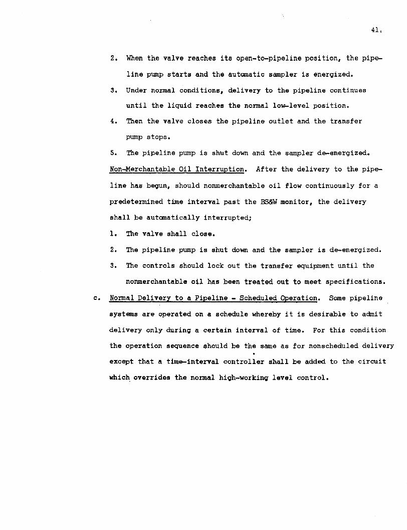
2. When the valve reaches i t s open-to-pipeline position, the pipe
line pump starts and the automatic sampler is energized.
3. Under normal conditions, delivery to the pipeline continues
u n t i l the l i q u i d reaches the normal low-level position.
4. Then the valve closes the pipeline outlet and the transfer
pump stops.
5. The pipeline pump is shut down and the sampler de-energized.
Non-Merchantable Oil Interruption. After the delivery to the pipe
line has begun, should nonmerchantable o i l flow continuously for a
predetermined time interval past the BS&W monitor, the delivery
shall be automatically interrupted;
1. The valve shall close.
2. The pipeline pump is shut down and the sampler is de-energized.
3. The controls should lock out the transfer equipment u n t i l the
nonmerchantable o i l has been treated out to meet specifications.
c. Normal Delivery to a Pipeline - Scheduled Operation. Some pipeline
systems are operated on a schedule whereby i t is desirable to admit
delivery only during a certain interval of time. For this condition
the operation sequence should be the same as for nonscheduled delivery m
except that a time-interval controller shall be added to the c i r c u i t
which overrides the normal high-working level control.


![4 - Engineering Bureau - ADMINISTRATIVE APPLICATION …ocdimage.emnrd.state.nm.us/imaging/filestore/SantaFeAdmin/AO/... · [3] [A] Check One Only for [B] or [C] ... (Start/Resume)](https://img.pdfslide.net/doc/110x75/5c8ce0e009d3f236358c9934/4-engineering-bureau-administrative-application-3-a-check-one-only-for.jpg)

![ays If - ocdimage.emnrd.state.nm.usocdimage.emnrd.state.nm.us/Imaging/FileStore/santafeadmin/ao/30… · [D] Other: Specify POOL:CUU0PA BLOFF, NOTIFICATIONREQUIRED TO: - Check Those](https://img.pdfslide.net/doc/110x75/601bea9bb80c5043ab6ae9d3/ays-if-d-other-specify-poolcuu0pa-bloff-notificationrequired-to-check.jpg)


![ADMINISTRATIVE APPLICATION COVERSHEETocdimage.emnrd.state.nm.us/imaging/Filestore/SantaFeAdmin/AO/2253… · [DD-Directional Drilling] [SD-Simultaneous Dedication] [DHC-Downhole Commingling]](https://img.pdfslide.net/doc/110x75/5ac20e7f7f8b9a213f8dd162/administrative-application-dd-directional-drilling-sd-simultaneous-dedication.jpg)