Embed Size (px)
DESCRIPTION
محاضرات د. فاروق القاضي
Citation preview

For Lectures, assignments and
PDFsVisit Dr. Farouk’s Official Page
www.facebook.com/dr.farouk.elkadi

Braced Cuts and Cofferdams
Prepared By:
Prof. Dr. Ing. Farouk El-Kadi
Professor of Geotechincal Engineering
Faculty of Engineering
Ain Shams University
Shorouk AcademyFaculty of EngineeringCivil Engineering DepartmentCourse : Foundation Engineering 2 – Fourth Year CivilYear : 2012 - 2013Version : 00

Dams and Levees• Content
1.1 Introduction
1.2 Dams
1.3 Hydrology and Hydraulics
1.4 Types of Dams
1.4.1 Concrete Dams
1.4.2 Earth Dams
1.4.3 Rock fill Dams
1.4.4 Roller compacted concrete Dams
1.5 Geotechnical analysis and design of Earth Dams
1.5.1 Seepage
1.5.2 Slope stability
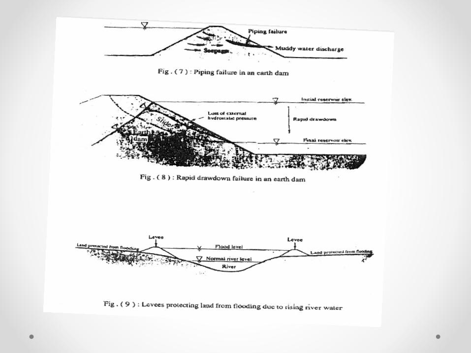
1.6 Lessons from Dams failures
1.7 Levees
1.8 Summary


Brace Excavation

(2) Braced CutsContent
1) Construction and construction elements.
2) Loading (Earth pressure).
3) Design of structural elements.
4) Check to avoid heave in cohesive soil.
5) Stability of the bottom of cut in sand.

1- Construction and construction elements
Braced cuts
.Braced Cutالشكل يوضح نموذج للمكونات األساسية للعناصر اإلنشائية التي تكون
:وهى تتلخص في اآلتي
a- Vertical wall soldier beam and lagging as sheet pile.
b- Wale.
c- Strut.

(b) Braced cut using soldier beams

2- Loading (earth pressure)
(Braced Cut)
على الحائط الساند للحفر هو الحمل ( earth pressure)ضغط التراب •
.الرئيسي المؤثر
السابق ( earth pressure)حتى يمكن استخدام معادالت ضغط التراب •
:شرحها يجب أن يتحقق اآلتي
• No deformation (Rigid wall).
• Translation or rotation for the supporting wall.
ية لضغط لذلك بناء على القياسات الحقلية والمعملية تم الوصول إلى قيم تقريب•
(. انظر الشكل( )Braced Cut)التراب يمكن استخدامها في تصميم

2.1) Apparent pressure diagrams for
sand, firm clay and soft to medium clay

• Terzaghi and peck method based on the following :
•
• Excavation ≥ 6.0m
• Artificial loading diagram is used for determining strut loads
• Water table is below bottom of excavation
• Pore pressure is not considered .
• A stability expression (N) has been developed to indicate
• the performance of excavation in clay .
•
• 𝑁= γ 𝐻
𝐶(1)
•
• Ground movement becomes significant if :
• 𝑁≥ 3 𝑜𝑟 (2)
•
• Failure is likely if:
• 𝑁≥ 6
•
• Terzaghi – Peck (1967) unit pressure for sand
•
• ρ = 0.65 Ka γ 𝐻
• Ka= tan2(45° − ∅/2)
•
• Tschabotariaff gives ( ρ ) as follows
• ρ =0.8 Ka γ 𝐻 cos 𝛿 (3)
Calculation of Earth Pressure

• For clay
• Terzaghi- Peck (soft- to- med.) Clays
• P= 1.0 Kа γH (4)
• Ka = 1-m 2𝑞𝑢
𝛾𝐻
• For N≥ 3-4 m=1.0
• m< 1.0 for normally loaded clay
• For stiff fissured clay
• P= 0.2-0.4γH (5)
• Tschebotarioff (stiff clay)
• P= 0.3γH (6)
• Med clay
• P=0.375γH (7)

2.2) Non- uniform soils2.2.1 Braced cut passes through layers of both sand and clay (see Fig
I). An equivalent value of cohesion Ce (Φ = 0 concept) is
determined using the following equation suggested by (Peck
1943).
H = total height of the cut.
= unit weight of sand.
Hs = height of the sand layer.
Ks = a lateral earth pressure coef. .
= angle of friction of sand.
qu = unconfined compressive strength of clay.
n' = a coef. Of progressive failure .
= saturated unit weight of clay layer.
With the values of and Ce the distribution of apparent earth pressure given in (Fig II )Can be used


2.2.2 Braced cut passes through a number of
clay layers (Fig III)
When the braced cut passes through a number of clay layers, the equivalent values of Ce and are determined from the following equations (Fig. III).
Where c1, c2,…cn are untrained cohesions of layer 1, 2…n and H1, H2, …Hn are the thicknesses of these layers (Fig. III).
Likewise,

3.0 Design of structural element (Braced Cut)
التصميم يعبر عن النظام االنشائى•.المستخدم
في حالة استخدام ستائر حديدية •(Sheet pile ) كحائط ساند للحفر
ب يتم وضع كمرات أفقية في المناسيلترتكز عليها ( Wales)المختلفة
لمؤثر وبالتالي ينتقل الحمل ا. الستائر)على الستائر إلى الكمرات
(Walesثم ينتقل الحمل من الكمرات(.Struts)إلى الركائز
.3)انظر الشكل I)
مطلوب وبالتالي تكون العناصر اإلنشائية ال:تصحيحها هي
الستائر (Sheet pile)-أ
الكمرات (Wales)-ب
الركائز (Struts)-ت

3.1) Design of sheet pile• The sheet pile will be designed/m.
• The reaction on the wales will be calculated.
• The sheet pile can be calculated as continuous beam
resting on the wales (A’,B’, C’, and D’) or to divide it in
three portions assuming two hinges one at B’ and one at
C’ (Fig 3. I).
• The wales must be designed as continues beam resting
on the struts.
• With the reaction in the struts, the struts can be designed
as compression member.
The moment in the strut due to its own weight and buckling must be taken into consideration.

3.2) Design of braced cut using soldier beams (Fig
3. I I)
كز على التي تقع وترت( سابقة التجهيز)ضغط التراب يؤثر مباشرة على البالطات •
وبالتالي يتم تصميمها في االتجاه األفقي ( Soldier beam)األعمدة الحديدية
(Simple beam.)
أماكن رد فعل هذه البالطات يقع على األعمدة الحديدية الراسية التي ترتكز في عدة•
وبالتالي يتم تصميمها في االتجاه الرأسي ( Wales)على الكمرات األفقية
(Continuous beam ) وتؤثر ردود أفعالها على(Struts.)
اتجة ككمرة أفقية تؤثر عليها قوى ضغط باإلضافة إلى العزوم النStrutsيتم تصميم •
. bucklingعن وزن الكمرة وتأثير

(Fig 3. I I) Braced cut using soldier beams

4- Check to avoid heave in cohesive soil• Braced cuts in clay become
unstable as a result of heaving of the bottom of the excavation.
• The failure surface for this case in a homogenous soil is given in (Fig 4. I).
• The ultimate bearing capacity at the base of a soil column (see Fig 4. I) with a width B’ can be given as:
The vertical load/unit area along plane (f i) is
The factor of safety against bottom heave is
• If F.S is less than 1.5, the sheet pile is driven deeper.

5.0 Stability of the bottom of cut in sand (Fig 5.I, 5.II)
• The bottom of a cut in sand is generally stable.
• When the water table is encountered, the bottom of the cut is stable as long as the water level inside the cut (excavation) is higher than the ground water table.
• In case dewatering is needed (Fig 5.I) the factor of safety, against piping should be checked.
• To check the factor of safety, draw flow nets and determine the max. exit gradient [imax(exit)]
(fig 5.II).
a = Length of the flow element.
Nd = number of drops.


• The factor of safety against piping can be
expressed as
F.S must be more than 1.5

Piping in Sand
To avoid piping (see seepage) the following charts are given (after NAVFAC DM-7 1971)
Fig(a): for determining sheeting pentration in granular soilFig (b) Piling penetration to prevent piping

Typical Single Wall Configuration of Retained Excavation
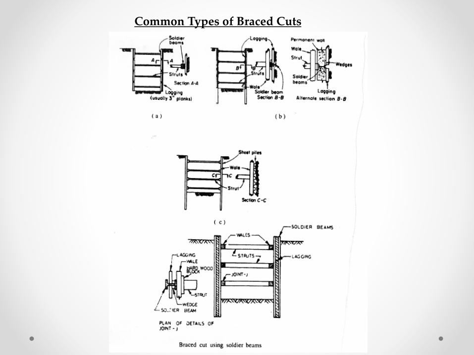
Common Types of Braced Cuts


Types of Coffer Dams• Earth cofferdam ( fig1)
• Well-adapted to depth of water up to 3ms
• Local soil – clay core or sheet pile
• Upstream slope covered with a rip rap
• 2- rock fill coffer dam ( fig2)
• usually provided with an impervious membrane of soil to reduce seepage
• 3- single – sheet pile coffer dam( fig3)
• Suitable for moderate – flow velocities of water depth of water about 4.0 ms
• depth of penetration in soil must be calculated
• 4-Double – wall sheet piling coffer dam ( fig4 )
• Double –wall sheet piling coffer dams higher than 2.5m should be strutted
• Sometimes inside berm is provided
• Fill material should have high coef. of friction
• It has the advantage of less leakage
• Suitable up to a height of 10 m

Coffer Dams Cont.5. Braced Coffer dams (Fig.5)
• Used to isolate a working area surrounded by water
• H must be higher than the flood level.
• Care must be taken during dewatering inside the coffer dam.
6. Cellular Coffer dam (Fig. 6,7)
Special shapes of sheet piles (Fig 8) to form a series of cells. There are 2 types
a. Diaphragm type (Fig. 6)
b. Circular Type (Fig.7)

Cellular Coffer damscontent
1.0 Diaphragm type.
2.0 Circular type.
2.1 Design of cellular coffer dams on rocks.
2.1.1 Location of saturation line for determining the weight of the soil in cell.
2.1.2 Average width.
2.1.3 Safety against sliding.
2.1.4 Safety against overturning.
2.1.5 Safety against slipping.
2.1.6 Safety against vertical shear.
2.1.7 Stability against bursting.
2.2 Design of cellular coffer dam on soil.

Cellular coffer dams• There are two types:
a- Diaphragm type (Fig I).
b- Circular type (Fig II).
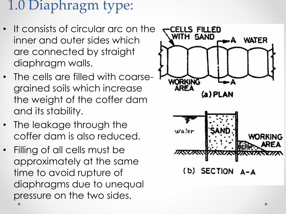
1.0 Diaphragm type:
• It consists of circular arc on the
inner and outer sides which
are connected by straight
diaphragm walls.
• The cells are filled with coarse-
grained soils which increase
the weight of the coffer dam
and its stability.
• The leakage through the
coffer dam is also reduced.
• Filling of all cells must be
approximately at the same
time to avoid rupture of
diaphragms due to unequal pressure on the two sides.

2.0 Circular type:
• It consists of large diameter main circular cells interconnected by arcs of smaller cells.
• The walls of connecting cells are perpendicular to the walls of the main circular cells of large diameter.
• The circular-type cellular coffer dams are self-sustaining, and therefore independent of the adjacent circular cells.
• Each cell can be filled independently.
• The stability of such cells is much greater as compared with that of the diaphragm type.
• Because the diameter of circular cells is limited by interlock tension, their ability to resist large lateral pressure due to high heads is limited.
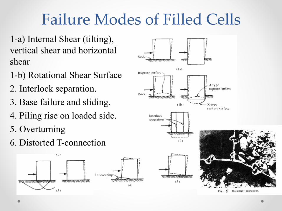
Failure Modes of Filled Cells1-a) Internal Shear (tilting),
vertical shear and horizontal
shear
1-b) Rotational Shear Surface
2. Interlock separation.
3. Base failure and sliding.
4. Piling rise on loaded side.
5. Overturning
6. Distorted T-connection

2.1 Design of cellular coffer dams on rock
2.1.1 Location of saturation line for determining the weight of soil in cell
• For determining the weight of the soil in the cell, it is required to locate the saturation line.
• The approximate location of the saturation line for different types of fill materials, as shown in fig.
• For a perfectly draining fill, the saturation line is shown in [fig. (a)].
• The lower half may be assumed saturated for analysis.
• For other type of fill, the saturation line at a slope of 2:1 is assumed [Fig. (b)].
• In case of a berm, the saturation line drops down to the top of the berm [Fig. (c)].
• For stability analysis, two extreme locations (marked 1 and 2) of saturation line should be investigated in this case.

2.1.2 Average width and estimation for the diameter of main cell
• The design of coffer dam is made for a
section 1m long and uniform, average
width.
• The average width is obtained by
equating the section modulus of the
equivalent rectangular section to the
actual section modulus.
• An approximate value of the average
width may, however, be obtained by
equating the equivalent rectangular
area to the actual area of the coffer
dam between center to center.

2.1.2 Average width and estimation for the diameter of main cell
cont.• The TVA engineers gave the following
relations for computing the average width.
• The above values of the average width are assumed in the preliminary analysis.
• The actual width to be provided is obtained after the stability analysis.
• The diameter "D" of the main cells is chosen depending upon the height "H" of the coffer dam. The diameter "D" of the main cells is given by
• The circular, cellular coffer dams are economical up to a total height "H" of 15 to 18m.

2.1.3 Safety against Sliding
• Coffer dam is subjected to horizontal
sliding force due to water pressure and
earth pressure.
• The sliding is resisted by the frictional
resistance at the base of the coffer dam.
• If berms are provided on the interior
side , the passive earth pressure also
helps in resisting the sliding.
• Thus the factor of safety against sliding
is as given in equation(1)

2.1.4 Safety against overturning
• Cofferdam should be safe against
failure due to over turning at toe (point
0).
• Neglecting the passive resistance, the
factor of safety against overturning is:
• The resultant of the forces must lie
within the middle third.

2.1.5 Safety against Slipping
• As the cell tends to tip over the toe, the fill material has tendency to run out.
• The piles on the water side creep up word as one unit.
• The piles on the dry side slip relative to each other.
• This behavior occurs because the frictional resistance between the fill and the piles on the water side is smaller than the frictional resistance along the interlock.
• On the water side, the force Pd pushes the pile against the fill.
• The frictional resistance between the pile and the fill equal µ’Pd.
• The factor of safety against slipping is:

• The value of friction coef. µ’ is
equal to tan δ.
• δ = angle of friction between the
fill and pile.
• The main width “b” required by
taking moments about the toe.
• If the sheet pile is embedded in
the rock for a substantial depth,
the effect of the active and
passive pressure should be
considered when summing up the
moments about the toe.
2.1.5 Continue Safety against Slipping

2.1.6 Safety Against vertical shear
• The cell may fail due to vertical shear developed along a plane through its center line.
• The max. shear “Q” is obtained by computing the max. bending moment acting on the cell, considering the cell as a vertical cantilever.
• The moment due to water pressure Pw
• Moment due to shearing force “Q”
• For stability, the shearing resistance developed must be greater than “Q”.
• The shearing resistance is equal to the sum of shearing resistance of soil (S1) and the resistance due to interlock (S2).

2.1.6.1 Shearing resistance of soil (S1)
2.1.6.2 Resistance due to interlock (S2)

2.1.7 Stability against bursting (interlock separation)
• The cell should be safe against bursting.• The stability against bursting depends upon interlock
stresses.• TVA engineers gave the following equation for the ring
tension (Tmax) for 90 - tees.
• p = horizontal pressure due to cell fill.
• H’= depth of soil up to that level.• θ = angle which the T makes with the axis.• L = one-half the distance between centers of main
cells.

2.2 Design of cellular dam on soil
The procedure for the design of a coffer dam embedded in deep soil is similar to that for a coffer dam resting rock.The following additional requirements must be satisfied.a- The sheet pile in sand must be driven to such a
depth that the bearing capacity at the level is greater than the vertical force acting on the pile.
b- A minimum factor of safety of 1.5 is generally recommended.
c- The maximum vertical force per unit length “Q” developed is equal to frictional resistance between the fill and the pile and is given by
Where H = height of cell above top of the stratum, Ka = coefficient of active earth pressure, δ = angle of friction between fill and pile, γ = unit weight of cell fill.
Where Qult = ultimate load capacity against bearing capacity failure.

2.2 Design of cellular dam on soil cont.d- If the coffer dam is embedded in clay,
the ultimate load capacity is given by
Qult = (5.7c)bWhere c = unit cohesione- The ultimate load capacity should be
greater than the fill load.f- The factor of safety is given by
g- A minimum factor of safety of 1.5 is recommended.
h- If the coffer dam is embedded in soft to medium clay, it should be safe against tilting caused by unequal settlement. The tilting can be estimated from the compressibility characteristics of the soil.
i- Cellular coffer dams on a deep sand deposit should have sufficient factor of safety against piping failure.

2.2 Design of cellular dam on soil cont.
•Fig. shows a coffer dam founded on deep sand bed. Water percolates under the base of coffer dam and rises up in front of the toe. The flow net can be drawn as shown. The flow lines are almost vertical in front of the toe. If the seepage pressure is equal to or greater than the submerged unit weight, quickly (boiling) conditions may develop.
The factor of safety against boiling is given by
Where i = hydraulic gradient at exit (=Δh/l), Δh = drop between last two equipotential lines, l = length of the last flow filed.•If the factor of safety is less than 1.5, a loaded filter is provided as shown to increase the downward force without increasing the seepage pressure.•The factor of safety can also be increased by reducing the gradient i by driving the sheet pile deeper or by reducing the effective head by permitting some water depth on the inner side.•The depth of the sheet pile below the ground surface is generally kept at least equal to two-thirds of the height of the coffer dam

Stresses Around Vertical Shafts and Tunnels
Stresses Around Vertical Shafts and Tunnels
• 3.1 Stresses around vertical shafts
• 3.1.1 Introduction
• 3.1.2 Cylinder Coordinates
• 3.1.2 Stresses in soil using cylinder coordinates
• 3.1.4 Calculation of Stress surrounding the shaft after
excavations
• 4.0 Tunnels

Stresses in Soil Vicinity of a vertical Shaft
ما هو الهدف من دراسة هذا الموضوع؟. 1
في كثير من المواقع الصحراوية يتم حفر آبار 1.1لسحب طلمباتدائرية بأعماق مختلفة حيث يتم وضع
. المياه
من سحبةالطلمبةنظراً إلى أن أقصى عمق للمياه تتمكن وقد الطلمبةم أما الطرد فيعتمد على قدرة 6في حدود
(.1شكل )م 60يصل إلى ما يزيد عن
وفي هذه الحالة يتم سند جوانب الحفر بحائط من المبانيعليه بأسماك مختلفة طبقاً للتصميم حيث أن الحائط تؤثر
قوى ضغط
Ring Compression

Stresses in Soil Vicinity of a vertical Shaft
خوازيق الحفر1.2
.من أكثر أنواعها شيوعاً اآلن هي خوازيق الحفر
م و 10سم كما تختلف األعماق بين 250و 40تختلف األقطار بين و كوبري بنها على النيل 1973كوبري دمياط على النيل عام )م 45
(جاري تنفيذه
قديما تم استخدام المواسير لسند جوانب الحفر بكامل العمق أما اآلن فيكتفي بسند الجزء العلوي من الخازوق(. بنوتوخوازيق )
م ويتم استخدام المياه داخل الحفر أو خليط من المياه 6في حدود لذلك نرى ضرورة توضيح مبادئ دراسة اإلجهادات ( والبنتونايت
. في التربة المجاورة للحفر بئر دائري

2.0 Cylindrical Coordinates
ة نظراً ألن الدراسة تتم بالنسب
لحفر دائري بأعماق مختلفة
لذلك نرى ضرورة الرجوع إلى
الـ إستخادم
حيث أن الدراسة تتم
على
Cylindrical Coordinates
Axis-symmetrical Case

3.0 Stresses at The Location of Shaft Before Excavation
The stresses at any point (Pr,z) before excavation of the shaft are given in fig.(3)We must notice that σz,σr,σϴ in this case are principale stresses. Then the shear stresses τrz are zero
𝜎𝑧𝑖 = 𝛾𝑧 1𝜎𝑟𝑖 = 𝑘0𝛾𝑍 2𝜎𝜃𝑖 = 𝑘0𝛾𝑍 3𝜏𝑟𝑖 = 𝑍𝑒𝑟𝑜 (4)

4.0 Stress in Soil after excavation
4.1 Using Lame’s theoryThe martial located within the boundaries of the proposed shaft can be replaced by an equivalent liquid of unit weight (γL) equal to (Koγ). The state of stress in soil will not change (Fig. 4) (γ = unit weight of soil)
𝑝 = 𝛾𝐿𝑧 = 𝑘0𝛾𝑧 5No effect on the stresses in the soil in the vicinity of shaft.The stresses due to equivalent liquid pressure using Lame’s formulae for thick cylinders, we get the following stresses at point (p) due to pressure of equivalent liquid
لحساب اإلجهادات في التربة المحيطة بالبئر بعد
نظريتان األولى نظرية إستخدامإتمام الحفر تم
والثانية نظرية
Shaft
Lame
Biot

4.0 Stress in Soil after excavation
4.2 Using Biot theoryo After the shaft has been excavated Fig 5,
the shear stresses and radial stresses on the interior surface are zero.
o The effect of excavation the shaft can be considered equivalent to that of pumping the liquid out of
a cylindrical hole whose dimensions are identical with those of the shaft (Biot 1935)o The stresses after excavation are:
𝜎𝑧 = 𝜎𝑧 𝑖 − 𝜎𝑧 𝑙 = 𝛾𝑍
𝜎𝑟 = 𝑘0𝛾𝑧 − 𝜎𝑟 𝐿 = 𝑘0𝛾𝑧 1 − 𝑟02
𝑟2
𝜎𝜃 = 𝜎𝜃 𝑖 − 𝜎𝜃 𝐿 = 𝑘0𝛾𝑧 1 + 𝑟02
𝑟2

Tunnels
Stresses in soil at any point P(r,z) before the excavation on the tunnel
𝜎𝑧𝑖 = 𝛾𝑧 1𝜎𝑟𝑖 = 𝑘0𝛾𝑍 2𝜎𝜃𝑖 = 𝑘0𝛾𝑍 3

Tunnels
Using the same method as in the case of shaft the stresses after excavation of tunnel will be:
𝜎𝑟 = 𝑘0𝛾𝑧 1 − 𝑟02
𝑟2
𝜎𝜃 = 𝑘0𝛾𝑧 1 + 𝑟02
𝑟2


![Lec 06 [1. reference types]](https://img.pdfslide.net/doc/110x75/5a65c4697f8b9a38648b4dab/lec-06-1-reference-types.jpg)