Embed Size (px)
DESCRIPTION
milling
Citation preview
Tool Design
Dr. Ramadan El gamsy Tool design
1-Cutting Tool Materials.2-Turning machining
3- Turning Form tools
Dr. Ramadan El gamsy Tool design
Cutting tool materials
• Selection of cutting tool materials is very important
• What properties should cutting tools have– Hardness at elevated temperatures– Toughness so that impact forces on the tool can
be taken– Wear resistance– Chemical stability
Dr. Ramadan El gamsy Tool design
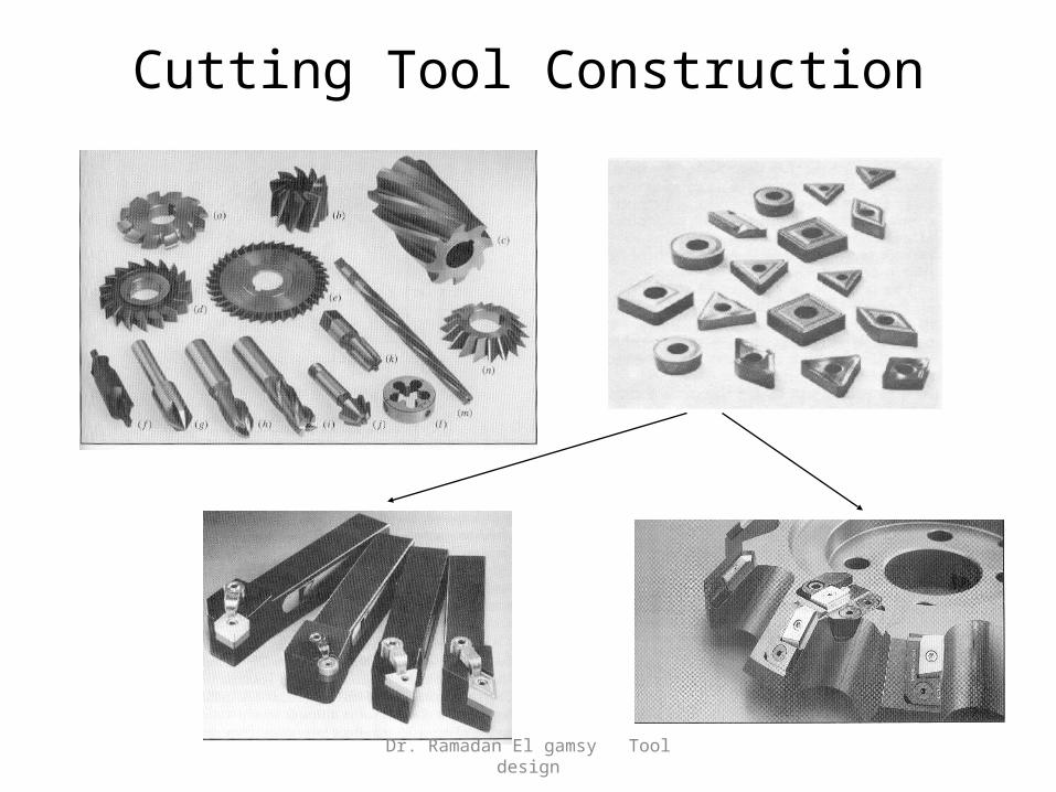
Cutting Tool Construction
Dr. Ramadan El gamsy Tool design
Types of tool materials
o Carbon steelo High speed steel (HSS)o Cemented Carbideso Cast alloyso Ceramicso Cubic boron nitride (CBN)o Diamond
Dr. Ramadan El gamsy Tool design
Carbon Steel
• Oldest of tool materials• Used for drills taps,broaches ,reamers• Inexpensive ,easily shaped ,sharpened• No sufficient hardness and wear
resistance• Limited to low cutting speed
operation
Dr. Ramadan El gamsy Tool design
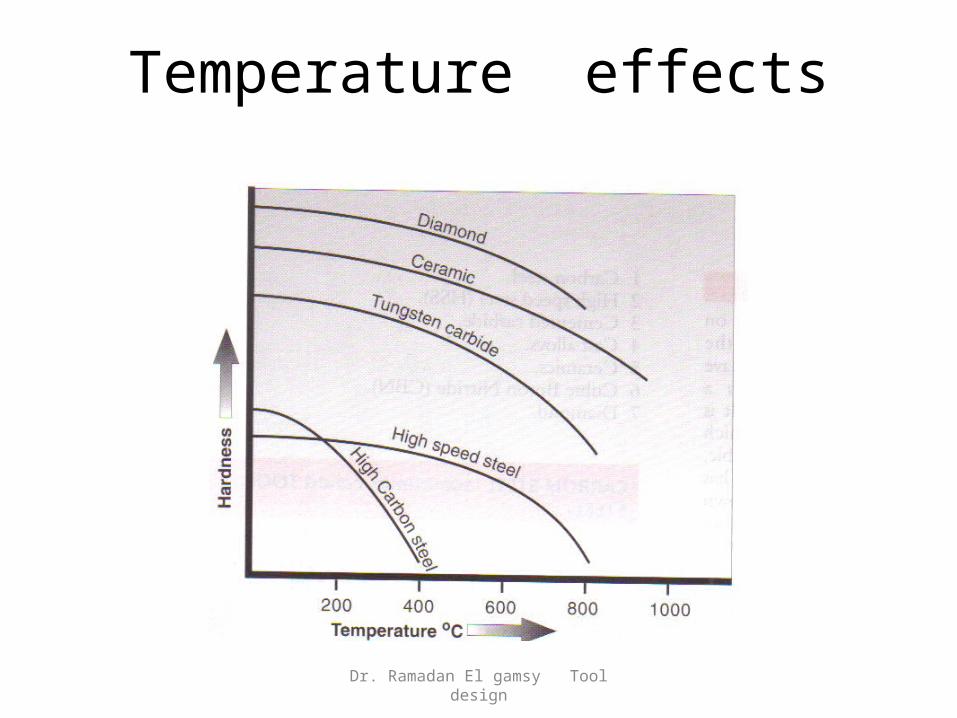
Temperature effects
Dr. Ramadan El gamsy Tool design
High speed steel
• Retains its hardness at high temperature• Red hardness….• Relatively good wear resistance
Dr. Ramadan El gamsy Tool design
Tungsten Carbide
• Composite material consisting of tungsten-carbide particles bonded together
• Alternate name is cemented carbides
• Manufactured with powder metallurgy techniques
• Small particles are pressed & sintered to desired shape • Amount of cobalt present affects properties of carbide tools • As cobalt content increases – the tougher the tool
Dr. Ramadan El gamsy Tool design
Cast alloys
• Commonly known as stellite tools• Composition ranges – 38% - 53 % cobalt
30%- 33% chromium10%-20%tungsten
• Good wear resistance ( higher hardness)• Less tough than high-speed steels and sensitive to impact forces• Less suitable than high-speed steels for interrupted cutting operations• Continuous roughing cuts – relatively high g=feeds & speeds• Finishing cuts are at lower feed and depth of cut
Dr. Ramadan El gamsy Tool design
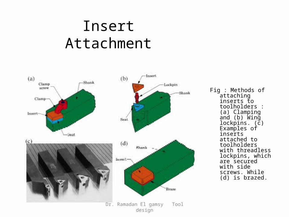
Insert Attachment
Fig : Methods of attaching inserts to toolholders : (a) Clamping and (b) Wing lockpins. (c) Examples of inserts attached to toolholders with threadless lockpins, which are secured with side screws. While (d) is brazed.
Dr. Ramadan El gamsy Tool design
Ceramics
• Used as grinding wheels.
• as cutting tool inserts. These are used in a similar way to cemented carbide inserts.
• they can withstand extremely high machining temperatures.
• They also have a high resistance to abrasion.
Dr. Ramadan El gamsy Tool design
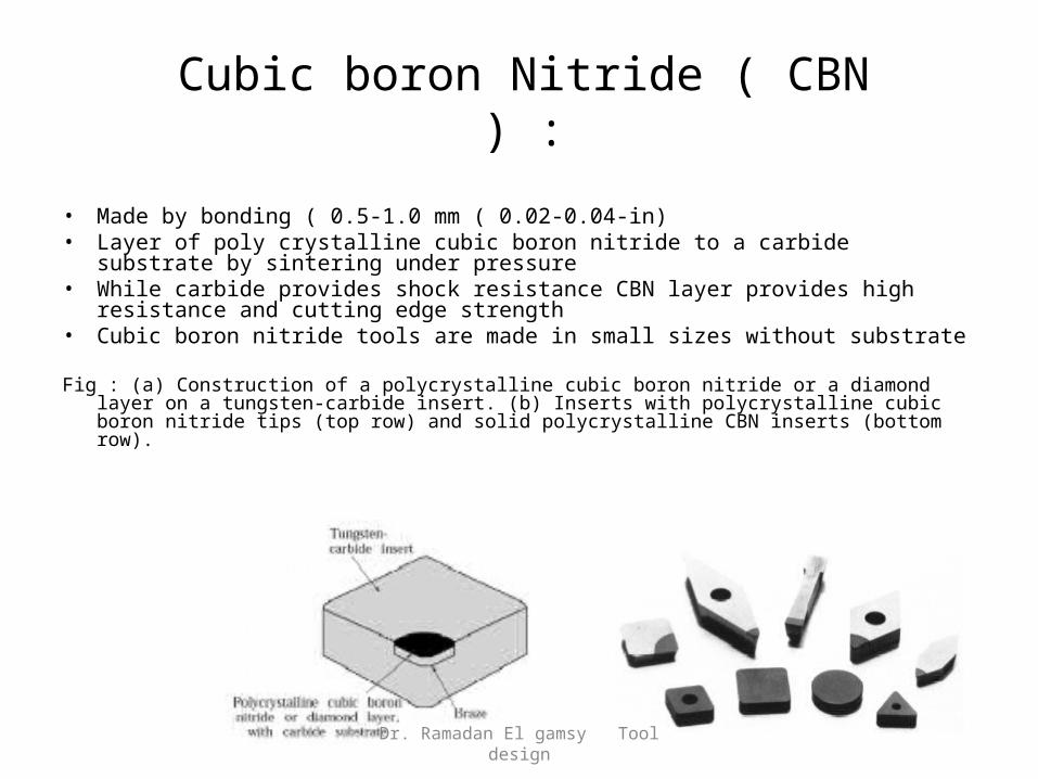
Cubic boron Nitride ( CBN ) :
• Made by bonding ( 0.5-1.0 mm ( 0.02-0.04-in)• Layer of poly crystalline cubic boron nitride to a carbide substrate by
sintering under pressure• While carbide provides shock resistance CBN layer provides high
resistance and cutting edge strength• Cubic boron nitride tools are made in small sizes without substrate
Fig : (a) Construction of a polycrystalline cubic boron nitride or a diamond layer on a tungsten-carbide insert. (b) Inserts with polycrystalline cubic boron nitride tips (top row) and solid polycrystalline CBN inserts (bottom row).
Dr. Ramadan El gamsy Tool design
Diamond :
• Hardest known substance • Low friction, high wear resistance• Ability to maintain sharp cutting edge• Single crystal diamond of various carats used
for special applications• Machining copper—front precision optical
mirrors for ( SDI)• Diamond is brittle , tool shape & sharpened is
important• Low rake angle used for string cutting edge
Dr. Ramadan El gamsy Tool design
Single Point Cutting Tool
Dr. Ramadan El gamsy Tool design
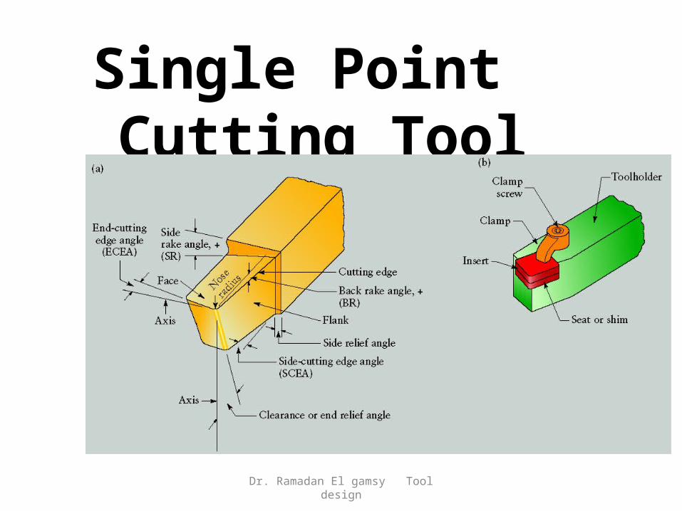
Single Point Cutting Tool
Dr. Ramadan El gamsy Tool design
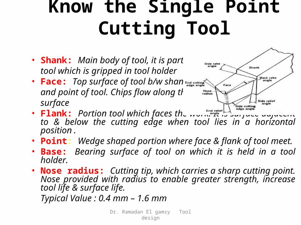
Know the Single Point Cutting Tool
• Shank: Main body of tool, it is part of tool which is gripped in tool holder
• Face: Top surface of tool b/w shankand point of tool. Chips flow along this surface
• Flank: Portion tool which faces the work. It is surface adjacent to & below the cutting edge when tool lies in a horizontal position.
• Point: Wedge shaped portion where face & flank of tool meet.• Base: Bearing surface of tool on which it is held in a tool holder.• Nose radius: Cutting tip, which carries a sharp cutting point.
Nose provided with radius to enable greater strength, increase tool life & surface life. Typical Value : 0.4 mm – 1.6 mm
Dr. Ramadan El gamsy Tool design
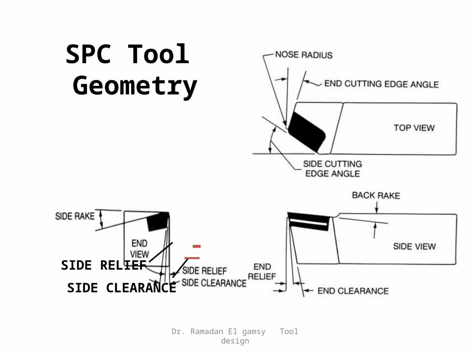
SPC Tool Geometry
SIDE RELIEF
SIDE CLEARANCE
Dr. Ramadan El gamsy Tool design
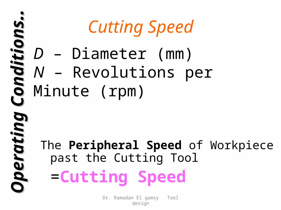
Cutting Speed
The Peripheral Speed of Workpiece past the Cutting Tool
=Cutting SpeedOp
era
tin
g
Op
era
tin
g
Con
dit
ion
sC
on
dit
ion
s ....
D – Diameter (mm)N – Revolutions per Minute (rpm)
Dr. Ramadan El gamsy Tool design
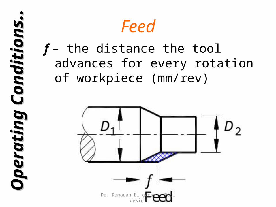
Feedf – the distance the tool advances for every
rotation of workpiece (mm/rev)
Op
era
tin
g
Op
era
tin
g
Con
dit
ion
sC
on
dit
ion
s ....
Dr. Ramadan El gamsy Tool design
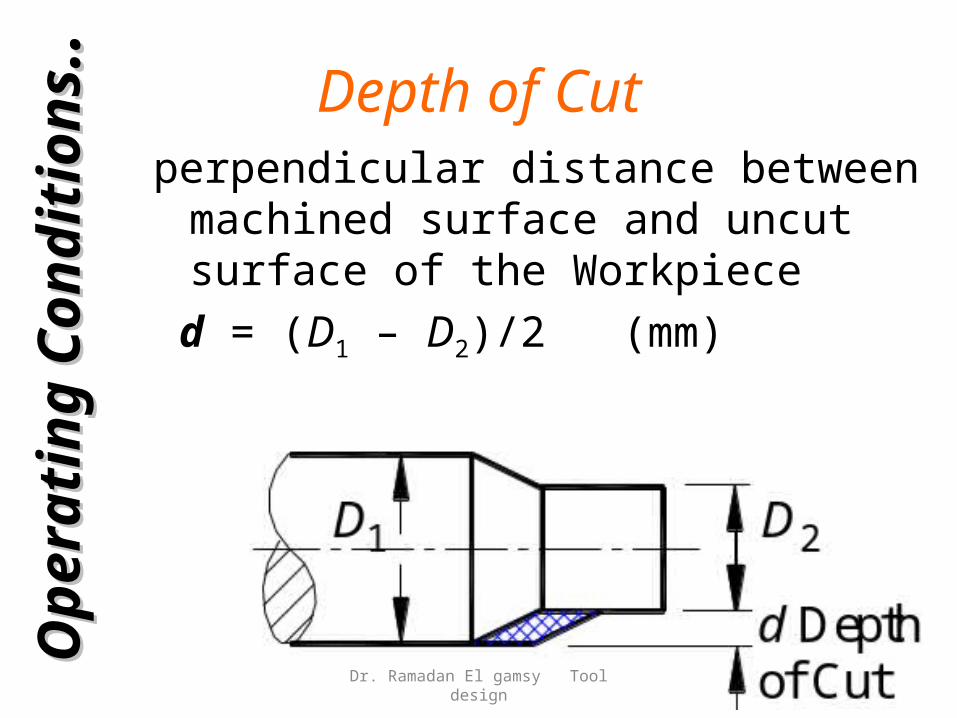
Depth of Cutperpendicular distance between machined
surface and uncut surface of the Workpiece d = (D1 – D2)/2 (mm)
Op
era
tin
g
Op
era
tin
g
Con
dit
ion
sC
on
dit
ion
s ....
Dr. Ramadan El gamsy Tool design
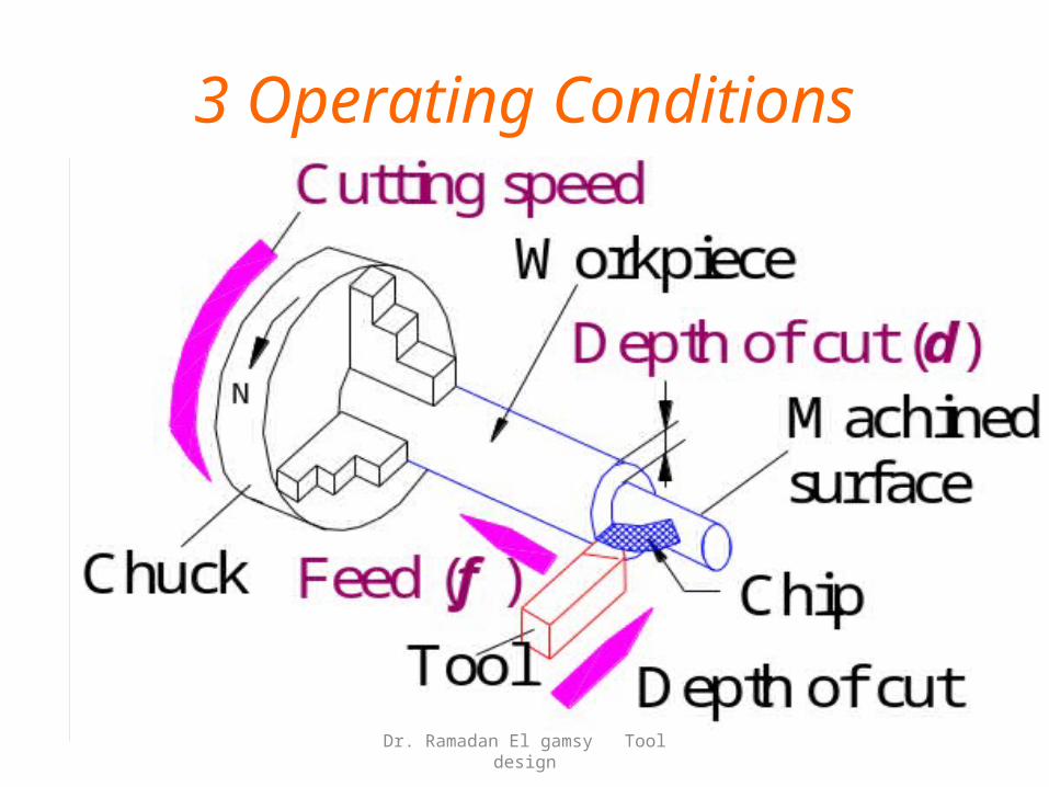
3 Operating Conditions
Dr. Ramadan El gamsy Tool design
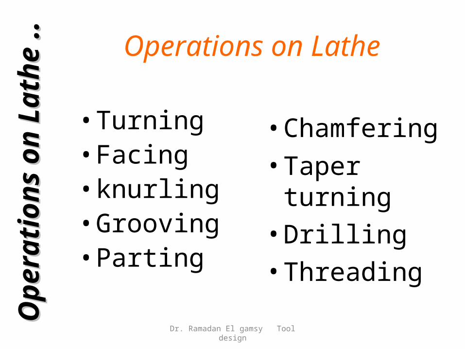
Operations on Lathe
• Turning• Facing• knurling• Grooving• Parting
• Chamfering• Taper turning• Drilling• Threading
Op
era
tion
s o
n
Op
era
tion
s o
n
Lath
eLath
e .
. .
.
Dr. Ramadan El gamsy Tool design
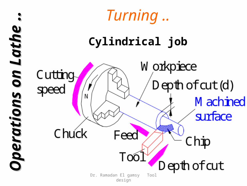
Turning ..
Cylindrical job
Op
era
tion
s o
n
Op
era
tion
s o
n
Lath
eLath
e .
. .
.
Dr. Ramadan El gamsy Tool design
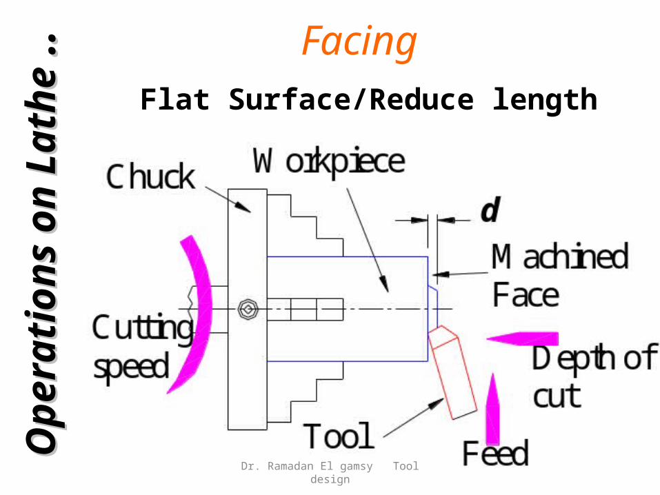
FacingFlat Surface/Reduce length
Op
era
tion
s o
n
Op
era
tion
s o
n
Lath
eLath
e .
. .
.
Dr. Ramadan El gamsy Tool design
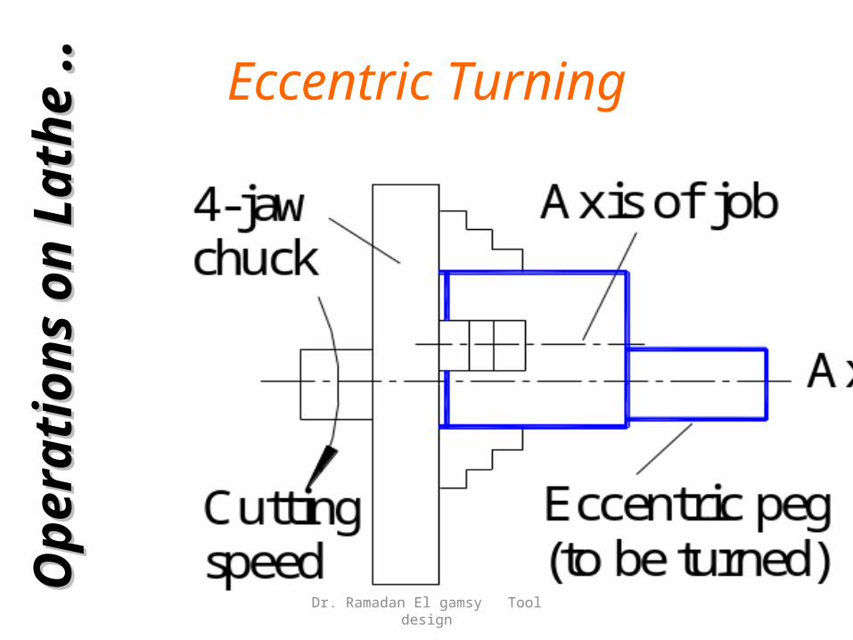
Eccentric TurningO
pera
tion
s o
n
Op
era
tion
s o
n
Lath
eLath
e .
. .
.
Dr. Ramadan El gamsy Tool design
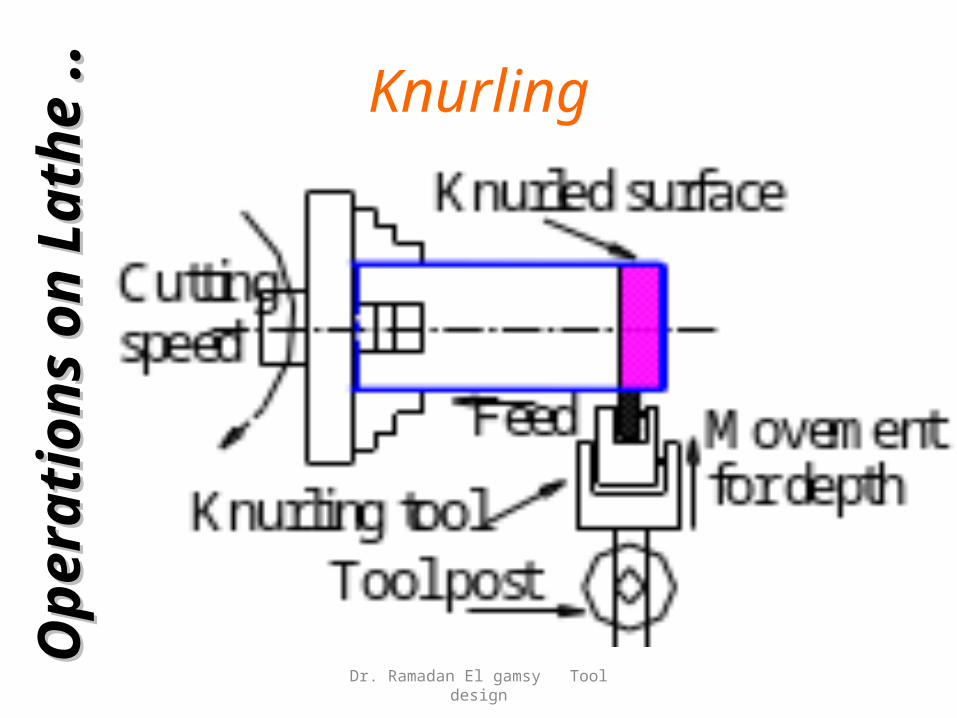
KnurlingO
pera
tion
s o
n
Op
era
tion
s o
n
Lath
eLath
e .
. .
.
Dr. Ramadan El gamsy Tool design
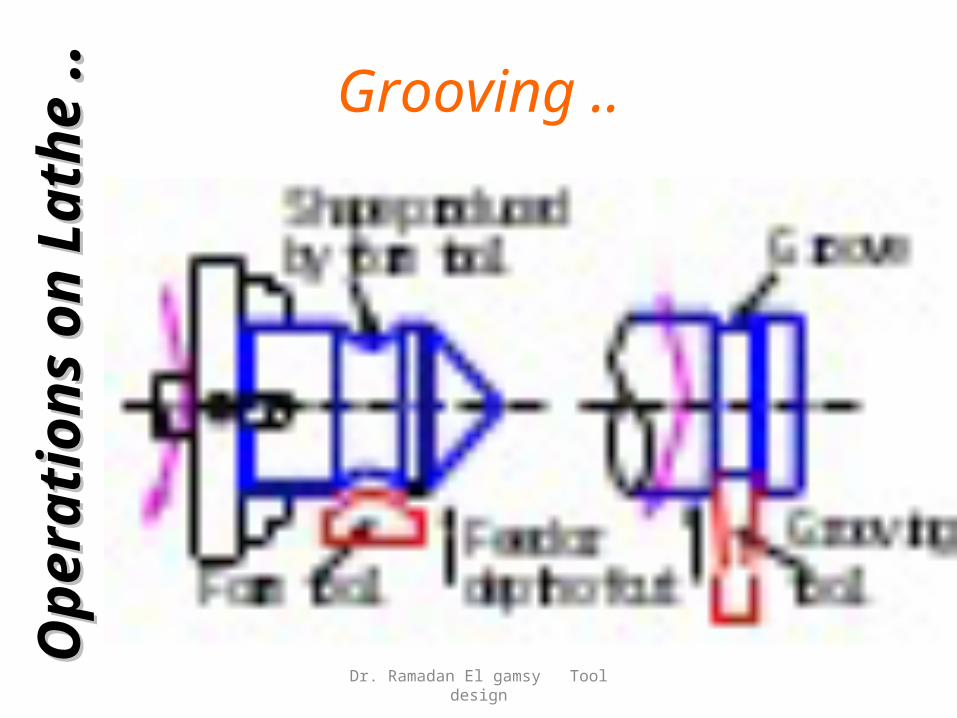
Grooving ..O
pera
tion
s o
n
Op
era
tion
s o
n
Lath
eLath
e .
. .
.
Dr. Ramadan El gamsy Tool design
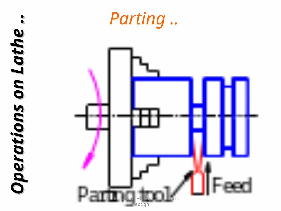
Parting ..O
pera
tion
s o
n
Op
era
tion
s o
n
Lath
eLath
e .
. .
.
Dr. Ramadan El gamsy Tool design
ChamferingO
pera
tion
s o
n
Op
era
tion
s o
n
Lath
eLath
e .
. .
.
Dr. Ramadan El gamsy Tool design
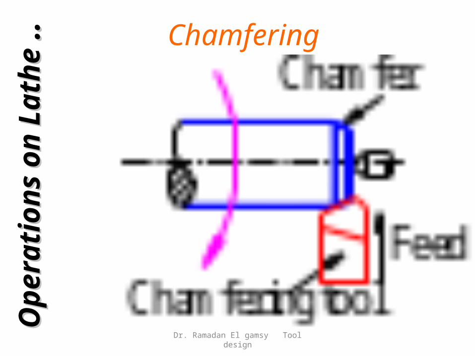
Chamfering
Beveling sharp machined edges Similar to form turning Chamfering tool – 45° To
• Avoid Sharp Edges• Make Assembly Easier
Op
era
tion
s o
n
Op
era
tion
s o
n
Lath
eLath
e .
. .
.
Dr. Ramadan El gamsy Tool design
Taper Turning..
MethodsMethods • Form Tool• Swiveling Compound Rest• Taper Turning Attachment• Simultaneous Longitudinal and
Cross FeedsOp
era
tion
s o
n
Op
era
tion
s o
n
Lath
eLath
e .
. .
.Conicity
Dr. Ramadan El gamsy Tool design

Taper Turning ..By Form Tool
Op
era
tion
s o
n
Op
era
tion
s o
n
Lath
eLath
e .
. .
.
Dr. Ramadan El gamsy Tool design
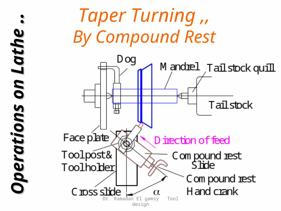
Taper Turning ,,By Compound Rest
Op
era
tion
s o
n
Op
era
tion
s o
n
Lath
eLath
e .
. .
.
Dr. Ramadan El gamsy Tool design
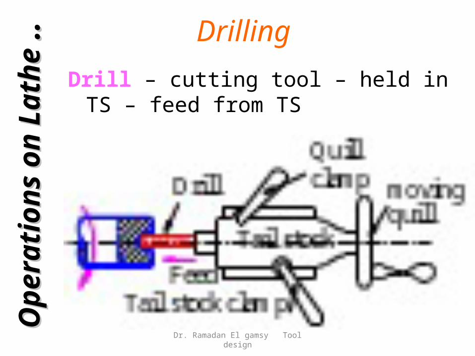
Drilling
Drill – cutting tool – held in TS – feed from TS
Op
era
tion
s o
n
Op
era
tion
s o
n
Lath
eLath
e .
. .
.
Dr. Ramadan El gamsy Tool design
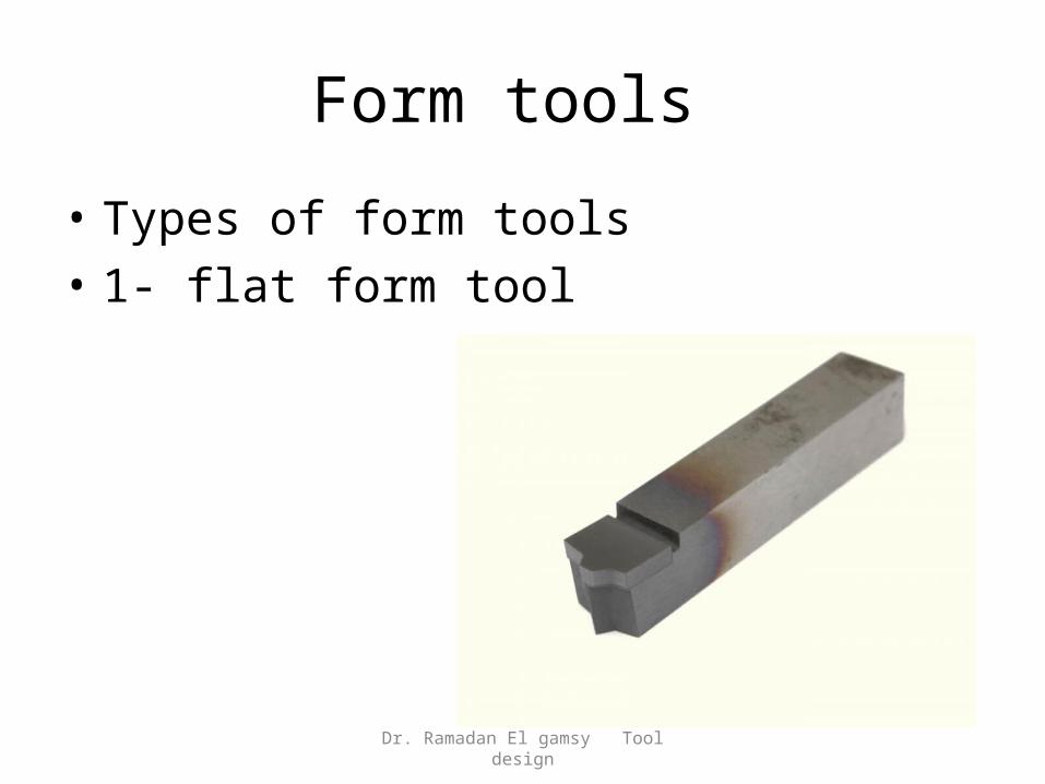
Form tools
• Types of form tools• 1- flat form tool
Dr. Ramadan El gamsy Tool design
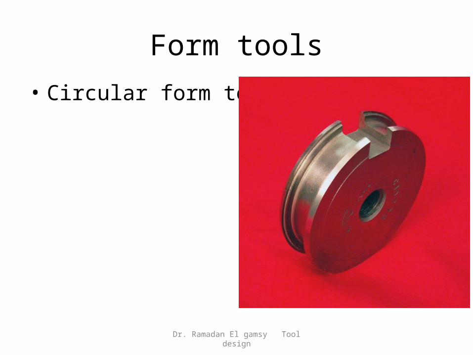
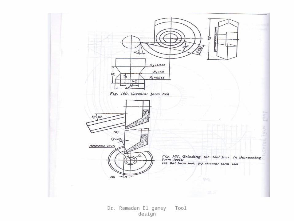
Form tools• Circular form tool
Dr. Ramadan El gamsy Tool design
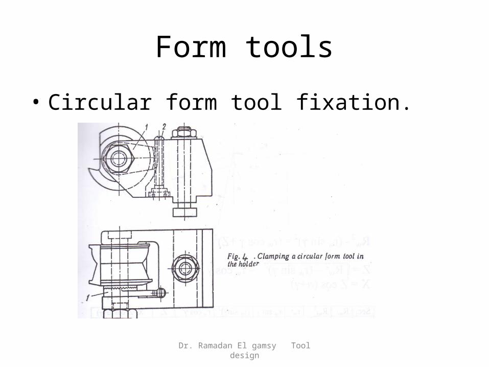
Form tools
• Circular form tool fixation.
Dr. Ramadan El gamsy Tool design
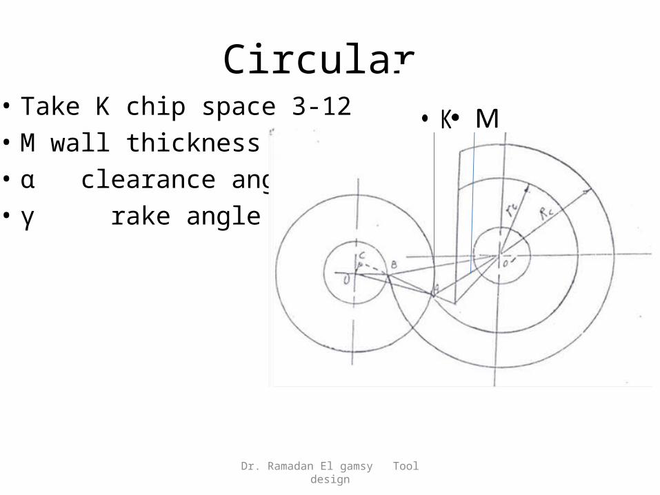
Circular
Dr. Ramadan El gamsy Tool design
• Take K chip space 3-12• M wall thickness 6-8• α clearance angle• γ rake angle
kk
Form tools
• Advantages of form tools.• Cross feed is reducing the machining time.• High accuracy in marching formed shapes.• The first product is the same as last one.• High production rate.
Dr. Ramadan El gamsy Tool design
Form profile
• There are two ways for produce the tool form.1- Graphical method.2- Analytical method.
1- graphical method for flat tool
Dr. Ramadan El gamsy Tool design
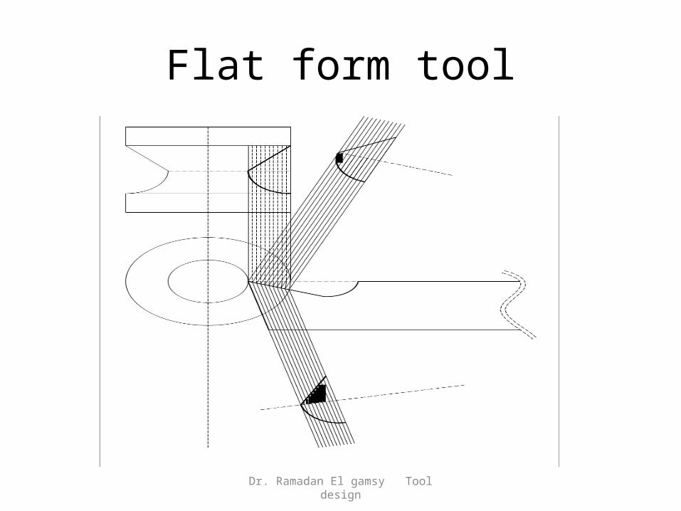
Flat form tool
Dr. Ramadan El gamsy Tool design
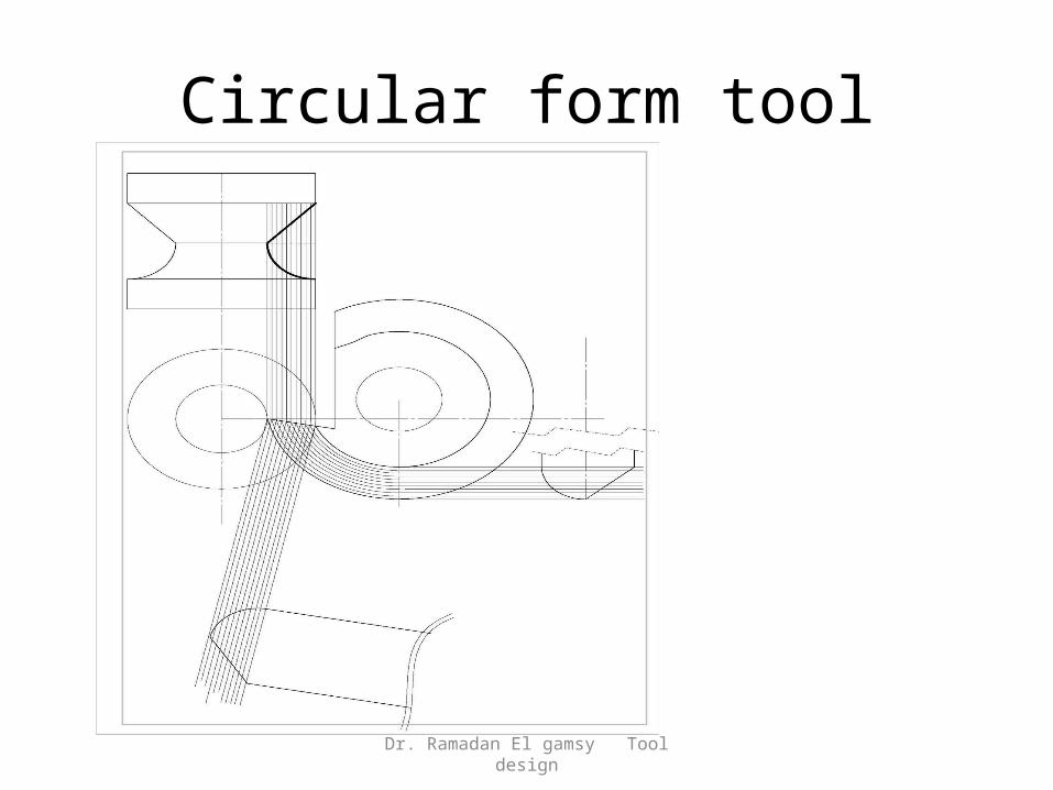
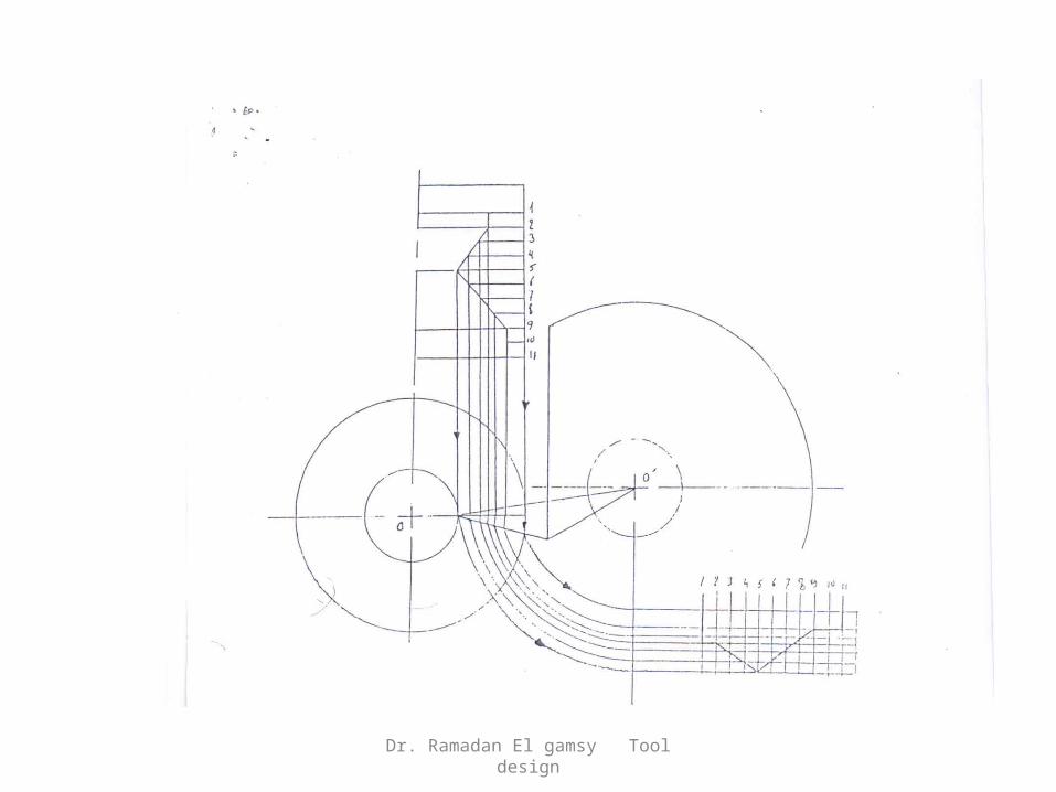
Circular form tool
Dr. Ramadan El gamsy Tool design
Dr. Ramadan El gamsy Tool design

Analytical method.Flat type
Dr. Ramadan El gamsy Tool design
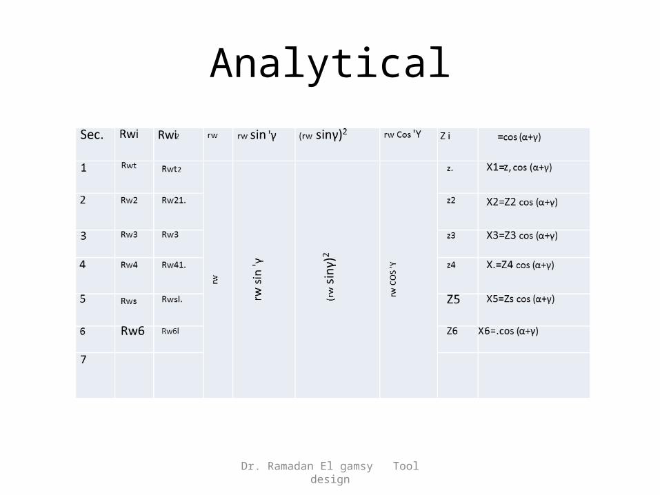
Analytical
Dr. Ramadan El gamsy Tool design
Dr. Ramadan El gamsy Tool design
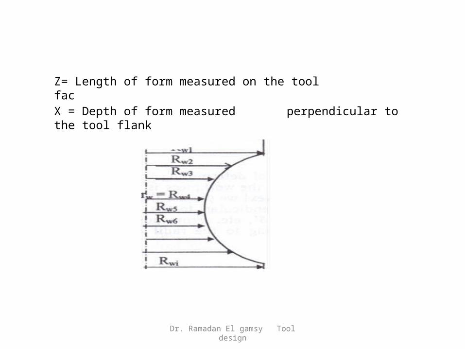
Z= Length of form measured on the tool fac
X = Depth of form measured perpendicular to the tool flank
Dr. Ramadan El gamsy Tool design