Embed Size (px)
Citation preview

Multimedia Systems
Image III
(Image Compression, JPEG)
Mahdi Amiri
November 2015
Sharif University of Technology
Course Presentation

Multimedia Systems, Mahdi Amiri, Image IIIPage 1
Image CompressionBasics
Large amount of data in digital images
File size for a 14 Megapixel color image
42 MB in uncompressed RGB 24bit/pixel format
~ 24 images in a 1GB memory card
~1.5 MB in JPEG (90% quality) format
~ 667 images in a 1GB memory card
Compression crucial
Different number of techniques available
RLE, LZ, ADPCM, DCT
Choice depends on
Type of image (B/W, Grayscale, Color, Content)
Application (Entertainment, Medial, Real-time)
30 fps Video in a 1TB HDD
~ 13 min. uncompressed
~ 6 hours and 15 min. MJPEG1TB

Multimedia Systems, Mahdi Amiri, Image IIIPage 2
Image CompressionDPCM for Images

Multimedia Systems, Mahdi Amiri, Image IIIPage 3
Image CompressionJPEG
Most commonly used still image compression
method
Image files, cameras, and WWW
Lossy Compression
(inc. a lossless coding mode too)
Adjustable degree of compression
Tradeoff between storage size and image quality
Typ. Compression ratio: 10:1
(with little perceptible loss in image quality)
Supports a max. image size of 65535x65535
Original
178 KB
Q: 50
37 KB
Q: 5
16 KB
Q: 1
13 KB
Ref.: en.wikipedia.org/wiki/JPEG

Multimedia Systems, Mahdi Amiri, Image IIIPage 4
Image CompressionRate-Distortion Curve
R, Rate: Number of bits per symbol (pixel)
D, Distortion: Difference between input and output
Ex. 1: Mean Squared Error (MSE) of the difference between input and
output signal
Ex. 2: Peak Signal-To-Noise Ratio ( PSNR)
Input: Original image
Output: Reconstructed image
We will talk more about PSNR at:
Topic: Video III, SubTopic: Video Quality Evaluation
A problem to think about:
Given a random variable (here all images of the world) and a distortion measure,
what is the minimum expected distortion achievable at a particular rate?
Equivalently, What is the minimum rate required to achieve a distortion?
… An optimization problem, one solution: Lloyd Algorithm.
Rate–distortion theory was created by
Claude Shannon in his foundational
work on information theory.

Multimedia Systems, Mahdi Amiri, Image IIIPage 5
Image CompressionJPEG
Acronym for the
“Joint Photographic Experts Group”
A sub-groups of ISO/IEC
http://www.jpeg.org/
The group was organized in 1986
First public release date
JPEG part 1 standard, 1992
ISO: International Organization for Standardization, www.iso.org, NGO, since 1947.
IEC: International Electrotechnical Commission, www.iec.ch, NPO/NGO, since 1906.

Multimedia Systems, Mahdi Amiri, Image IIIPage 6
Image CompressionJPEG
Pro:
Works well on photographs and paintings of
realistic scenes with smooth variations of tone
and color.
Con:
Lossy compression in the typical use ���� is not
suitable for certain applications such as medical
imaging.
Not proper for line drawings and other textual
or iconic graphics, where the sharp contrasts
between adjacent pixels can cause noticeable
artifacts.Grass Test Image
House Test Image

Multimedia Systems, Mahdi Amiri, Image IIIPage 7
Image CompressionJPEG Encoder Steps
Color space transformation: RGB to YCbCrThe representation of the colors in the image is converted from RGB to Y′CBCR, consisting of one luma component (Y'),
representing brightness, and two chroma components, (Cb and Cr), representing color. This step is sometimes skipped.
Chroma subsamplingThe resolution of the chroma data is reduced, usually by a factor of 2. This reflects the fact that the eye is less sensitive to fine color
details than to fine brightness details.
Block splitting and DCTThe image is split into blocks of 8×8 pixels. For each block, each of the Y, Cb, and Cr data undergoes a discrete cosine transform
(DCT). A DCT is similar to a Fourier transform in the sense that it produces a kind of spatial frequency spectrum.
QuantizationThe amplitudes of the frequency components are quantized. Human vision is much more sensitive to small variations in color or
brightness over large areas than to the strength of high-frequency brightness variations. Therefore, the magnitudes of the high-
frequency components are stored with a lower accuracy than the low-frequency components. The quality setting of the encoder (for
example 50 or 95 on a scale of 0–100 in the Independent JPEG Group's library) affects to what extent the resolution of each
frequency component is reduced. If an excessively low quality setting is used, the high-frequency components are discarded
altogether.
Entropy CodingThe resulting data for all 8×8 blocks is further compressed with a lossless algorithm, a variant of Huffman encoding.

Multimedia Systems, Mahdi Amiri, Image IIIPage 8
JPEGCodec Diagram, Scheme 1
Encoder
Decoder

Multimedia Systems, Mahdi Amiri, Image IIIPage 9
JPEGEncoder Diagram, Scheme 2
JPEG encoder diagram for a single block of 8 by 8 pixels

Multimedia Systems, Mahdi Amiri, Image IIIPage 10
JPEGEncoder Diagram, Scheme 3
Baseline JPEG
Encoder
block diagram

Multimedia Systems, Mahdi Amiri, Image IIIPage 11
JPEGColor Space Transformation
RGB to YCbCr conversion concept:
The human eye is less sensitive to fine color (chrominance)
details than to fine brightness (luminance) details.
Analog TV
Digital TV
Cb = B – Y
Cr = R - Y

Multimedia Systems, Mahdi Amiri, Image IIIPage 12
JPEG, Chroma SubsamplingSubsampling in YCbCr

Multimedia Systems, Mahdi Amiri, Image IIIPage 13
JPEGBlock Splitting and DCT
Block splitting
The image is split into blocks of 8×8 pixels.
Later we discuss why this is done.
Discrete Cosine Transform (DCT)
Each 8×8 block of each component (Y, Cb, Cr) is
converted to a frequency-domain representation, using
a normalized, two-dimensional type-II discrete cosine
transform (DCT).

Multimedia Systems, Mahdi Amiri, Image IIIPage 14
JPEG, DCTCenter Around Zero
The 8×8 sub-image shown
in 8-bit grayscale

Multimedia Systems, Mahdi Amiri, Image IIIPage 15
JPEG, DCTFourier Coefficients
square-wave synthesized using Fourier cosine coefficients and sine coefficients

Multimedia Systems, Mahdi Amiri, Image IIIPage 16
DCTBasis Functions
The DCT transforms an 8×8 block of
input values to a linear combination
of these 64 patterns. The patterns are
referred to as the two-dimensional
DCT basis functions, and the output
values are referred to as transform
coefficients. The horizontal index is u
and the vertical index is v.
The 8×8
sub-image

Multimedia Systems, Mahdi Amiri, Image IIIPage 17
JPEG, DCTIllustration of DCT

Multimedia Systems, Mahdi Amiri, Image IIIPage 18
JPEG, DCTDCT Coefficients
DC coefficient ( Top-left corner, has large magnitude )
AC coefficients ( Other 63 coefficients )
DCT aggregates most of the signal in one corner
Larger values in the top-left corner
DCT coefficient for our sample block (rounded to the nearest two digits beyond the decimal point)

Multimedia Systems, Mahdi Amiri, Image IIIPage 19
JPEGDCT Coefficients, Example
The result of taking the DCT. The numbers in red are the
coefficients that fall below the specified threshold of 10.

Multimedia Systems, Mahdi Amiri, Image IIIPage 20
JPEG, DCTHistograms of DCT Coefficients
Histograms of DCT
Coefficients of image
‘lena’ using blocks of
8×8 pixels

Multimedia Systems, Mahdi Amiri, Image IIIPage 21
JPEG, QuantizationConcept
The human eye is good at seeing small
differences in brightness over a relatively large
area, but not so good at distinguishing the exact
strength of a high frequency brightness variation.
Small quantization step for low frequency
components (Top-left corner in DCT
coefficients matrix )
Big quantization step for high frequency
components (Bottom-right corner in DCT
coefficients matrix )DCT coefficient
Sample Images

Multimedia Systems, Mahdi Amiri, Image IIIPage 22
JPEG, QuantizationQuantization Matrix
A typical quantization matrix, as specified in the original
JPEG Standard
G is the unquantized DCT coefficients
Q is the quantization matrix
B is the quantized DCT coefficients

Multimedia Systems, Mahdi Amiri, Image IIIPage 23
JPEG, QuantizationSample Output
Many of the higher frequency components are rounded
to zero
Quantized DCT coefficient for our sample block

Multimedia Systems, Mahdi Amiri, Image IIIPage 24
JPEG, Quantization

Multimedia Systems, Mahdi Amiri, Image IIIPage 25
JPEG, Quantization MatrixQuality Factor
The quality setting of the encoder (for example 50 or 95
on a scale of 0–100 in the Independent JPEG Group's
library) affects to what extent the resolution of each
frequency component is reduced.
For a quality of 100%, the quantization tables should be
setup such that all entries are one. For a quality factor of
50%, the ITU/ISO recommended tables are recommended,
but any other choice is also valid. For a quality between
50% and 100%, one may interpolate between the quality
factor given for 50%, and that for 100% (i.e. 1.0)

Multimedia Systems, Mahdi Amiri, Image IIIPage 26
JPEG, Entropy CodingZigzag Ordering
DC Coefficient: DPCM
AC Coefficients
Run-length encoding ( RLE )
Then using Huffman coding
on the whole sequence of numbers

Multimedia Systems, Mahdi Amiri, Image IIIPage 27
JPEGEncoder Example

Multimedia Systems, Mahdi Amiri, Image IIIPage 28
JPEGDecoder Example

Multimedia Systems, Mahdi Amiri, Image IIIPage 29
JPEGCompression Ratio
Original JPEG Compressed
Quality setting of 50
Difference
(Darker means a larger
difference)

Multimedia Systems, Mahdi Amiri, Image IIIPage 30
JPEGMWIPC
MWIPC, Testing DPCM and DCT based image compression

Multimedia Systems, Mahdi Amiri, Image IIIPage 31
JPEGBlocking Artifact
Original JPEG Compressed
Quality setting of 5

Multimedia Systems, Mahdi Amiri, Image IIIPage 32
JPEG, Block SplittingBlocks of 8 by 8 Pixels
Why Blocking?
Neighboring pixels are more correlated.
Lower computational complexity.
The computational complexity for 2D DCT of an
N by N image is:
, while the complexity of 2D DCT of all N/8 by
N/8 blocks of image is:
( )2
2logO N N
( ) ( )2
2 2
228 log 8
8
NO O N=
What about blocks of 16×16 pixels?
PaddingIf the data for a channel does not represent
an integer number of blocks then the
encoder must fill the remaining area of the
incomplete blocks with some form of
dummy data.

Multimedia Systems, Mahdi Amiri, Image IIIPage 33
JPEG, Block SplittingLarger Blocks
Pro: Less blocking artifact
Con:
Less Correlated data inside the block
Higher computational complexity
Efficiency as a function of block size
N×N, measured for 8 bit quantization
in the original domain and equivalent
quantization in the transform domain.
Block size 8×8 is a good
compromise between coding
efficiency and complexity

Multimedia Systems, Mahdi Amiri, Image IIIPage 34
JPEG, ImplementationsLibjpeg
Distributed as free software together with its source code.
Developer: Independent JPEG Group.
It was first published in 1991 and was key for the success of the
standard.
Cross-platform.
Ref.: en.wikipedia.org/wiki/Libjpeg
http://ijg.org/
Version 9b 10-Jan-2016:
Improvements and optimizations in DCT and color calculations.
Normalize range limit array composition and access pattern.

Multimedia Systems, Mahdi Amiri, Image IIIPage 35
JPEG, ModesLossless Mode
The JPEG standard actually includes a lossless coding mode, but
that mode is not supported in most products.
Lossless mode uses DPCM (using a combination of up to 3
neighboring pixels) and Huffman entropy encoder.

Multimedia Systems, Mahdi Amiri, Image IIIPage 36
JPEG, ModesBaseline vs Progressive Rendering
Baseline: load line by line; takes much longer to render a complete
image.
Progressive: shows a low-quality photo in its entirety, and then
becomes clearer as the image’s data becomes more fully downloaded.
Ref.: sixrevisions.com/graphics-design/jpeg-101-a-crash-course-guide-on-jpeg/
Multimedia Systems, Mahdi Amiri, Image IIIPage 37
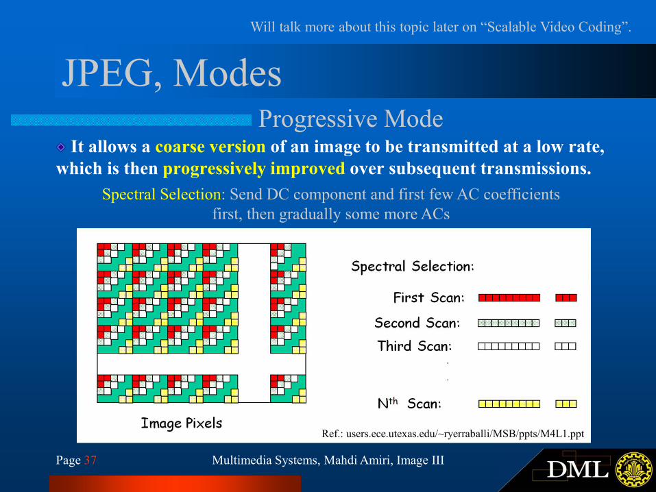
JPEG, ModesProgressive Mode
It allows a coarse version of an image to be transmitted at a low rate,
which is then progressively improved over subsequent transmissions.
Will talk more about this topic later on “Scalable Video Coding”.
Spectral Selection: Send DC component and first few AC coefficients
first, then gradually some more ACs
Ref.: users.ece.utexas.edu/~ryerraballi/MSB/ppts/M4L1.ppt

Multimedia Systems, Mahdi Amiri, Image IIIPage 38
JPEG, ModesProgressive Mode
Successive Approximation: All the DCT components are sent few bits at a time: For example,
send n1 (say,4) bits (starting with MSB) of all pixels in the first scan, the next n2(say 1) bits of
all pixels in the second and so on.
Ref.: users.ece.utexas.edu/~ryerraballi/MSB/ppts/M4L1.ppt

Multimedia Systems, Mahdi Amiri, Image IIIPage 39
JPEG, ModesHierarchical Mode
Will talk more about this topic later on “Scalable Video Coding”.
Ref.: users.ece.utexas.edu/~ryerraballi/MSB/ppts/M4L1.ppt
Used primarily to support multiple resolutions of the same image which can be
chosen from depending on the target’s capabilities.
Image pyramid

Multimedia Systems, Mahdi Amiri, Image IIIPage 40
JPEGCons.
Isn’t good for images with sharp edges such as text, cartoon drawings, and
so forth. You should choose PNG or GIF for such images.
Does not currently support traditional transparency.

Multimedia Systems, Mahdi Amiri, Image IIIPage 41
GIF and PNGPortable Network Graphics.
PNG and GIF both are lossless image compression. PNG Motivation:
In 1995, the Lempel–Ziv–Welch (LZW) data compression algorithm used in the
Graphics Interchange Format (GIF) format was patented by Unisys.
The GIF format was limited of 256 colors.
PNG uses a 2-stage compression process:
Pre-compression: Prediction (DPCM)
DEFLATE algorithm (LZ77 + Huffman coding)
PNG can use the data in pixels A, B,
and C to predict the value for X.
comparing lossy compression in
JPEG with lossless compression in
PNG: the JPEG artifacts are easily
visible in the background, where the
PNG image has solid color.

Multimedia Systems, Mahdi Amiri, Image IIIPage 42
JPEGJPEG vs PNG
JPEG vs. PNG

Multimedia Systems, Mahdi Amiri, Image IIIPage 43
Thank You
1. http://ce.sharif.edu/~m_amiri/
2. http://www.aictc.ir/
FIND OUT MORE AT...
Multimedia Systems
Image III (Compression, JPEG)
Next Session: Video I