Embed Size (px)
DESCRIPTION
brown university lecture 1
Citation preview

1
ENGN1300: Structural Analysis
Spring, 2010
Division of Engineering
Brown University
The goal of the course is to enable you to
analyze relatively complex structures by
creating appropriate mathematical
idealizations, and studying these using
various solid mechanics concepts, most
notably energy methods.
2
1. Be able to analyze complex structures, such as frames,
trusses, and suspension bridges using matrix and energy
minimization methods
2. Be able to analyze truss, beam, and frame structures using
the finite element method ─ understanding the derivation
of the equations by means of the principle of virtual work
and write simple finite element codes.
3. Be able to compute natural frequencies and mode shapes
for various
4. Be able predict and understand the dynamic response of
structures to wind, earthquake, and other periodic forcing.
Objectives
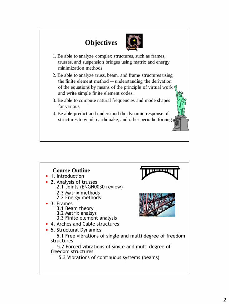
Course Outline• 1. Introduction
• 2. Analysis of trusses2.1 Joints (ENGN0030 review)
2.3 Matrix methods2.2 Energy methods
• 3. Frames3.1 Beam theory3.2 Matrix analsys3.3 Finite element analysis
• 4. Arches and Cable structures
• 5. Structural Dynamics
5.1 Free vibrations of single and multi degree of freedom structures
5.2 Forced vibrations of single and multi degree of freedom structures
5.3 Vibrations of continuous systems (beams)

3
Organization
• Instructor
J. A. Blume, 741 B&H
Office hours MW 11-12am,
or any other time
• TA
Jennet Toyjanova
Office Hourse Monday, 8-9pm, BH 096
Grading
• Homework: 30% (Lowest grade will be dropped)
• Midterm Exam (in class, Wednesday 3/24): 20%
• Final Exam: (9am Monday, 5/17): 40%
• Class attendance and participation: 10%
Exams are open notes.

4
Issues in Structural Design
• Strength?
• Life?
• Deformation?
• Stability?
• Vibrations?
• Material Selection
• Shape
Optimization
• Cost
• Manufacturability
Applications: Buildings/shelters

5
Aerospace
Biological Structure

6
Automotive Industry
Of Course: Bridges

8
This is What You Need:
• Physical Intuition• Analytical methods for
solution for force,
deflection
• Numerical
determination of
force, deflection
Ingredients:
• Newton’s Laws (kinetics)
• Deformation
(kinematics) y
x x
y
l0
l0
xx
yy
l0
l0
e1
e2
xy
O A
BC
OA
B C
e1
e3
e2
11
12
13
21
22
23
31
32
33
9
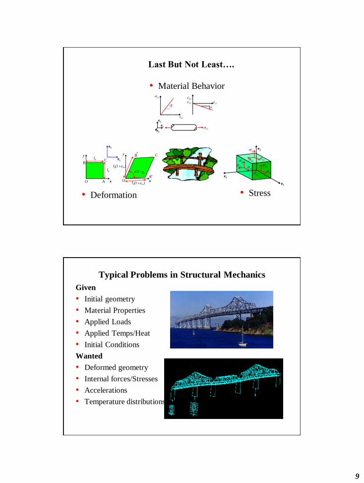
Last But Not Least….
• Material Behavior
• Stress
e1
e3
e2
11
12
13
21
22
23
31
32
33
y
x x
y
l0
l0
xx
yy
l0
l0
e1
e2
xy
O A
BC
OA
B C
• Deformation
E
e1
e2
e3
Typical Problems in Structural Mechanics
Given
• Initial geometry
• Material Properties
• Applied Loads
• Applied Temps/Heat
• Initial Conditions
Wanted
• Deformed geometry
• Internal forces/Stresses
• Accelerations
• Temperature distributions
10
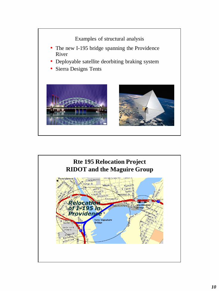
Examples of structural analysis
• The new I-195 bridge spanning the Providence River
• Deployable satellite deorbiting braking system
• Sierra Designs Tents
Rte 195 Relocation Project
RIDOT and the Maguire Group

11
Main Relocation Features
• 1 mile of new rte 195
• 1.5 miles of resurfaced and realigned 195
• New interchange with rte 95
• 13 new ramp bridges
• 50-ft wide pedestrian bridge over 195 to India Point Park
• Network Arch signature span over the Providence River (950 ft bridge)
Main Bridge
• 400 foot span triple barreled steel tied network
arch with intersecting hangers, also known as a
Nielson-Lohse bridge.

12
Some Basic Questions
• Stresses in the arch and deck
• Cable tensions: during construction and during
service
• Vibrational behavior
-20
0
20
40
60
80
100
120
-50 0 50 100 150 200 250 300 350 400 450

13
26
27
220 kips
1000 kN
14
28
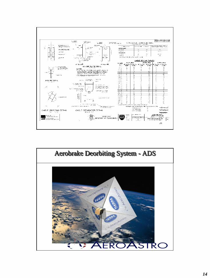
Aerobrake Deorbiting System - ADS
15
. 32
The Problem and the Opportunity
Today a spacecraft remaining in LEO for any appreciable length of time will be struck by space debris, most likely several times. • At best the impact will simply puncture a non-
essential piece of structure; • At worst will cause a catastrophic failure of
the spacecraft and generate additional debris. • AeroAstro’s solution is a low-cost, robust,
self-contained Aerobrake Deorbiting System (ADS), which will retire a space asset at the
end of its useful lifetime.
The ADS sets itself apart from other technologies:• It does not only target one class of spacecraft, but across multiple classes• Imposes only a small mass and size penalty to the target spacecraft – much less than
maintaining a percentage of fuel in reserve for deorbiting purposes. • If only the aerobrake is deployed, and every other system fails, the ADS will hasten the
time to deorbit• If the spacecraft angular rates are too high post-deployment, damping provided by
embedded conductive wire. This will be embedded in the membrane structure near it’s periphery.
. 35
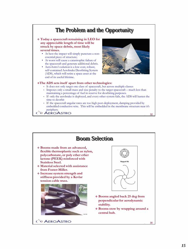
Boom Selection
Booms made from an advanced, flexible thermoplastic such as nylon, polycarbonate, or poly ether ether ketone (PEEK) reinforced with Stainless Steel.
Material selected with assistance from Foster-Miller.
Increase system strength and stiffness provided by a Kevlar tension cable truss.
Booms angled back 25 deg from
perpendicular for aerodynamic
stability.
Booms stow by wrapping around a
central hub.

16
. 37
North Sails 3DL process
The 3DL process was developed and patented by North Sails.
They have been producing 3DL laminates since 1992 for the marine
industry.
The 3DL process laminates high strength and high modulus fibers
between thin layers of Kapton or Mylar producing a flexible composite
membrane.
The 3DL process allows the strength and stiffness to be tailored the
expected loads and loading direction.
. 38
Deployment Sequence
1. Pin puller releases the
shroud
2. Shroud springs away from
the package and covers
potential deployment
hazards
3. Booms unwrap, pulling
the membrane and cables
with them
4. Hub expands to full height
5. Cables are pulled tight by
the deploying booms
17
. 39
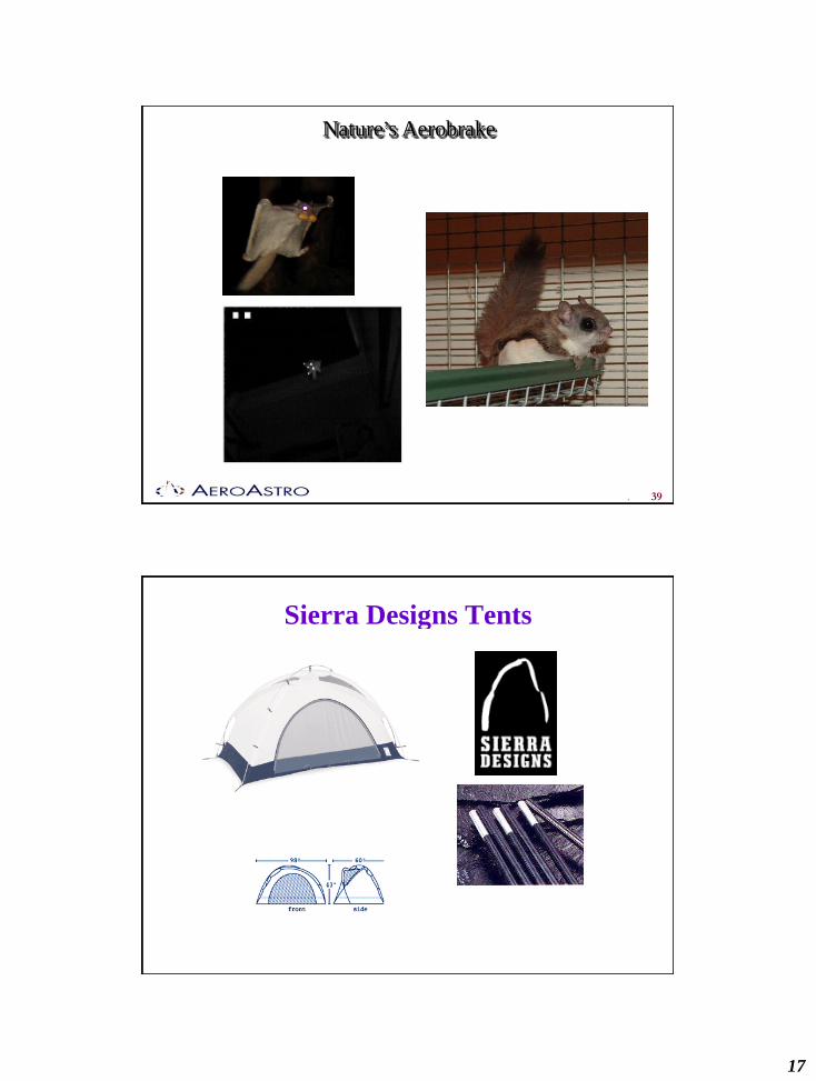
Nature’s Aerobrake
Sierra Designs Tents
18
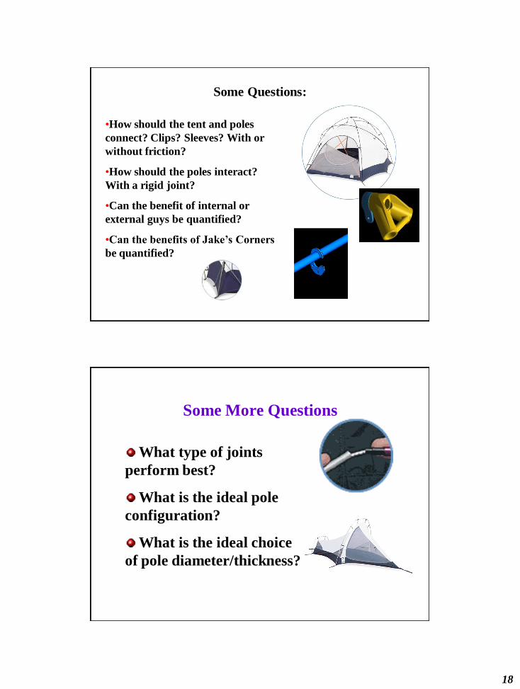
Some Questions:
•How should the tent and poles
connect? Clips? Sleeves? With or
without friction?
•How should the poles interact?
With a rigid joint?
•Can the benefit of internal or
external guys be quantified?
•Can the benefits of Jake’s Corners
be quantified?
Some More Questions
What type of joints
perform best?
What is the ideal pole
configuration?
What is the ideal choice
of pole diameter/thickness?
19
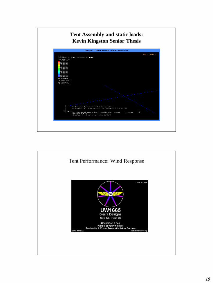
Tent Assembly and static loads:
Kevin Kingston Senior Thesis
Tent Performance: Wind Response

20
Tent Performance: Wind Response