Embed Size (px)
Citation preview
Lecture 1Lectures 1 - 7 are based on The Shape of Space, by Jeff Weeks
1. Creating universes by gluing
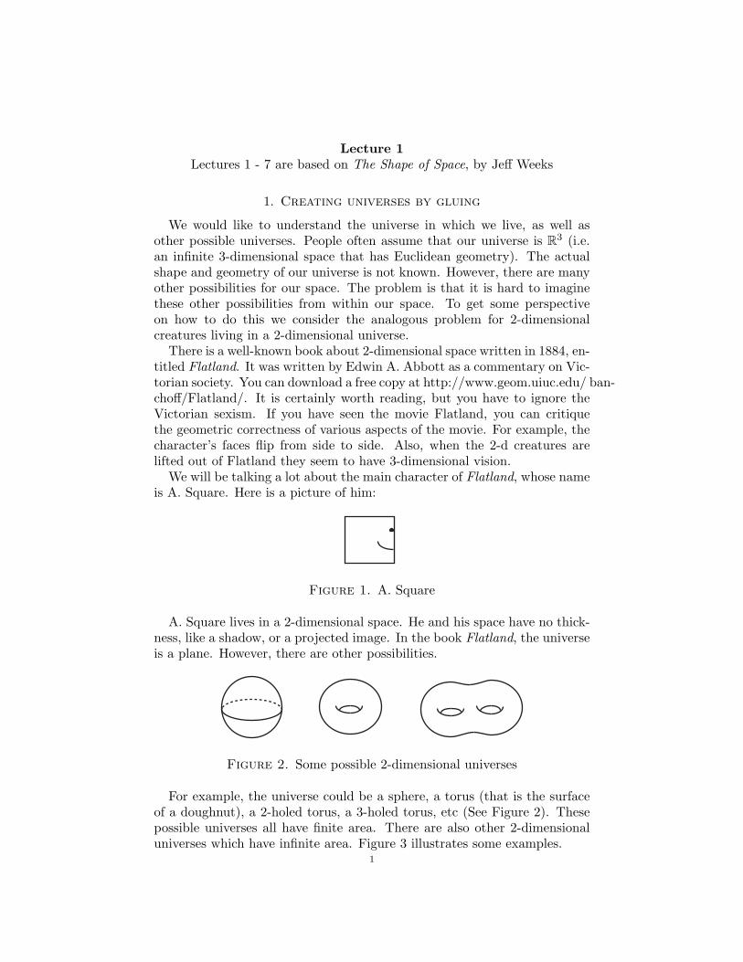
We would like to understand the universe in which we live, as well asother possible universes. People often assume that our universe is R3 (i.e.an infinite 3-dimensional space that has Euclidean geometry). The actualshape and geometry of our universe is not known. However, there are manyother possibilities for our space. The problem is that it is hard to imaginethese other possibilities from within our space. To get some perspectiveon how to do this we consider the analogous problem for 2-dimensionalcreatures living in a 2-dimensional universe.
There is a well-known book about 2-dimensional space written in 1884, en-titled Flatland. It was written by Edwin A. Abbott as a commentary on Vic-torian society. You can download a free copy at http://www.geom.uiuc.edu/ ban-choff/Flatland/. It is certainly worth reading, but you have to ignore theVictorian sexism. If you have seen the movie Flatland, you can critiquethe geometric correctness of various aspects of the movie. For example, thecharacter’s faces flip from side to side. Also, when the 2-d creatures arelifted out of Flatland they seem to have 3-dimensional vision.
We will be talking a lot about the main character of Flatland, whose nameis A. Square. Here is a picture of him:
Figure 1. A. Square
A. Square lives in a 2-dimensional space. He and his space have no thick-ness, like a shadow, or a projected image. In the book Flatland, the universeis a plane. However, there are other possibilities.
Figure 2. Some possible 2-dimensional universes
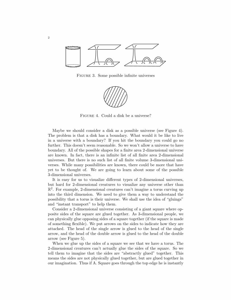
For example, the universe could be a sphere, a torus (that is the surfaceof a doughnut), a 2-holed torus, a 3-holed torus, etc (See Figure 2). Thesepossible universes all have finite area. There are also other 2-dimensionaluniverses which have infinite area. Figure 3 illustrates some examples.
1
2
Figure 3. Some possible infinite universes
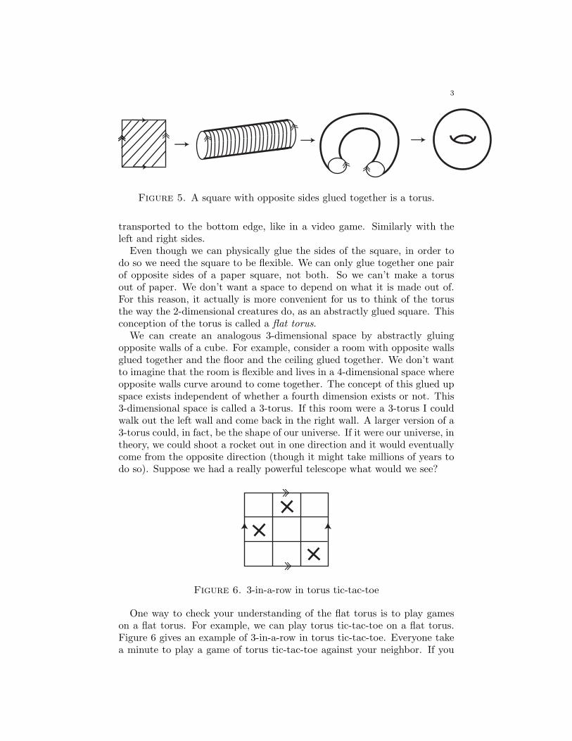
Figure 4. Could a disk be a universe?
Maybe we should consider a disk as a possible universe (see Figure 4).The problem is that a disk has a boundary. What would it be like to livein a universe with a boundary? If you hit the boundary you could go nofurther. This doesn’t seem reasonable. So we won’t allow a universe to haveboundary. All of the possible shapes for a finite area 2-dimensional universeare known. In fact, there is an infinite list of all finite area 2-dimensionaluniverses. But there is no such list of all finite volume 3-dimensional uni-verses. While many possibilities are known, there could be more that haveyet to be thought of. We are going to learn about some of the possible3-dimensional universes.
It is easy for us to visualize different types of 2-dimensional universes,but hard for 2-dimensional creatures to visualize any universe other thanR2. For example, 2-dimensional creatures can’t imagine a torus curving upinto the third dimension. We need to give them a way to understand thepossibility that a torus is their universe. We shall use the idea of “gluings”and “instant transport” to help them.
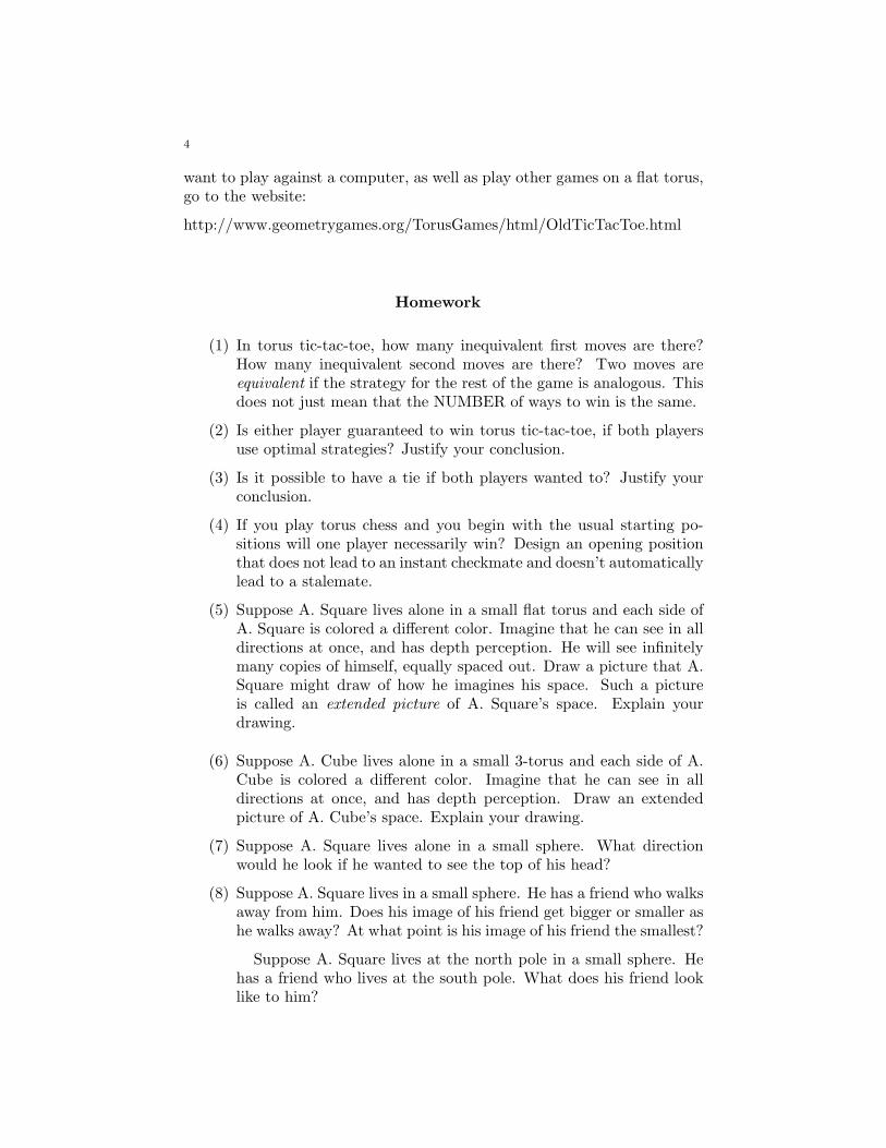
Consider a 2-dimensional universe consisting of a giant square where op-posite sides of the square are glued together. As 3-dimensional people, wecan physically glue opposing sides of a square together (if the square is madeof something flexible). We put arrows on the sides to indicate how they areattached. The head of the single arrow is glued to the head of the singlearrow, and the head of the double arrow is glued to the head of the doublearrow (see Figure 5).
When we glue up the sides of a square we see that we have a torus. The2-dimensional creatures can’t actually glue the sides of the square. So wetell them to imagine that the sides are “abstractly glued” together. Thismeans the sides are not physically glued together, but are glued together inour imagination. Thus if A. Square goes through the top edge he is instantly
3
Figure 5. A square with opposite sides glued together is a torus.
transported to the bottom edge, like in a video game. Similarly with theleft and right sides.
Even though we can physically glue the sides of the square, in order todo so we need the square to be flexible. We can only glue together one pairof opposite sides of a paper square, not both. So we can’t make a torusout of paper. We don’t want a space to depend on what it is made out of.For this reason, it actually is more convenient for us to think of the torusthe way the 2-dimensional creatures do, as an abstractly glued square. Thisconception of the torus is called a flat torus.
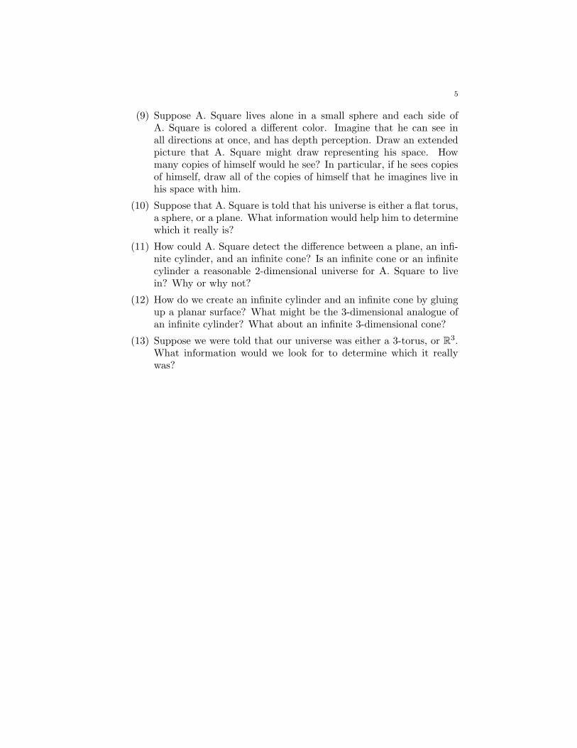
We can create an analogous 3-dimensional space by abstractly gluingopposite walls of a cube. For example, consider a room with opposite wallsglued together and the floor and the ceiling glued together. We don’t wantto imagine that the room is flexible and lives in a 4-dimensional space whereopposite walls curve around to come together. The concept of this glued upspace exists independent of whether a fourth dimension exists or not. This3-dimensional space is called a 3-torus. If this room were a 3-torus I couldwalk out the left wall and come back in the right wall. A larger version of a3-torus could, in fact, be the shape of our universe. If it were our universe, intheory, we could shoot a rocket out in one direction and it would eventuallycome from the opposite direction (though it might take millions of years todo so). Suppose we had a really powerful telescope what would we see?
Figure 6. 3-in-a-row in torus tic-tac-toe
One way to check your understanding of the flat torus is to play gameson a flat torus. For example, we can play torus tic-tac-toe on a flat torus.Figure 6 gives an example of 3-in-a-row in torus tic-tac-toe. Everyone takea minute to play a game of torus tic-tac-toe against your neighbor. If you
4
want to play against a computer, as well as play other games on a flat torus,go to the website:
http://www.geometrygames.org/TorusGames/html/OldTicTacToe.html
Homework
(1) In torus tic-tac-toe, how many inequivalent first moves are there?How many inequivalent second moves are there? Two moves areequivalent if the strategy for the rest of the game is analogous. Thisdoes not just mean that the NUMBER of ways to win is the same.
(2) Is either player guaranteed to win torus tic-tac-toe, if both playersuse optimal strategies? Justify your conclusion.
(3) Is it possible to have a tie if both players wanted to? Justify yourconclusion.
(4) If you play torus chess and you begin with the usual starting po-sitions will one player necessarily win? Design an opening positionthat does not lead to an instant checkmate and doesn’t automaticallylead to a stalemate.
(5) Suppose A. Square lives alone in a small flat torus and each side ofA. Square is colored a different color. Imagine that he can see in alldirections at once, and has depth perception. He will see infinitelymany copies of himself, equally spaced out. Draw a picture that A.Square might draw of how he imagines his space. Such a pictureis called an extended picture of A. Square’s space. Explain yourdrawing.
(6) Suppose A. Cube lives alone in a small 3-torus and each side of A.Cube is colored a different color. Imagine that he can see in alldirections at once, and has depth perception. Draw an extendedpicture of A. Cube’s space. Explain your drawing.
(7) Suppose A. Square lives alone in a small sphere. What directionwould he look if he wanted to see the top of his head?
(8) Suppose A. Square lives in a small sphere. He has a friend who walksaway from him. Does his image of his friend get bigger or smaller ashe walks away? At what point is his image of his friend the smallest?
Suppose A. Square lives at the north pole in a small sphere. Hehas a friend who lives at the south pole. What does his friend looklike to him?
5
(9) Suppose A. Square lives alone in a small sphere and each side ofA. Square is colored a different color. Imagine that he can see inall directions at once, and has depth perception. Draw an extendedpicture that A. Square might draw representing his space. Howmany copies of himself would he see? In particular, if he sees copiesof himself, draw all of the copies of himself that he imagines live inhis space with him.
(10) Suppose that A. Square is told that his universe is either a flat torus,a sphere, or a plane. What information would help him to determinewhich it really is?
(11) How could A. Square detect the difference between a plane, an infi-nite cylinder, and an infinite cone? Is an infinite cone or an infinitecylinder a reasonable 2-dimensional universe for A. Square to livein? Why or why not?
(12) How do we create an infinite cylinder and an infinite cone by gluingup a planar surface? What might be the 3-dimensional analogue ofan infinite cylinder? What about an infinite 3-dimensional cone?
(13) Suppose we were told that our universe was either a 3-torus, or R3.What information would we look for to determine which it reallywas?
Lecture 2
1. Visualizing higher dimensions
We would like to use our understanding of dimensions 1, 2, and 3, totry to visualize a fourth dimension. People often like to think of the fourthdimension as time. If I want to meet someone I have to specify not only threespatial coordinates (e.g., on the second floor of the building on Broadwayand 95th street), but also a time coordinate (e.g. at 9:00 AM on June 29th).In fact, no matter how many spatial dimensions you live in you can alwaysadd a time dimension. So time isn’t really the fourth dimension, it is an(n + 1)th dimension for anyone who lives in n dimensions.
However, considering time as a dimension does not help us visualize 4-dimensional space. Also, mathematicians like symmetry so we prefer alldimensions to be equivalent. There is no particular dimension which isthe first dimension, and another which is the second dimension, and so on.Rather, dimensions 1, 2, and 3 are all equivalent. So dimension 4 should beequivalent to the others as well.
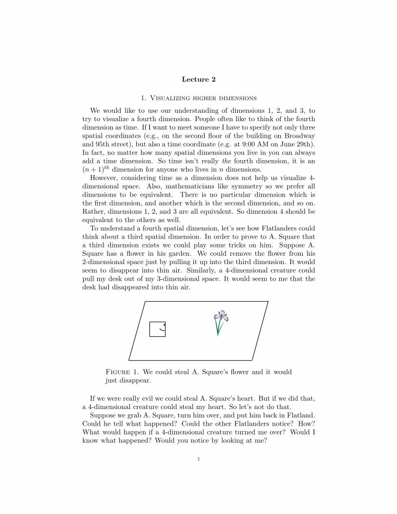
To understand a fourth spatial dimension, let’s see how Flatlanders couldthink about a third spatial dimension. In order to prove to A. Square thata third dimension exists we could play some tricks on him. Suppose A.Square has a flower in his garden. We could remove the flower from his2-dimensional space just by pulling it up into the third dimension. It wouldseem to disappear into thin air. Similarly, a 4-dimensional creature couldpull my desk out of my 3-dimensional space. It would seem to me that thedesk had disappeared into thin air.
Figure 1. We could steal A. Square’s flower and it wouldjust disappear.
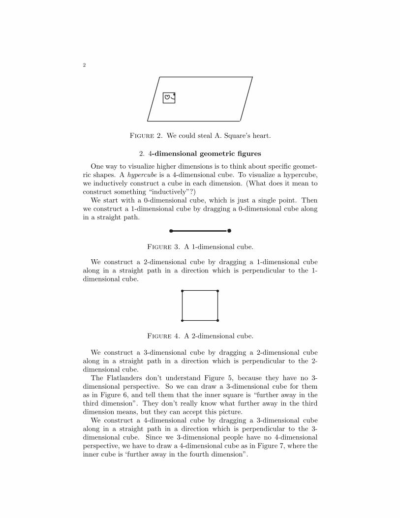
If we were really evil we could steal A. Square’s heart. But if we did that,a 4-dimensional creature could steal my heart. So let’s not do that.
Suppose we grab A. Square, turn him over, and put him back in Flatland.Could he tell what happened? Could the other Flatlanders notice? How?What would happen if a 4-dimensional creature turned me over? Would Iknow what happened? Would you notice by looking at me?
1
2
Figure 2. We could steal A. Square’s heart.
2. 4-dimensional geometric figures
One way to visualize higher dimensions is to think about specific geomet-ric shapes. A hypercube is a 4-dimensional cube. To visualize a hypercube,we inductively construct a cube in each dimension. (What does it mean toconstruct something “inductively”?)
We start with a 0-dimensional cube, which is just a single point. Thenwe construct a 1-dimensional cube by dragging a 0-dimensional cube alongin a straight path.
Figure 3. A 1-dimensional cube.
We construct a 2-dimensional cube by dragging a 1-dimensional cubealong in a straight path in a direction which is perpendicular to the 1-dimensional cube.
Figure 4. A 2-dimensional cube.
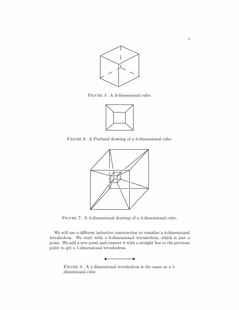
We construct a 3-dimensional cube by dragging a 2-dimensional cubealong in a straight path in a direction which is perpendicular to the 2-dimensional cube.
The Flatlanders don’t understand Figure 5, because they have no 3-dimensional perspective. So we can draw a 3-dimensional cube for themas in Figure 6, and tell them that the inner square is “further away in thethird dimension”. They don’t really know what further away in the thirddimension means, but they can accept this picture.
We construct a 4-dimensional cube by dragging a 3-dimensional cubealong in a straight path in a direction which is perpendicular to the 3-dimensional cube. Since we 3-dimensional people have no 4-dimensionalperspective, we have to draw a 4-dimensional cube as in Figure 7, where theinner cube is ‘further away in the fourth dimension”.
3
Figure 5. A 3-dimensional cube.
Figure 6. A Flatland drawing of a 3-dimensional cube.
Figure 7. A 3-dimensional drawing of a 4-dimensional cube.
We will use a different inductive construction to visualize a 4-dimensionaltetrahedron. We start with a 0-dimensional tetrahedron, which is just apoint. We add a new point and connect it with a straight line to the previouspoint to get a 1-dimensional tetrahedron.
Figure 8. A 1-dimensional tetrahedron is the same as a 1-dimensional cube
4
Now we add a new point which is equidistant from the previous two points.We connect this new point to the previous points to get a 2-dimensionaltetrahedron (see Figure 9).
Figure 9. A 2-dimensional tetrahedron
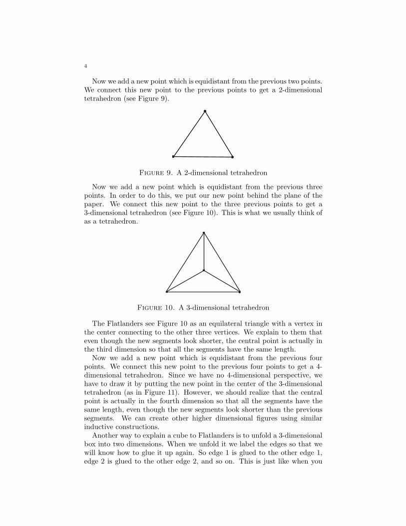
Now we add a new point which is equidistant from the previous threepoints. In order to do this, we put our new point behind the plane of thepaper. We connect this new point to the three previous points to get a3-dimensional tetrahedron (see Figure 10). This is what we usually think ofas a tetrahedron.
Figure 10. A 3-dimensional tetrahedron
The Flatlanders see Figure 10 as an equilateral triangle with a vertex inthe center connecting to the other three vertices. We explain to them thateven though the new segments look shorter, the central point is actually inthe third dimension so that all the segments have the same length.
Now we add a new point which is equidistant from the previous fourpoints. We connect this new point to the previous four points to get a 4-dimensional tetrahedron. Since we have no 4-dimensional perspective, wehave to draw it by putting the new point in the center of the 3-dimensionaltetrahedron (as in Figure 11). However, we should realize that the centralpoint is actually in the fourth dimension so that all the segments have thesame length, even though the new segments look shorter than the previoussegments. We can create other higher dimensional figures using similarinductive constructions.
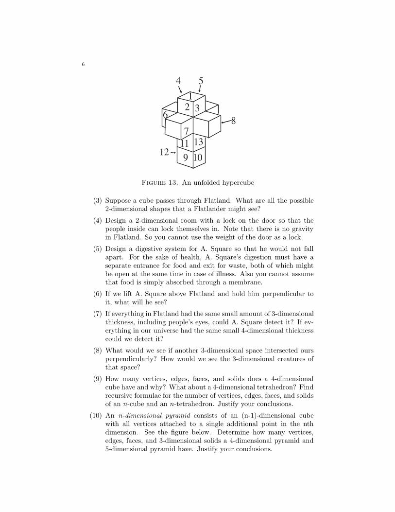
Another way to explain a cube to Flatlanders is to unfold a 3-dimensionalbox into two dimensions. When we unfold it we label the edges so that wewill know how to glue it up again. So edge 1 is glued to the other edge 1,edge 2 is glued to the other edge 2, and so on. This is just like when you
5
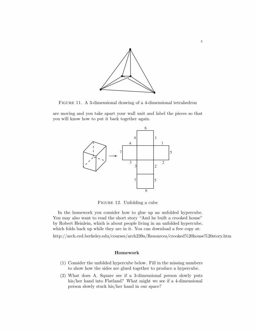
Figure 11. A 3-dimensional drawing of a 4-dimensional tetrahedron
are moving and you take apart your wall unit and label the pieces so thatyou will know how to put it back together again.
6
6
3
3
2
7 5
5
4 1
2
4 1
7
Figure 12. Unfolding a cube
In the homework you consider how to glue up an unfolded hypercube.You may also want to read the short story “And he built a crooked house”by Robert Heinlein, which is about people living in an unfolded hypercube,which folds back up while they are in it. You can download a free copy at:
http://arch.ced.berkeley.edu/courses/arch239a/Resources/crooked%20house%20story.htm
Homework
(1) Consider the unfolded hypercube below. Fill in the missing numbersto show how the sides are glued together to produce a hypercube.
(2) What does A. Square see if a 3-dimensional person slowly putshis/her hand into Flatland? What might we see if a 4-dimensionalperson slowly stuck his/her hand in our space?
6
9
7
86
54
32
1
1012
1311
Figure 13. An unfolded hypercube
(3) Suppose a cube passes through Flatland. What are all the possible2-dimensional shapes that a Flatlander might see?
(4) Design a 2-dimensional room with a lock on the door so that thepeople inside can lock themselves in. Note that there is no gravityin Flatland. So you cannot use the weight of the door as a lock.
(5) Design a digestive system for A. Square so that he would not fallapart. For the sake of health, A. Square’s digestion must have aseparate entrance for food and exit for waste, both of which mightbe open at the same time in case of illness. Also you cannot assumethat food is simply absorbed through a membrane.
(6) If we lift A. Square above Flatland and hold him perpendicular toit, what will he see?
(7) If everything in Flatland had the same small amount of 3-dimensionalthickness, including people’s eyes, could A. Square detect it? If ev-erything in our universe had the same small 4-dimensional thicknesscould we detect it?
(8) What would we see if another 3-dimensional space intersected oursperpendicularly? How would we see the 3-dimensional creatures ofthat space?
(9) How many vertices, edges, faces, and solids does a 4-dimensionalcube have and why? What about a 4-dimensional tetrahedron? Findrecursive formulae for the number of vertices, edges, faces, and solidsof an n-cube and an n-tetrahedron. Justify your conclusions.
(10) An n-dimensional pyramid consists of an (n-1)-dimensional cubewith all vertices attached to a single additional point in the nthdimension. See the figure below. Determine how many vertices,edges, faces, and 3-dimensional solids a 4-dimensional pyramid and5-dimensional pyramid have. Justify your conclusions.
7
1-dimensional 2 -dimensional 3-dimensional
Lecture 3
1. Vocabulary of Geometry and Topology
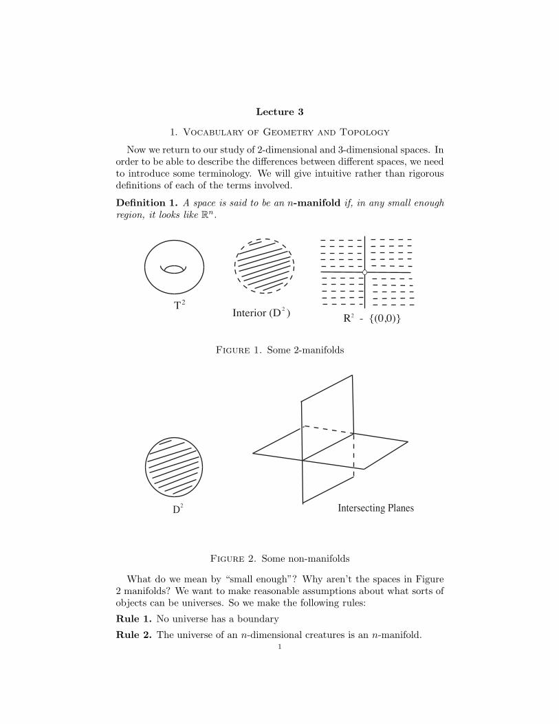
Now we return to our study of 2-dimensional and 3-dimensional spaces. Inorder to be able to describe the differences between different spaces, we needto introduce some terminology. We will give intuitive rather than rigorousdefinitions of each of the terms involved.
Definition 1. A space is said to be an n-manifold if, in any small enough
region, it looks like Rn.
T2
Interior (D )2
R - {(0,0)}2
Figure 1. Some 2-manifolds
D2 Intersecting Planes
Figure 2. Some non-manifolds
What do we mean by “small enough”? Why aren’t the spaces in Figure2 manifolds? We want to make reasonable assumptions about what sorts ofobjects can be universes. So we make the following rules:
Rule 1. No universe has a boundary
Rule 2. The universe of an n-dimensional creatures is an n-manifold.1
2
In fact, Rule 1 follows from Rule 2. How? From Rule 2 we know thatFlatland is a 2-manifold, and our universe is a 3-manifold. We will add morerules later. First we need to introduce some more terminology.
Definition 2. The topology of a manifold is the set of properties of it
which are unchanged by deforming it or cutting it apart and regluing the
same parts together.
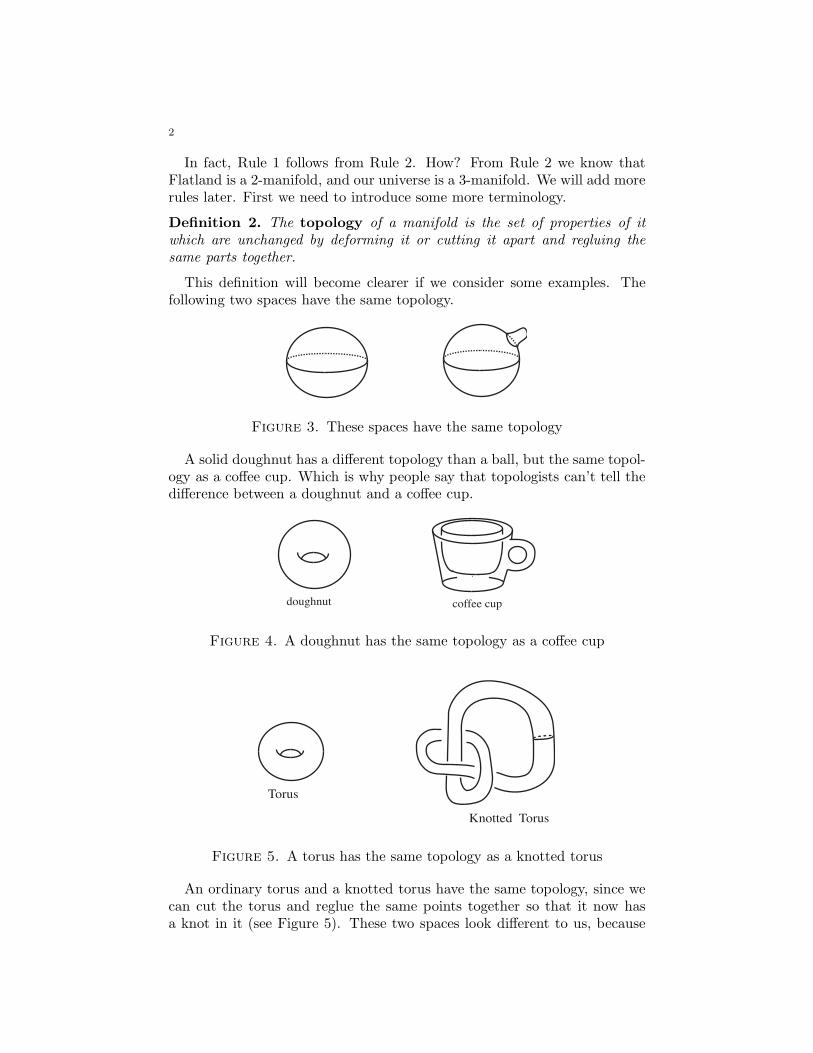
This definition will become clearer if we consider some examples. Thefollowing two spaces have the same topology.
Figure 3. These spaces have the same topology
A solid doughnut has a different topology than a ball, but the same topol-ogy as a coffee cup. Which is why people say that topologists can’t tell thedifference between a doughnut and a coffee cup.
doughnut coffee cup
Figure 4. A doughnut has the same topology as a coffee cup
Torus
Knotted Torus
Figure 5. A torus has the same topology as a knotted torus
An ordinary torus and a knotted torus have the same topology, since wecan cut the torus and reglue the same points together so that it now hasa knot in it (see Figure 5). These two spaces look different to us, because
3
they are situated differently in our space. But their 2-dimensional topologyis actually the same.
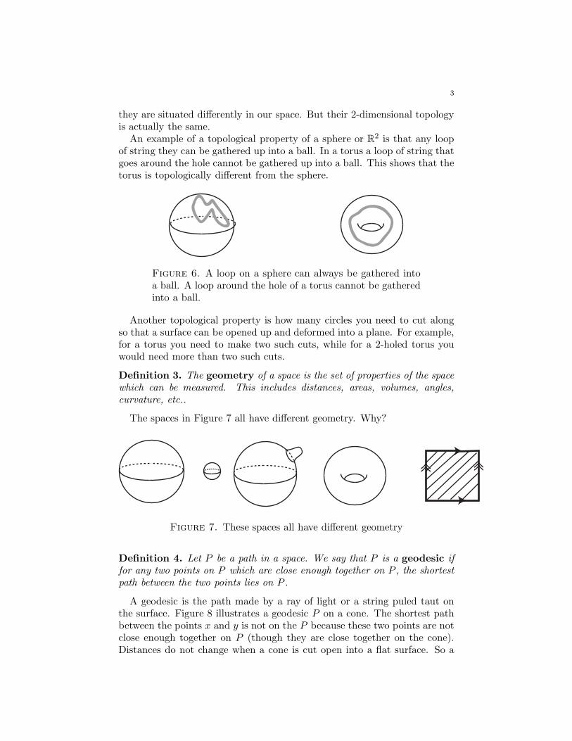
An example of a topological property of a sphere or R2 is that any loop
of string they can be gathered up into a ball. In a torus a loop of string thatgoes around the hole cannot be gathered up into a ball. This shows that thetorus is topologically different from the sphere.
Figure 6. A loop on a sphere can always be gathered intoa ball. A loop around the hole of a torus cannot be gatheredinto a ball.
Another topological property is how many circles you need to cut alongso that a surface can be opened up and deformed into a plane. For example,for a torus you need to make two such cuts, while for a 2-holed torus youwould need more than two such cuts.
Definition 3. The geometry of a space is the set of properties of the space
which can be measured. This includes distances, areas, volumes, angles,
curvature, etc..
The spaces in Figure 7 all have different geometry. Why?
Figure 7. These spaces all have different geometry
Definition 4. Let P be a path in a space. We say that P is a geodesic if
for any two points on P which are close enough together on P , the shortest
path between the two points lies on P .
A geodesic is the path made by a ray of light or a string puled taut onthe surface. Figure 8 illustrates a geodesic P on a cone. The shortest pathbetween the points x and y is not on the P because these two points are notclose enough together on P (though they are close together on the cone).Distances do not change when a cone is cut open into a flat surface. So a
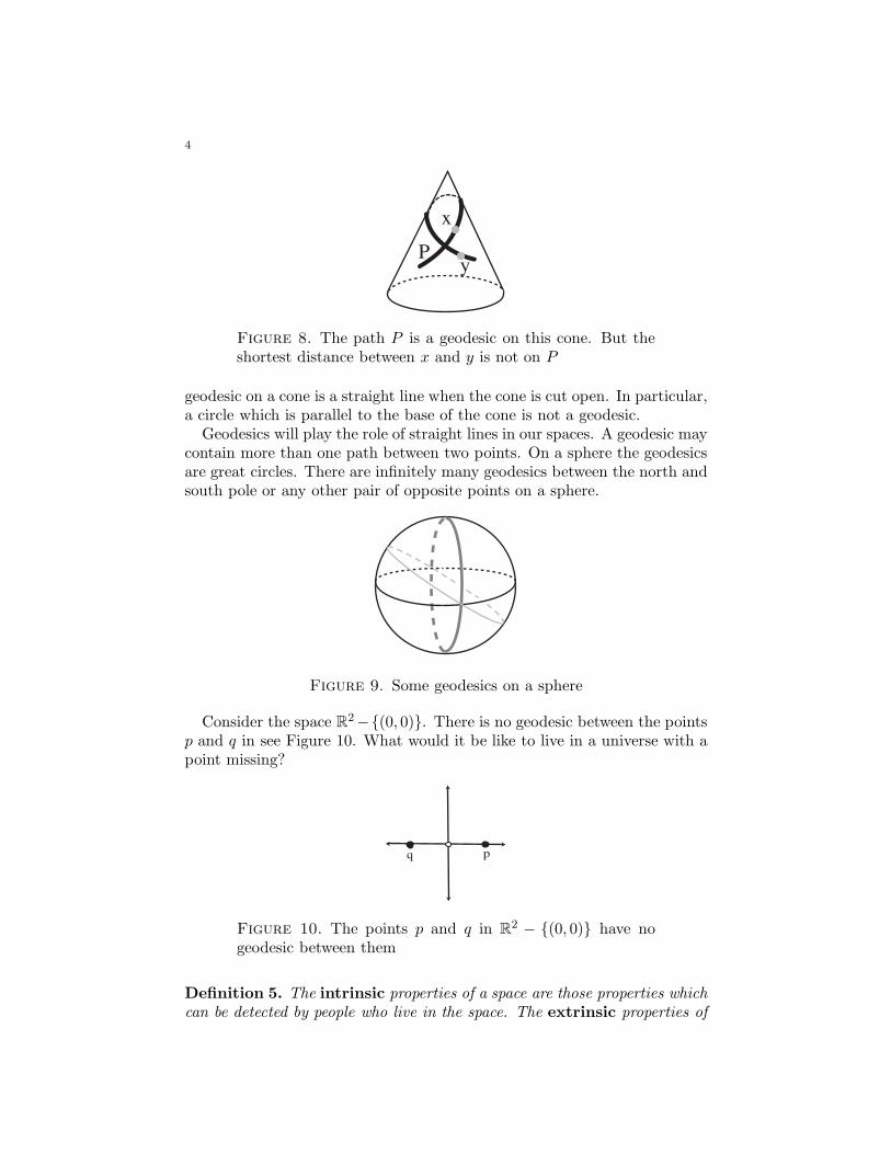
4
P
x
y
Figure 8. The path P is a geodesic on this cone. But theshortest distance between x and y is not on P
geodesic on a cone is a straight line when the cone is cut open. In particular,a circle which is parallel to the base of the cone is not a geodesic.
Geodesics will play the role of straight lines in our spaces. A geodesic maycontain more than one path between two points. On a sphere the geodesicsare great circles. There are infinitely many geodesics between the north andsouth pole or any other pair of opposite points on a sphere.
Figure 9. Some geodesics on a sphere
Consider the space R2−{(0, 0)}. There is no geodesic between the points
p and q in see Figure 10. What would it be like to live in a universe with apoint missing?
q p
Figure 10. The points p and q in R2 − {(0, 0)} have no
geodesic between them
Definition 5. The intrinsic properties of a space are those properties which
can be detected by people who live in the space. The extrinsic properties of
5
a space are those that have to do with how the space is situated in higher
dimensional space. Extrinsic properties cannot be detected by people who live
in the space.
Spaces which are the same extrinsically must be the same intrinsically.This is because if you can tell they are the same from the outside, thenthey must actually be the same. But the converse is not true. For example,an ordinary torus and a knotted torus have the same intrinsic topologybut different extrinsic topology (see Figure 5). Extrinsically, we can tell thedifference between the two tori because one cannot be deformed to the otherin R
3. In general, if one surface can be deformed to another in R3 then they
have the same extrinsic topology. If a surface can be cut apart and re-gluedso that the same points are glued together again then the surfaces have thesame intrinsic topology but not necessarily the same extrinsic topology.
Intrinsic differences can be discussed over the phone by creatures livingin the spaces, extrinsic differences can’t be. For example, the differencebetween a sphere and a torus is intrinsic. But how can it be detected bycreatures living in the space and talking to one another on the phone? Thetopological properties of crumbling up a loop of string and of the number ofcuts needed to make the space planar are both intrinsic properties, becausethey do not have to do with how the space is situated in a higher dimension.
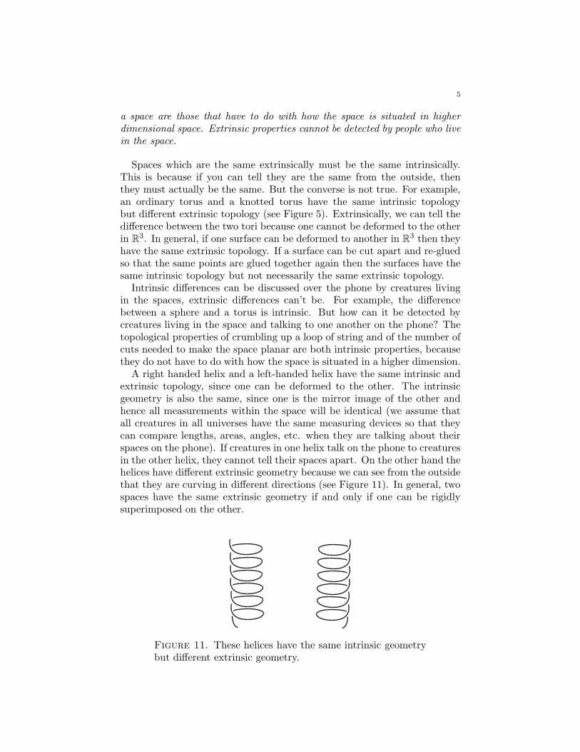
A right handed helix and a left-handed helix have the same intrinsic andextrinsic topology, since one can be deformed to the other. The intrinsicgeometry is also the same, since one is the mirror image of the other andhence all measurements within the space will be identical (we assume thatall creatures in all universes have the same measuring devices so that theycan compare lengths, areas, angles, etc. when they are talking about theirspaces on the phone). If creatures in one helix talk on the phone to creaturesin the other helix, they cannot tell their spaces apart. On the other hand thehelices have different extrinsic geometry because we can see from the outsidethat they are curving in different directions (see Figure 11). In general, twospaces have the same extrinsic geometry if and only if one can be rigidlysuperimposed on the other.
Figure 11. These helices have the same intrinsic geometrybut different extrinsic geometry.
6
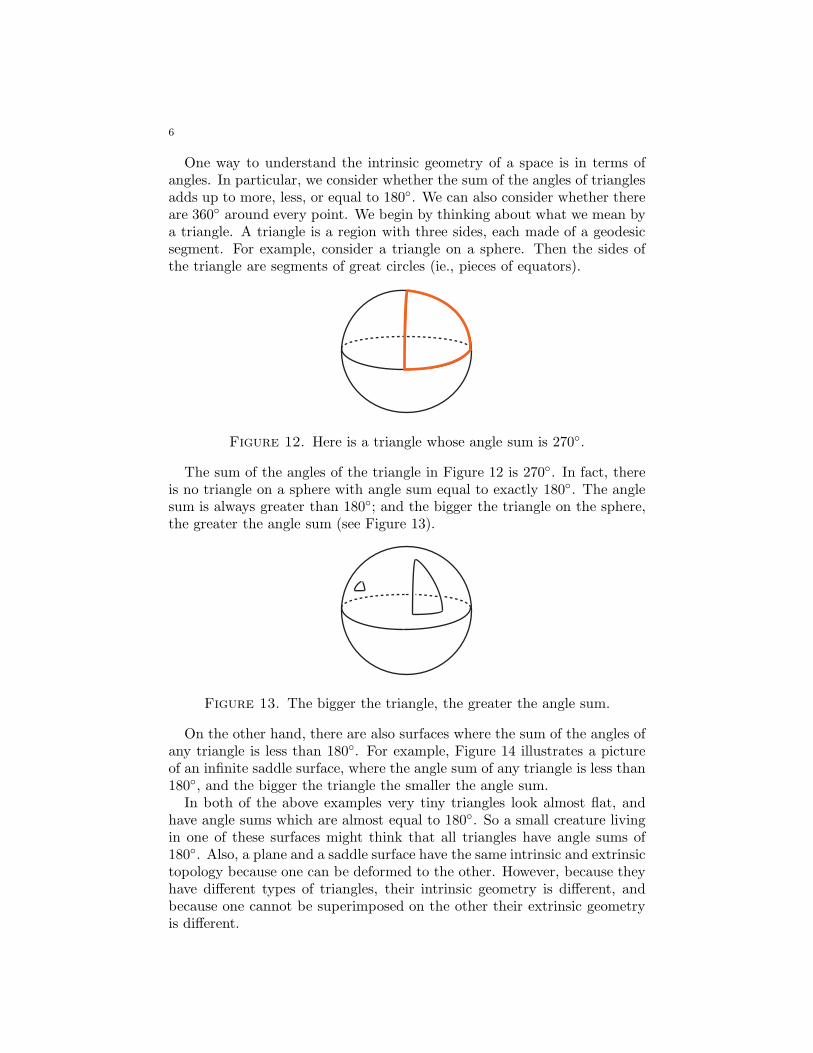
One way to understand the intrinsic geometry of a space is in terms ofangles. In particular, we consider whether the sum of the angles of trianglesadds up to more, less, or equal to 180◦. We can also consider whether thereare 360◦ around every point. We begin by thinking about what we mean bya triangle. A triangle is a region with three sides, each made of a geodesicsegment. For example, consider a triangle on a sphere. Then the sides ofthe triangle are segments of great circles (ie., pieces of equators).
Figure 12. Here is a triangle whose angle sum is 270◦.
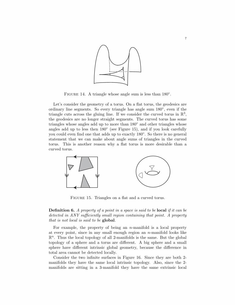
The sum of the angles of the triangle in Figure 12 is 270◦. In fact, thereis no triangle on a sphere with angle sum equal to exactly 180◦. The anglesum is always greater than 180◦; and the bigger the triangle on the sphere,the greater the angle sum (see Figure 13).
Figure 13. The bigger the triangle, the greater the angle sum.
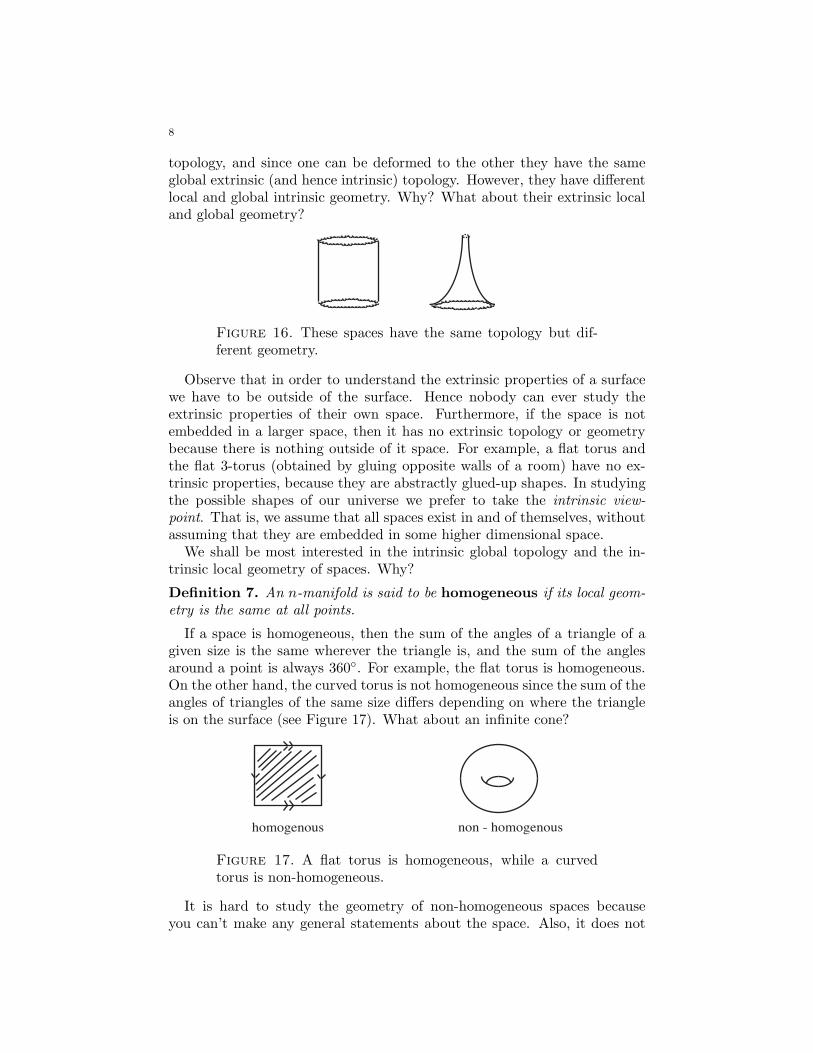
On the other hand, there are also surfaces where the sum of the angles ofany triangle is less than 180◦. For example, Figure 14 illustrates a pictureof an infinite saddle surface, where the angle sum of any triangle is less than180◦, and the bigger the triangle the smaller the angle sum.
In both of the above examples very tiny triangles look almost flat, andhave angle sums which are almost equal to 180◦. So a small creature livingin one of these surfaces might think that all triangles have angle sums of180◦. Also, a plane and a saddle surface have the same intrinsic and extrinsictopology because one can be deformed to the other. However, because theyhave different types of triangles, their intrinsic geometry is different, andbecause one cannot be superimposed on the other their extrinsic geometryis different.
7
Figure 14. A triangle whose angle sum is less than 180◦.
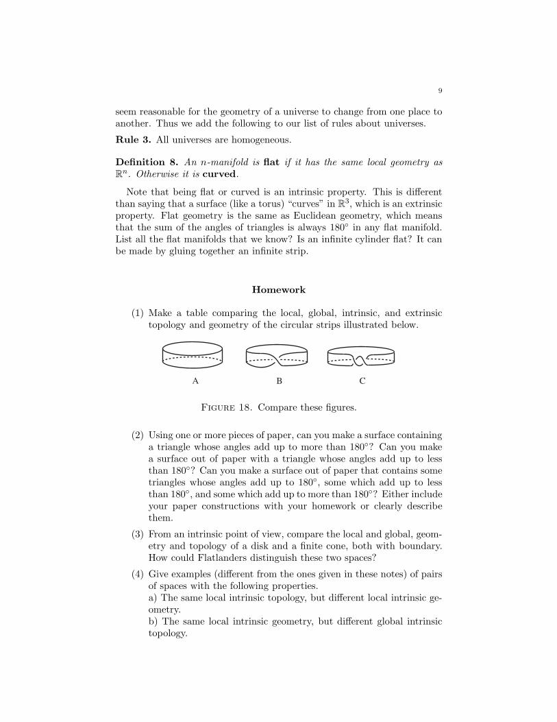
Let’s consider the geometry of a torus. On a flat torus, the geodesics areordinary line segments. So every triangle has angle sum 180◦, even if thetriangle cuts across the gluing line. If we consider the curved torus in R
3,the geodesics are no longer straight segments. The curved torus has sometriangles whose angles add up to more than 180◦ and other triangles whoseangles add up to less then 180◦ (see Figure 15), and if you look carefullyyou could even find one that adds up to exactly 180◦. So there is no generalstatement that we can make about angle sums of triangles in the curvedtorus. This is another reason why a flat torus is more desirable than acurved torus.
Figure 15. Triangles on a flat and a curved torus.
Definition 6. A property of a point in a space is said to be local if it can be
detected in ANY sufficiently small region containing that point. A property
that is not local is said to be global.
For example, the property of being an n-manifold is a local propertyat every point, since in any small enough region an n-manifold looks likeR
n. Thus the local topology of all 2-manifolds is the same. But the globaltopology of a sphere and a torus are different. A big sphere and a smallsphere have different intrinsic global geometry, because the difference intotal area cannot be detected locally.
Consider the two infinite surfaces in Figure 16. Since they are both 2-manifolds they have the same local intrinsic topology. Also, since the 2-manifolds are sitting in a 3-manifold they have the same extrinsic local
8
topology, and since one can be deformed to the other they have the sameglobal extrinsic (and hence intrinsic) topology. However, they have differentlocal and global intrinsic geometry. Why? What about their extrinsic localand global geometry?
Figure 16. These spaces have the same topology but dif-ferent geometry.
Observe that in order to understand the extrinsic properties of a surfacewe have to be outside of the surface. Hence nobody can ever study theextrinsic properties of their own space. Furthermore, if the space is notembedded in a larger space, then it has no extrinsic topology or geometrybecause there is nothing outside of it space. For example, a flat torus andthe flat 3-torus (obtained by gluing opposite walls of a room) have no ex-trinsic properties, because they are abstractly glued-up shapes. In studyingthe possible shapes of our universe we prefer to take the intrinsic view-
point. That is, we assume that all spaces exist in and of themselves, withoutassuming that they are embedded in some higher dimensional space.
We shall be most interested in the intrinsic global topology and the in-trinsic local geometry of spaces. Why?
Definition 7. An n-manifold is said to be homogeneous if its local geom-
etry is the same at all points.
If a space is homogeneous, then the sum of the angles of a triangle of agiven size is the same wherever the triangle is, and the sum of the anglesaround a point is always 360◦. For example, the flat torus is homogeneous.On the other hand, the curved torus is not homogeneous since the sum of theangles of triangles of the same size differs depending on where the triangleis on the surface (see Figure 17). What about an infinite cone?
homogenous non - homogenous
Figure 17. A flat torus is homogeneous, while a curvedtorus is non-homogeneous.
It is hard to study the geometry of non-homogeneous spaces becauseyou can’t make any general statements about the space. Also, it does not
9
seem reasonable for the geometry of a universe to change from one place toanother. Thus we add the following to our list of rules about universes.
Rule 3. All universes are homogeneous.
Definition 8. An n-manifold is flat if it has the same local geometry as
Rn. Otherwise it is curved.
Note that being flat or curved is an intrinsic property. This is differentthan saying that a surface (like a torus) “curves” in R
3, which is an extrinsicproperty. Flat geometry is the same as Euclidean geometry, which meansthat the sum of the angles of triangles is always 180◦ in any flat manifold.List all the flat manifolds that we know? Is an infinite cylinder flat? It canbe made by gluing together an infinite strip.
Homework
(1) Make a table comparing the local, global, intrinsic, and extrinsictopology and geometry of the circular strips illustrated below.
A B C
Figure 18. Compare these figures.
(2) Using one or more pieces of paper, can you make a surface containinga triangle whose angles add up to more than 180◦? Can you makea surface out of paper with a triangle whose angles add up to lessthan 180◦? Can you make a surface out of paper that contains sometriangles whose angles add up to 180◦, some which add up to lessthan 180◦, and some which add up to more than 180◦? Either includeyour paper constructions with your homework or clearly describethem.
(3) From an intrinsic point of view, compare the local and global, geom-etry and topology of a disk and a finite cone, both with boundary.How could Flatlanders distinguish these two spaces?
(4) Give examples (different from the ones given in these notes) of pairsof spaces with the following properties.a) The same local intrinsic topology, but different local intrinsic ge-ometry.b) The same local intrinsic geometry, but different global intrinsictopology.
10
c) The same global intrinsic topology, but different global extrinsictopology.d) The same local intrinsic geometry, but different global intrinsicgeometry.e) The same global intrinsic geometry, but different global extrinsicgeometry.
(5) Is the surface of a cube homogeneous? Why or why not?
(6) Compare the local and global geometry and topology of a 3-torusmade from a rectangular room and one made from a cubical room.
(7) For each of the surfaces listed below, state one or more intrinsictopological and/or geometric properties that enables you to distin-guish that surface from ALL of the other surfaces in the list. Statewhether each property you refer to is topological or geometric.
• a plane• a flat torus• a flat Klein bottle• a sphere• the surface bounding a cube
Lecture 4
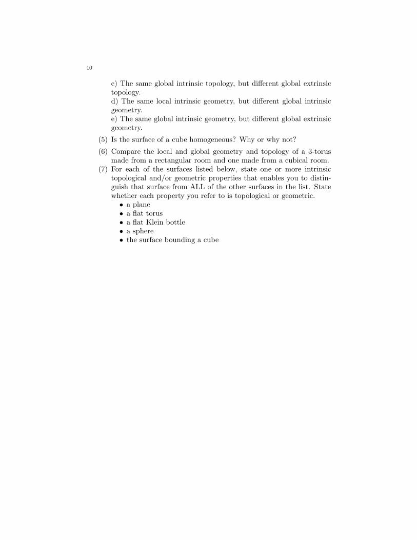
1. Orientability
We have seen that if a person is turned over in a higher dimension thenthe person will become his/her mirror image. It is also possible to becomeyour mirror image without even leaving your space. Here is a picture ofa Mobius strip. You can see that A. Square gets reversed when he walkscompletely around the strip.
finish start
Figure 1. A. Square walks around a Mobius strip.
Definition 1. Any path that you can walk along and have your orientation
reversed is called an orientation reversing path. A space is said to be
non-orientable if it contains an orientation reversing path. Otherwise it
is said to be orientable.
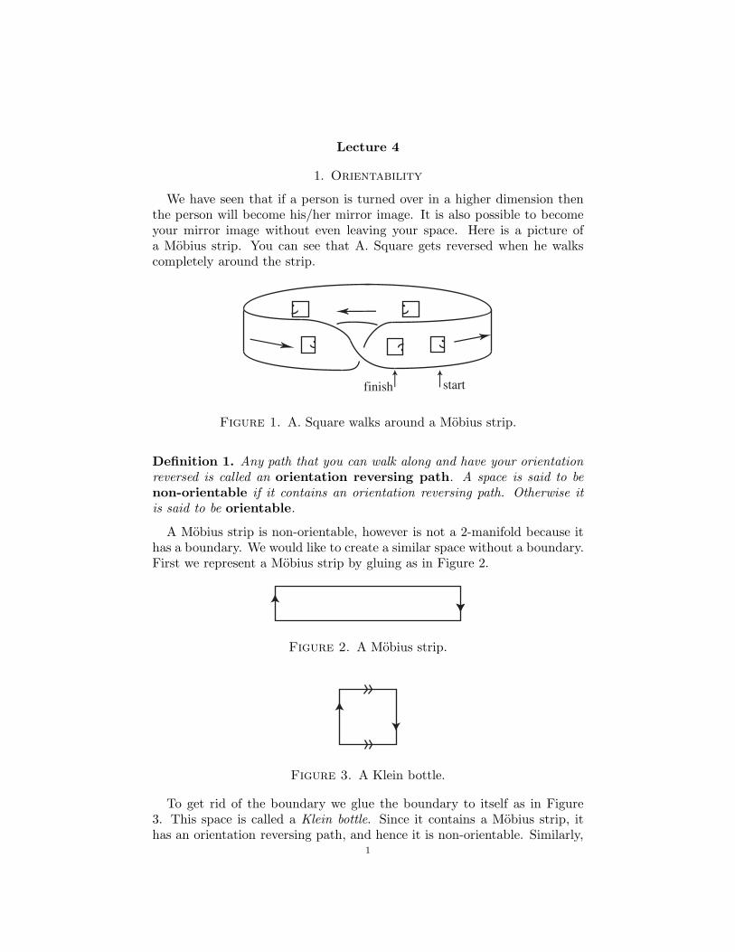
A Mobius strip is non-orientable, however is not a 2-manifold because ithas a boundary. We would like to create a similar space without a boundary.First we represent a Mobius strip by gluing as in Figure 2.
Figure 2. A Mobius strip.
Figure 3. A Klein bottle.
To get rid of the boundary we glue the boundary to itself as in Figure3. This space is called a Klein bottle. Since it contains a Mobius strip, ithas an orientation reversing path, and hence it is non-orientable. Similarly,
1
2
we can create a 3-dimensional Klein bottle by gluing a room with the frontwall glued to the back wall and ceiling glued to the floor as in the 3-torus,but with the side walls glued together with a flip so that the back of the leftwall is glued to the front of the right wall. What would happen to me if Iwalked through the left wall?
This is an interesting space to study. But it doesn’t seem likely that peoplecan actually take a trip around their universe and come back reversed. Sowe make another rule about real universes.
Rule 4. All universes are orientable.
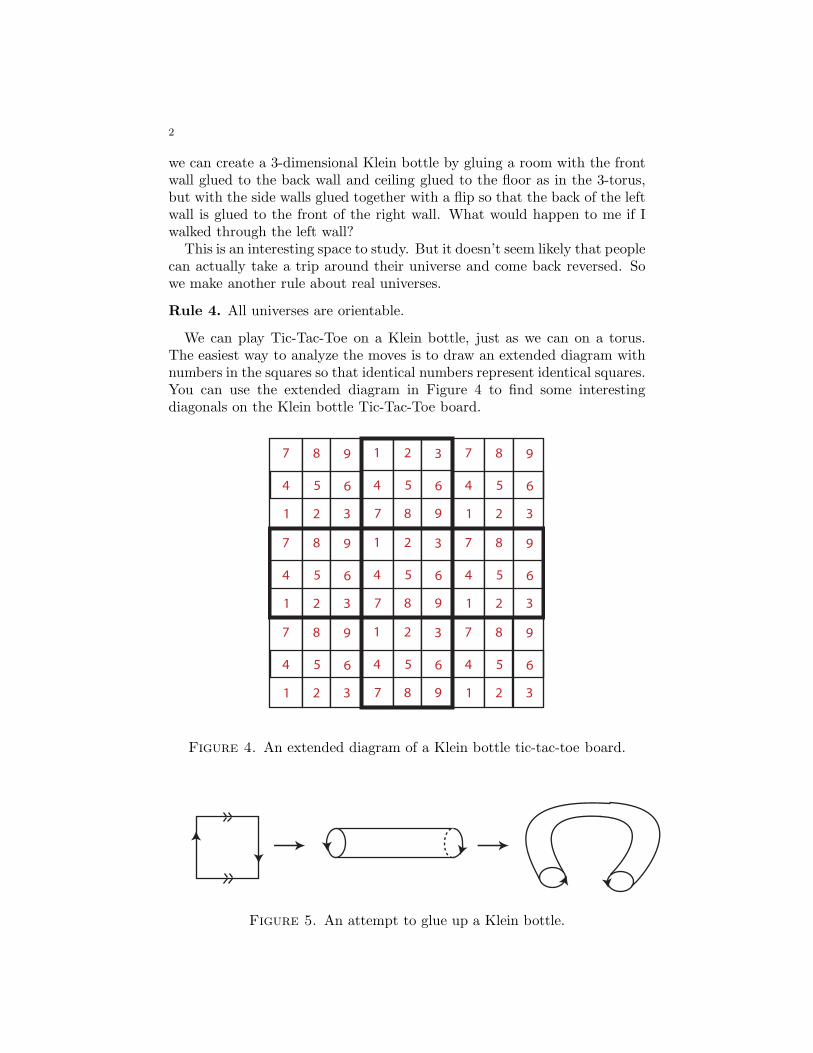
We can play Tic-Tac-Toe on a Klein bottle, just as we can on a torus.The easiest way to analyze the moves is to draw an extended diagram withnumbers in the squares so that identical numbers represent identical squares.You can use the extended diagram in Figure 4 to find some interestingdiagonals on the Klein bottle Tic-Tac-Toe board.
7 8 9
1 2 3
4 5 6
1 2 3
7 8 9
4 5 6
7 8 9
1 2 3
4 5 6
7 8 9
1 2 3
4 5 6
1 2 3
7 8 9
4 5 6
7 8 9
1 2 3
4 5 6
7 8 9
1 2 3
4 5 6
1 2 3
7 8 9
4 5 6
7 8 9
1 2 3
4 5 6
Figure 4. An extended diagram of a Klein bottle tic-tac-toe board.
Figure 5. An attempt to glue up a Klein bottle.
3
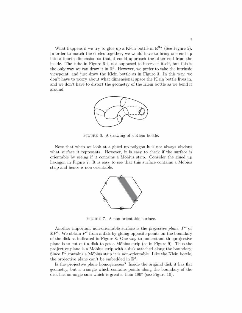
What happens if we try to glue up a Klein bottle in R3? (See Figure 5).
In order to match the circles together, we would have to bring one end upinto a fourth dimension so that it could approach the other end from theinside. The tube in Figure 6 is not supposed to intersect itself, but this isthe only way we can draw it in R
3. However, we prefer to take the intrinsicviewpoint, and just draw the Klein bottle as in Figure 3. In this way, wedon’t have to worry about what dimensional space the Klein bottle lives in,and we don’t have to distort the geometry of the Klein bottle as we bend itaround.
Figure 6. A drawing of a Klein bottle.
Note that when we look at a glued up polygon it is not always obviouswhat surface it represents. However, it is easy to check if the surface isorientable by seeing if it contains a Mobius strip. Consider the glued uphexagon in Figure 7. It is easy to see that this surface contains a Mobiusstrip and hence is non-orientable.
Figure 7. A non-orientable surface.
Another important non-orientable surface is the projective plane, P 2 orRP 2. We obtain P 2 from a disk by gluing opposite points on the boundaryof the disk as indicated in Figure 8. One way to understand th eprojectiveplane is to cut out a disk to get a Mobius strip (as in Figure 9). Thus theprojective plane is a Mobius strip with a disk attached along the boundary.Since P 2 contains a Mobius strip it is non-orientable. Like the Klein bottle,the projective plane can’t be embedded in R
3.Is the projective plane homogeneous? Inside the original disk it has flat
geometry, but a triangle which contains points along the boundary of thedisk has an angle sum which is greater than 180◦ (see Figure 10).
4
Figure 8. A projective plane.
Figure 9. A projective plane can be cut up into a Mobiusstrip and a disk.
Figure 10. This triangle has angle sum greater than 180◦.
To avoid this problem we choose to make P 2 out of a glued-up hemisphererather than a glued up disk (see Figure 11). When we do this, the localgeometry of P 2 is the same as the local geometry of a sphere, where theangle sum of a triangle is always more than 180◦. This makes the projectiveplane homogeneous. We prefer this construction of the projective plane justas we prefer the flat torus to the curved torus.
Figure 11. A homogeneous projective plane.
5
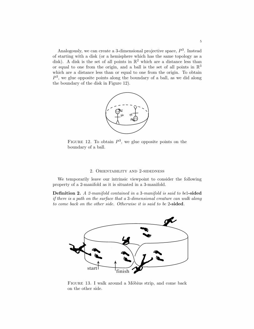
Analogously, we can create a 3-dimensional projective space, P 3. Insteadof starting with a disk (or a hemisphere which has the same topology as adisk). A disk is the set of all points in R
2 which are a distance less thanor equal to one from the origin, and a ball is the set of all points in R
3
which are a distance less than or equal to one from the origin. To obtainP 3, we glue opposite points along the boundary of a ball, as we did alongthe boundary of the disk in Figure 12).
Figure 12. To obtain P 3, we glue opposite points on theboundary of a ball.
2. Orientability and 2-sidedness
We temporarily leave our intrinsic viewpoint to consider the followingproperty of a 2-manifold as it is situated in a 3-manifold.
Definition 2. A 2-manifold contained in a 3-manifold is said to be1-sided
if there is a path on the surface that a 3-dimensional creature can walk along
to come back on the other side. Otherwise it is said to be 2-sided.
finishstart
Figure 13. I walk around a Mobius strip, and come backon the other side.
6
Observe that 1-sidedness is an extrinsic property of a surface in a 3-manifold because it has to do with how the surface is embedded. Let’sconsider a Mobius strip embedded in R
3. Suppose I walk around a Mobiusstrip. My footprints will return to where they started but I will be on theother side of the Mobius strip (see Figure 13). Thus this embedding of aMobius strip in R
3 is 1-sided. On the other hand, if I stand on a cylinderand walk around in a circle, I will never come back on the other side. So acylinder in R
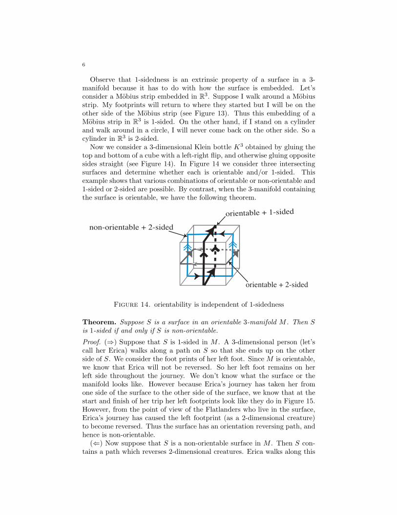
3 is 2-sided.Now we consider a 3-dimensional Klein bottle K3 obtained by gluing the
top and bottom of a cube with a left-right flip, and otherwise gluing oppositesides straight (see Figure 14). In Figure 14 we consider three intersectingsurfaces and determine whether each is orientable and/or 1-sided. Thisexample shows that various combinations of orientable or non-orientable and1-sided or 2-sided are possible. By contrast, when the 3-manifold containingthe surface is orientable, we have the following theorem.
orientable + 1-sided
non-orientable + 2-sided
orientable + 2-sided
Figure 14. orientability is independent of 1-sidedness
Theorem. Suppose S is a surface in an orientable 3-manifold M . Then S
is 1-sided if and only if S is non-orientable.
Proof. (⇒) Suppose that S is 1-sided in M . A 3-dimensional person (let’scall her Erica) walks along a path on S so that she ends up on the otherside of S. We consider the foot prints of her left foot. Since M is orientable,we know that Erica will not be reversed. So her left foot remains on herleft side throughout the journey. We don’t know what the surface or themanifold looks like. However because Erica’s journey has taken her fromone side of the surface to the other side of the surface, we know that at thestart and finish of her trip her left footprints look like they do in Figure 15.However, from the point of view of the Flatlanders who live in the surface,Erica’s journey has caused the left footprint (as a 2-dimensional creature)to become reversed. Thus the surface has an orientation reversing path, andhence is non-orientable.
(⇐) Now suppose that S is a non-orientable surface in M . Then S con-tains a path which reverses 2-dimensional creatures. Erica walks along this
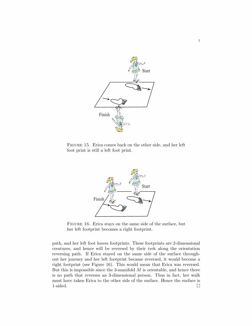
7
Finish
Start
Figure 15. Erica comes back on the other side, and her leftfoot print is still a left foot print.
Finish
Start
Figure 16. Erica stays on the same side of the surface, buther left footprint becomes a right footprint.
path, and her left foot leaves footprints. These footprints are 2-dimensionalcreatures, and hence will be reversed by their trek along the orientationreversing path. If Erica stayed on the same side of the surface through-out her journey and her left footprint became reversed, it would become aright footprint (see Figure 16). This would mean that Erica was reversed.But this is impossible since the 3-manifold M is orientable, and hence thereis no path that reverses an 3-dimensional person. Thus in fact, her walkmust have taken Erica to the other side of the surface. Hence the surface is1-sided. �
8
Homework
(1) Does a 3-dimensional Klein bottle necessarily contain a 2-dimensionalKlein bottle? If so, where? And how many Klein bottles does it con-tain?
(2) Carefully explain whether or not a 3-dimensional projective space isorientable. Draw a picture to illustrate your argument.
(3) A tube connecting two spaces is sometimes called an Einstein-Rosen
bridge. What does an Einstein-Rosen bridge look like to Flatlanders?
(4) Suppose two parallel planes are connected by an Einstein-Rosenbridge. How do the squares in one plane appear to the squaresin the other plane? If the squares in the two planes are oriented in aparallel way, do the squares in one plane appear to the squares in theother plane to be reversed? Is the space orientable? If two planesare connected by two Einstein-Rosen bridges is the space orientable?
(5) Describe a 3-dimensional Einstein-Rosen bridge. Suppose there is a3-dimensional Einstein-Rosen bridge attaching one R
3 to a parallelR
3. Is the space orientable?
(6) Suppose A. Square lives on a Mobius strip. How does he see himself?Does he appear to be reversed? Suppose he stands still and watcheshis friend B. Triangle walk around and around the strip. Just as hisfriend is passing him after going once around the strip, A. Squarelooks at all the copies of his friend. Which, if any, of them willappear to be reversed? Draw an extended picture of a Mobius stripcontaining A. Square and B. Triangle.
(7) Suppose you live in a 3-dimensional Klein bottle. Are your imagesreversed or not? If you watch a friend walk through the wall of a3-dimensional Klein bottle, and look at all the images of her, which(if any) of them will be reversed?
(8) What is a good definition of left and right? Suppose that a person’sback and front were identical, with feet and hands facing both di-rections and a face on both sides of her head. Now does the personhave a distinct right and a left side?
(9) Why do we say a mirror reverses your left and right side, but notyour head and feet? What if you were lying down or the mirror wason the ceiling?
(10) Suppose A. Square lives alone in a small Klein bottle and each sideof A. Square is colored a different color. Imagine that he can see inall directions, and his brain can determine relative distances. Drawan extended picture of A. Square’s space
9
(11) List all three-in-a-row diagonals in Klein bottle tic-tac-toe?
(12) How many inequivalent first moves and second moves are there inKlein bottle tic-tac-toe? Recall that two moves are equivalent if thestrategy for the rest of the game is analogous. This does not justmean that the NUMBER of ways to win is the same. Note thatif there is a symmetry of the board then corresponding moves areequivalent.
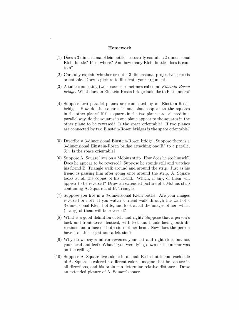
(13) Will the first player necessarily win Klein bottle tic-tac-toe assumingoptimal play? If so, list each of the moves the first player shouldmake in order to win.
(14) Discuss the sidedness and orientability of the surfaces in the 3-manifolds in the Figure below.
a) b)
c) d)
(15) For each of the spaces the Figure above, draw a surface perpendicularto the given one and determine its sidedness and orientability.
Lecture 5
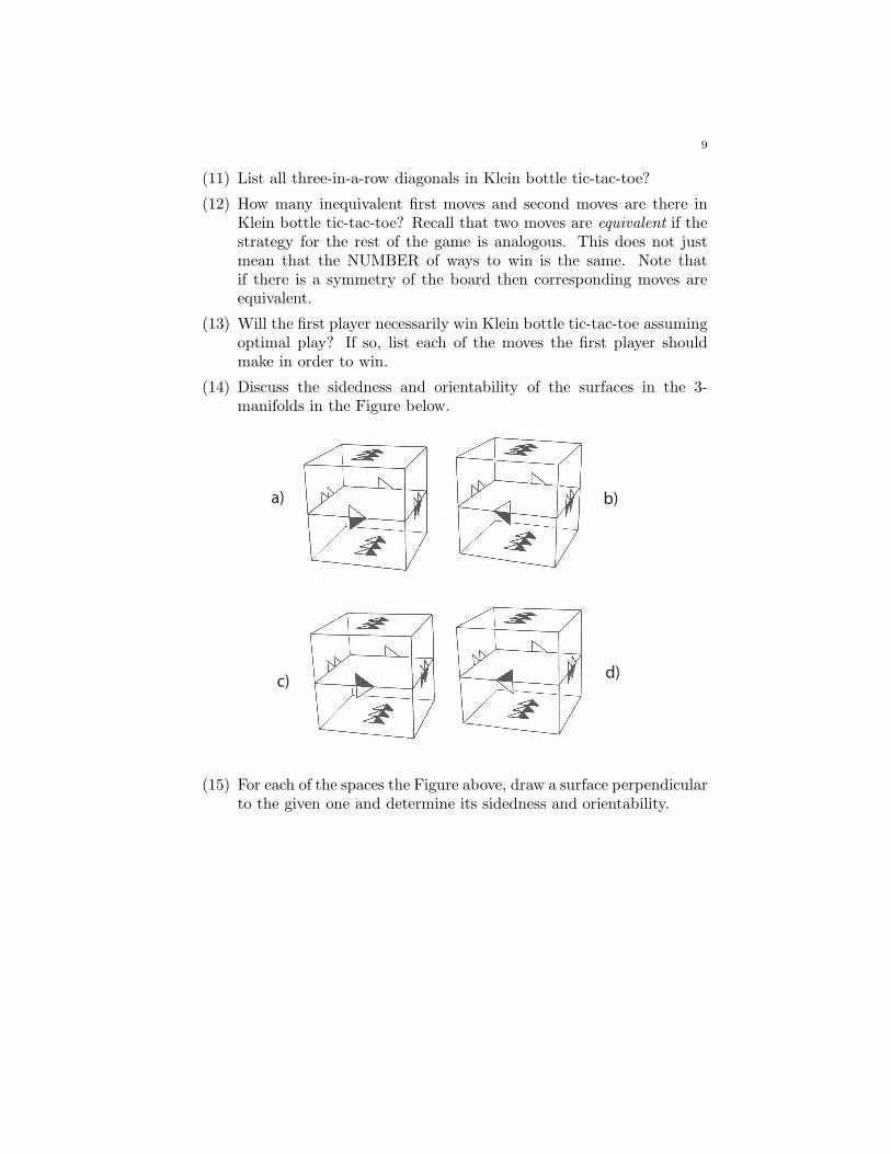
1. Connected Sums
In a homework problem we saw that two spaces can be joined togetherwith an Einstein-Rosen bridge to create a new space. Whether the tube waslong or short would have no effect on the topology. The tube was just a wayto get from one of the spaces to the other. Now we will shorten the tubeuntil it has no length at all, and it just becomes a circle. We will use thefollowing method of joining spaces instead of using Einstein-Rosen bridges.
Definition 1. Let A and B be surfaces. The connected sum, A#B, is
the surface obtained from A and B by removing a disk from each and gluing
the remaining surfaces together along their boundary.
For example, Figure 1 illustrates the connected sum of two tori, denotedby T 2#T 2 = 2T 2.
# = =
Figure 1. The connected sum of two tori.
For the moment we shall focus on the topology of connected sums andignore the geometry. Thus we can slide the disk that will be removed aroundon A and B, and we can deform A and B to our heart’s delight. Considerthe connected sum of a torus T 2 and a sphere S2. As we can see from Figure2, T 2#S2 = T 2.
#
# = =
Figure 2. The connected sum of a torus and a sphere is a torus.
∪ =
Figure 3. The connected sum of two projective planes.
1
2
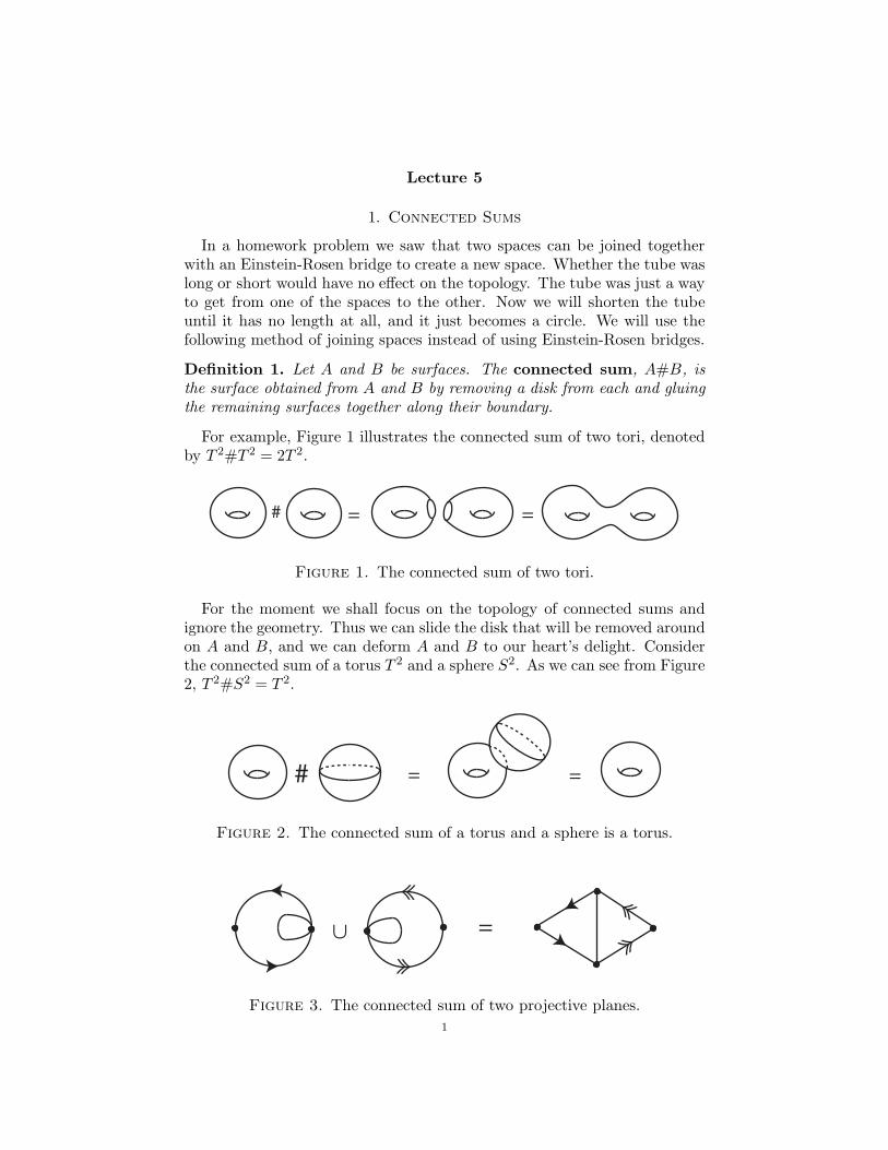
Now consider the connected sum of two projective planes, P 2#P 2 = 2P 2
(see Figure 3) . To understand this surface we cut the surface apart and glueit together differently, keeping track of the original gluings. We see from thesequence of pictures in Figure 4 that 2P 2 is a Klein bottle.
= = =
Figure 4. The connected sum of two projective planes is aKlein bottle.
Figure 5 gives us an idea of how we can represent n projective planes asa single glued up polygon. How many sides does a glued up polygon needto have to represent nP 2 in this way? Similarly we can represent 2T 2 as inFigure 6. How many sides does a glued up polygon need to represent nT 2?
3P2
2P2
Figure 5. The connected sum of two and three projective planes.
2T 2T
∪∪ = =
Figure 6. The connected sum of two tori.
The following is an important result in topology, which we won’t prove.
3
Theorem. (The Classification of Surfaces) Every 2-manifold with fi-
nite area is the connected sum of some number of tori and some number of
projective planes, including S2 = 0T 2#0P 2.
This theorem says that every finite surface has the form nT 2#mP 2. Forhomework you will prove that T 2#P 2 = 3P 2. From this equation and theClassification of Surfaces you will then prove that every finite 2-manifoldhas the form nT 2 or nP 2 (where n may be zero). This means we can getevery surface without having to mix tori with projective planes. It followsthat every orientable surface has the form nT 2 with n ≥ 0, and every non-orientable surface has the form nP 2 with n ≥ 1.
Example. 2T 2#P 2 = T 2#(T 2#P 2) = T 2#3P 2 = (T 2#P 2)#2P 2 =3P 2#2P 2 = 5P 2.
The idea of connected sums can also be extended to 3 dimensions.
Definition 2. Let A and B be 3-manifolds. Then A#B is obtained by
removing an open ball from each of A and B and gluing the remaining spaces
together along their boundaries.
Let T 3 denote the 3-torus, let P 3 denote the 3-dimensional projectiveplane, and let K3 denote the 3-dimensional Klein bottle. We can use con-nected sums to create infinitely many 3-manifolds. For example, T 3#T 3,T 3#P 3, or T 3#K3. How can we visualize these spaces?
2. Topological and Geometric Products
So far, the only finite volume 3-manifolds that we have seen are T 3, P 3,K3 and connected sums of these. Now we introduce products as anotherway to create new spaces.
Definition 3. Let X and Y be sets. Define X×Y = {(x, y)|x ∈ X, y ∈ Y }.
Thus every point in X × Y can be expressed uniquely as (x, y). Forexample, we are familiar with R
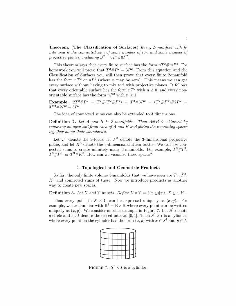
2 = R×R where every point can be writtenuniquely as (x, y). We consider another example in Figure 7. Let S1 denotea circle and let I denote the closed interval [0, 1]. Then S1 × I is a cylinder,where every point on the cylinder has the form (x, y) with x ∈ S1 and y ∈ I.
Figure 7. S1 × I is a cylinder.
4
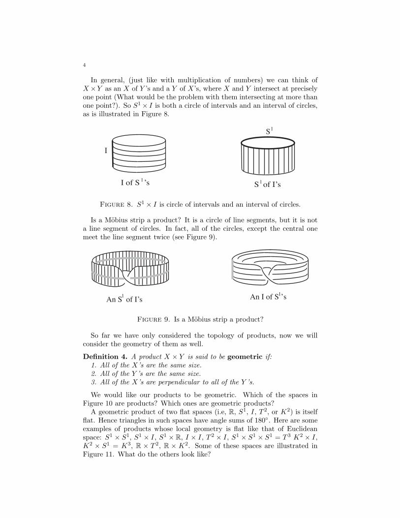
In general, (just like with multiplication of numbers) we can think ofX ×Y as an X of Y ’s and a Y of X’s, where X and Y intersect at preciselyone point (What would be the problem with them intersecting at more thanone point?). So S1 × I is both a circle of intervals and an interval of circles,as is illustrated in Figure 8.
I of S ’s S of I’s1 1
I
S1
Figure 8. S1 × I is circle of intervals and an interval of circles.
Is a Mobius strip a product? It is a circle of line segments, but it is nota line segment of circles. In fact, all of the circles, except the central onemeet the line segment twice (see Figure 9).
1 1
An S of I’s An I of S s
Figure 9. Is a Mobius strip a product?
So far we have only considered the topology of products, now we willconsider the geometry of them as well.
Definition 4. A product X × Y is said to be geometric if:
1. All of the X’s are the same size.
2. All of the Y ’s are the same size.
3. All of the X’s are perpendicular to all of the Y ’s.
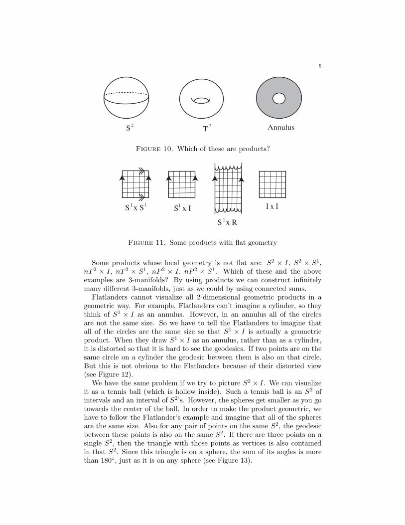
We would like our products to be geometric. Which of the spaces inFigure 10 are products? Which ones are geometric products?
A geometric product of two flat spaces (i.e, R, S1, I, T 2, or K2) is itselfflat. Hence triangles in such spaces have angle sums of 180◦. Here are someexamples of products whose local geometry is flat like that of Euclideanspace: S1 × S1, S1 × I, S1 × R, I × I, T 2 × I, S1 × S1 × S1 = T 3 K2 × I,K2 × S1 = K3, R × T 2, R × K2. Some of these spaces are illustrated inFigure 11. What do the others look like?
5
S2
T2 Annulus
Figure 10. Which of these are products?
I x IS x S1 1S x I
1
S x R1
Figure 11. Some products with flat geometry
Some products whose local geometry is not flat are: S2 × I, S2 × S1,nT 2 × I, nT 2 × S1, nP 2 × I, nP 2 × S1. Which of these and the aboveexamples are 3-manifolds? By using products we can construct infinitelymany different 3-manifolds, just as we could by using connected sums.
Flatlanders cannot visualize all 2-dimensional geometric products in ageometric way. For example, Flatlanders can’t imagine a cylinder, so theythink of S1 × I as an annulus. However, in an annulus all of the circlesare not the same size. So we have to tell the Flatlanders to imagine thatall of the circles are the same size so that S1 × I is actually a geometricproduct. When they draw S1 × I as an annulus, rather than as a cylinder,it is distorted so that it is hard to see the geodesics. If two points are on thesame circle on a cylinder the geodesic between them is also on that circle.But this is not obvious to the Flatlanders because of their distorted view(see Figure 12).
We have the same problem if we try to picture S2 × I. We can visualizeit as a tennis ball (which is hollow inside). Such a tennis ball is an S2 ofintervals and an interval of S2’s. However, the spheres get smaller as you gotowards the center of the ball. In order to make the product geometric, wehave to follow the Flatlander’s example and imagine that all of the spheresare the same size. Also for any pair of points on the same S2, the geodesicbetween these points is also on the same S2. If there are three points on asingle S2, then the triangle with those points as vertices is also containedin that S2. Since this triangle is on a sphere, the sum of its angles is morethan 180◦, just as it is on any sphere (see Figure 13).
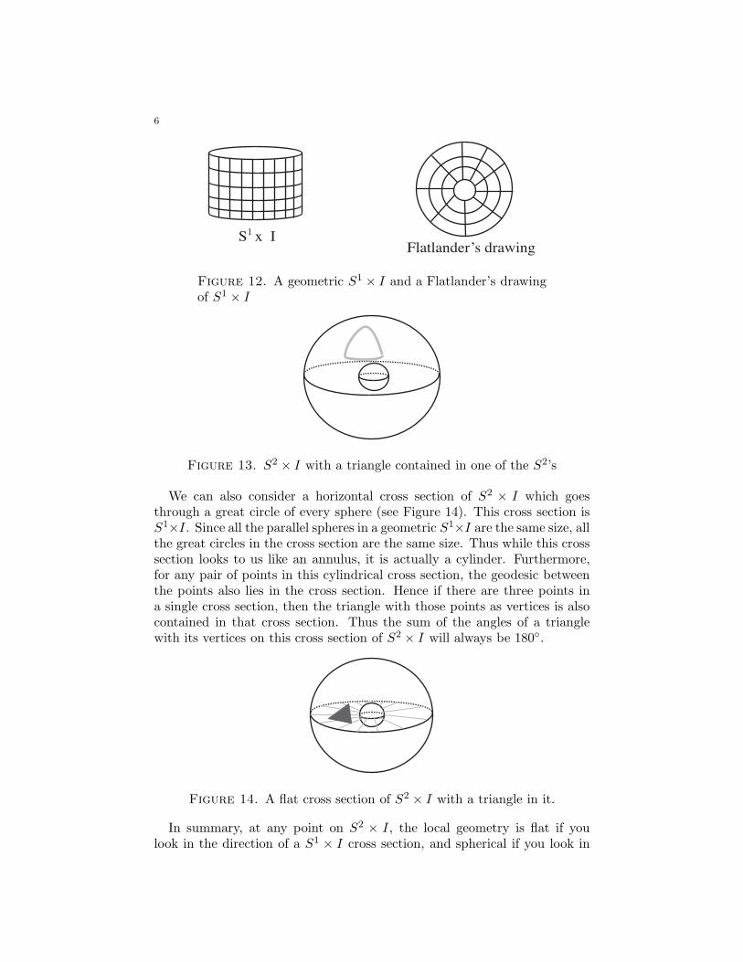
6
S x IFlatlander’s drawing
1
Figure 12. A geometric S1 × I and a Flatlander’s drawingof S1 × I
Figure 13. S2 × I with a triangle contained in one of the S2’s
We can also consider a horizontal cross section of S2 × I which goesthrough a great circle of every sphere (see Figure 14). This cross section isS1×I. Since all the parallel spheres in a geometric S1×I are the same size, allthe great circles in the cross section are the same size. Thus while this crosssection looks to us like an annulus, it is actually a cylinder. Furthermore,for any pair of points in this cylindrical cross section, the geodesic betweenthe points also lies in the cross section. Hence if there are three points ina single cross section, then the triangle with those points as vertices is alsocontained in that cross section. Thus the sum of the angles of a trianglewith its vertices on this cross section of S2 × I will always be 180◦.
Figure 14. A flat cross section of S2 × I with a triangle in it.
In summary, at any point on S2 × I, the local geometry is flat if youlook in the direction of a S1 × I cross section, and spherical if you look in
7
the direction of a single S2. So the geometry at a point depends on whichdirection you are looking.
Definition 5. A space is said to be isotropic if when you are standing at
any point, the local geometry in a small enough region is the same in all
directions.
We have just seen that S2 × I is not isotropic. All of the other spaces wehave considered thus far are isotropic. On the other hand, S2 × I is not amanifold because it has boundary. We would like to make a manifold whoselocal geometry is like that of S2 × I. The boundary of S2 × I consists of aninner sphere and an outer sphere. To get rid of both boundary componentswe glue these two spheres together. Thus each interval, I, in the productnow becomes a circle, S1. In this way, we obtain the 3-manifold S2 × S1.We have to glue the inner and outer spheres together abstractly, since itcannot be done in R
3. Hence S2 ×S1 is a 3-manifold which is homogeneousbut not isotropic.
Homework
(1) Is the connected sum operation commutative? Is it associative? Dosurfaces have inverses with respect to the operation #?
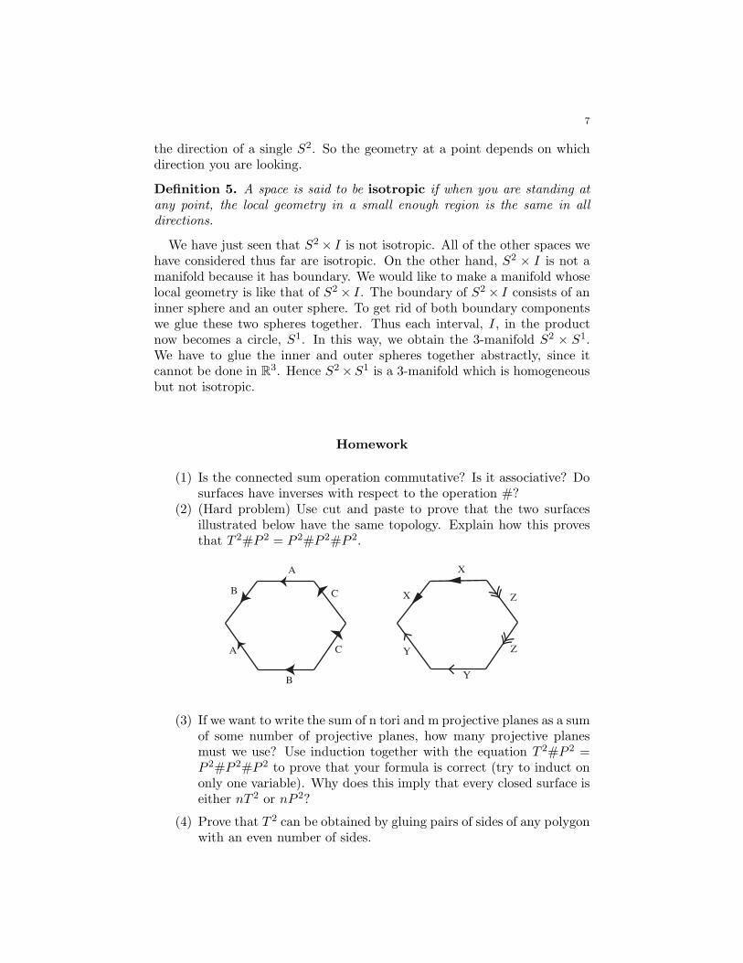
(2) (Hard problem) Use cut and paste to prove that the two surfacesillustrated below have the same topology. Explain how this provesthat T 2#P 2 = P 2#P 2#P 2.
X
Y
Y
Z
Z
A
B
A
B
C
C X
(3) If we want to write the sum of n tori and m projective planes as a sumof some number of projective planes, how many projective planesmust we use? Use induction together with the equation T 2#P 2 =P 2#P 2#P 2 to prove that your formula is correct (try to induct ononly one variable). Why does this imply that every closed surface iseither nT 2 or nP 2?
(4) Prove that T 2 can be obtained by gluing pairs of sides of any polygonwith an even number of sides.
8
(5) Suppose that Flatland is a non-trivial connected sum. How could A.Square detect it topologically? Suppose our universe is a non-trivialconnected sum. How could we detect it topologically?
(6) Find a manifold other than S2 × S1 which is homogeneous but notisotropic?
(7) Find a manifold that is isotropic but not homogeneous?
(8) Suppose that we lived in a universe that we knew was one of S2×S1,P 2×S1, or T 3. How could we tell the difference between these threespaces?
(9) Is the product operation distributive over the connected sum opera-tion? That is, is A × (B#C) = (A × B)#(A × C)?
Lecture 6
1. Flat manifolds
Recall the following definition:
Definition 1. A flat manifold is a homogeneous space whose local geom-etry is Euclidean (i.e., the sum of the angles of every triangle is 180◦).
So far the flat manifolds we have seen are T 2, K2, T 3, K3, R1, R
2, R3,
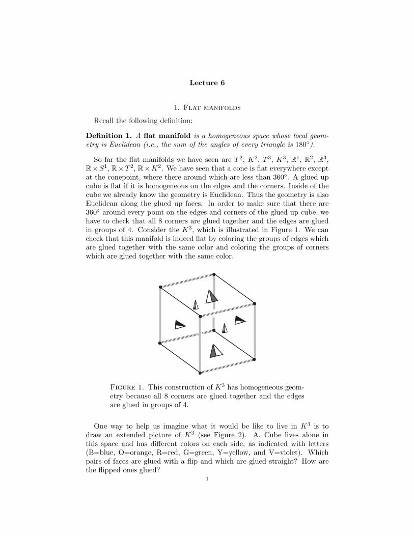
R×S1, R×T 2, R×K2. We have seen that a cone is flat everywhere exceptat the conepoint, where there around which are less than 360◦. A glued upcube is flat if it is homogeneous on the edges and the corners. Inside of thecube we already know the geometry is Euclidean. Thus the geometry is alsoEuclidean along the glued up faces. In order to make sure that there are360◦ around every point on the edges and corners of the glued up cube, wehave to check that all 8 corners are glued together and the edges are gluedin groups of 4. Consider the K3, which is illustrated in Figure 1. We cancheck that this manifold is indeed flat by coloring the groups of edges whichare glued together with the same color and coloring the groups of cornerswhich are glued together with the same color.
Figure 1. This construction of K3 has homogeneous geom-etry because all 8 corners are glued together and the edgesare glued in groups of 4.
One way to help us imagine what it would be like to live in K3 is todraw an extended picture of K3 (see Figure 2). A. Cube lives alone inthis space and has different colors on each side, as indicated with letters(B=blue, O=orange, R=red, G=green, Y=yellow, and V=violet). Whichpairs of faces are glued with a flip and which are glued straight? How arethe flipped ones glued?
1
2
B
B B B B
B
B B
B
B B
BB B B
B
BB
B B B B
BB B
BB
R
R
R
R
G
G
G
R
G
G
G
G
B
B B
B
Y Y
R
R
R
Y YY Y
G
G
G
B
Y Y
V V
V V VV
V V
R
R
Y Y
G
G
R
R
G
Figure 2. An extended diagram of K3 with A. Cube in it.
2. Turn Manifolds
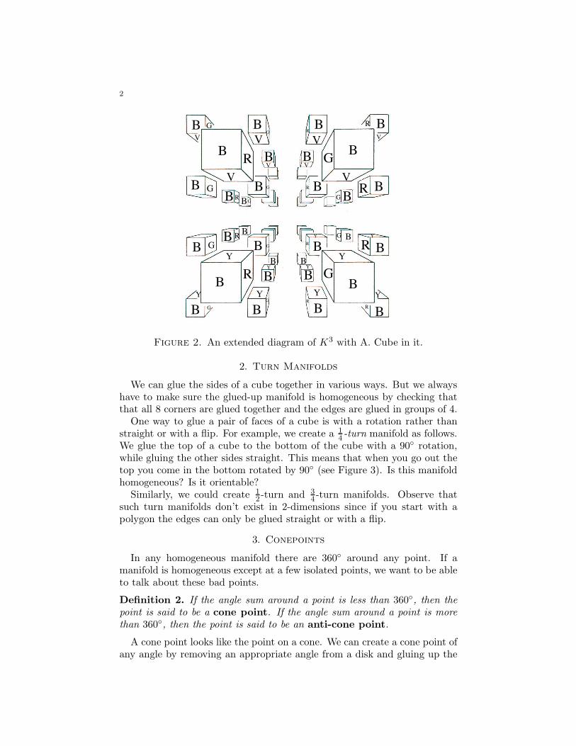
We can glue the sides of a cube together in various ways. But we alwayshave to make sure the glued-up manifold is homogeneous by checking thatthat all 8 corners are glued together and the edges are glued in groups of 4.
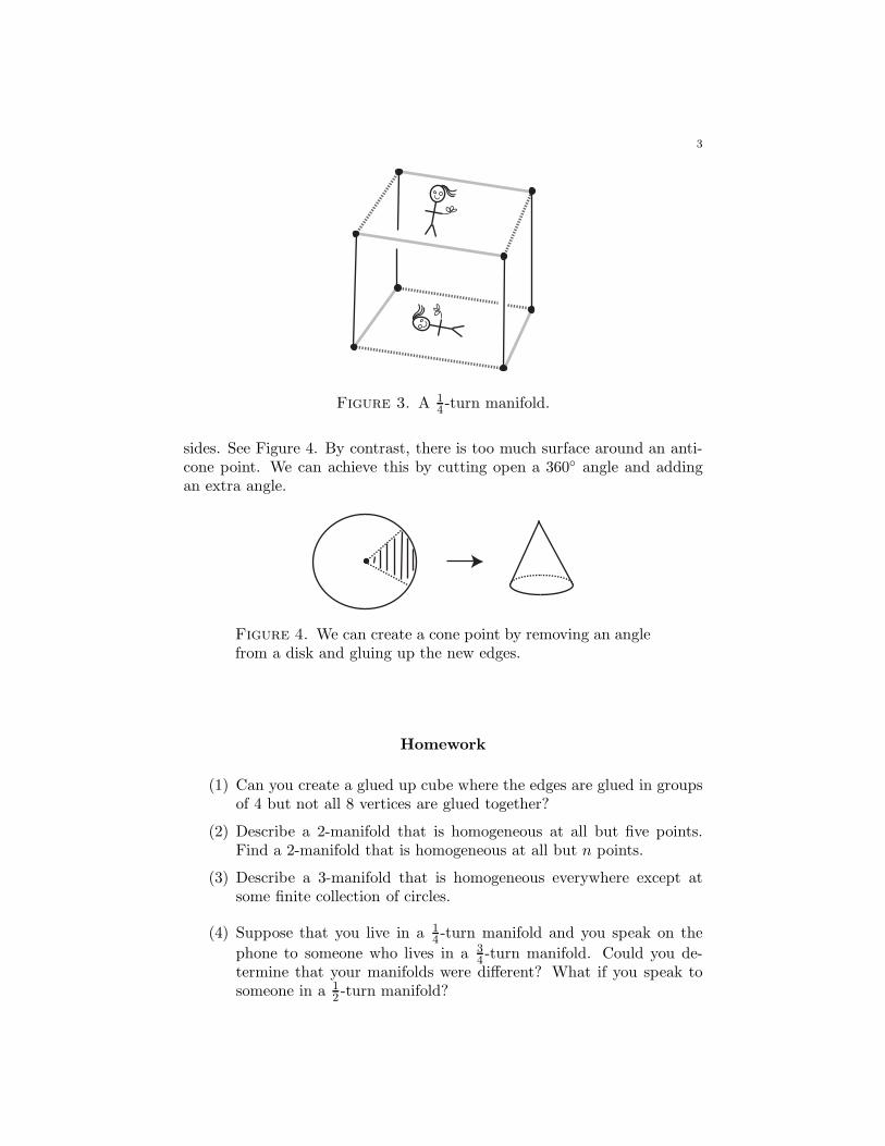
One way to glue a pair of faces of a cube is with a rotation rather thanstraight or with a flip. For example, we create a 1
4-turn manifold as follows.
We glue the top of a cube to the bottom of the cube with a 90◦ rotation,while gluing the other sides straight. This means that when you go out thetop you come in the bottom rotated by 90◦ (see Figure 3). Is this manifoldhomogeneous? Is it orientable?
Similarly, we could create 1
2-turn and 3
4-turn manifolds. Observe that
such turn manifolds don’t exist in 2-dimensions since if you start with apolygon the edges can only be glued straight or with a flip.
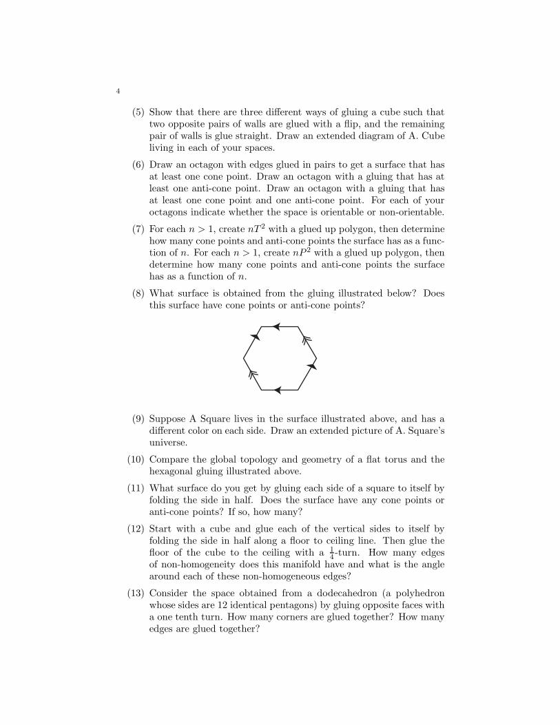
3. Conepoints
In any homogeneous manifold there are 360◦ around any point. If amanifold is homogeneous except at a few isolated points, we want to be ableto talk about these bad points.
Definition 2. If the angle sum around a point is less than 360◦, then thepoint is said to be a cone point. If the angle sum around a point is morethan 360◦, then the point is said to be an anti-cone point.
A cone point looks like the point on a cone. We can create a cone point ofany angle by removing an appropriate angle from a disk and gluing up the
3
Figure 3. A 1
4-turn manifold.
sides. See Figure 4. By contrast, there is too much surface around an anti-cone point. We can achieve this by cutting open a 360◦ angle and addingan extra angle.
Figure 4. We can create a cone point by removing an anglefrom a disk and gluing up the new edges.
Homework
(1) Can you create a glued up cube where the edges are glued in groupsof 4 but not all 8 vertices are glued together?
(2) Describe a 2-manifold that is homogeneous at all but five points.Find a 2-manifold that is homogeneous at all but n points.
(3) Describe a 3-manifold that is homogeneous everywhere except atsome finite collection of circles.
(4) Suppose that you live in a 1
4-turn manifold and you speak on the
phone to someone who lives in a 3
4-turn manifold. Could you de-
termine that your manifolds were different? What if you speak tosomeone in a 1
2-turn manifold?
4
(5) Show that there are three different ways of gluing a cube such thattwo opposite pairs of walls are glued with a flip, and the remainingpair of walls is glue straight. Draw an extended diagram of A. Cubeliving in each of your spaces.
(6) Draw an octagon with edges glued in pairs to get a surface that hasat least one cone point. Draw an octagon with a gluing that has atleast one anti-cone point. Draw an octagon with a gluing that hasat least one cone point and one anti-cone point. For each of youroctagons indicate whether the space is orientable or non-orientable.
(7) For each n > 1, create nT 2 with a glued up polygon, then determinehow many cone points and anti-cone points the surface has as a func-tion of n. For each n > 1, create nP 2 with a glued up polygon, thendetermine how many cone points and anti-cone points the surfacehas as a function of n.
(8) What surface is obtained from the gluing illustrated below? Doesthis surface have cone points or anti-cone points?
(9) Suppose A Square lives in the surface illustrated above, and has adifferent color on each side. Draw an extended picture of A. Square’suniverse.
(10) Compare the global topology and geometry of a flat torus and thehexagonal gluing illustrated above.
(11) What surface do you get by gluing each side of a square to itself byfolding the side in half. Does the surface have any cone points oranti-cone points? If so, how many?
(12) Start with a cube and glue each of the vertical sides to itself byfolding the side in half along a floor to ceiling line. Then glue thefloor of the cube to the ceiling with a 1
4-turn. How many edges
of non-homogeneity does this manifold have and what is the anglearound each of these non-homogeneous edges?
(13) Consider the space obtained from a dodecahedron (a polyhedronwhose sides are 12 identical pentagons) by gluing opposite faces witha one tenth turn. How many corners are glued together? How manyedges are glued together?
5
(14) Suppose we live in a dodecahedron with opposite pairs of faces gluedwith a 1/10 turn. Can you tell the difference between this manifoldand a dodecahedron with opposite pairs of faces glued with a 3/10turn?
(15) Suppose that A. Square lives alone in Flatland. When A. Squarelooks around, how many images of himself does he see if Flatland iseach of the following. Draw an extended picture in each case.a) An infinitely long cylinder?b) An infinite cone with cone angle 90◦? c) An infinite cone withcone angle 73◦? d) An infinite cone with cone angle 300◦?
B
O O O O
B
O O
B
O O
BB B B
B
OO
B B B B
OO O
BB
R
R
G
G
G
G
G
G
RR
R
R
O
B B
O
Y Y
R
G
G
Y YY Y
R
G
R
B
Y Y
V V
V V VV
V V
G
R
Y Y
R
R
G
G
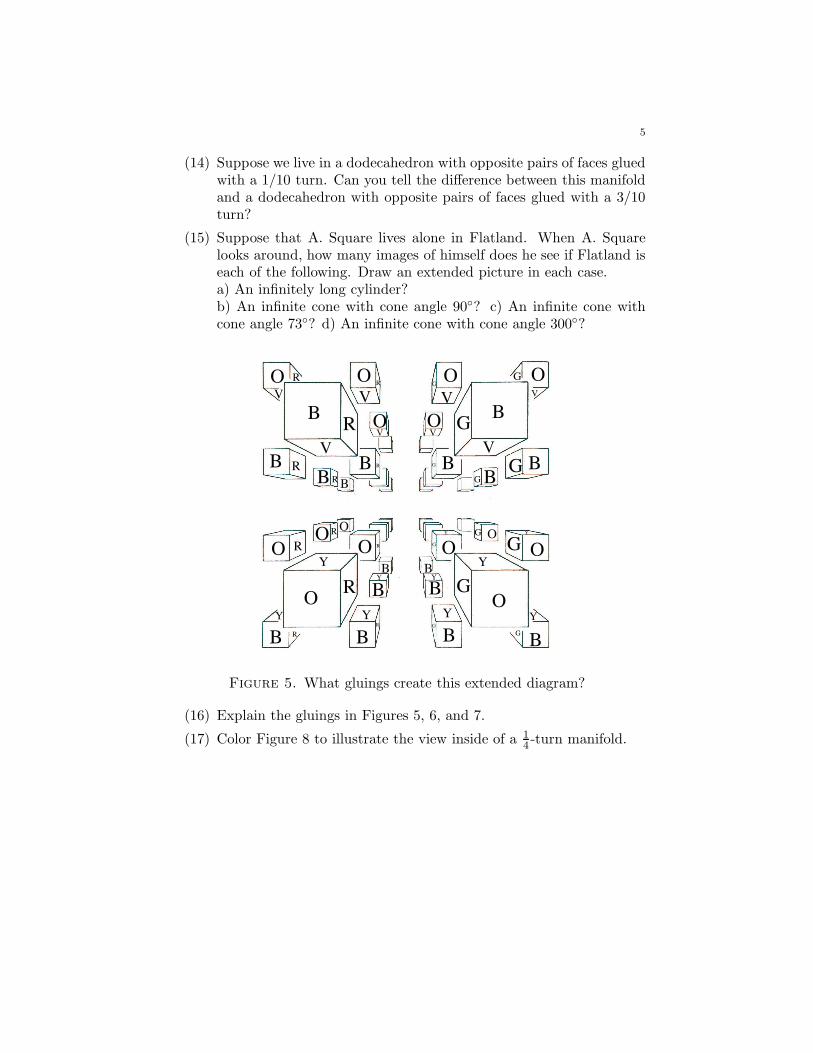
Figure 5. What gluings create this extended diagram?
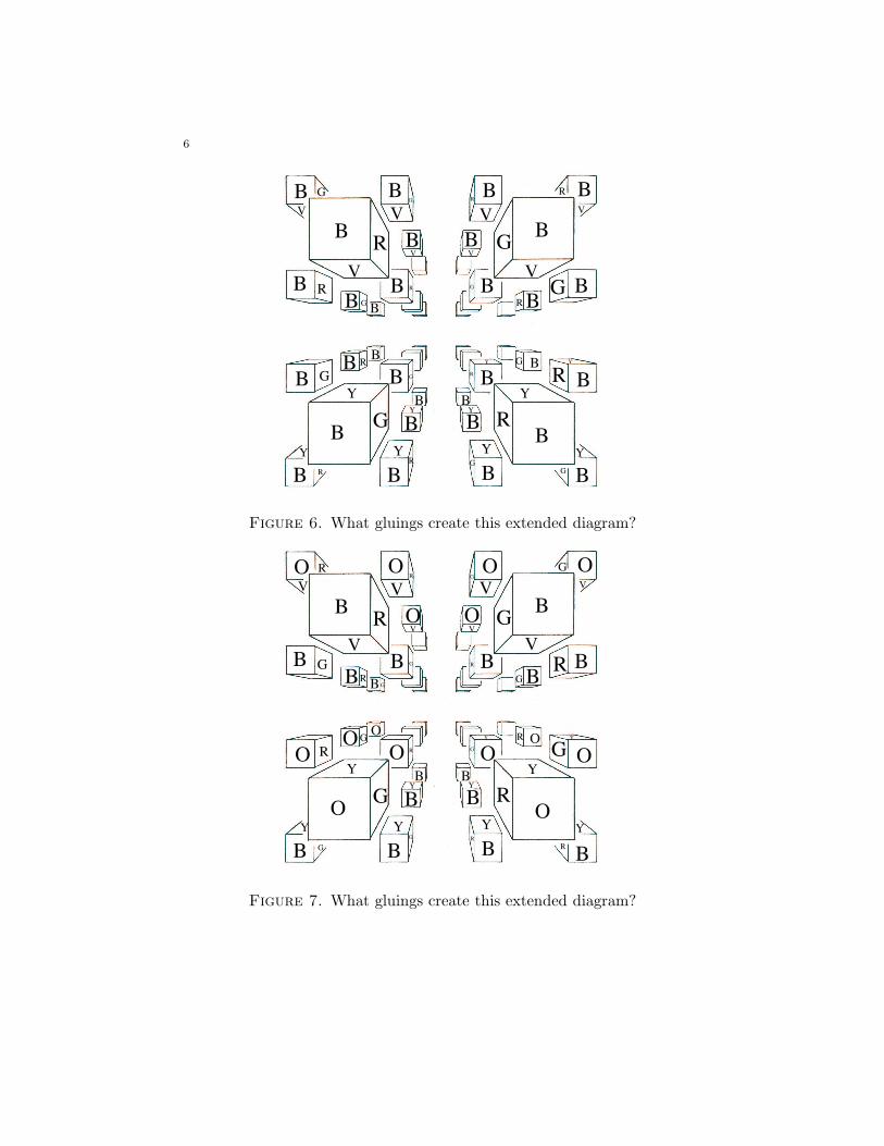
(16) Explain the gluings in Figures 5, 6, and 7.
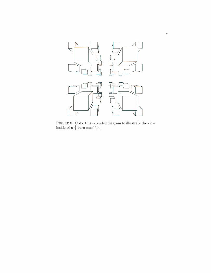
(17) Color Figure 8 to illustrate the view inside of a 1
4-turn manifold.
6
B
B B B B
B
B B
B
B B
BB B B
B
BB
B B B B
BB B
BB
R
G
G
R
G
R
R
G
G
G
R
G
B
B B
B
Y Y
R
R
Y YY Y
G
G
G
B
Y Y
V V
V V VV
V V
R
R
Y Y
R
R
G
G
R
Figure 6. What gluings create this extended diagram?
B
O O O O
B
O O
B
O O
BB B B
B
OO
B B B B
OO O
BB
R
G
R
G
G
R
G
R
R
R
G
R
O
B B
O
Y Y
R
G
G
Y YY Y
G
R
R
B
Y Y
V V
V V V V
V V
G
G
Y Y
G
G
R
R
G
Figure 7. What gluings create this extended diagram?
7
Figure 8. Color this extended diagram to illustrate the viewinside of a 1
4-turn manifold.
Lecture 7
1. Homogeneous Geometries
There are three types of local geometries for surfaces which are homoge-neous. In each there are 360◦ around every point. However, the sum of theangles of triangles is different in each of the three geometries. Here are thetypes of geometries:
1) Flat or Euclidean geometry. In flat surfaces the sum of the angles ofany triangle is 180◦. These surfaces are said to have zero curvature.
2) Elliptical or spherical geometry. In elliptical surfaces the sum of theangles of any triangle is greater than 180◦. These surfaces are said to havepositive curvature.
3) Hyperbolic geometry. In hyperbolic surfaces the sum of the angles ofany triangle is less than 180◦. These surfaces are said to have negative
curvature.
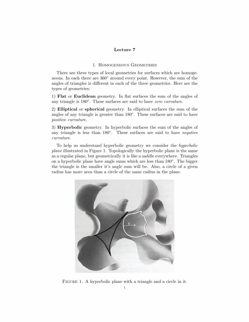
To help us understand hyperbolic geometry we consider the hyperbolic
plane illustrated in Figure 1. Topologically the hyperbolic plane is the sameas a regular plane, but geometrically it is like a saddle everywhere. Triangleson a hyperbolic plane have angle sums which are less than 180◦. The biggerthe triangle is the smaller it’s angle sum will be. Also, a circle of a givenradius has more area than a circle of the same radius in the plane.
R
Figure 1. A hyperbolic plane with a triangle and a circle in it.
1
2
We would like all finite area 2-manifolds to have one of the homogeneousgeometries. We know that every such surface is either a sphere, a connectedsum of tori, or a connected sum of projective planes. We have seen that T 2
and K2 = 2P 2 have flat geometry, and S2 and P 2 have spherical geometry.We want to create homogeneous versions of nT 2 and nP 2 for other valuesof n. The key idea is that a glued up polygon does not have to be drawnon a flat piece of paper. It could be drawn on the surface of a sphere or ona hyperbolic plane. For example, we saw that if P 2 is drawn as a glued-updisk in the plane then it won’t be homogeneous on it’s boundary, but if itis drawn on a hemisphere than it will have spherical geometry.
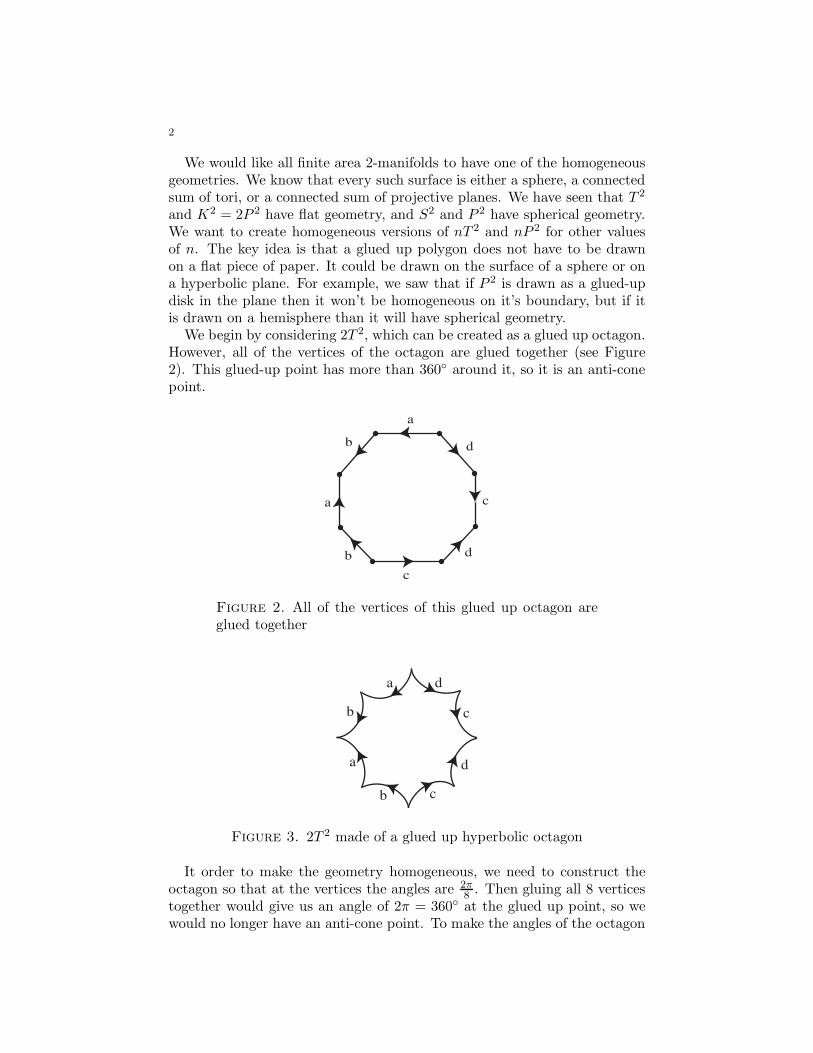
We begin by considering 2T 2, which can be created as a glued up octagon.However, all of the vertices of the octagon are glued together (see Figure2). This glued-up point has more than 360◦ around it, so it is an anti-conepoint.
a
d
c
d
c
b
a
b
Figure 2. All of the vertices of this glued up octagon areglued together
a d
c
d
cb
a
b
Figure 3. 2T 2 made of a glued up hyperbolic octagon
It order to make the geometry homogeneous, we need to construct theoctagon so that at the vertices the angles are 2π
8. Then gluing all 8 vertices
together would give us an angle of 2π = 360◦ at the glued up point, so wewould no longer have an anti-cone point. To make the angles of the octagon
3
smaller than they are on a flat plane, we draw the octagon on a hyperbolicplane. Since the sides of the octagon are made of hyperbolic geodesics, theangles between the sides are smaller than they were on the plane (see Figure3). Furthermore, the bigger we draw the octagon on a hyperbolic plane, thesmaller the angles will be. So we can choose to draw it exactly the right sizeso that each of the angles is precisely 2π
8. This glued-up octagon is now 2T 2
with homogeneous hyperbolic geometry.For any n ≥ 2, an nT 2 is made of a glued up 4n-gon with all of its vertices
glued together. We can create a homogeneous nT 2 with hyperbolic geometryby gluing up a hyperbolic 4n-gon which has corner angles of exactly 2π
4n. In
this way the glued-up corner point will have an angle of 2π in the nT 2. Thisglued-up 4n-gon will have homogeneous hyperbolic geometry.
For homework you will construct an nP 2 with homogeneous geometryfor all n > 2. Thus we have a complete list of all finite area 2-manifolds,and each one has a homogeneous geometry. This means 2-manifolds arewonderful.
2. The 3-sphere
An important 3-manifold which we have not yet studied is the 3-dimensionalsphere, S3. We several ways to think about S3 which are analogous toways that we can think about S2. The first approach is to consider S2 ={(x, y, z)|x2 + y2 + z2 = 1} as the unit sphere in R
3. By analogy, S3 ={(x, y, z, w)|x2 + y2 + z2 + w2 = 1} is the unit sphere in R
4. This is a goodanalytical approach, but it doesn’t give us much intuition about how tovisualize S3.
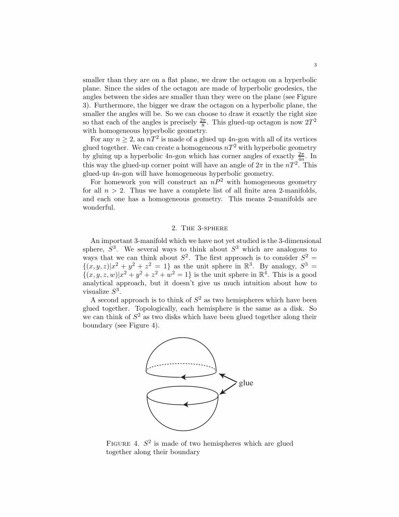
A second approach is to think of S2 as two hemispheres which have beenglued together. Topologically, each hemisphere is the same as a disk. Sowe can think of S2 as two disks which have been glued together along theirboundary (see Figure 4).
glue
Figure 4. S2 is made of two hemispheres which are gluedtogether along their boundary
4
glue
Ball 1 Ball 2
S3
Figure 5. S3 is made of two balls which are glued togetheralong their boundary
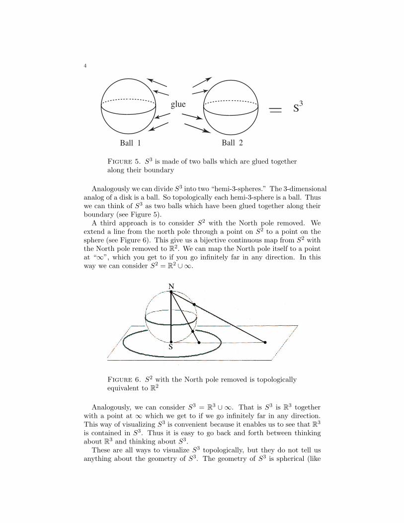
Analogously we can divide S3 into two “hemi-3-spheres.” The 3-dimensionalanalog of a disk is a ball. So topologically each hemi-3-sphere is a ball. Thuswe can think of S3 as two balls which have been glued together along theirboundary (see Figure 5).
A third approach is to consider S2 with the North pole removed. Weextend a line from the north pole through a point on S2 to a point on thesphere (see Figure 6). This give us a bijective continuous map from S2 withthe North pole removed to R
2. We can map the North pole itself to a pointat “∞”, which you get to if you go infinitely far in any direction. In thisway we can consider S2 = R
2 ∪∞.
N
S
Figure 6. S2 with the North pole removed is topologicallyequivalent to R
2
Analogously, we can consider S3 = R3 ∪ ∞. That is S3 is R
3 togetherwith a point at ∞ which we get to if we go infinitely far in any direction.This way of visualizing S3 is convenient because it enables us to see that R
3
is contained in S3. Thus it is easy to go back and forth between thinkingabout R
3 and thinking about S3.These are all ways to visualize S3 topologically, but they do not tell us
anything about the geometry of S3. The geometry of S3 is spherical (like
5
S2), so the sum of the angles of any triangle in S3 is greater than 180◦. Infact, S3 is a possibility for our own universe.
Homework
(1) Explain how to create an nP 2 with hyperbolic geometry for anyn > 2. Explain why this method won’t work for n = 1 or n = 2.
(2) Suppose that we glue opposite faces of a cube in each of the followingways. Is it possible to get a homogenous manifold? Explain.a) One pair of sides is glued with a flip, and the other two pairs areeach glued with a 180◦ rotation.b) One pair of sides is glued with a flip, and the other two pairs areeach glued with a 90◦ rotation.c) Each pair is glued with a flip.
(3) Imagine a large square with a smaller square cut out of it. Gluetogether opposite sides of each square. What shape do you get?
(4) Suppose A. Square lives alone in the following space. He has adifferent color on each of his sides. He can see in all directions andhas depth perception. Draw an extended picture of his space. Is hisspace homogeneous?
(5) Use the parallel postulate of Euclidean geometry (i.e. if a line crossestwo parallel lines then the interior angles are equal) to prove thatthe sum of the angles of any flat triangle is π radians.
(6) Prove that the sum of the angles of a flat n-gon is (n−2)π radians.
(7) Consider a unit sphere. What is the area of the double wedge createdby two great circles where the wedge angles are π
3? Justify your
conclusion.
(8) Let L(x) be the area of the double wedge on a unit sphere createdby two great circles whose wedge angle is equal to x radians. Finda formula for L(x) in terms of x. Justify your conclusion.
6
(9) Let T be a triangle on the unit sphere with angles a, b, and c. Writea formula for the area of T in terms of L(a), L(b), and L(c). Use itto show that the area of T is a + b + c − π. Note this implies thatbigger triangles on the sphere have larger angle sums.
(10) Given that the area of a triangle T on a unit sphere is a + b + c− π,find a formula for the area of a similar triangle on a sphere of radiusr. Justify your formula.
(11) Prove that the area of an n-gon on a unit sphere is θ1 + · · · + θn −(n − 2)π, where the angles of the n-gon are θ1, . . . , θn .
(12) Divide a unit sphere into polygonal regions letting f denote the totalnumber of regions, letting e denote the total number of edges, andletting v denote the total number of vertices. Use the result of theabove problem to prove that no matter how the unit sphere is dividedup into polygons, we always get the equation v − e + f = 2.
Lecture 8
Lectures 8 - 10 are based on The Knot Book, by Colin Adams
1. Knots, links, and projections
Knot theory is a subfield of topology whose broad goal is to developmethods to determine for any given pair of knots whether or not one canbe deformed to the other. A simpler, yet still unsolved problem, is to findan algorithm that will to determine for any knot whether or not it can bedeformed into a plane. We begin with some definitions.
Definition 1. A knot is an embedding (i.e., a positioning) of a circle inR
3. A link is an embedding of one or more disjoint circles in R3. Each
circle in a link is called a component of the link.
Notice that according to this definition, a knot is a link with a singlecomponent. So when we use the word “link” we could mean either a knotor a link with multiple components.
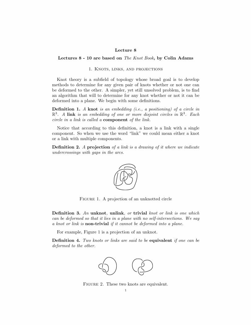
Definition 2. A projection of a link is a drawing of it where we indicateundercrossings with gaps in the arcs.
Figure 1. A projection of an unknotted circle
Definition 3. An unknot, unlink, or trivial knot or link is one whichcan be deformed so that it lies in a plane with no self-intersections. We saya knot or link is non-trivial if it cannot be deformed into a plane.
For example, Figure 1 is a projection of an unknot.
Definition 4. Two knots or links are said to be equivalent if one can bedeformed to the other.
Figure 2. These two knots are equivalent.
1
2
We often are sloppy with notation and say that two knots are the samewhen we actually mean they are equivalent.
Just as we used the connected sum operation to build complicated mani-folds from simpler ones, we can define the connected sum of knots in orderto build complicated knots from simpler ones.
Definition 5. Let P be a plane in R3, and let A be an arc in P . Suppose
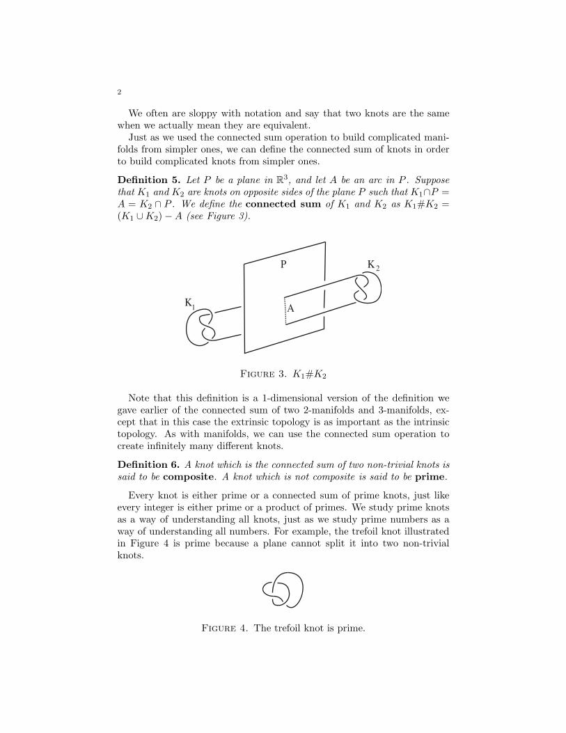
that K1 and K2 are knots on opposite sides of the plane P such that K1∩P =A = K2 ∩ P . We define the connected sum of K1 and K2 as K1#K2 =(K1 ∪ K2) − A (see Figure 3).
A
P
K1
K2
Figure 3. K1#K2
Note that this definition is a 1-dimensional version of the definition wegave earlier of the connected sum of two 2-manifolds and 3-manifolds, ex-cept that in this case the extrinsic topology is as important as the intrinsictopology. As with manifolds, we can use the connected sum operation tocreate infinitely many different knots.
Definition 6. A knot which is the connected sum of two non-trivial knots issaid to be composite. A knot which is not composite is said to be prime.
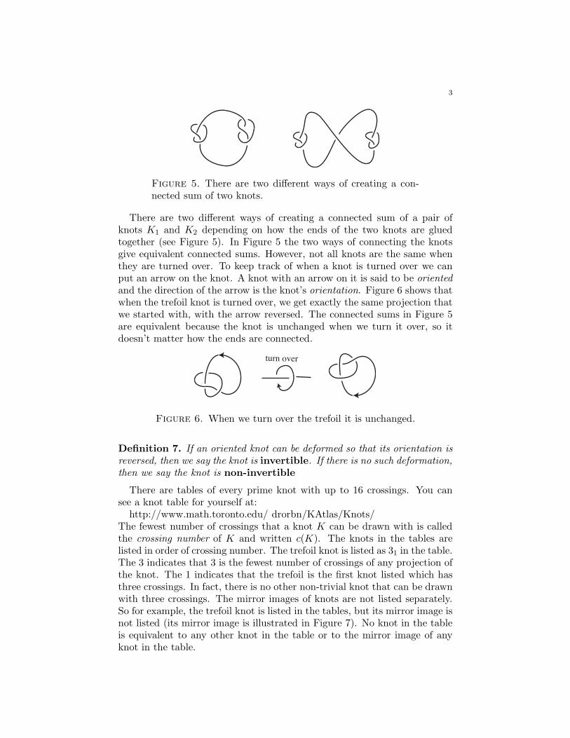
Every knot is either prime or a connected sum of prime knots, just likeevery integer is either prime or a product of primes. We study prime knotsas a way of understanding all knots, just as we study prime numbers as away of understanding all numbers. For example, the trefoil knot illustratedin Figure 4 is prime because a plane cannot split it into two non-trivialknots.
Figure 4. The trefoil knot is prime.
3
Figure 5. There are two different ways of creating a con-nected sum of two knots.
There are two different ways of creating a connected sum of a pair ofknots K1 and K2 depending on how the ends of the two knots are gluedtogether (see Figure 5). In Figure 5 the two ways of connecting the knotsgive equivalent connected sums. However, not all knots are the same whenthey are turned over. To keep track of when a knot is turned over we canput an arrow on the knot. A knot with an arrow on it is said to be orientedand the direction of the arrow is the knot’s orientation. Figure 6 shows thatwhen the trefoil knot is turned over, we get exactly the same projection thatwe started with, with the arrow reversed. The connected sums in Figure 5are equivalent because the knot is unchanged when we turn it over, so itdoesn’t matter how the ends are connected.
turn over
Figure 6. When we turn over the trefoil it is unchanged.
Definition 7. If an oriented knot can be deformed so that its orientation isreversed, then we say the knot is invertible. If there is no such deformation,then we say the knot is non-invertible
There are tables of every prime knot with up to 16 crossings. You cansee a knot table for yourself at:
http://www.math.toronto.edu/ drorbn/KAtlas/Knots/The fewest number of crossings that a knot K can be drawn with is calledthe crossing number of K and written c(K). The knots in the tables arelisted in order of crossing number. The trefoil knot is listed as 31 in the table.The 3 indicates that 3 is the fewest number of crossings of any projection ofthe knot. The 1 indicates that the trefoil is the first knot listed which hasthree crossings. In fact, there is no other non-trivial knot that can be drawnwith three crossings. The mirror images of knots are not listed separately.So for example, the trefoil knot is listed in the tables, but its mirror image isnot listed (its mirror image is illustrated in Figure 7). No knot in the tableis equivalent to any other knot in the table or to the mirror image of anyknot in the table.
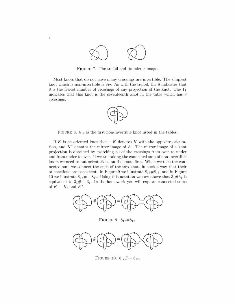
4
Figure 7. The trefoil and its mirror image.
Most knots that do not have many crossings are invertible. The simplestknot which is non-invertible is 817. As with the trefoil, the 8 indicates that8 is the fewest number of crossings of any projection of the knot. The 17indicates that this knot is the seventeenth knot in the table which has 8crossings.
Figure 8. 817 is the first non-invertible knot listed in the tables.
If K is an oriented knot then −K denotes K with the opposite orienta-tion, and K∗ denotes the mirror image of K. The mirror image of a knotprojection is obtained by switching all of the crossings from over to underand from under to over. If we are taking the connected sum of non-invertibleknots we need to put orientations on the knots first. When we take the con-nected sum we connect the ends of the two knots in such a way that theirorientations are consistent. In Figure 9 we illustrate 817#817, and in Figure10 we illustrate 817#− 817. Using this notation we saw above that 31#31 isequivalent to 31# − 31. In the homework you will explore connected sumsof K, −K, and K∗.
# =
Figure 9. 817#817.
# =
Figure 10. 817# − 817.
5
2. Link Invariants
To show that two links are equivalent we only have to produce a deforma-tion from one to the other. But to prove that two links are not equivalent,we would have to show that there can be no such deformation. This mightseem impossible. However, it can be easy with the help of “link invariants”.
Definition 8. A knot or link invariant is a function f from the set of allknots or links to a set of mathematical objects (e.g., numbers, polynomials,groups, etc.) such that if L and L′ are equivalent then f(L) = f(L′).
For example, let’s consider f : {links} → N where f(L) is the number ofcomponents (i.e., the number of circles) of L. If L is equivalent to L′, thenf(L) = f(L′). Hence f is a link invariant. Suppose we want to comparethe Hopf link (illustrated in Figure 11) to the trefoil knot. We know thatf(31) = 1 and f(Hopf) = 2. Hence the trefoil is not equivalent to the Hopflink. On the other hand, f(41) = 1 = f(31), where 41 denotes the figureeight knot. But this does not imply that the figure eight knot is equivalentto the trefoil. So this invariant, does not allow as to distinguish differentknots
Figure 11. The Hopf link.
The idea of an invariant is that to each link we assign a mathematical valuewhich is simpler than the link itself. If two links are assigned different valuesthen we know that the links are not equivalent. If two links are assigned thesame value, it doesn’t tell us anything (as we saw in the example above).No known link invariant distinguishes every pair of inequivalent links. Sowe may have to try several invariants before we are able to distinguish twolinks or two knots. We will introduce more invariants after some definitions.Remember that an oriented link, is a link with an arrow on each component.
Negative Positive
Figure 12. A negative (left-handed) crossing and a positive(right-handed) crossing.
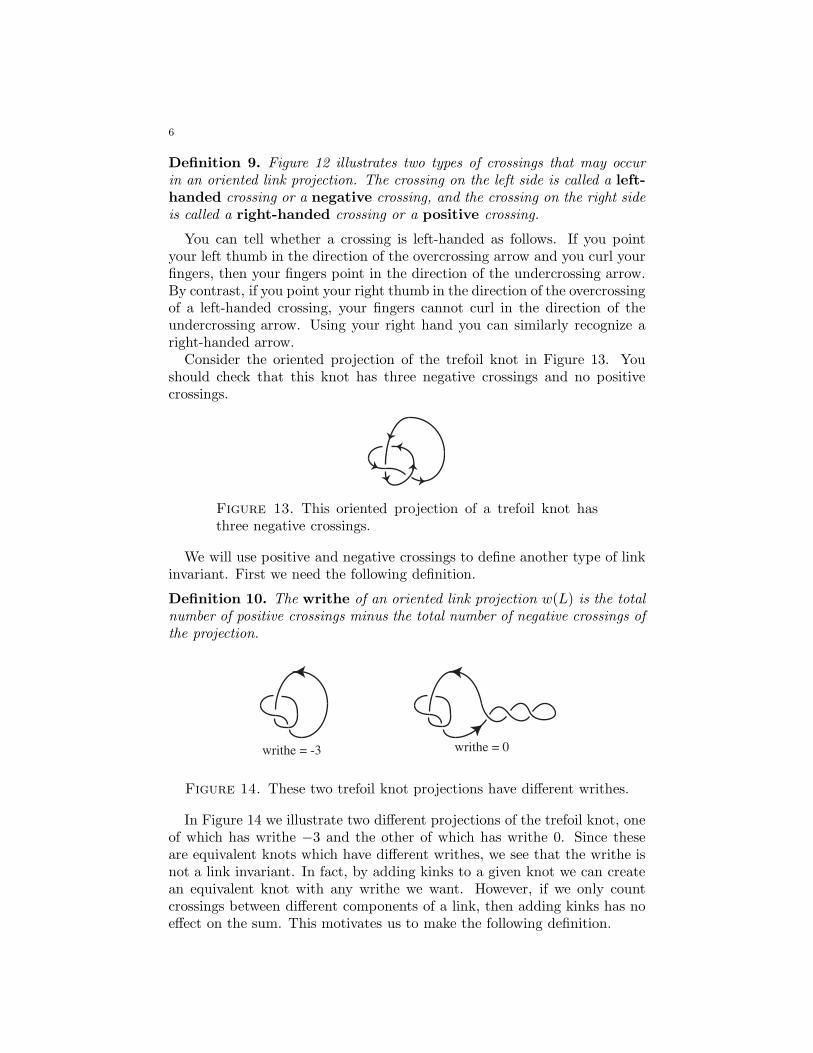
6
Definition 9. Figure 12 illustrates two types of crossings that may occurin an oriented link projection. The crossing on the left side is called a left-
handed crossing or a negative crossing, and the crossing on the right sideis called a right-handed crossing or a positive crossing.
You can tell whether a crossing is left-handed as follows. If you pointyour left thumb in the direction of the overcrossing arrow and you curl yourfingers, then your fingers point in the direction of the undercrossing arrow.By contrast, if you point your right thumb in the direction of the overcrossingof a left-handed crossing, your fingers cannot curl in the direction of theundercrossing arrow. Using your right hand you can similarly recognize aright-handed arrow.
Consider the oriented projection of the trefoil knot in Figure 13. Youshould check that this knot has three negative crossings and no positivecrossings.
Figure 13. This oriented projection of a trefoil knot hasthree negative crossings.
We will use positive and negative crossings to define another type of linkinvariant. First we need the following definition.
Definition 10. The writhe of an oriented link projection w(L) is the totalnumber of positive crossings minus the total number of negative crossings ofthe projection.
writhe = -3 writhe = 0
Figure 14. These two trefoil knot projections have different writhes.
In Figure 14 we illustrate two different projections of the trefoil knot, oneof which has writhe −3 and the other of which has writhe 0. Since theseare equivalent knots which have different writhes, we see that the writhe isnot a link invariant. In fact, by adding kinks to a given knot we can createan equivalent knot with any writhe we want. However, if we only countcrossings between different components of a link, then adding kinks has noeffect on the sum. This motivates us to make the following definition.
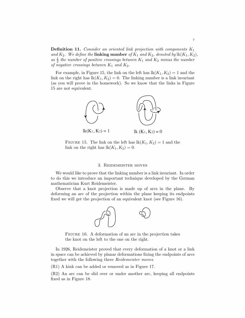
7
Definition 11. Consider an oriented link projection with components K1
and K2. We define the linking number of K1 and K2, denoted by lk(K1,K2),as 1
2the number of positive crossings between K1 and K2 minus the number
of negative crossings between K1 and K2.
For example, in Figure 15, the link on the left has lk(K1,K2) = 1 and thelink on the right has lk(K1,K2) = 0. The linking number is a link invariant(as you will prove in the homework). So we know that the links in Figure15 are not equivalent.
lk(K1, K2) = 1 lk (K1, K2) = 0
Figure 15. The link on the left has lk(K1,K2) = 1 and thelink on the right has lk(K1,K2) = 0.
3. Reidemeister moves
We would like to prove that the linking number is a link invariant. In orderto do this we introduce an important technique developed by the Germanmathematician Kurt Reidemeister.
Observe that a knot projection is made up of arcs in the plane. Bydeforming an arc of the projection within the plane keeping its endpointsfixed we will get the projection of an equivalent knot (see Figure 16).
Figure 16. A deformation of an arc in the projection takesthe knot on the left to the one on the right.
In 1926, Reidemeister proved that every deformation of a knot or a linkin space can be achieved by planar deformations fixing the endpoints of arcstogether with the following three Reidemeister moves.
(R1) A kink can be added or removed as in Figure 17.
(R2) An arc can be slid over or under another arc, keeping all endpointsfixed as in Figure 18.
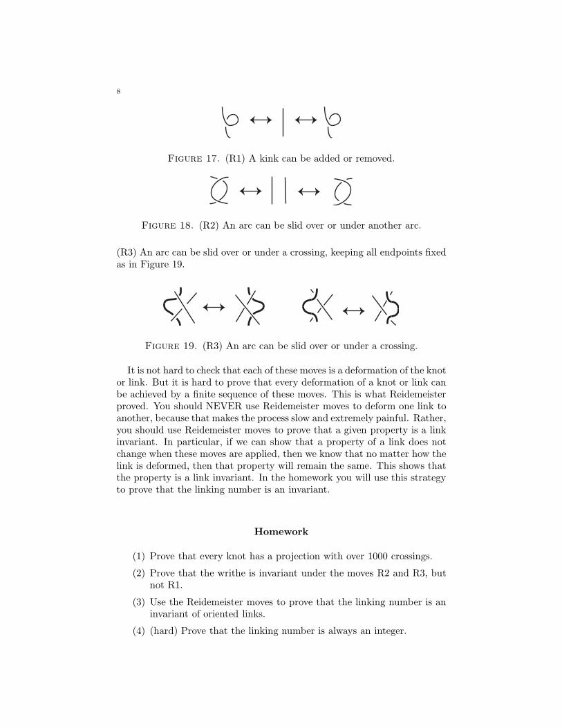
8
Figure 17. (R1) A kink can be added or removed.
Figure 18. (R2) An arc can be slid over or under another arc.
(R3) An arc can be slid over or under a crossing, keeping all endpoints fixedas in Figure 19.
Figure 19. (R3) An arc can be slid over or under a crossing.
It is not hard to check that each of these moves is a deformation of the knotor link. But it is hard to prove that every deformation of a knot or link canbe achieved by a finite sequence of these moves. This is what Reidemeisterproved. You should NEVER use Reidemeister moves to deform one link toanother, because that makes the process slow and extremely painful. Rather,you should use Reidemeister moves to prove that a given property is a linkinvariant. In particular, if we can show that a property of a link does notchange when these moves are applied, then we know that no matter how thelink is deformed, then that property will remain the same. This shows thatthe property is a link invariant. In the homework you will use this strategyto prove that the linking number is an invariant.
Homework
(1) Prove that every knot has a projection with over 1000 crossings.
(2) Prove that the writhe is invariant under the moves R2 and R3, butnot R1.
(3) Use the Reidemeister moves to prove that the linking number is aninvariant of oriented links.
(4) (hard) Prove that the linking number is always an integer.
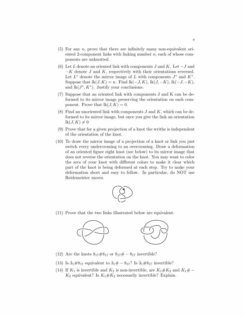
9
(5) For any n, prove that there are infinitely many non-equivalent ori-ented 2-component links with linking number n, each of whose com-ponents are unknotted.
(6) Let L denote an oriented link with components J and K. Let −J and−K denote J and K, respectively with their orientations reversed.Let L∗ denote the mirror image of L with components J∗ and K∗.Suppose that lk(J,K) = n. Find lk(−J,K), lk(J,−K), lk(−J,−K),and lk(J∗,K∗). Justify your conclusions.
(7) Suppose that an oriented link with components J and K can be de-formed to its mirror image preserving the orientation on each com-ponent. Prove that lk(J,K) = 0.
(8) Find an unoriented link with components J and K, which can be de-formed to its mirror image, but once you give the link an orientationlk(J,K) 6= 0
(9) Prove that for a given projection of a knot the writhe is independentof the orientation of the knot.
(10) To draw the mirror image of a projection of a knot or link you justswitch every undercrossing to an overcrossing. Draw a deformationof an oriented figure eight knot (see below) to its mirror image thatdoes not reverse the orientation on the knot. You may want to colorthe arcs of your knot with different colors to make it clear whichpart of the knot is being deformed at each step. Try to make yourdeformation short and easy to follow. In particular, do NOT useReidemeister moves.
(11) Prove that the two links illustrated below are equivalent.
(12) Are the knots 817#817 or 817# − 817 invertible?
(13) Is 31#817 equivalent to 31# − 817? Is 31#817 invertible?
(14) If K1 is invertible and K2 is non-invertible, are K1#K2 and K1#−K2 equivalent? Is K1#K2 necessarily invertible? Explain.
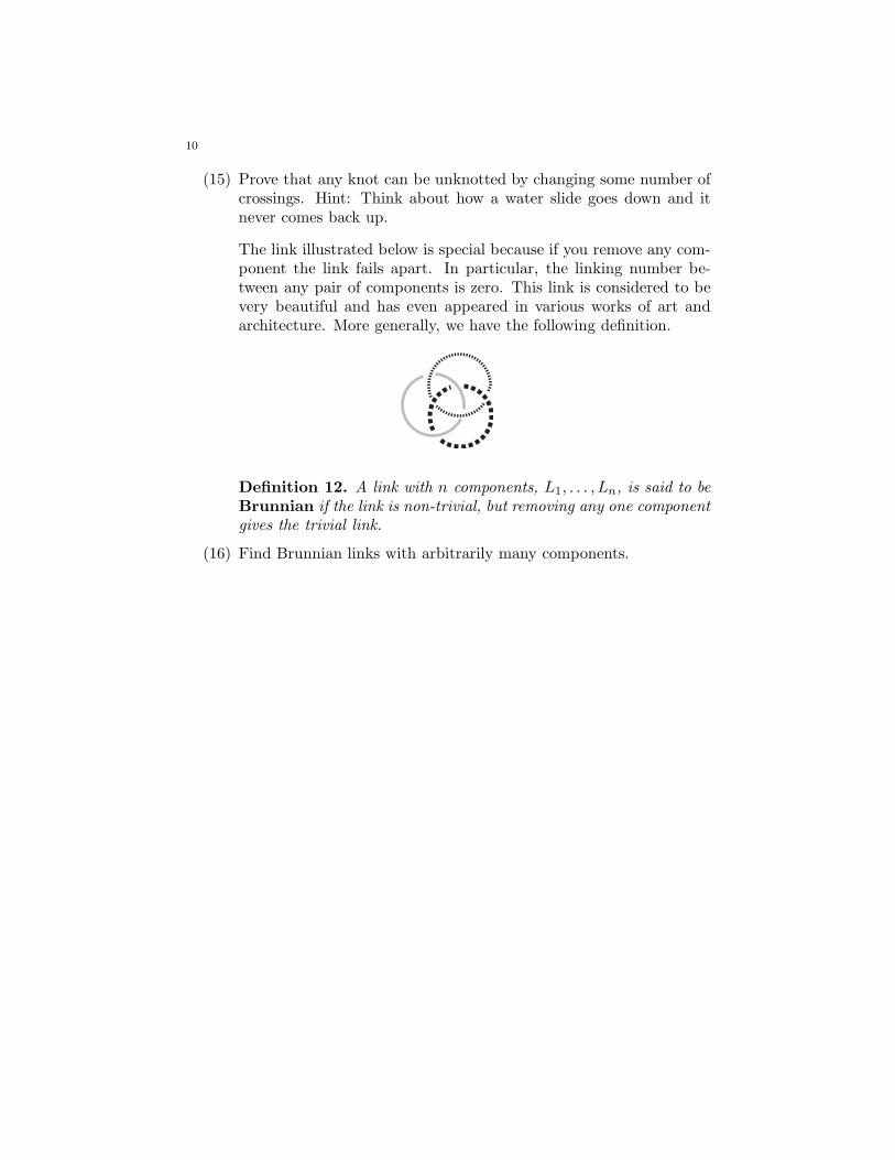
10
(15) Prove that any knot can be unknotted by changing some number ofcrossings. Hint: Think about how a water slide goes down and itnever comes back up.
The link illustrated below is special because if you remove any com-ponent the link fails apart. In particular, the linking number be-tween any pair of components is zero. This link is considered to bevery beautiful and has even appeared in various works of art andarchitecture. More generally, we have the following definition.
Definition 12. A link with n components, L1, . . . , Ln, is said to beBrunnian if the link is non-trivial, but removing any one componentgives the trivial link.
(16) Find Brunnian links with arbitrarily many components.
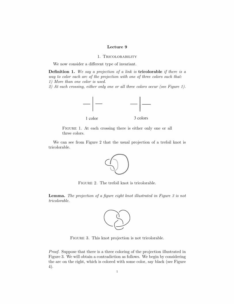
Lecture 9
1. Tricolorability
We now consider a different type of invariant.
Definition 1. We say a projection of a link is tricolorable if there is away to color each arc of the projection with one of three colors such that:1) More than one color is used.2) At each crossing, either only one or all three colors occur (see Figure 1).
1 color 3 colors
Figure 1. At each crossing there is either only one or allthree colors.
We can see from Figure 2 that the usual projection of a trefoil knot istricolorable.
Figure 2. The trefoil knot is tricolorable.
Lemma. The projection of a figure eight knot illustrated in Figure 3 is nottricolorable.
Figure 3. This knot projection is not tricolorable.
Proof. Suppose that there is a three coloring of the projection illustrated inFigure 3. We will obtain a contradiction as follows. We begin by consideringthe arc on the right, which is colored with some color, say black (see Figure4).
1
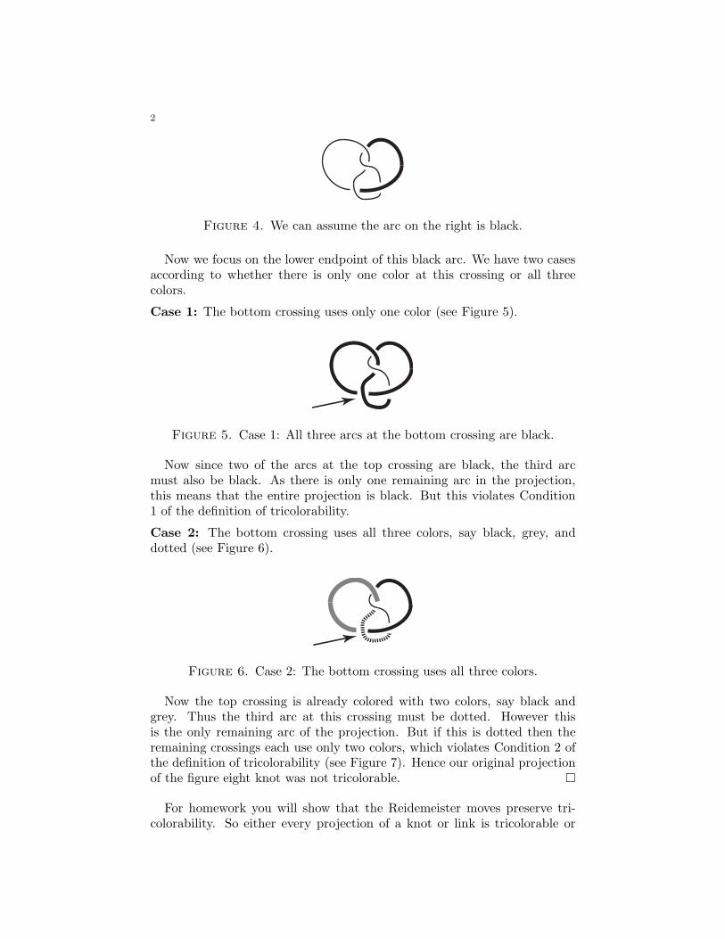
2
Figure 4. We can assume the arc on the right is black.
Now we focus on the lower endpoint of this black arc. We have two casesaccording to whether there is only one color at this crossing or all threecolors.
Case 1: The bottom crossing uses only one color (see Figure 5).
Figure 5. Case 1: All three arcs at the bottom crossing are black.
Now since two of the arcs at the top crossing are black, the third arcmust also be black. As there is only one remaining arc in the projection,this means that the entire projection is black. But this violates Condition1 of the definition of tricolorability.
Case 2: The bottom crossing uses all three colors, say black, grey, anddotted (see Figure 6).
Figure 6. Case 2: The bottom crossing uses all three colors.
Now the top crossing is already colored with two colors, say black andgrey. Thus the third arc at this crossing must be dotted. However thisis the only remaining arc of the projection. But if this is dotted then theremaining crossings each use only two colors, which violates Condition 2 ofthe definition of tricolorability (see Figure 7). Hence our original projectionof the figure eight knot was not tricolorable. �
For homework you will show that the Reidemeister moves preserve tri-colorability. So either every projection of a knot or link is tricolorable or
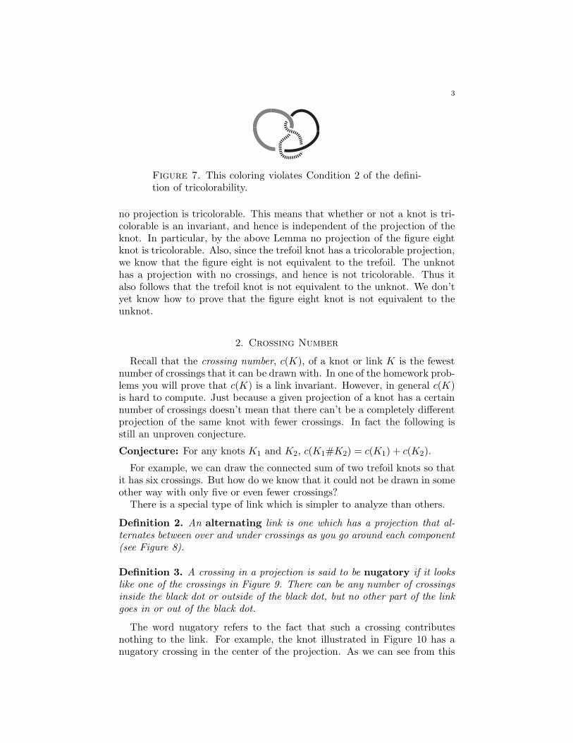
3
Figure 7. This coloring violates Condition 2 of the defini-tion of tricolorability.
no projection is tricolorable. This means that whether or not a knot is tri-colorable is an invariant, and hence is independent of the projection of theknot. In particular, by the above Lemma no projection of the figure eightknot is tricolorable. Also, since the trefoil knot has a tricolorable projection,we know that the figure eight is not equivalent to the trefoil. The unknothas a projection with no crossings, and hence is not tricolorable. Thus italso follows that the trefoil knot is not equivalent to the unknot. We don’tyet know how to prove that the figure eight knot is not equivalent to theunknot.
2. Crossing Number
Recall that the crossing number, c(K), of a knot or link K is the fewestnumber of crossings that it can be drawn with. In one of the homework prob-lems you will prove that c(K) is a link invariant. However, in general c(K)is hard to compute. Just because a given projection of a knot has a certainnumber of crossings doesn’t mean that there can’t be a completely differentprojection of the same knot with fewer crossings. In fact the following isstill an unproven conjecture.
Conjecture: For any knots K1 and K2, c(K1#K2) = c(K1) + c(K2).
For example, we can draw the connected sum of two trefoil knots so thatit has six crossings. But how do we know that it could not be drawn in someother way with only five or even fewer crossings?
There is a special type of link which is simpler to analyze than others.
Definition 2. An alternating link is one which has a projection that al-ternates between over and under crossings as you go around each component(see Figure 8).
Definition 3. A crossing in a projection is said to be nugatory if it lookslike one of the crossings in Figure 9. There can be any number of crossingsinside the black dot or outside of the black dot, but no other part of the linkgoes in or out of the black dot.
The word nugatory refers to the fact that such a crossing contributesnothing to the link. For example, the knot illustrated in Figure 10 has anugatory crossing in the center of the projection. As we can see from this
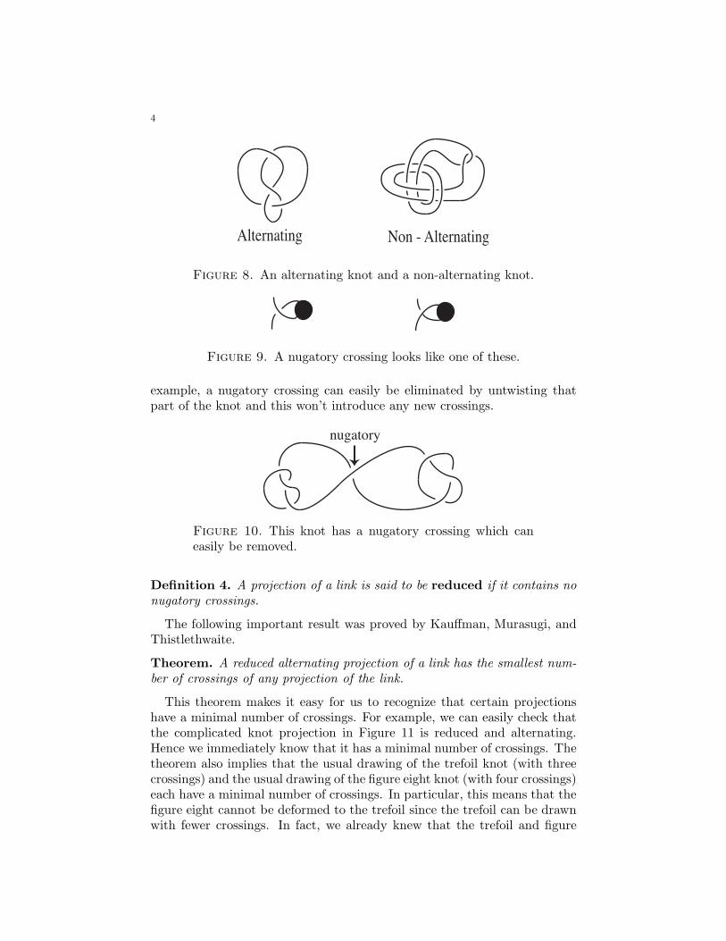
4
Alternating Non - Alternating
Figure 8. An alternating knot and a non-alternating knot.
Figure 9. A nugatory crossing looks like one of these.
example, a nugatory crossing can easily be eliminated by untwisting thatpart of the knot and this won’t introduce any new crossings.
nugatory
Figure 10. This knot has a nugatory crossing which caneasily be removed.
Definition 4. A projection of a link is said to be reduced if it contains nonugatory crossings.
The following important result was proved by Kauffman, Murasugi, andThistlethwaite.
Theorem. A reduced alternating projection of a link has the smallest num-ber of crossings of any projection of the link.
This theorem makes it easy for us to recognize that certain projectionshave a minimal number of crossings. For example, we can easily check thatthe complicated knot projection in Figure 11 is reduced and alternating.Hence we immediately know that it has a minimal number of crossings. Thetheorem also implies that the usual drawing of the trefoil knot (with threecrossings) and the usual drawing of the figure eight knot (with four crossings)each have a minimal number of crossings. In particular, this means that thefigure eight cannot be deformed to the trefoil since the trefoil can be drawnwith fewer crossings. In fact, we already knew that the trefoil and figure
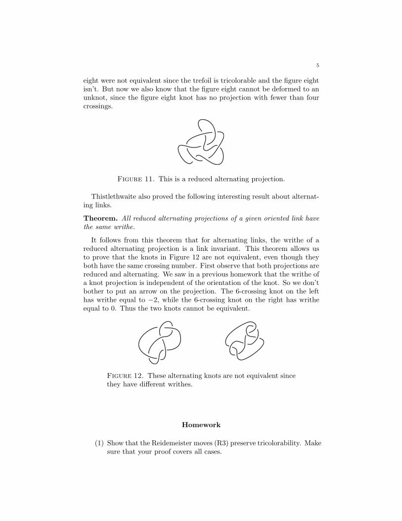
5
eight were not equivalent since the trefoil is tricolorable and the figure eightisn’t. But now we also know that the figure eight cannot be deformed to anunknot, since the figure eight knot has no projection with fewer than fourcrossings.
Figure 11. This is a reduced alternating projection.
Thistlethwaite also proved the following interesting result about alternat-ing links.
Theorem. All reduced alternating projections of a given oriented link havethe same writhe.
It follows from this theorem that for alternating links, the writhe of areduced alternating projection is a link invariant. This theorem allows usto prove that the knots in Figure 12 are not equivalent, even though theyboth have the same crossing number. First observe that both projections arereduced and alternating. We saw in a previous homework that the writhe ofa knot projection is independent of the orientation of the knot. So we don’tbother to put an arrow on the projection. The 6-crossing knot on the lefthas writhe equal to −2, while the 6-crossing knot on the right has writheequal to 0. Thus the two knots cannot be equivalent.
Figure 12. These alternating knots are not equivalent sincethey have different writhes.
Homework
(1) Show that the Reidemeister moves (R3) preserve tricolorability. Makesure that your proof covers all cases.
6
(2) Consider all of the seven crossing knots in the tables and determinewhich ones are tricolorable.
(3) Let K1 be a tricolorable knot and let K2 be any knot. Prove thatK1#K2 is tricolorable.
(4) Recall that c(L) is the smallest number of crossings that any projec-tion of a deformation of L can be drawn with. Prove that c(L) is alink invariant.
(5) Prove that there are no non-trivial knots with only two crossings.
(6) How many non-equivalent 2-component links are there having a pro-jection with two crossings? Justify your conclusion.
(7) Give an upper bound for the number of links there are with crossingnumber n (don’t try to find the least upper bound).
(8) Prove that for all knots K1 and K2, c(K1#K2) ≤ c(K1) + c(K2).
(9) Let K1 and K2 be knots. Prove that if K1 and K2 are alternatingthen c(K1#K2) = c(K1) + c(K2) Hint: first show that K1#K2 canbe deformed to an alternating projection.
(10) Let L denote an oriented link projection. Let L∗ denote the mirror
image of L. How is the writhe of L∗ related to the writhe of L? Can
the writhe ever be used to prove that a link is not equivalent to itsmirror image? Explain.
(11) Show that any knot projection can be changed to an alternatingprojection by changing a finite number of crossings. What is themaximum number of crossings that you have to change in an n-crossing projection to make it alternating? Explain.
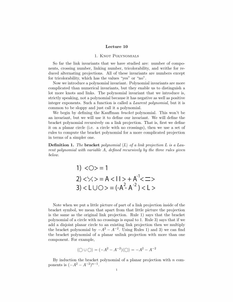
Lecture 10
1. Knot Polynomials
So far the link invariants that we have studied are: number of compo-nents, crossing number, linking number, tricolorability, and writhe for re-duced alternating projections. All of these invariants are numbers exceptfor tricolorability, which has the values “yes” or “no”.
Now we introduce a polynomial invariant. Polynomial invariants are morecomplicated than numerical invariants, but they enable us to distinguish alot more knots and links. The polynomial invariant that we introduce is,strictly speaking, not a polynomial because it has negative as well as positiveinteger exponents. Such a function is called a Laurent polynomial, but it iscommon to be sloppy and just call it a polynomial.
We begin by defining the Kauffman bracket polynomial. This won’t bean invariant, but we will use it to define our invariant. We will define thebracket polynomial recursively on a link projection. That is, first we defineit on a planar circle (i.e. a circle with no crossings), then we use a set ofrules to compute the bracket polynomial for a more complicated projectionin terms of a simpler one.
Definition 1. The bracket polynomial 〈L〉 of a link projection L is a Lau-
rent polynomial with variable A, defined recursively by the three rules given
below.
1) < > = 1
2) < > = A < I I > + A < >
3) < L > = (-A - A ) < L >-22
-1
∪
I I
Note when we put a little picture of part of a link projection inside of thebracket symbol, we mean that apart from that little picture the projectionis the same as the original link projection. Rule 1) says that the bracketpolynomial of a circle with no crossings is equal to 1. Rule 3) says that if weadd a disjoint planar circle to an existing link projection then we multiplythe bracket polynomial by −A2 − A−2. Using Rules 1) and 3) we can findthe bracket polynomial of a planar unlink projection with more than onecomponent. For example,
〈© ∪©〉 = (−A2 − A−2)〈©〉 = −A2 − A−2
By induction the bracket polynomial of a planar projection with n com-ponents is (−A2 − A−2)n−1.
1
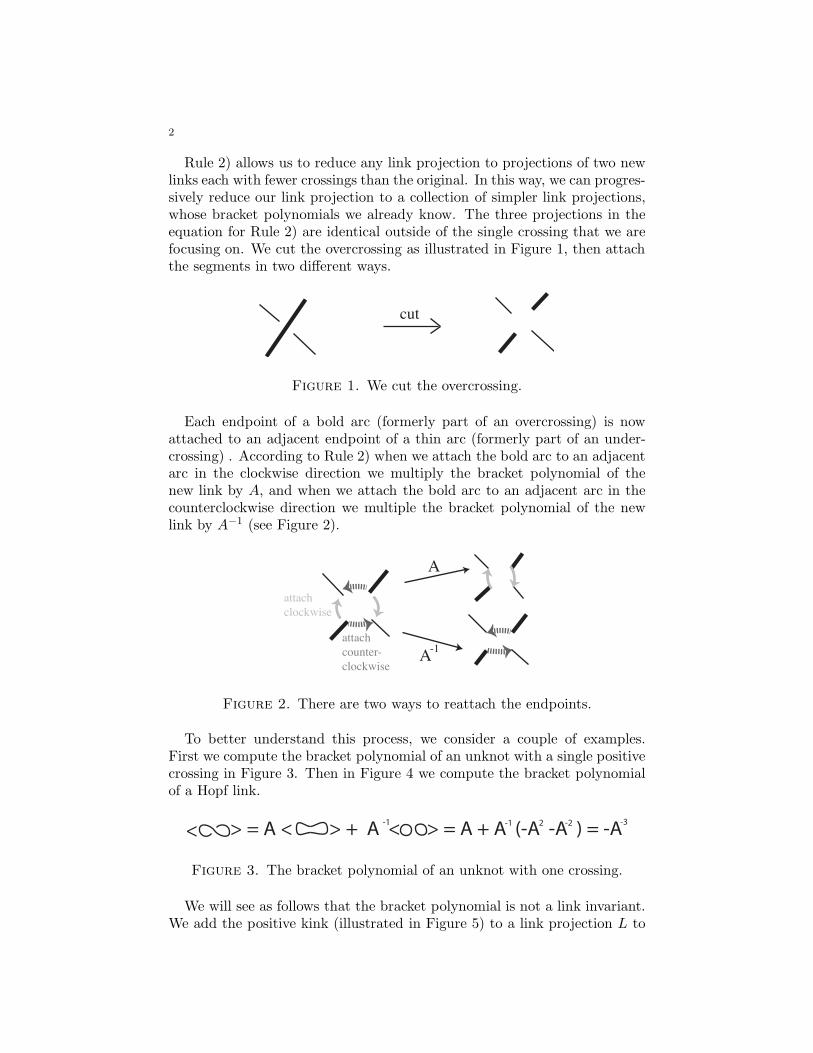
2
Rule 2) allows us to reduce any link projection to projections of two newlinks each with fewer crossings than the original. In this way, we can progres-sively reduce our link projection to a collection of simpler link projections,whose bracket polynomials we already know. The three projections in theequation for Rule 2) are identical outside of the single crossing that we arefocusing on. We cut the overcrossing as illustrated in Figure 1, then attachthe segments in two different ways.
cut
Figure 1. We cut the overcrossing.
Each endpoint of a bold arc (formerly part of an overcrossing) is nowattached to an adjacent endpoint of a thin arc (formerly part of an under-crossing) . According to Rule 2) when we attach the bold arc to an adjacentarc in the clockwise direction we multiply the bracket polynomial of thenew link by A, and when we attach the bold arc to an adjacent arc in thecounterclockwise direction we multiple the bracket polynomial of the newlink by A−1 (see Figure 2).
attach
clockwise
attach
counter-
clockwise
A
A-1
Figure 2. There are two ways to reattach the endpoints.
To better understand this process, we consider a couple of examples.First we compute the bracket polynomial of an unknot with a single positivecrossing in Figure 3. Then in Figure 4 we compute the bracket polynomialof a Hopf link.
< > = A < > + A < > = A + A (-A -A ) = -A-1 -1 -22 -3
Figure 3. The bracket polynomial of an unknot with one crossing.
We will see as follows that the bracket polynomial is not a link invariant.We add the positive kink (illustrated in Figure 5) to a link projection L to
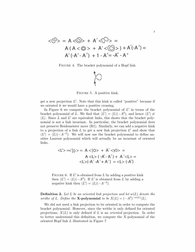
3
< > = A < > + A < > =
A ( A < > + A < > )
-1
-1
A (-A - A ) + 1 - A- 44
-1 -3
2 2 -2 - 4
+ A (-A ) =
= -A - A
Figure 4. The bracket polynomial of a Hopf link.
Figure 5. A positive kink.
get a new projection L′. Note that this kink is called “positive” because ifwe oriented it we would have a positive crossing.
In Figure 6 we compute the bracket polynomial of L′ in terms of thebracket polynomial of L. We find that 〈L′〉 = 〈L〉(−A3), and hence 〈L′〉 6=〈L〉. Since L and L′ are equivalent links, this shows that the bracket poly-nomial is not a link invariant. In particular, the bracket polynomial doesnot preserve Reidemeister move (R1). Similarly, we can add a negative kinkto a projection of a link L to get a new link projection L′ and show that〈L′〉 = 〈L〉(−A−3). We will now use the bracket polynomial to define an-other Laurent polynomial which will actually be an invariant of orientedlinks.
< > = A < > + A < > =
A <L> ( -A - A ) + A <L> =
-1
2
<L>(-A -A + A ) = <L> (-A )3-13
-2 -1
-1
<L’> =
Figure 6. If L′ is obtained from L by adding a positive kinkthen 〈L′〉 = 〈L〉(−A3). If L′ is obtained from L by adding anegative kink then 〈L′〉 = 〈L〉(−A−3).
Definition 2. Let L be an oriented link projection and let w(L) denote the
writhe of L. Define the X-polynomial to be X(L) = (−A3)−w(L)〈L〉.
We did not need a link projection to be oriented in order to compute thebracket polynomial. However, since the writhe is only defined for orientedprojections, X(L) is only defined if L is an oriented projection. In orderto better understand this definition, we compute the X-polynomial of theoriented Hopf link L illustrated in Figure 7
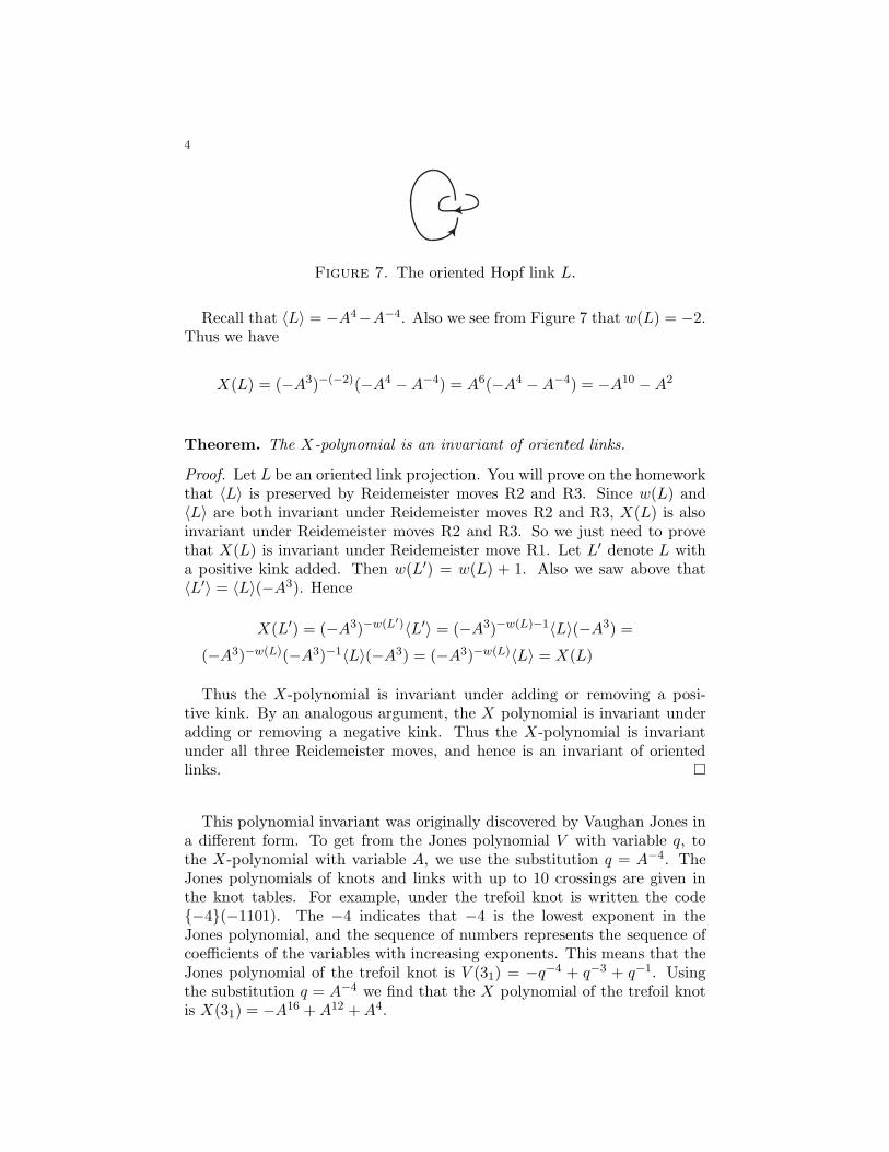
4
Figure 7. The oriented Hopf link L.
Recall that 〈L〉 = −A4−A−4. Also we see from Figure 7 that w(L) = −2.Thus we have
X(L) = (−A3)−(−2)(−A4 − A−4) = A6(−A4 − A−4) = −A10 − A2
Theorem. The X-polynomial is an invariant of oriented links.
Proof. Let L be an oriented link projection. You will prove on the homeworkthat 〈L〉 is preserved by Reidemeister moves R2 and R3. Since w(L) and〈L〉 are both invariant under Reidemeister moves R2 and R3, X(L) is alsoinvariant under Reidemeister moves R2 and R3. So we just need to provethat X(L) is invariant under Reidemeister move R1. Let L′ denote L witha positive kink added. Then w(L′) = w(L) + 1. Also we saw above that〈L′〉 = 〈L〉(−A3). Hence
X(L′) = (−A3)−w(L′)〈L′〉 = (−A3)−w(L)−1〈L〉(−A3) =
(−A3)−w(L)(−A3)−1〈L〉(−A3) = (−A3)−w(L)〈L〉 = X(L)
Thus the X-polynomial is invariant under adding or removing a posi-tive kink. By an analogous argument, the X polynomial is invariant underadding or removing a negative kink. Thus the X-polynomial is invariantunder all three Reidemeister moves, and hence is an invariant of orientedlinks. �
This polynomial invariant was originally discovered by Vaughan Jones ina different form. To get from the Jones polynomial V with variable q, tothe X-polynomial with variable A, we use the substitution q = A−4. TheJones polynomials of knots and links with up to 10 crossings are given inthe knot tables. For example, under the trefoil knot is written the code{−4}(−1101). The −4 indicates that −4 is the lowest exponent in theJones polynomial, and the sequence of numbers represents the sequence ofcoefficients of the variables with increasing exponents. This means that theJones polynomial of the trefoil knot is V (31) = −q−4 + q−3 + q−1. Usingthe substitution q = A−4 we find that the X polynomial of the trefoil knotis X(31) = −A16 + A12 + A4.
5
Homework
(1) Prove that the bracket polynomial is preserved by Reidemeistermoves R2 and R3.
(2) If L is an oriented link, then −L is the link with the orientation ofevery component reversed, and L∗ is the mirror image of L. Howis X(L) related to X(−L)? How is X(L∗) related to X(L)? Justifyyour conclusions.
(3) Compute the X polynomial of the trefoil knot, then use problem 2to show that the trefoil cannot be deformed to its mirror image.
(4) Use the Jones polynomials given in the knot tables to find a knotwith eight crossings which cannot be deformed to its mirror image.Explain your reasoning.
(5) Find an oriented link which cannot be deformed to it’s mirror image,yet has linking number zero. Explain how you know that your linkcannot be deformed to its mirror image.
(6) Let L+, L−, and L0 be three oriented link projections that are iden-tical outside of a crossing where the three links differ as indicatedbelow.
L L L0+ _
Follow the steps given below to prove the equation
q−1V (L+) − qV (L−) + (q−1
2 − q1
2 )V (L0) = 0
(a) First write equations for 〈L+〉 and 〈L−〉 in terms of the variableA.
(b) Use the equations from step (a) to get an equation relating 〈L+〉,〈L−〉, and 〈L0〉.
(c) Use the equation from step (b) to get an equation relatingX(L−), X(L+), and X(L0).
(d) Then use the substitution q = A−4 in the equation from step(c) to get the required equation.
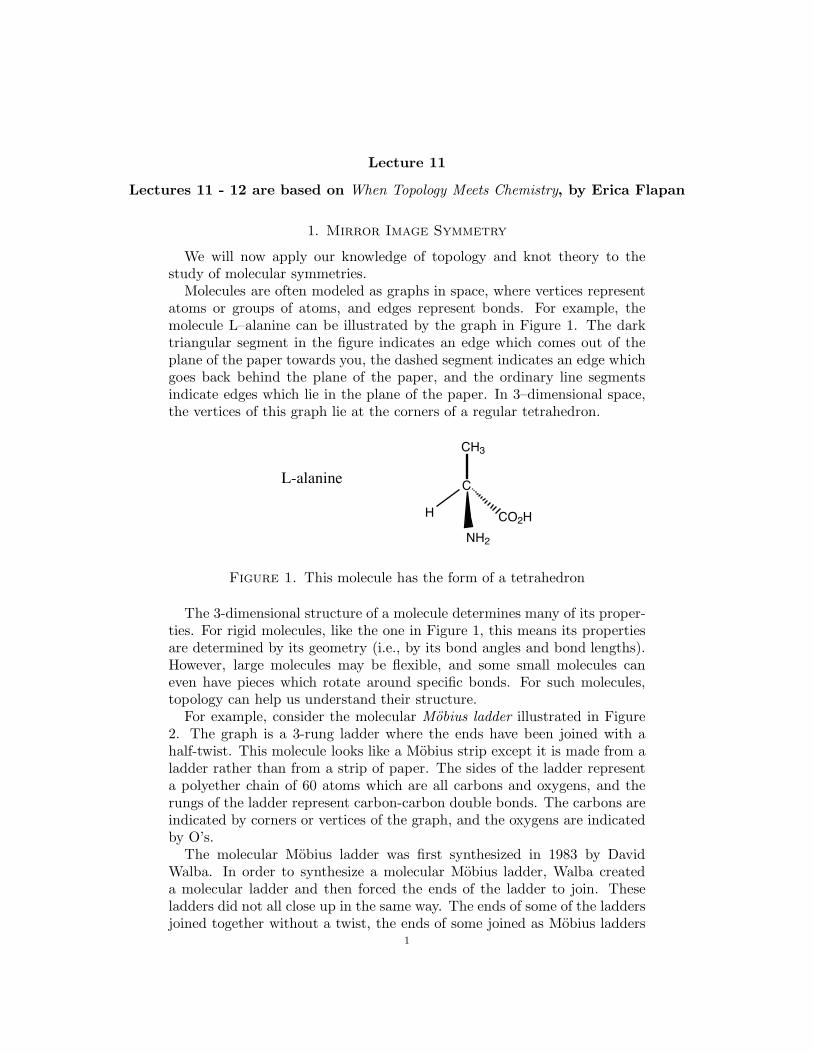
Lecture 11
Lectures 11 - 12 are based on When Topology Meets Chemistry, by Erica Flapan
1. Mirror Image Symmetry
We will now apply our knowledge of topology and knot theory to thestudy of molecular symmetries.
Molecules are often modeled as graphs in space, where vertices representatoms or groups of atoms, and edges represent bonds. For example, themolecule L–alanine can be illustrated by the graph in Figure 1. The darktriangular segment in the figure indicates an edge which comes out of theplane of the paper towards you, the dashed segment indicates an edge whichgoes back behind the plane of the paper, and the ordinary line segmentsindicate edges which lie in the plane of the paper. In 3–dimensional space,the vertices of this graph lie at the corners of a regular tetrahedron.
C
NH2
H
CH3
CO2H
L-alanine
Figure 1. This molecule has the form of a tetrahedron
The 3-dimensional structure of a molecule determines many of its proper-ties. For rigid molecules, like the one in Figure 1, this means its propertiesare determined by its geometry (i.e., by its bond angles and bond lengths).However, large molecules may be flexible, and some small molecules caneven have pieces which rotate around specific bonds. For such molecules,topology can help us understand their structure.
For example, consider the molecular Mobius ladder illustrated in Figure2. The graph is a 3-rung ladder where the ends have been joined with ahalf-twist. This molecule looks like a Mobius strip except it is made from aladder rather than from a strip of paper. The sides of the ladder representa polyether chain of 60 atoms which are all carbons and oxygens, and therungs of the ladder represent carbon-carbon double bonds. The carbons areindicated by corners or vertices of the graph, and the oxygens are indicatedby O’s.
The molecular Mobius ladder was first synthesized in 1983 by DavidWalba. In order to synthesize a molecular Mobius ladder, Walba createda molecular ladder and then forced the ends of the ladder to join. Theseladders did not all close up in the same way. The ends of some of the laddersjoined together without a twist, the ends of some joined as Mobius ladders
1
2
O
O
O O
O
O
O
O
OO
O
O
OO
O
O
O
O
Figure 2. The molecular Mobius ladder
with a left-handed half-twist, and the ends of others joined as Mobius lad-ders with a right-handed half-twist. Figure 3 illustrates a ladder whose endsare joined without a twist.
O
OO
OO
O O
O
O
OO
O
O
OO
OO
O
Figure 3. A molecular ladder in the form of a cylinder
Walba wanted to show that some of his ladders were Mobius ladders. Themolecules were too small to see in a microscope, so Walba needed some otherevidence to support his claim. He showed experimentally that some of hismolecules were distinct from their mirror image. A cylindrical ladder, is thesame as its mirror image, so not all of Walba’s molecules were cylindricalladders. Walba wanted to say that a molecular Mobius ladder is distinctfrom its mirror image. We illustrate the mirror image of Figure 2 in Figure4. The two figures are identical except for the crossing in the front.
O
O
O O
O
O
O
O
OO
O
O
OO
O
O
O
O
Figure 4. The mirror image of Figure 2
While Figure 4 looks different from Figure 2, it is not obvious that onestructure could not somehow change itself into the other. In particular,since the Mobius ladder is flexible, perhaps there is is some way it can bedeformed to its mirror image. In fact, if we do not distinguish the differenttypes of atoms and bonds, then a Mobius ladder can be deformed to itsmirror image. Figure 5 illustrates the Mobius ladder and its mirror imagewithout specifying the atoms or distinguishing the different types of atoms
3
or bonds. In the homework you will draw a deformation of one graph to theother.
Figure 5. A Mobius ladder and its mirror image withoutlabeling the atoms or bonds
If we are considering a molecular structure we cannot ignore the differ-ence between different types of atoms or different types of bonds. In 1983,the topologist, Jon Simon proved that if we distinguish between the differ-ent types of atoms, then the graph representing a molecular Mobius laddercannot be deformed to its mirror image. It follows that a molecular Mobiusladder cannot change into its mirror form.
Knowing that the molecular Mobius ladder is different from its mirrorimage was an important step in recognizing the form of the molecule. Ingeneral, knowing whether a molecular structure is the same or differentfrom its mirror image helps to predict its behavior. In order to refer to thisproperty, we make the following definition.
Definition 1. A molecule is said to be chemically achiral if it can changeinto its mirror image. Otherwise, it is said to be chemically chiral.
Chemists say that a molecule is “chiral” or “achiral”, rather than sayingthat it is “chemically chiral” or “chemically achiral.” We insert the word“chemically” in our definition in order to distinguish this type of chiralityfrom other types of chirality which we will introduce later. In particular, wewant to make it clear that this is an experimental rather than a mathematicaldefinition.
At first this definition may seem confusing because a molecule is chiral ifit is NOT the same as its mirror image and it is achiral if it IS the sameas its mirror image. Normally, we add the prefix “a” to a word to indicatethat something is not the case. For example, consider the words political andapolitical. The definition makes more sense if you understand its etymology.The word chiral comes from the ancient Greek word χειρ which means hand.A left hand can never change into a right hand. Thus a hand is an example ofa chiral object. So chiral really means “like a hand”, and achiral means “notlike a hand.” In fact, we often think of the two forms of a chiral molecule asthe left-handed form and the right-handed form.
Because biological organisms are chiral they react differently to the twoforms of another chiral molecule, just as my left foot reacts differently to aright shoe and a left shoe. For example, the molecule carvone is chiral. Oneform smells like spearmint and the mirror form smells like caraway because
4
the molecules in our olfactory systems are also chiral, and they are reactingto the carvone differently. It is believed that life cannot exist without chiralmolecules. In fact, scientists are looking for chiral molecules on other planetsas a sign of extraterrestrial life.
Pharmaceutical companies pay particular attention to chirality, becauseone form of a chiral medication is generally more effective while the mirrorform generally has more side effects. Most medications are synthesized ina 50:50 mix, and separating the two forms is expensive though for somemedications it is necessary. Also, sometimes when the two forms of a medi-cation are separated they each have a separate use. For example, Darvon isa painkiller, while its mirror form Novrad is used as a cough medicine.
Thus it is important to know whether or not a molecule is chiral, and ifit is chiral it may be useful to separate the two mirror forms. Chemists candetermine experimentally whether or not a particular molecule is chemicallychiral (as Walba did). But suppose a chemist is designing a new molecule,and wants to know before it is synthesized whether the molecule will bechiral. To do this, chemists generally use a geometric notion of chirality.Lord Kelvin, Professor of Natural Philosophy at the University of Glasgow,introduced this concept in 1884.
“I call any geometrical figure, or group of points chiral, andsay it has chirality, if its image in a plane mirror, ideallyrealized, cannot be brought to coincide with itself.”
In other words, a structure is considered to be a rigid object and it issaid to be chiral if it is different from its mirror image. For example, themolecule illustrated in Figure 1 is chiral because it’s different from its mirrorimage. Modern organic chemistry textbooks often paraphrase Lord Kelvin’sdefinition as follows.
Definition 2. A chiral molecule is one that is not superimposable with itsmirror image.
This definition assumes that all molecules are rigid. We shall use thefollowing definition which restates the above definition more mathematically.
Definition 3. A structure is said to be geometrically achiral if, as arigid object, it is identical with its mirror image. Otherwise, it is said to begeometrically chiral.
Chemists use the word “chirality” for both geometric chirality and chem-ical chirality, because they consider these concepts to be interchangeable.However, these two concepts are not equivalent. For example, a right-handedglove is a geometrically chiral object, because as a rigid object it cannot besuperimposed on a left-handed glove. Yet, if the glove is flexible (as a knit-ted or rubber glove is), then it can be turned inside out to get a left-handed
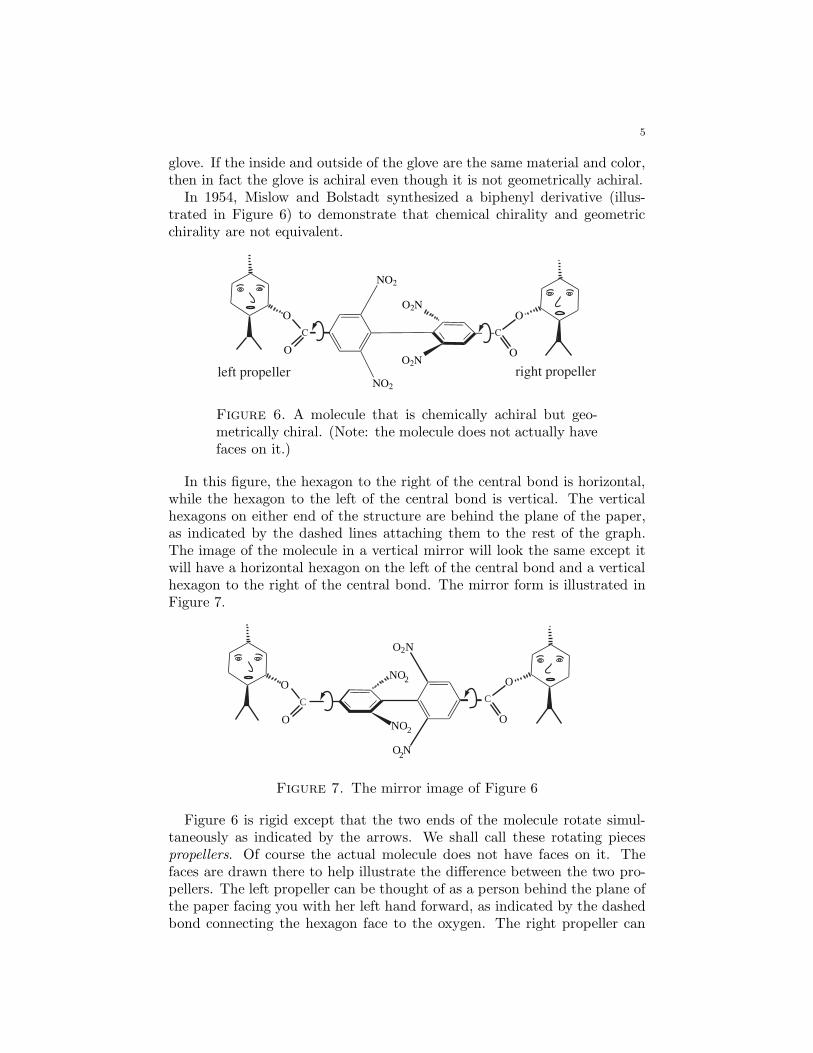
5
glove. If the inside and outside of the glove are the same material and color,then in fact the glove is achiral even though it is not geometrically achiral.
In 1954, Mislow and Bolstadt synthesized a biphenyl derivative (illus-trated in Figure 6) to demonstrate that chemical chirality and geometricchirality are not equivalent.
NO2
O
NO2
O2N
OO2N
O
C C
O
left propeller right propeller
Figure 6. A molecule that is chemically achiral but geo-metrically chiral. (Note: the molecule does not actually havefaces on it.)
In this figure, the hexagon to the right of the central bond is horizontal,while the hexagon to the left of the central bond is vertical. The verticalhexagons on either end of the structure are behind the plane of the paper,as indicated by the dashed lines attaching them to the rest of the graph.The image of the molecule in a vertical mirror will look the same except itwill have a horizontal hexagon on the left of the central bond and a verticalhexagon to the right of the central bond. The mirror form is illustrated inFigure 7.
NO
NO2
2
O2N
O2N
O
O
C
O
C
O
Figure 7. The mirror image of Figure 6
Figure 6 is rigid except that the two ends of the molecule rotate simul-taneously as indicated by the arrows. We shall call these rotating piecespropellers. Of course the actual molecule does not have faces on it. Thefaces are drawn there to help illustrate the difference between the two pro-pellers. The left propeller can be thought of as a person behind the plane ofthe paper facing you with her left hand forward, as indicated by the dashedbond connecting the hexagon face to the oxygen. The right propeller can
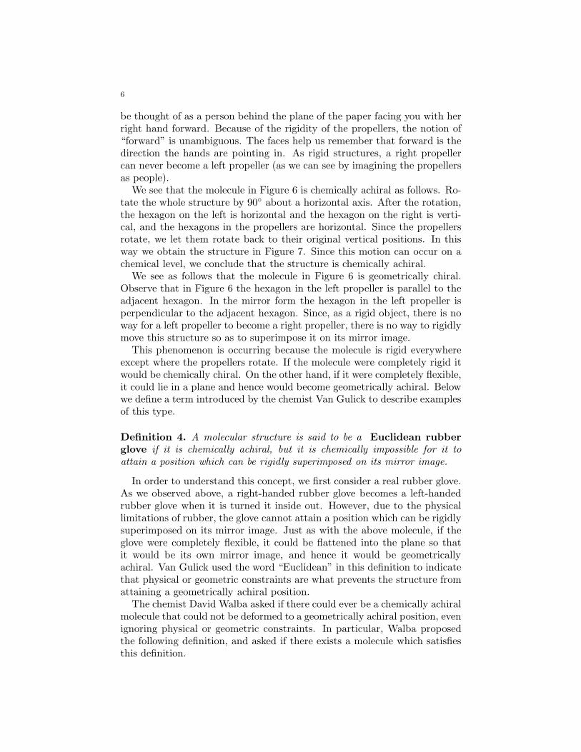
6
be thought of as a person behind the plane of the paper facing you with herright hand forward. Because of the rigidity of the propellers, the notion of“forward” is unambiguous. The faces help us remember that forward is thedirection the hands are pointing in. As rigid structures, a right propellercan never become a left propeller (as we can see by imagining the propellersas people).
We see that the molecule in Figure 6 is chemically achiral as follows. Ro-tate the whole structure by 90◦ about a horizontal axis. After the rotation,the hexagon on the left is horizontal and the hexagon on the right is verti-cal, and the hexagons in the propellers are horizontal. Since the propellersrotate, we let them rotate back to their original vertical positions. In thisway we obtain the structure in Figure 7. Since this motion can occur on achemical level, we conclude that the structure is chemically achiral.
We see as follows that the molecule in Figure 6 is geometrically chiral.Observe that in Figure 6 the hexagon in the left propeller is parallel to theadjacent hexagon. In the mirror form the hexagon in the left propeller isperpendicular to the adjacent hexagon. Since, as a rigid object, there is noway for a left propeller to become a right propeller, there is no way to rigidlymove this structure so as to superimpose it on its mirror image.
This phenomenon is occurring because the molecule is rigid everywhereexcept where the propellers rotate. If the molecule were completely rigid itwould be chemically chiral. On the other hand, if it were completely flexible,it could lie in a plane and hence would become geometrically achiral. Belowwe define a term introduced by the chemist Van Gulick to describe examplesof this type.
Definition 4. A molecular structure is said to be a Euclidean rubber
glove if it is chemically achiral, but it is chemically impossible for it toattain a position which can be rigidly superimposed on its mirror image.
In order to understand this concept, we first consider a real rubber glove.As we observed above, a right-handed rubber glove becomes a left-handedrubber glove when it is turned it inside out. However, due to the physicallimitations of rubber, the glove cannot attain a position which can be rigidlysuperimposed on its mirror image. Just as with the above molecule, if theglove were completely flexible, it could be flattened into the plane so thatit would be its own mirror image, and hence it would be geometricallyachiral. Van Gulick used the word “Euclidean” in this definition to indicatethat physical or geometric constraints are what prevents the structure fromattaining a geometrically achiral position.
The chemist David Walba asked if there could ever be a chemically achiralmolecule that could not be deformed to a geometrically achiral position, evenignoring physical or geometric constraints. In particular, Walba proposedthe following definition, and asked if there exists a molecule which satisfiesthis definition.
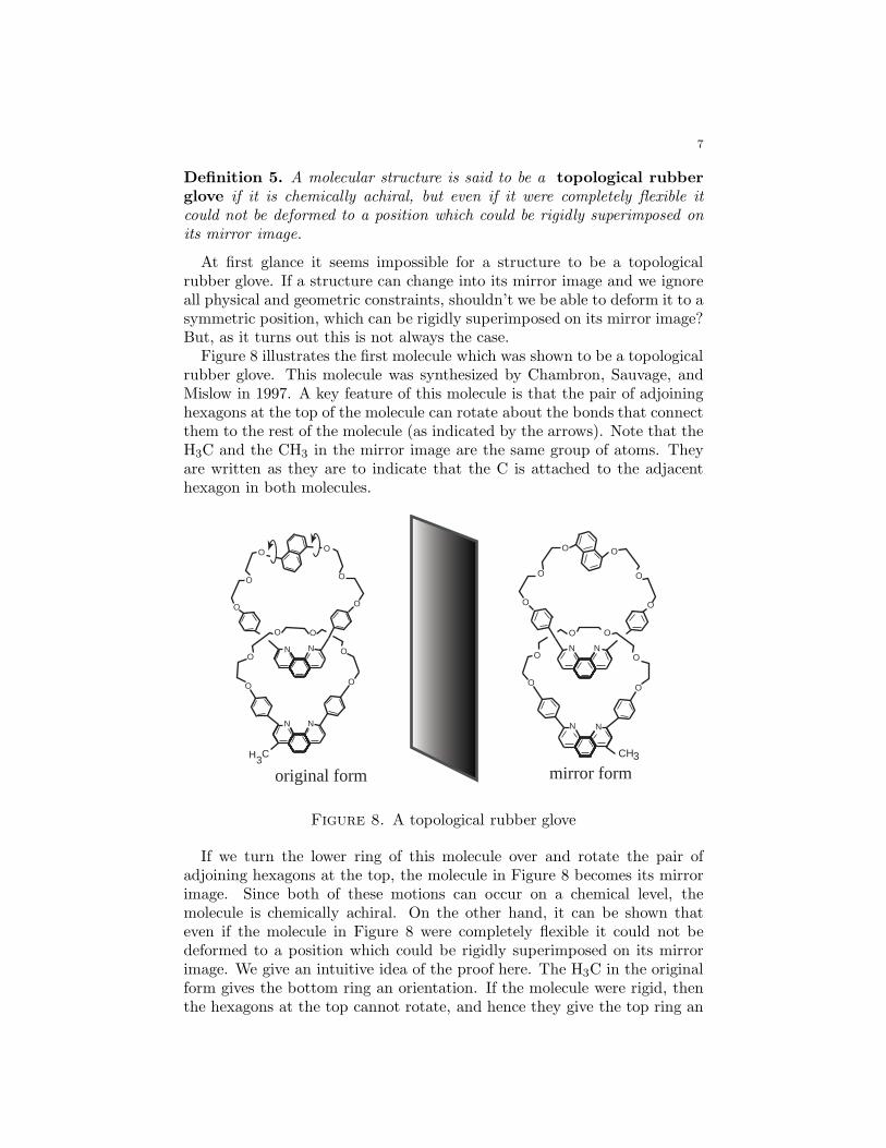
7
Definition 5. A molecular structure is said to be a topological rubber
glove if it is chemically achiral, but even if it were completely flexible itcould not be deformed to a position which could be rigidly superimposed onits mirror image.
At first glance it seems impossible for a structure to be a topologicalrubber glove. If a structure can change into its mirror image and we ignoreall physical and geometric constraints, shouldn’t we be able to deform it to asymmetric position, which can be rigidly superimposed on its mirror image?But, as it turns out this is not always the case.
Figure 8 illustrates the first molecule which was shown to be a topologicalrubber glove. This molecule was synthesized by Chambron, Sauvage, andMislow in 1997. A key feature of this molecule is that the pair of adjoininghexagons at the top of the molecule can rotate about the bonds that connectthem to the rest of the molecule (as indicated by the arrows). Note that theH3C and the CH3 in the mirror image are the same group of atoms. Theyare written as they are to indicate that the C is attached to the adjacenthexagon in both molecules.
N N
O
O
OO
O
O
CH3
N N
O
O
OO
O
O
N N
O
O
O O
O
O
H3C
N N
O
O
O O
O
O
original form mirror form
Figure 8. A topological rubber glove
If we turn the lower ring of this molecule over and rotate the pair ofadjoining hexagons at the top, the molecule in Figure 8 becomes its mirrorimage. Since both of these motions can occur on a chemical level, themolecule is chemically achiral. On the other hand, it can be shown thateven if the molecule in Figure 8 were completely flexible it could not bedeformed to a position which could be rigidly superimposed on its mirrorimage. We give an intuitive idea of the proof here. The H3C in the originalform gives the bottom ring an orientation. If the molecule were rigid, thenthe hexagons at the top cannot rotate, and hence they give the top ring an
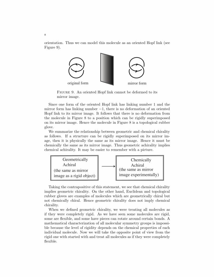
8
orientation. Thus we can model this molecule as an oriented Hopf link (seeFigure 9).
original form mirror form
Figure 9. An oriented Hopf link cannot be deformed to itsmirror image.
Since one form of the oriented Hopf link has linking number 1 and themirror form has linking number −1, there is no deformation of an orientedHopf link to its mirror image. It follows that there is no deformation fromthe molecule in Figure 8 to a position which can be rigidly superimposedon its mirror image. Hence the molecule in Figure 8 is a topological rubberglove.
We summarize the relationship between geometric and chemical chiralityas follows. If a structure can be rigidly superimposed on its mirror im-age, then it is physically the same as its mirror image. Hence it must bechemically the same as its mirror image. Thus geometric achirality implieschemical achirality. It may be easier to remember with a picture.
Geometrically
AchiralChemically
Achiral
(the same as mirror
image as a rigid object)
(the same as mirror
image experimentally)
Taking the contrapositive of this statement, we see that chemical chiralityimplies geometric chirality. On the other hand, Euclidean and topologicalrubber gloves are examples of molecules which are geometrically chiral butnot chemically chiral. Hence geometric chirality does not imply chemicalchirality.
When we defined geometric chirality, we were treating all molecules asif they were completely rigid. As we have seen some molecules are rigid,some are flexible, and some have pieces can rotate around certain bonds. Amathematical characterization of all molecular symmetry groups is impossi-ble because the level of rigidity depends on the chemical properties of eachindividual molecule. Now we will take the opposite point of view from therigid one with started with and treat all molecules as if they were completelyflexible.
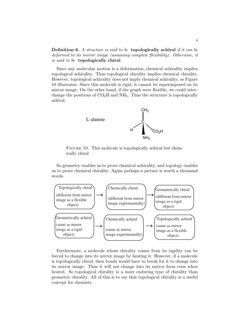
9
Definition 6. A structure is said to be topologically achiral if it can bedeformed to its mirror image (assuming complete flexibility). Otherwise, itis said to be topologically chiral.
Since any molecular motion is a deformation, chemical achirality impliestopological achirality. Thus topological chirality implies chemical chirality.However, topological achirality does not imply chemical achirality, as Figure10 illustrates. Since this molecule is rigid, it cannot be superimposed on itsmirror image. On the other hand, if the graph were flexible, we could inter-change the positions of CO2H and NH2. Thus the structure is topologicallyachiral.
C
NH2
H
CH3
CO2H
L-alanine
Figure 10. This molecule is topologically achiral but chem-ically chiral
So geometry enables us to prove chemical achirality, and topology enablesus to prove chemical chirality. Again perhaps a picture is worth a thousandwords.
Topologically chiralGeometrically chiral
(different from mirror
image as a rigid
object)
(different from mirror
image experimentally)
(different from mirror
image as a flexible
object)
Chemically chiral
Geometrically achiral
(same as mirror
image as a rigid
object)
(same as mirror
image experimentally)
Chemically achiral Topologically achiral
(same as mirror
image as a flexible
object)
Furthermore, a molecule whose chirality comes from its rigidity can beforced to change into its mirror image by heating it. However, if a moleculeis topologically chiral, then bonds would have to break for it to change intoits mirror image. Thus it will not change into its mirror form even whenheated. So topological chirality is a more enduring type of chirality thangeometric chirality. All of this is to say that topological chirality is a usefulconcept for chemists.
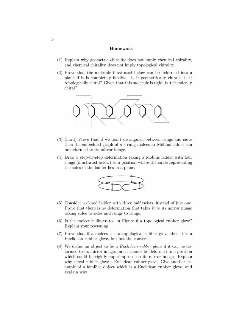
10
Homework
(1) Explain why geometric chirality does not imply chemical chirality,and chemical chirality does not imply topological chirality.
(2) Prove that the molecule illustrated below can be deformed into aplane if it is completely flexible. Is it geometrically chiral? Is ittopologically chiral? Given that this molecule is rigid, is it chemicallychiral?
(3) (hard) Prove that if we don’t distinguish between rungs and sidesthen the embedded graph of a 3-rung molecular Mobius ladder canbe deformed to its mirror image.
(4) Draw a step-by-step deformation taking a Mobius ladder with fourrungs (illustrated below) to a position where the circle representingthe sides of the ladder lies in a plane.
(5) Consider a closed ladder with three half twists, instead of just one.Prove that there is no deformation that takes it to its mirror imagetaking sides to sides and rungs to rungs.
(6) Is the molecule illustrated in Figure 6 a topological rubber glove?Explain your reasoning.
(7) Prove that if a molecule is a topological rubber glove then it is aEuclidean rubber glove, but not the converse.
(8) We define an object to be a Euclidean rubber glove if it can be de-formed to its mirror image, but it cannot be deformed to a positionwhich could be rigidly superimposed on its mirror image. Explainwhy a real rubber glove a Euclidean rubber glove. Give another ex-ample of a familiar object which is a Euclidean rubber glove, andexplain why.
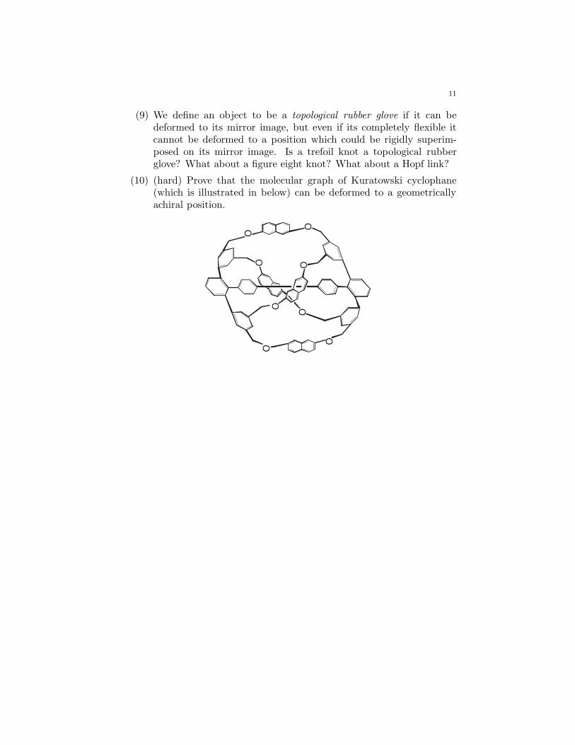
11
(9) We define an object to be a topological rubber glove if it can bedeformed to its mirror image, but even if its completely flexible itcannot be deformed to a position which could be rigidly superim-posed on its mirror image. Is a trefoil knot a topological rubberglove? What about a figure eight knot? What about a Hopf link?
(10) (hard) Prove that the molecular graph of Kuratowski cyclophane(which is illustrated in below) can be deformed to a geometricallyachiral position.
O
OO
O
O
O
O
O
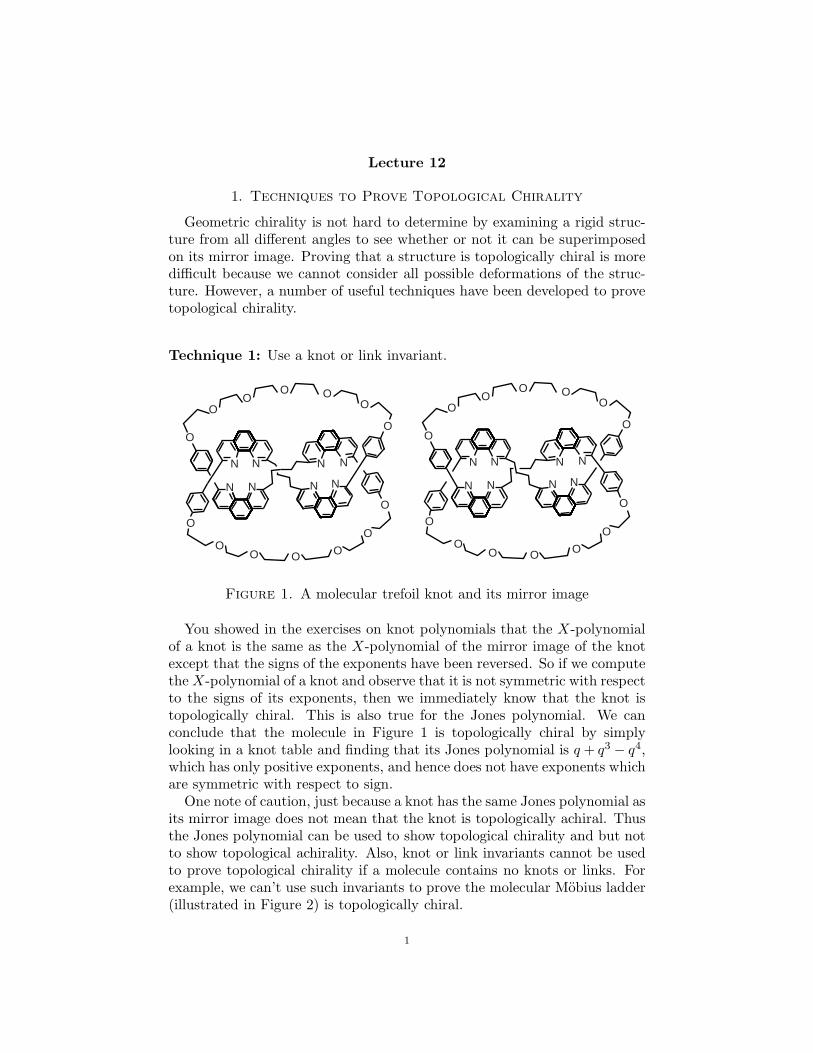
Lecture 12
1. Techniques to Prove Topological Chirality
Geometric chirality is not hard to determine by examining a rigid struc-ture from all different angles to see whether or not it can be superimposedon its mirror image. Proving that a structure is topologically chiral is moredifficult because we cannot consider all possible deformations of the struc-ture. However, a number of useful techniques have been developed to provetopological chirality.
Technique 1: Use a knot or link invariant.
N
OOO
OO
OO
O
OO O O
O
O
N N N
NNNN
N
OOO
OO
OO
O
OO O O
O
O
N N N
NNNN
Figure 1. A molecular trefoil knot and its mirror image
You showed in the exercises on knot polynomials that the X-polynomialof a knot is the same as the X-polynomial of the mirror image of the knotexcept that the signs of the exponents have been reversed. So if we computethe X-polynomial of a knot and observe that it is not symmetric with respectto the signs of its exponents, then we immediately know that the knot istopologically chiral. This is also true for the Jones polynomial. We canconclude that the molecule in Figure 1 is topologically chiral by simplylooking in a knot table and finding that its Jones polynomial is q + q3
− q4,which has only positive exponents, and hence does not have exponents whichare symmetric with respect to sign.
One note of caution, just because a knot has the same Jones polynomial asits mirror image does not mean that the knot is topologically achiral. Thusthe Jones polynomial can be used to show topological chirality and but notto show topological achirality. Also, knot or link invariants cannot be usedto prove topological chirality if a molecule contains no knots or links. Forexample, we can’t use such invariants to prove the molecular Mobius ladder(illustrated in Figure 2) is topologically chiral.
1
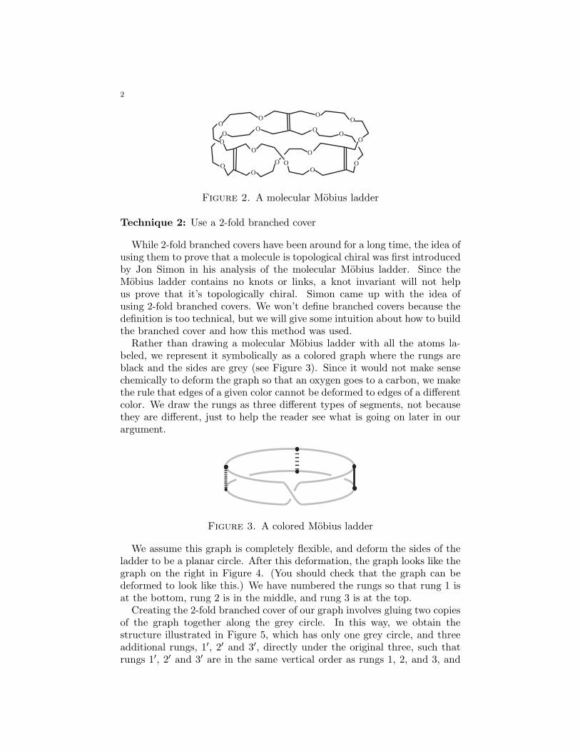
2
O
O
O O
O
O
O
O
OO
O
O
OO
O
O
O
O
Figure 2. A molecular Mobius ladder
Technique 2: Use a 2-fold branched cover
While 2-fold branched covers have been around for a long time, the idea ofusing them to prove that a molecule is topological chiral was first introducedby Jon Simon in his analysis of the molecular Mobius ladder. Since theMobius ladder contains no knots or links, a knot invariant will not helpus prove that it’s topologically chiral. Simon came up with the idea ofusing 2-fold branched covers. We won’t define branched covers because thedefinition is too technical, but we will give some intuition about how to buildthe branched cover and how this method was used.
Rather than drawing a molecular Mobius ladder with all the atoms la-beled, we represent it symbolically as a colored graph where the rungs areblack and the sides are grey (see Figure 3). Since it would not make sensechemically to deform the graph so that an oxygen goes to a carbon, we makethe rule that edges of a given color cannot be deformed to edges of a differentcolor. We draw the rungs as three different types of segments, not becausethey are different, just to help the reader see what is going on later in ourargument.
Figure 3. A colored Mobius ladder
We assume this graph is completely flexible, and deform the sides of theladder to be a planar circle. After this deformation, the graph looks like thegraph on the right in Figure 4. (You should check that the graph can bedeformed to look like this.) We have numbered the rungs so that rung 1 isat the bottom, rung 2 is in the middle, and rung 3 is at the top.
Creating the 2-fold branched cover of our graph involves gluing two copiesof the graph together along the grey circle. In this way, we obtain thestructure illustrated in Figure 5, which has only one grey circle, and threeadditional rungs, 1′, 2′ and 3′, directly under the original three, such thatrungs 1′, 2′ and 3′ are in the same vertical order as rungs 1, 2, and 3, and
3
12
3
1
2
3
Figure 4. A colored Mobius ladder with planar sides andnumbered rungs
1’
1
2’
2
3’
3
Figure 5. The 2-fold branched cover of the Mobius ladder
rung 1′ has the same endpoints as rung 1, rung 2′ has the same endpointsas rung 2, and rung 3′ has the same endpoints as rung 3.
If we erase the grey circle from Figure 5 we obtain a link with threecomponents, which has the property that each component of the link islinked to each of the other components (see Figure 6). Simon proved thatthis link is topologically chiral by using the linking number. This requiresconsidering cases according to what orientation we put on each component.Now the topological chirality of this link implies that the colored Mobiusladder must be topologically chiral. Hence the molecular Mobius ladder isalso topologically chiral.
Technique 3: Find a unique Mobius ladder in the molecule.
This method was developed by the chemist Kurt Mislow to prove thatthe molecule triple layered naphthalenophane (illustrated in Figure 7) wastopologically chiral.
We illustrate triple layered naphthalenophane in Figure 7. A naphthaleneconsists of a pair of hexagons, and is the primary ingredient in mothballs.We see that this molecule does indeed have three layers of naphthalene.
A key observation that we use is that the graph of triple layered naph-thalenophane contains a unique circuit that is longer than any other circuit
4
Figure 6. If we erase the grey circle in Figure 5 then wehave this link.
Figure 7. Triple layered naphthalenophane
in the graph. In Figure 8, we have illustrated this longest circuit. Youshould check that this circuit is indeed longer than any other circuit in thegraph.
C
Figure 8. The unique longest circuit in triple layered naphthalenophane
The three vertical edges in the center of the graph are the only edgeswhich have both endpoints on this unique circuit. In Figure 9, we illustratethe unique circuit together with these three edges (without the additionaledges at the top and bottom of the figure).
5
Figure 9. The longest circuit together with the three edgeswhose vertices are on the circuit
Suppose, for the sake of contradiction, that the graph of triple layerednaphthalenophane can be deformed to its mirror image. Such a deformationwould take the colored graph in Figure 9 to its mirror image. However,Figure 9 can be deformed to a colored Mobius ladder, which we know istopologically chiral. Hence such a deformation is not possible. Therefore,triple layered naphthalenophane must be topologically chiral.
Technique 4: A combinatorial approach
The following method focuses on the structure of the graph, rather thanthe way the graph is embedded in 3-dimensional space. We begin withseveral definitions.
Definition 1. An automorphism of a graph is a permutation of the
vertices which takes adjacent vertices to adjacent vertices. For molecular
graphs an automorphism is also required to take atoms of a given type to
atoms of the same type.
For example, consider the Mobius ladder illustrated in Figure 10. We havenumbered the vertices to make it easier to describe a particular permutationof the vertices. The permutation which interchanges vertices 2 and 6 andinterchanges vertices 3 and 5 is an automorphism. On the other hand, thepermutation which just interchanges vertices 2 and 5 is not an automorphismbecause vertex 2 is adjacent to vertex 3, while vertex 5 is not adjacent tovertex 3.
12
3
4
5
6
Figure 10. The permuation which interchanges vertices 2and 6 and vertices 3 and 5 is an automorphism
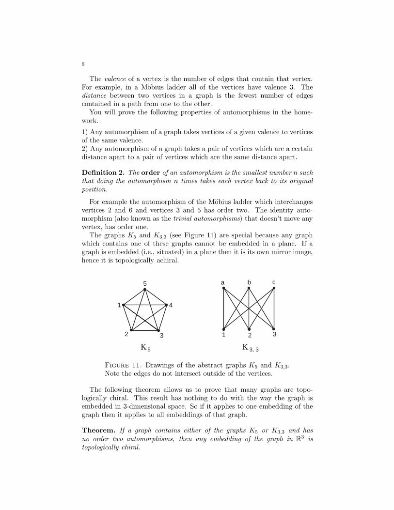
6
The valence of a vertex is the number of edges that contain that vertex.For example, in a Mobius ladder all of the vertices have valence 3. Thedistance between two vertices in a graph is the fewest number of edgescontained in a path from one to the other.
You will prove the following properties of automorphisms in the home-work.
1) Any automorphism of a graph takes vertices of a given valence to verticesof the same valence.2) Any automorphism of a graph takes a pair of vertices which are a certaindistance apart to a pair of vertices which are the same distance apart.
Definition 2. The order of an automorphism is the smallest number n such
that doing the automorphism n times takes each vertex back to its original
position.
For example the automorphism of the Mobius ladder which interchangesvertices 2 and 6 and vertices 3 and 5 has order two. The identity auto-morphism (also known as the trivial automorphisms) that doesn’t move anyvertex, has order one.
The graphs K5 and K3,3 (see Figure 11) are special because any graphwhich contains one of these graphs cannot be embedded in a plane. If agraph is embedded (i.e., situated) in a plane then it is its own mirror image,hence it is topologically achiral.
1
2
4
3
5 a b c
1 2 3
K K 3, 35
Figure 11. Drawings of the abstract graphs K5 and K3,3.Note the edges do not intersect outside of the vertices.
The following theorem allows us to prove that many graphs are topo-logically chiral. This result has nothing to do with the way the graph isembedded in 3-dimensional space. So if it applies to one embedding of thegraph then it applies to all embeddings of that graph.
Theorem. If a graph contains either of the graphs K5 or K3,3 and has
no order two automorphisms, then any embedding of the graph in R3 is
topologically chiral.
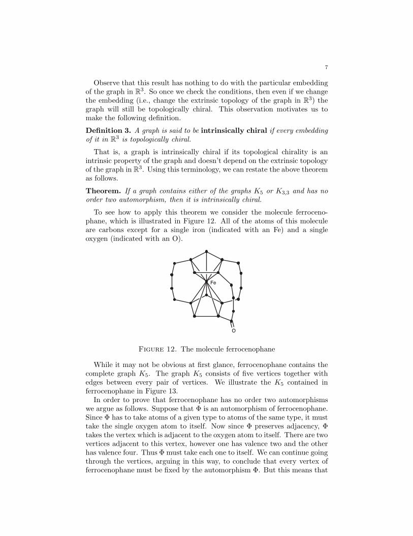
7
Observe that this result has nothing to do with the particular embeddingof the graph in R
3. So once we check the conditions, then even if we changethe embedding (i.e., change the extrinsic topology of the graph in R
3) thegraph will still be topologically chiral. This observation motivates us tomake the following definition.
Definition 3. A graph is said to be intrinsically chiral if every embedding
of it in R3 is topologically chiral.
That is, a graph is intrinsically chiral if its topological chirality is anintrinsic property of the graph and doesn’t depend on the extrinsic topologyof the graph in R
3. Using this terminology, we can restate the above theoremas follows.
Theorem. If a graph contains either of the graphs K5 or K3,3 and has no
order two automorphism, then it is intrinsically chiral.
To see how to apply this theorem we consider the molecule ferroceno-phane, which is illustrated in Figure 12. All of the atoms of this moleculeare carbons except for a single iron (indicated with an Fe) and a singleoxygen (indicated with an O).
O
Fe
Figure 12. The molecule ferrocenophane
While it may not be obvious at first glance, ferrocenophane contains thecomplete graph K5. The graph K5 consists of five vertices together withedges between every pair of vertices. We illustrate the K5 contained inferrocenophane in Figure 13.
In order to prove that ferrocenophane has no order two automorphismswe argue as follows. Suppose that Φ is an automorphism of ferrocenophane.Since Φ has to take atoms of a given type to atoms of the same type, it musttake the single oxygen atom to itself. Now since Φ preserves adjacency, Φtakes the vertex which is adjacent to the oxygen atom to itself. There are twovertices adjacent to this vertex, however one has valence two and the otherhas valence four. Thus Φ must take each one to itself. We can continue goingthrough the vertices, arguing in this way, to conclude that every vertex offerrocenophane must be fixed by the automorphism Φ. But this means that
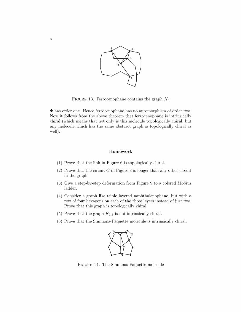
8
1 2
3
4
5
Figure 13. Ferrocenophane contains the graph K5
Φ has order one. Hence ferrocenophane has no automorphism of order two.Now it follows from the above theorem that ferrocenophane is intrinsicallychiral (which means that not only is this molecule topologically chiral, butany molecule which has the same abstract graph is topologically chiral aswell).
Homework
(1) Prove that the link in Figure 6 is topologically chiral.
(2) Prove that the circuit C in Figure 8 is longer than any other circuitin the graph.
(3) Give a step-by-step deformation from Figure 9 to a colored Mobiusladder.
(4) Consider a graph like triple layered naphthalenophane, but with arow of four hexagons on each of the three layers instead of just two.Prove that this graph is topologically chiral.
(5) Prove that the graph K3,3 is not intrinsically chiral.
(6) Prove that the Simmons-Paquette molecule is intrinsically chiral.
OO O
Figure 14. The Simmons-Paquette molecule
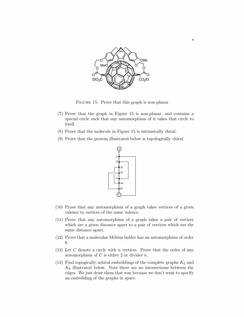
9
Figure 15. Prove that this graph is non-planar
(7) Prove that the graph in Figure 15 is non-planar, and contains aspecial circle such that any automorphism of it takes that circle toitself.
(8) Prove that the molecule in Figure 15 is intrinsically chiral.
(9) Prove that the protein illustrated below is topologically chiral.
N
C
12
16
25
29
41
46
48
(10) Prove that any automorphism of a graph takes vertices of a givenvalence to vertices of the same valence.
(11) Prove that any automorphism of a graph takes a pair of verticeswhich are a given distance apart to a pair of vertices which are thesame distance apart.
(12) Prove that a molecular Mobius ladder has an automorphism of order6.
(13) Let C denote a circle with n vertices. Prove that the order of anyautomorphism of C is either 2 or divides n.
(14) Find topogically achiral embeddings of the complete graphs K5 andK6 illustrated below. Note there are no intersections between theedges. We just draw them that way because we don’t want to specifyan embedding of the graphs in space.
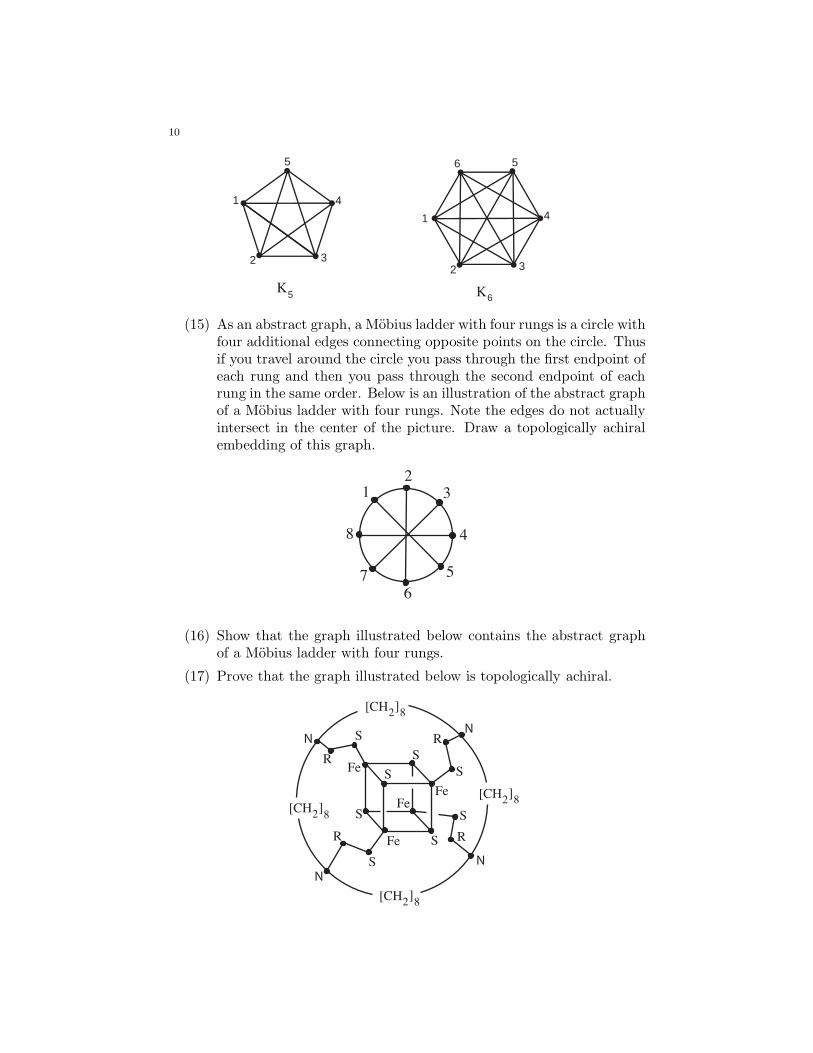
10
1
2
4
3
5
K5
1
2 3
4
5
5
6
K6
(15) As an abstract graph, a Mobius ladder with four rungs is a circle withfour additional edges connecting opposite points on the circle. Thusif you travel around the circle you pass through the first endpoint ofeach rung and then you pass through the second endpoint of eachrung in the same order. Below is an illustration of the abstract graphof a Mobius ladder with four rungs. Note the edges do not actuallyintersect in the center of the picture. Draw a topologically achiralembedding of this graph.
12
3
4
5
6
7
8
(16) Show that the graph illustrated below contains the abstract graphof a Mobius ladder with four rungs.
(17) Prove that the graph illustrated below is topologically achiral.
[CH2]8
[CH2]8
[CH2]8
[CH2]8
N
N
N
N
R
S
Fe
R
S
Fe
S
S
SR
S
Fe
S
R
Fe
S