Embed Size (px)
Citation preview

Lecture 10: DataLink 1
Introduction To Computer Networks
-89מבוא לרשתות תקשורת 350Ethernet and Switches פרופ' אמיר הרצברג
Computer Networking: A Top Down Approach Featuring the Internet, 3rd edition. Jim Kurose, Keith RossAddison-Wesley, July 2005. ** Group purchase ?? **
Based on foils by Kurose & Ross ©, see: http://www.aw.com/kurose-ross/
My site: http://AmirHerzberg.com
Course site http://www.cs.biu.ac.il/~89-350/

Lecture 10: DataLink 2
Agenda: link layer technologies: Ethernet Hubs, bridges, switches, etc… A bit about:
wireless (IEEE 802.11 LANs) PPP ATM Frame Relay

Lecture 10: DataLink 3
Ethernet: “dominant” wired LAN technology, using CSMA/CD: Simple, cheap and familiar (first widely used LAN) IP-friendly
Unreliable, connectionless service
Speed/cost options: 10, 100, 1000 Mbps Max cable (segment) length options: 100m to 5000m
Metcalfe’s EthernetSketch; think of `Ether` as a single cable (segment)

Lecture 10: DataLink 4
Ethernet Frame Structure
Preamble (8 Bytes): “AA AA AA AA AA AA AA AB” used to synchronize receiver, sender clock rates
MAC Addresses (6 Bytes): Pass to net-layer packets (data) from frames with matching
and broadcast addresses; ignore others
Type/Length (2 Bytes): protocol or length: see next... CRC(4 Bytes): checked at receiver, if error is
detected, the frame is simply dropped Data: 46 to 1500 Bytes (if shorter: add pad)
Why? Maximal: small buffer; Minimal: see soon…
(or length)

Lecture 10: DataLink 5
Type or Length?
Two (main) flavors of Ethernet formats IEEE 802.3 `Standard Ethernet`: Length
Up to 1500 (max length) Identify higher-layer by LLC header (in data)
Ethernet II (DIX): Type Use these 2 bytes to identify higher-layer
protocol (e.g. IPv4=0800) All identifiers > 1500 Identify end of data by CRC hardware
outputting 00-00-00-00
(or length)

Lecture 10: DataLink 6
Ethernet CSMA/CD algorithm1. Adaptor creates frame2. If channel idle, transmit
frame. If channel busy, transmit when idle.
3. If transmission completes without detecting collision, done!
4. If adapter detects collision while transmitting, aborts and sends jam signal (48 bits)
5. After abort, enter exponential backoff: after the mth collision, choose K at random from {0,1,2,…,2m-1}. Wait K*512 bit times and return to Step 2 heavy load longer wait Bit time: .1μsec for 10
Mbps Ethernet

Lecture 10: DataLink 7
Ethernet CSMA/CD algorithm – Subtle issues (See T section 4.3)
Why jam signal? Let source know about collision… No/too short jam signal source may not detect
collision
Why source must know of collision? Isn’t it enough for the `2nd source` to detect collision? No! undetected loss result in expensive re-
transmission Also: source may continue to send… no fairness
Why min-frame-length?? To ensure source knows of collision… before source
completes transmitting the frame! How long till collision detected?

Lecture 10: DataLink 8
Collision Detection Delay
tprop = max signal propagation time (τ in T4.3.3)
Collision detection may take 2tprop (one slot) A begins transmission at time tA
Worst case: B begins `just before` tA+tprop
B detects collision at tA+tprop (too late…)
A detects collision only at tA+2tprop
A
B
Note: better covered in T, sec. 4.3.3; but note diff. notations
tA
tA+tprop
tA+2tprop

Lecture 10: DataLink 9
CD Delay & Min Segment Size Collision detection may take 2tprop (one slot) Consider 10Mbps Ethernet (`classical`) Max length 2500m, up to four repeaters
Assuming each repeater takes trepeater<4μsec
tprop=2500/(3*108)+4*trepeater<25μsec With 10Mbps, one bit takes 0.1μsec Minimal frame=2*25/0.1=500b<64 Bytes
A
B
Note: better covered in T, sec. 4.3.3; but note diff. notations
tA
tA+tprop
tA+2tprop

Lecture 10: DataLink 10
Ethernet Efficiency (Heavy Load)
Simplify: k nodes, all send with probability p during each time slot (2tprop)
Success probability A=kp(1-p)k-1
For max success probability, use p=1/k Success probability A1/e as k∞
Same analysis as we did for slotted Aloha
Probability that j slots until success is: (1-A)j-1∙A Average number of slots till success:
Note: better covered in T, sec. 4.3.5; note diff. notations
1j
1jA1jA )(

Lecture 10: DataLink 11
Ethernet Efficiency (Heavy Load) Average number of slots till success:
Taylor series of f(x)=1/x2; f(i)(x)=(-1)i mod 2 x-2-i (i+1)!
Avg. number of slots till success = A∙A-2=e Time till success: e∙2tprop
1i
i
1j
1j A11i1AA1jA ))(()(
1i
i
1i
ii
2A11i1
i
1A1f1fAf
A
1))((
!
))(()()(
)(
proptrans
trans
et2t
t
efficiency
A מתקבל j=1עבור i=j-1 ולכן עברתי אל
(f(A)-ל)טור טיילור (וצמצום f(x)=1/x2)הצבת
A=1/eכי

Lecture 10: DataLink 12
Ethernet CSMA/CD efficiency tprop = max prop between 2 nodes in LAN
ttrans = time to transmit max-size frame
Much more efficient at high loads (cf. ALOHA), while still decentralized, simple, and cheap Efficiency goes to 1 as tprop goes to 0
Smaller physical network diameter (distance)
Goes to 1 as ttrans goes to infinity Slower transmission, longer (minimal) frames
Different tradeoffs several Ethernet variants…
transprop tt51
1
/efficiency
e25

Lecture 10: DataLink 13
Bus Ethernet: 10Base2, 10Base5,…
10: 10Mbps coaxial cable in `bus` topology 10Base2: `thin` cable, 200 meters max segment length 10Base5: `regular` cable, 500 m max segment length Use (up to 4) repeaters to connect segments
repeater amplifies bits from one interface to its other interface(s): physical layer device only! Total length up to 2500 m (efficiency constraints…)
Faster versions also available, e.g. using Fiber

Lecture 10: DataLink 14
Repeaters: fixing the signal Amplify inversely to the link
Restore original signal Except for harmonics over cut-off frequency…
Decode to restore digital bit stream If noise and distortion are not too bad… Problem: synchronization, latency (delay)
Transmit (hopefully original signal) again…
g(t)
g(t)|7Before Repeater
Recovered signal

Lecture 10: DataLink 15
10BaseT, 100BaseT and beyond… 10/100 Mbps rate; latter called “fast ethernet” T stands for Twisted Pair Nodes connect to a hub: “star topology”; 100 m max distance between nodes and hub (why shorter?)
Hubs are physical-layer devices (like repeaters): bits coming in one link go out all other links no frame buffering no CSMA/CD at hub: adapters detect collisions provides net management functionality
Also Gb, 10Gb Ethernets…
hub
nodes

Lecture 10: DataLink 16
Outline
Ethernet Hubs, bridges, switches, etc… A bit about:
wireless (IEEE 802.11 LANs) PPP ATM Frame Relay

Lecture 10: DataLink 17
Interconnecting segments Physical layer (same collision domain):
Repeater: amplify for longer distance Hubs: connect multiple segments / hosts
Data link layer (separate collision domains) Bridges: connect and forward frames btw two or
more segments (usually only to dest segment) Switches: connect multiple segments/hosts; allow
efficient simultaneous forwarding (AB, CD,…)• Some switches allow `cut-thru` forwarding (later)• Otherwise, much like multi-port bridges
Network layer: Routers (compare later)

Lecture 10: DataLink 18
Bridges/Switches Link layer device
stores and forwards Ethernet frames• Exception: cut-thru switches (later)
examines frame header and selectively forwards frame based on MAC dest address
when frame is to be forwarded on segment, uses CSMA/CD to access segment
transparent hosts are unaware of presence of bridges
plug-and-play, self-learning bridges do not need to be configured

Lecture 10: DataLink 19
Bridges/Switch: traffic isolation
Bridge installation breaks LAN into LAN segments Bridges/Switches filter packets:
same-LAN-segment frames not usually forwarded onto other LAN segments
segments become separate collision domains
bridge collision domain
collision domain
= hub
= host
LAN (IP network)
LAN segment LAN segment

Lecture 10: DataLink 20
Self learning A bridge/switch has a bridge/switching table entry in table:
(Node LAN Address, Interface, TTL) Bridges/switches learn which hosts can be reached
through which interfaces when frame received, bridge “learns” location of
sender: incoming LAN segment records sender/location pair in bridge table Forward:
• To segment of destination (if known) • Otherwise: to all segments (but of sender)

Lecture 10: DataLink 21
Learning, Filtering and ForwardingWhen switch receives frame from X to Y on intf I:Add X to segment(I) // learningindex switch table using MAC dest addressif entry found for destination
then{ if dest on segment from which frame arrived
then drop the frame else forward the frame on interface indicated } else flood
forward on all but the interface on which the frame arrived

Lecture 10: DataLink 22
Interconnection without backbone
Would work by self learning, but… Not recommended, for two reasons:
- single point of failure at Computer Science hub- all traffic between EE and SE must path over CS segment

Lecture 10: DataLink 23
Backbone configuration
Recommended !

Lecture 10: DataLink 24
Disabled
Bridges Spanning Tree for increased reliability, connect segments by multiple bridges multiple
paths to dest with multiple paths, cycles may result - bridges may multiply and forward
frame forever solution: organize bridges in a spanning tree by disabling subset of
interfaces Exercise: design spanning-tree protocol for bridges
Hint: PIF

Lecture 10: DataLink 25
Bridges vs. Routers Both store-and-forward devices
Routers: network layer devices Bridges: link layer devices
Routers use IP address to route (req. separate net addresses); provide (only) IP service; implement routing
Bridges implement learning & spanning tree; provide LAN services (e.g. QOS) – with some degradation

Lecture 10: DataLink 26
Routers vs. Bridges
Bridges + and - + Bridge operation is simpler requiring less
packet processing+ Bridge tables are self learning, no loops - All traffic confined to spanning tree, even
when alternative bandwidth is available- Spanning tree is rarely optimized for traffic
- Exercise: demonstrate net where traffic-aware choice of spanning tree is important
- Bridges do not offer protection from broadcast storms

Lecture 10: DataLink 27
Routers vs. Bridges
Routers + and -+ arbitrary topologies can be supported, cycling is
limited by TTL counters (and good routing protocols)
+ provide protection against broadcast storms- require IP address configuration (not plug and play)- require higher packet processing
bridges do well in small (few hundred hosts) while routers used in large networks (thousands of hosts)
Lecture 10: DataLink 28
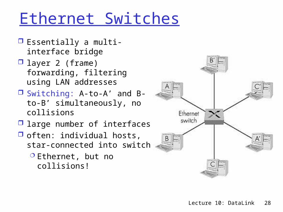
Ethernet Switches Essentially a multi-interface
bridge layer 2 (frame) forwarding,
filtering using LAN addresses Switching: A-to-A’ and B-to-
B’ simultaneously, no collisions
large number of interfaces often: individual hosts, star-
connected into switch Ethernet, but no
collisions!

Lecture 10: DataLink 29
Ethernet Switches
cut-through switching: frame forwarded from input to output port without awaiting for assembly of entire frameslight reduction in latency
combinations of shared/dedicated, 10/100/1000 Mbps interfaces

Lecture 10: DataLink 30
Typical Organization LAN(without backup switch… add one!)
Dedicated
Shared

Lecture 10: DataLink 31
Summary comparison
hubs bridges routers switches
traffi cisolation
no yes yes yes
plug & play yes yes no yes
optimalrouting
no no yes no
cutthrough
yes no no yes

Lecture 10: DataLink 32
Outline
Ethernet Hubs, bridges, switches, etc… A bit about:
wireless (IEEE 802.11 LANs) PPP ATM Frame Relay

Lecture 10: DataLink 33
Wireless network characteristicsMultiple wireless senders and receivers create
additional problems (beyond multiple access):
AB
C
Hidden terminal problem B, A hear each other B, C hear each other A, C can not hear each
othermeans A, C unaware of their
interference at B
A B C
A’s signalstrength
space
C’s signalstrength
Signal fading: B, A hear each other B, C hear each other A, C can not hear each other interfering at B Reality is worse than figure!

Lecture 10: DataLink 34
IEEE 802.11: multiple access Like Ethernet, uses CSMA:
random access carrier sense: don’t collide with ongoing transmission
Unlike Ethernet: Ack, no Collision Detection no collision detection – transmit all frames to completion ACK: to detect loss without collision detection
Why no collision detection? difficult to receive (sense collisions) when transmitting due
to weak received signals (fading) can’t sense all collisions in any case: hidden terminal,
fading And… loss may be due to (higher) error rate of wireless
Goal: avoid collisions: CSMA/C(ollision)A(voidance)

Lecture 10: DataLink 35
IEEE 802.11 MAC Protocol: CSMA/CA[simplified]
802.11 sender1 if sense channel idle then
- transmit entire frame (no CD)2 if sense channel busy then
- start random backoff timer- timer counts down while channel idle- transmit when timer expires- if no ACK within DIFS, increase
random backoff interval, repeat 2- DIFS>SIFS+2tprop
802.11 receiverif frame received OK then return ACK else ignore (no NACK!)SIFS: max time till Ack sent (SIFS=Short
Inter-Frame Space)
sender receiver
data
ACK
SIFS(e.g.10s)

Lecture 10: DataLink 36
IEEE 802.11 MAC Protocol: CSMA/CA
802.11 sender (when trying to send)1 if sense channel idle for DIFS then
- transmit entire frame (no CD)
[DIFS>SIFS+2Tprop for priority to ACK]
2 if sense channel busy then
- start random backoff timer
- timer counts down while channel idle
- transmit when timer expires
- if no ACK, increase random backoff interval, repeat 2
802.11 receiverif frame received OK
- return ACK
sender receiver
DIFS
data
ACK
SIFS(e.g.10s)

Lecture 10: DataLink 37
Ack
Data
Next MPDU
Src
Dest
Other
Contention Window
Defer Access Backoff after Defer
DIFS
SIFS
DIFS
Acknowledgment should arrive within SIFS Senders wait for DIFS no-carrier time, then
exponential backoff delay [slot=Tprop]
802.11 MAC OperationData Frames and their ACK

Lecture 10: DataLink 38
Problems with 802.11 MAC as above Technical problems:
`code` not precise, esp. re backoff, count-down Missing elements…
Spec also allows PCF (Point Coordination Function): polling to coordinate senders to ensure QoS
SIFS < PIFS < DIFS (priorities!) Can’t detect collision while sending…
Wasteful – esp. for long packets Idea for long packets: reserve channel to avoid
collisions – RTS/CTS [optional] mechanism…

Lecture 10: DataLink 39
RTS/CTS [optional in 802.11 MAC] Sender sends small request-to-send (RTS) to AP
RTSs may collide with each other (but are short) Include indication of length of packet
transmission Receiver broadcasts clear-to-send CTS in response
to RTS CTS heard by all nodes
sender transmits data frame other stations defer transmissions for time
specified in CTS
Avoid data frame collisions completely using small reservation packets!

Lecture 10: DataLink 40
Collision Avoidance: RTS-CTS exchange
APA B
time
RTS(A)RTS(B)
RTS(A)
CTS(A) CTS(A)
DATA (A)
ACK(A) ACK(A)
reservation collision
defer

Lecture 10: DataLink 41
Data Link Layer: Summary
principles behind data link layer services: error detection, correction sharing a broadcast channel: multiple access link layer addressing, ARP
link layer technologies: Ethernet, hubs, bridges, switches, IEEE 802.11 LANs, PPP, ATM, Frame Relay
End of introduction to networking… More: advanced networking & security
courses