Embed Size (px)
Citation preview

2/15/2016 1 1Lecture #12 – Fall 2015 1D. Mohr
151-0735: Dynamic behavior of materials and structures
by Dirk Mohr
ETH Zurich, Department of Mechanical and Process Engineering,
Chair of Computational Modeling of Materials in Manufacturing
Lecture #12:
• Elasticity and failure of fiber-reinforced composites
© 2015

2/15/2016 2 2Lecture #12 – Fall 2015 2D. Mohr
151-0735: Dynamic behavior of materials and structures
Intelligent Lightweight Engineering

2/15/2016 3 3Lecture #12 – Fall 2015 3D. Mohr
151-0735: Dynamic behavior of materials and structures
Intelligent Lightweight Engineering

2/15/2016 4 4Lecture #12 – Fall 2015 4D. Mohr
151-0735: Dynamic behavior of materials and structures
Elasticity of Fiber-reinforced laminae and laminates (cont.)

2/15/2016 5 5Lecture #12 – Fall 2015 5D. Mohr
151-0735: Dynamic behavior of materials and structures
DefinitionsDenote the three orthotropy direction by i, j, k. Then consider a uniaxial tensionexperiment along the orthotropy direction xi.
ii1
jj1
iiii
Plus thickness strain measurement
ii
iiiE
ii
jj
ij
kkt
t 1
0
We can define (& determine):
• Young’s modulus
• Poisson’s ratios
ii
kkik

2/15/2016 6 6Lecture #12 – Fall 2015 6D. Mohr
151-0735: Dynamic behavior of materials and structures
Plane stress law for an orthotropic material (2D)
For notational convenience, the elastic stress-strain relationship for anorthotropic material is also written as
1221
2
21
2
21
2
1
2
212
2
222
1/1
E
EE
E
EE
EQ
with
12
22
11
66
2212
1211
12
22
11
00
0
0
Q
1221
1
21
2
21
1
1
2
212
2111
1/1
E
EE
E
EE
EEQ
1221
121
1
2
212
212112
1
E
EE
EEQ
1266 2GQ

2/15/2016 7 7Lecture #12 – Fall 2015 7D. Mohr
151-0735: Dynamic behavior of materials and structures
Isotropy check
2221
E
Q
2111
E
Q
2121
EQ
2661
)1(
E
Q
1122 QQ
11
12
Q
Q
121111
11
1266 1 QQQ
Q
66
2212
1211
00
0
0
Q
Q1122 QQ
121166 QQQ defines an isotropic material if

2/15/2016 8 8Lecture #12 – Fall 2015 8D. Mohr
151-0735: Dynamic behavior of materials and structures
Constitutive equation for lamina As the same transformations are valid for the strain vector, the relationshipamong the stress and strain components in the (ex, ey)-frame is then given by
xy
yy
xx
xy
yy
xx
xy
yy
xx
Q
QQQ
Q
66
2622
161211
66
2212
1211
1
ˆ
ˆˆ
ˆˆˆ
00
0
0
TT
22
4
6612
22
11
4
11 )(2ˆ QsQQscQcQ
Upon evaluation, we find the components
12
44
662211
22
12 )()2(ˆ QcsQQQscQ
)(2)(2ˆ662212
3
661211
3
16 QQQcsQQQscQ
22
4
6612
22
11
4
22 )(2ˆ QcQQscQsQ
)(2)(2ˆ662212
3
661211
3
26 QQQscQQQcsQ
66
44
66122211
22
66 )()2(2ˆ QscQQQQscQ
Note that the mathematical definition of the shear strain is applied. Many textbooks and FE programs adopt theengineering definition. In that case, the third column of the stiffness matrix Q needs to be multiplied with 0.5.
sym
]cos[c
]sin[s

2/15/2016 9 9Lecture #12 – Fall 2015 9D. Mohr
151-0735: Dynamic behavior of materials and structures
Membrane response of laminates
Let denote the stiffness matrix of the i-th lamina in the (ex, ey)-coordinateframe, the stress-strain relationship for the laminate is then given by the rule ofmixtures:
xy
yy
xx
tot
xy
yy
xx
Q̂
iQ̂
with
N
i
i
tot
itot
t
t
1
ˆˆ QQ
ttot①②③④⑤⑥
Thickness fraction

2/15/2016 10 10Lecture #12 – Fall 2015 10D. Mohr
151-0735: Dynamic behavior of materials and structures
Fiber volume fraction
The fiber volume fraction Vf is a first basic characteristic of the two-phasecomposite microstructure.
volumetotal
fiberofvolumeV f
91.032
)max(
fV
The hexagonally closed-packed array provides a theoretical upper limit for thefiber volume fraction.

2/15/2016 11 11Lecture #12 – Fall 2015 11D. Mohr
151-0735: Dynamic behavior of materials and structures
Material directions
A unidirectional composite laminae features two in-plane directions and oneout-of-plane direction. The latter is also referred to as thickness direction. Thelongitudinal direction coincides with the fiber direction, while in-plane directionthat is perpendicular to the fibers is called the transverse direction.
Thickness direction
Transversedirection
Longitudinaldirection

2/15/2016 12 12Lecture #12 – Fall 2015 12D. Mohr
151-0735: Dynamic behavior of materials and structures
Longitudinal modulus
The longitudinal modulus corresponds to the slope of the stress-strain curvewhen the lamina is subject to uniaxial tension along the longitudinal direction.
1111 )1( mfff AEVAEVAE
mff EVEE )1(1
)1( 1L
1 1
MATRIX
FIBER

2/15/2016 13 13Lecture #12 – Fall 2015 13D. Mohr
151-0735: Dynamic behavior of materials and structures
Poisson’s ratio
Using a simple layer model of the fiber reinforced composite, the Poisson’s ratiocan be estimated.
fffm WVVWW 11112 )1(
)1( 112W
)1( 1L
)1()1( 1mf WV
)1( 1 ffWV
fffm VV )1(12
1 1
MATRIX
FIBER

2/15/2016 14 14Lecture #12 – Fall 2015 14D. Mohr
151-0735: Dynamic behavior of materials and structures
In-plane shear modulus
Using a simple layer model of the fiber reinforced composite, the in-plane shearmodulus can be estimated.
WVG
WVG
WG
f
m
f
f
)1(1212
12
12
WVG
f
f
12WV
Gf
m
)1(12
WG12
12
12
m
f
f
fG
VG
VG
1)1(
11
12
MATRIX
FIBER

2/15/2016 15 15Lecture #12 – Fall 2015 15D. Mohr
151-0735: Dynamic behavior of materials and structures
Transverse Modulus
)1( 2W
2
Using a simple layer model of the fiber reinforced composite, the transversemodulus can be estimated.
m
f
f
fE
WVE
WVE
W 22
2
2 )1(
m
f
f
fE
VE
VE
1)1(
11
2
2
MATRIX
FIBER

2/15/2016 16 16Lecture #12 – Fall 2015 16D. Mohr
151-0735: Dynamic behavior of materials and structures
Elastic lamina property estimates: summary
• Longitudinal modulus
mff EVEE )1(1
• Transverse modulus
m
f
f
fE
VE
VE
1)1(
11
2
• In-plane shear modulus
m
f
f
fG
VG
VG
1)1(
11
12
• In-plane Poisson’s ratios
fffm VV )1(12
1
21221
E
E and
)1(2 f
f
f
EG
)1(2 m
mm
EG
with

2/15/2016 17 17Lecture #12 – Fall 2015 17D. Mohr
151-0735: Dynamic behavior of materials and structures
Elastic lamina property estimates: example
INPUT:Phase properties
GPaE f 75
GPaEm 5
22.0f
35.0m
7.0fV
OUTPUT:Lamina properties
GPaE 541
GPaE 4.142
26.012
07.021
Vf Ef Em nue_f nue_m Gf Gm E1 E2 nue_12 nue_21 G12
[MPa] [MPa] [-] [-] [MPa] [Mpa] [MPa] [MPa] [-] [-] [MPa]
0.7 75,000 5,000 0.22 0.35 30,738 1,852 54,000 14,423 0.26 0.07 5,412
GPaG 4.512
Evaluation of the above formulas for an E-glass composite with afiber volume fraction of 70% yields:

2/15/2016 18 18Lecture #12 – Fall 2015 18D. Mohr
151-0735: Dynamic behavior of materials and structures
Elastic lamina property estimates: example
OUTPUT:Lamina properties
GPaE 541
GPaE 4.142
26.012
07.021
GPaG 4.512
As an alternative to using the material constants {E1,E2,G12,12},the elastic lamina properties may be described through {Q11, Q12,Q22, Q66}.
12
22
11
66
2212
1211
12
22
11
00
0
0
Q
GPaQ 5511 GPaQ 1522
GPaQ 8.312 GPaQ 1166
E1 E2 nue_12 nue_21 G12 Q11 Q22 Q12 Q66
[MPa] [MPa] [-] [-] [MPa] [MPa] [MPa] [MPa] [MPa]
54,000 14,423 0.26 0.07 5,412 54,985 14,686 3,804 10,824

2/15/2016 19 19Lecture #12 – Fall 2015 19D. Mohr
151-0735: Dynamic behavior of materials and structures
Elastic lamina property estimates: example
12
22
11
66
22
1211
12
22
11
0
0
Q
Q
GPaQ 5511 GPaQ 1522
GPaQ 8.312 GPaQ 1166
GPaQ 37ˆ11 GPaQ 17ˆ
22
GPaQ 11ˆ12 GPaQ 26ˆ
66
xy
yy
xx
xy
yy
xx
Q
QQQ
66
2622
161211
ˆ
ˆˆ
ˆˆˆ
Q11 Q22 Q12 Q66 alpha QH11 QH12 QH16 QH22 QH26 QH66
[MPa] [MPa] [MPa] [MPa] [deg] [MPa] [MPa] [MPa] [MPa] [MPa] [MPa]
54,985 14,686 3,804 10,824 30 37,332 11,382 26,200 17,183 8,700 25,980
GPaQ 26ˆ16 GPaQ 9ˆ
26

2/15/2016 20 20Lecture #12 – Fall 2015 20D. Mohr
151-0735: Dynamic behavior of materials and structures
“Black aluminum”
The properties of a carbon fiber composite laminate can beadjusted such that it provides similar stiffness properties asaluminum. Starting point is a [0°, 60°, -60°] lay-up which featuresisotropic in-plane properties (hexagonal symmetry).
GPaE f 300 0
60
60

2/15/2016 21 21Lecture #12 – Fall 2015 21D. Mohr
151-0735: Dynamic behavior of materials and structures
“Black aluminum”
The calculation shows that for a fiber volume fraction of Vf=0.62of carbon fibers of fiber modulus Ef=300GPa, an isotropic [0,60,-60] laminate exhibits the same in-plane modulus of 70 GPa asaluminum.
Vf Ef Em nue_f nue_m Gf Gm E1 E2 nue_12 nue_21 G12 Q11 Q22 Q12 Q66 alpha QH11 QH22 QH12 QH66 QH16 QH26
[MPa] [MPa] [-] [-] [MPa] [Mpa] [MPa] [MPa] [-] [-] [MPa] [MPa] [MPa] [MPa] [MPa] [deg] [MPa] [MPa] [MPa] [MPa] [MPa] [MPa]
0.62 300,000 5,000 0.22 0.35 122,951 1,852 187,155 12,729 0.27 0.02 4,726 188,085 12,792 3,450 9,452 0 188,085 12,792 3,450 9,452 0 0
0.62 300,000 5,000 0.22 0.35 122,951 1,852 187,155 12,729 0.27 0.02 4,726 188,085 12,792 3,450 9,452 -60 23,789 111,436 36,276 75,104 -38,000 -113,808
0.62 300,000 5,000 0.22 0.35 122,951 1,852 187,155 12,729 0.27 0.02 4,726 188,085 12,792 3,450 9,452 60 23,789 111,436 36,276 75,104 38,000 113,808
LAMINATE: 78,555 78,555 25,334 53,220 0 0
1 70,000 70,000 0.33 0.33 26,316 26,316 70,000 70,000 0.33 0.33 26,316 78,555 78,555 25,923 52,632 0 78,555 78,555 25,923 52,632 0 0
ALUMINUM 78,555 78,555 25,923 52,632 0 0
The mass density of this laminate would be about 1.7 g/cm3 andthus about 40% lighter than aluminum.
The weight savings can be increased to about 50% through the use of high stiffness carbon fiberswith a modulus of 800GPa. However, in engineering practice, even higher weight savings areachieved through the use of anisotropic laminates.

2/15/2016 22 22Lecture #12 – Fall 2015 22D. Mohr
151-0735: Dynamic behavior of materials and structures
Lamina Failure

2/15/2016 23 23Lecture #12 – Fall 2015 23D. Mohr
151-0735: Dynamic behavior of materials and structures
Selected Failure Mechanisms
Source: Stefan Hartmann, DYNAmore GmbH, Composite Berechnung in LS-DYNA, Stuttgart (2013)

2/15/2016 24 24Lecture #12 – Fall 2015 24D. Mohr
151-0735: Dynamic behavior of materials and structures
Uniaxial tension of unidirectional carbon fiber composite
Source: https://www.youtube.com/watch?feature=player_detailpage&v=NMiZQxBKu-E

2/15/2016 25 25Lecture #12 – Fall 2015 25D. Mohr
151-0735: Dynamic behavior of materials and structures
Uniaxial tension of Carbon fiber Fabric Composite
Source: https://www.youtube.com/watch?feature=player_detailpage&v=aH9vcV7jzG0

2/15/2016 26 26Lecture #12 – Fall 2015 26D. Mohr
151-0735: Dynamic behavior of materials and structures
Intra-laminar failure mechanisms
A laminate may fail due to delamination of the constituentlaminae, which is an inter-laminar failure mechanism. Inter-laminar failure is often preceded by intra-laminar failure whichincludes four basic failure mechanisms:
(1) Fiber tension failure
(2) Matrix failure under combined compression and shear
(3) Matrix failure under combined tension and shear
(4) Fiber compression failure (kinking)

2/15/2016 27 27Lecture #12 – Fall 2015 27D. Mohr
151-0735: Dynamic behavior of materials and structures
(1) Fiber tension failure
11
11
In a first approximation, fiber tension failure is predicted using a maximum stress failurecriterion. In other words, the stress along the fiber direction of a lamina may not exceedthe tensile strength Xt,
tX11
As an alternative, a maximum strain criterion may be used:
t 11

2/15/2016 28 28Lecture #12 – Fall 2015 28D. Mohr
151-0735: Dynamic behavior of materials and structures
(2) Matrix compression-shear failure
2
22 )(cos)( nσnn
sin
cos
0
n
000
0
0
2212
1211
σ
cos
sin
0
Tt
0
0
1
Lt
In a plane stress model, the stresses acting on plane which is inclined at an angle withrespect to the thickness-direction are
cos)( 12 LL tσn
1
2
3
Source: Pinho et al. (Composites A, 2006)
22
22
12
12

2/15/2016 29 29Lecture #12 – Fall 2015 29D. Mohr
151-0735: Dynamic behavior of materials and structures
(2) Matrix compression-shear failure
1
22
nLL
L
nTT
T
SS
The Puck’s semi-empirical matrix failure criterion for transverse compression reads
Source: Pinho et al. (Composites A, 2006)
with the longitudinal and transverse shear strengths ST and SL, and the frictionparameters T and L. The orientation of the critical plane is found defined by the angle for which the criterion is met first.
0nif
1
2
322
22
12
12

2/15/2016 30 30Lecture #12 – Fall 2015 30D. Mohr
151-0735: Dynamic behavior of materials and structures
(2) Matrix compression-shear failure
The four parameters of Puck model may be determined based on
Reference: Pinho et al. (Composites A, 2006)
• The strength Yc, and failure plane orientation 0 measured in a transversecompression test
• The in-plane shear strength SL
using the relationships
]2tan[
1
0 T
]2tan[2 0c
T
YS T
T
LL
S
S
1
2
322
22
12
12
(estimate after Puck)

2/15/2016 31 31Lecture #12 – Fall 2015 31D. Mohr
151-0735: Dynamic behavior of materials and structures
(3) Matrix tension-shear failure
1
2
12
2
22
LT SY
022 if
Experimental data suggests a quadratic interaction of thetransverse stress and the in-plane shear stress,
1
222
L
L
T
T
T
n
SSY
0nif
22
22
12
12
A modified version providing also the fracture plane for tension-dominatedmatrix failure has been advocated by Pinho et al. (2006),

2/15/2016 32 32Lecture #12 – Fall 2015 32D. Mohr
151-0735: Dynamic behavior of materials and structures
Experimental validation of matrix failure model(unidirectional E-glass/LY556 lamina)
Pinho et al. (2006)
22
12
Yc [MPa] Yt [MPa] SL [MPa] 0 [deg]
130.3 37.5 66.5 53
Model parameters:
Results from compression/tension-torsionexperiments by Hutter et al. (1974) oncircumferentially wound tubes (60mm diam.,2mm thick)

2/15/2016 33 33Lecture #12 – Fall 2015 33D. Mohr
151-0735: Dynamic behavior of materials and structures
(4) Fiber compression failure
Under compression-dominated loading along the fiber direction,unidirectional laminae fail through fiber kinking.
Source: Pinho et al. (2006)
Due to initial fiber misalignment, a portion of the axial load isredistributed onto the matrix material. Fiber compression failureis thus expected to occur when the matrix material in regions ofmisalignment fails.

2/15/2016 34 34Lecture #12 – Fall 2015 34D. Mohr
151-0735: Dynamic behavior of materials and structures
(4) Fiber compression failure
To illustrate the concept, we assume that the matrix fails when the longitudinalshear stress reaches a critical value SL (Argon’s model). Assuming that themacroscopic stress along the fiber axis 11 is redistributed from the fiber to thematrix due to a small fiber misalignment of angle qi, we have the longitudinalshear stress
1111
iq
nt
iii
i
i
i
iqqq
q
q
q
q 1111
11cossin
sin
cos
cos
sin
00
0)(
tσn

2/15/2016 35 35Lecture #12 – Fall 2015 35D. Mohr
151-0735: Dynamic behavior of materials and structures
(4) Fiber compression failure
1111
iq
nt
And hence, according to this simple model, the relationship between thecompression failure stress Xc and the longitudinal shear failure stress SL:
icL XS q
Following the same concept, more advanced fiber kinking failure models (e.g.Pinho et al., 2006) can be developed, in particular through the use of moreadvanced matrix failure models such as the one present before.

2/15/2016 36 36Lecture #12 – Fall 2015 36D. Mohr
151-0735: Dynamic behavior of materials and structures
Hashin’s damage initiation model
1
2
12
2
11
Lt SX
Another intra-laminar failure model is due to Hashin (1980). Inclose analogy with the above, it provides separate criteria for thefailure mechanisms:
• Fiber tension
1
2
11
cX
• Fiber compression
1
2
12
2
22
Lt SY
• Matrix tension
1122
2
1222
22
22
LcT
c
T SYS
Y
S
• Matrix compression

2/15/2016 37 37Lecture #12 – Fall 2015 37D. Mohr
151-0735: Dynamic behavior of materials and structures
Single function failure models
Instead of using different criteria accounting for different intra-laminar failuremodes, an attempt was made to provide a single analytical form to predict thefailure of laminae. One of the first models of this type is the Tsai-Hill failurecriterion. In close mathematical analogy with the anisotropic Hill’48 yieldfunction, the Tsai-Hill criterion reads
12
12221112
2
222
2
111 SFFFF
The main shortcoming of the Tsai-Hill criterion is its inability to differentiatebetween compression and tension, i.e. it predicts the same strength forcompression and tension along the fiber direction.
This issue has been addressed by the Tsai-Wu failure criterion
2/15/2016 38 38Lecture #12 – Fall 2015 38D. Mohr
151-0735: Dynamic behavior of materials and structures
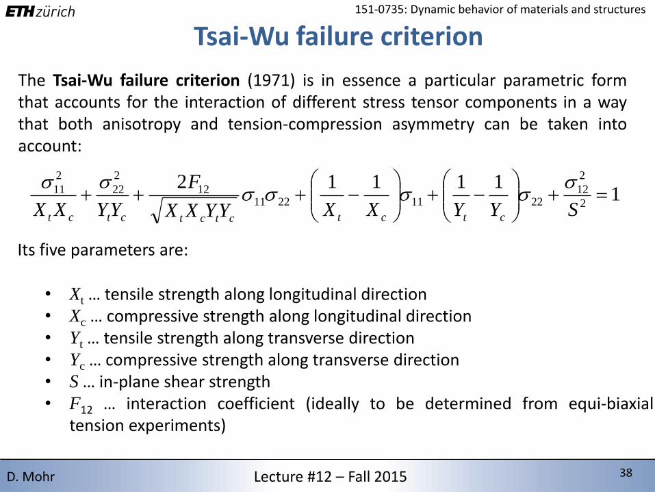
Tsai-Wu failure criterion
The Tsai-Wu failure criterion (1971) is in essence a particular parametric formthat accounts for the interaction of different stress tensor components in a waythat both anisotropy and tension-compression asymmetry can be taken intoaccount:
111112
2
2
1222112211
12
2
22
2
11
SYYXXYYXX
F
YYXX ctctctctctct
Its five parameters are:
• Xt … tensile strength along longitudinal direction• Xc … compressive strength along longitudinal direction• Yt … tensile strength along transverse direction• Yc … compressive strength along transverse direction• S … in-plane shear strength• F12 … interaction coefficient (ideally to be determined from equi-biaxial
tension experiments)

2/15/2016 39 39Lecture #12 – Fall 2015 39D. Mohr
151-0735: Dynamic behavior of materials and structures
Modeling Choices & Limitations
Source: Stefan Hartmann, DYNAmore GmbH, Composite Berechnung in LS-DYNA, Stuttgart (2013)

2/15/2016 40 40Lecture #12 – Fall 2015 40D. Mohr
151-0735: Dynamic behavior of materials and structures
Next: Damage modeling
Source: R. Talreja, C. Veer Singh, Damage and Failure of Composite Materials

2/15/2016 41 41Lecture #12 – Fall 2015 41D. Mohr
151-0735: Dynamic behavior of materials and structures
Reading Materials for Lecture #12
• E.J. Barbero (2011), Introduction to Composite Materials Design
• R. Talreja, C. Veer Singh (2012), Damage and Failure of Composite Materials
• S.T. Pinho, L. Iannucci, P. Robinson (2006), Physically-based failure models and criteria for laminated fibre-reinforced composites with emphasis on fibrekinking: Part I: Development, Composites Part A 37, 63-73.
• S.T. Pinho, L. Iannucci, P. Robinson (2006), Physically-based failure models and criteria for laminated fibre-reinforced composites with emphasis on fibrekinking: Part II: FE Implementation, Composites Part A 37, 766-777.


![92 / 0735-54-2510 · 2020. 3. 11. · 13 El (El) (8:30 (JYfiÎfiffiìËùíj 2,800 1,800 IT] 830 0735-54-2510 0735-54-1540 info ev@ugui-vc.jp (tBñ)](https://img.pdfslide.net/doc/110x75/60c46723ecb8834234005d27/92-0735-54-2510-2020-3-11-13-el-el-830-jyfififfij-2800-1800.jpg)