Embed Size (px)
Citation preview
EE 595
Part IIDesign Units in VHDL
EE 595 EDA / ASIC Design Lab
Design UnitsThere are five type of design units in VHDL:
EntitiesArchitecturesPackagesPackage BodiesConfigurations
Entities and architectures are the only two design units that you must have in any VHDL design descriptions.Packages and configuration are optional.
EE 595 EDA / ASIC Design Lab
Design Units (cont’d)Primary Design Units
1. Entity Declaration2. Package Declaration3. Configuration Declaration
Secondary Design Units
1. Architecture Body2. Package Body.
EE 595 EDA / ASIC Design Lab
VHDL Design UnitsEntityPrimary unit of VHDL designs. It is the design’s interface to the outside world. Even the top most level of a hierarchy design must have an entity. Entities define I/O ports and timing information (generics) but can also used to do complete setup/hold checking.
ArchitectureDescribes behavior and/or structure of a specific entity. One entity can have many architectures associated with it but only one can be used with a given entity during simulation. Architectures are always compiled after compiling the entities they reference.
EE 595 EDA / ASIC Design Lab
VHDL Design Units (cont’d)ConfigurationUsed to bind entities to architectures for simulation. Required for simulating structural designs (ones with underlying components - netlists) but is not required for purely behavioral designs. Configurations are generally the final design unit to be compiled.
Package“toolbox” (similar to a C “include file”) that can contain the declaration for common data types, constants, subprograms, and component declarations. Packages must be compiled first, before anything that depends on them (there are both standard packages and user defined packages)
EE 595 EDA / ASIC Design Lab
VHDL Design Units (cont’d)PACKAGE BODYThe code for the bodies of the subprograms declared in the PACKAGE. Has the same name as Package so there can be only be one Package Body for each Package. Can be compiled at any time after Package; other design unit’s dependencies are on the Package, not the Package body.
EE 595 EDA / ASIC Design Lab
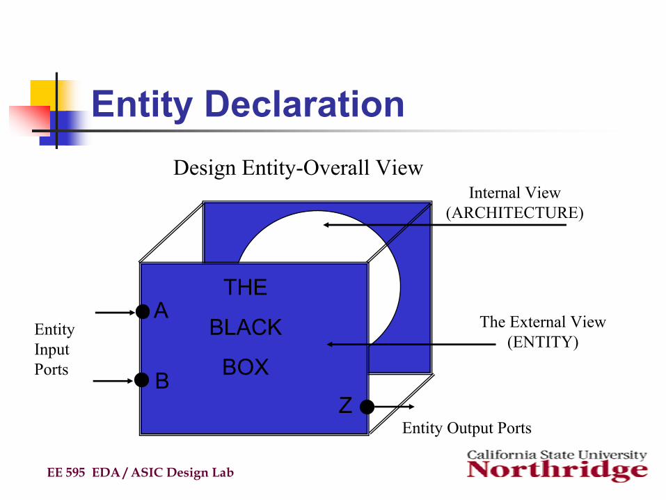
Entity Declaration
EE 595 EDA / ASIC Design Lab
THE
BLACK
BOX
A
BZ
Entity Output Ports
Design Entity-Overall View
EntityInputPorts
The External View(ENTITY)
Internal View(ARCHITECTURE)
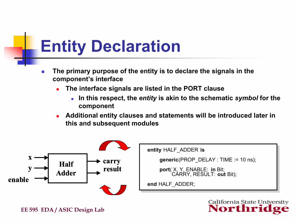
Entity DeclarationThe primary purpose of the entity is to declare the signals in the component’s interface
The interface signals are listed in the PORT clauseIn this respect, the entity is akin to the schematic symbol for the component
Additional entity clauses and statements will be introduced later in this and subsequent modules
EE 595 EDA / ASIC Design Lab
entity HALF_ADDER is
generic(PROP_DELAY : TIME := 10 ns);
port( X, Y, ENABLE: in Bit;CARRY, RESULT: out Bit);
end HALF_ADDER;
xy
enable
carryresultHalf
Adder
xy
enable
carryresultHalf
Adder

Entity Declaration (cont’d)PORT clause declares the interface signals of the object to the outside worldThree parts of the PORT clause
NameModeData type
Example PORT clause:
Note port signals (i.e. ‘ports’) of the same mode and type or subtype may be declared on the same line
EE 595 EDA / ASIC Design Lab
port (SIGNAL_NAME : MODE DATA_TYPE);port (SIGNAL_NAME : MODE DATA_TYPE);
port ( INPUT : in Bit_Vector(3 DOWNTO 0);READY, OUTPUT : out Bit );
port ( INPUT : in Bit_Vector(3 DOWNTO 0);READY, OUTPUT : out Bit );
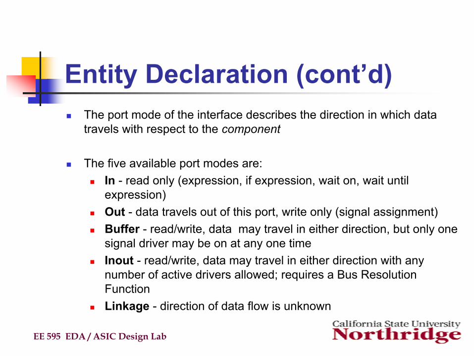
Entity Declaration (cont’d)The port mode of the interface describes the direction in which data travels with respect to the component
The five available port modes are: In - read only (expression, if expression, wait on, wait until expression)Out - data travels out of this port, write only (signal assignment)Buffer - read/write, data may travel in either direction, but only one signal driver may be on at any one timeInout - read/write, data may travel in either direction with any number of active drivers allowed; requires a Bus Resolution FunctionLinkage - direction of data flow is unknown
EE 595 EDA / ASIC Design Lab
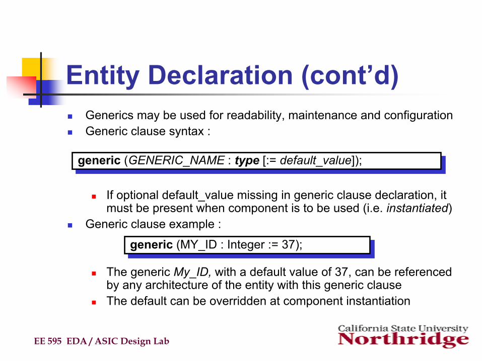
Entity Declaration (cont’d)Generics may be used for readability, maintenance and configurationGeneric clause syntax :
If optional default_value missing in generic clause declaration, it must be present when component is to be used (i.e. instantiated)
Generic clause example :
The generic My_ID, with a default value of 37, can be referenced by any architecture of the entity with this generic clauseThe default can be overridden at component instantiation
EE 595 EDA / ASIC Design Lab
generic (GENERIC_NAME : type [:= default_value]);generic (GENERIC_NAME : type [:= default_value]);
generic (MY_ID : Integer := 37);generic (MY_ID : Integer := 37);
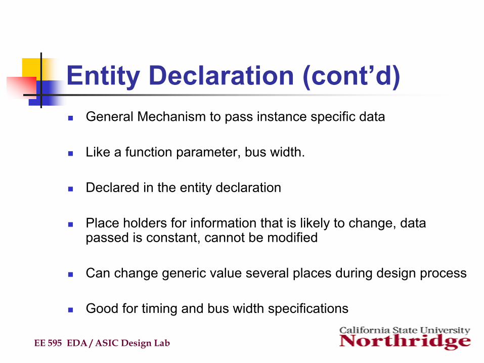
Entity Declaration (cont’d)General Mechanism to pass instance specific data
Like a function parameter, bus width.
Declared in the entity declaration
Place holders for information that is likely to change, data passed is constant, cannot be modified
Can change generic value several places during design process
Good for timing and bus width specifications
EE 595 EDA / ASIC Design Lab
Architecture
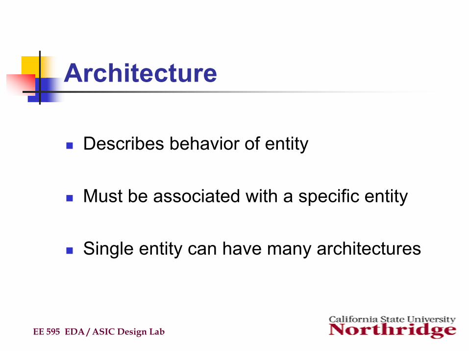
Describes behavior of entity
Must be associated with a specific entity
Single entity can have many architectures
EE 595 EDA / ASIC Design Lab
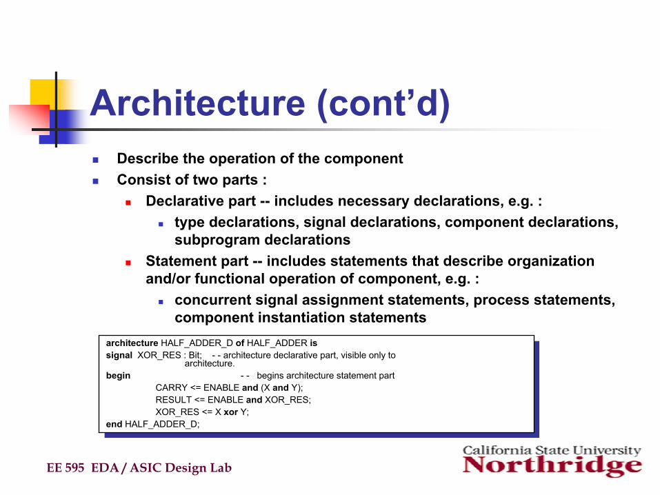
Architecture (cont’d)Describe the operation of the componentConsist of two parts :
Declarative part -- includes necessary declarations, e.g. : type declarations, signal declarations, component declarations, subprogram declarations
Statement part -- includes statements that describe organization and/or functional operation of component, e.g. :
concurrent signal assignment statements, process statements, component instantiation statements
EE 595 EDA / ASIC Design Lab
architecture HALF_ADDER_D of HALF_ADDER issignal XOR_RES : Bit; - - architecture declarative part, visible only to
architecture.begin - - begins architecture statement part
CARRY <= ENABLE and (X and Y);RESULT <= ENABLE and XOR_RES;XOR_RES <= X xor Y;
end HALF_ADDER_D;
architecture HALF_ADDER_D of HALF_ADDER issignal XOR_RES : Bit; - - architecture declarative part, visible only to
architecture.begin - - begins architecture statement part
CARRY <= ENABLE and (X and Y);RESULT <= ENABLE and XOR_RES;XOR_RES <= X xor Y;
end HALF_ADDER_D;
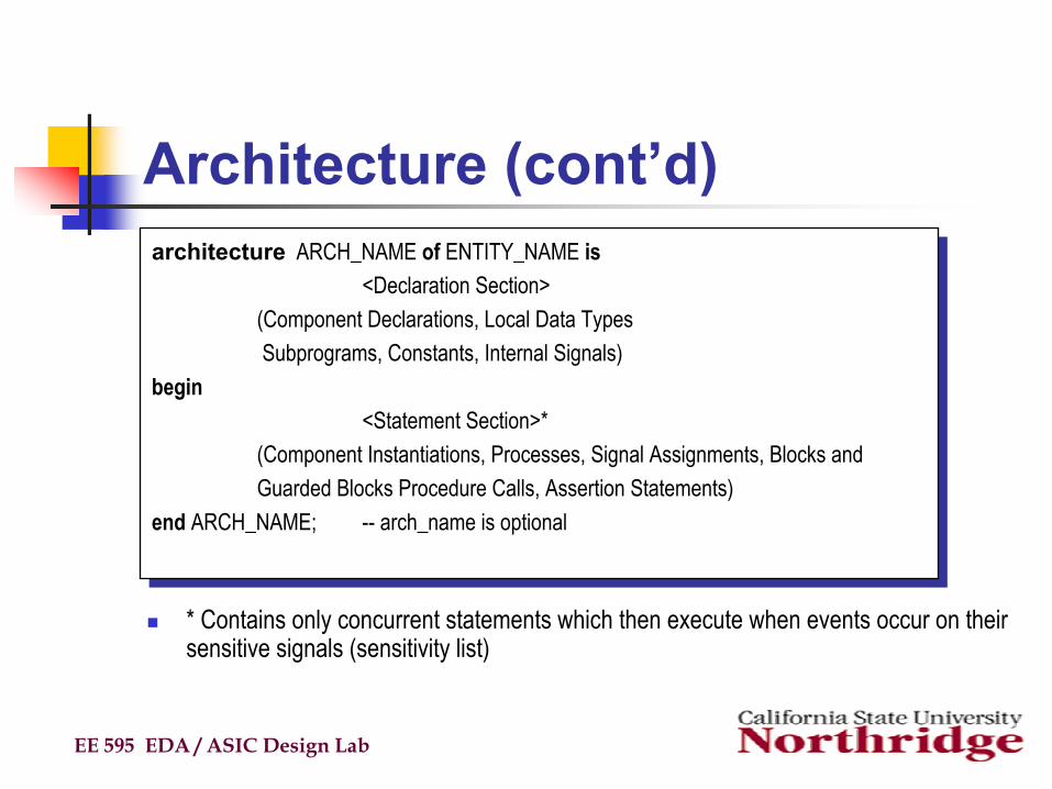
Architecture (cont’d)
* Contains only concurrent statements which then execute when events occur on their sensitive signals (sensitivity list)
EE 595 EDA / ASIC Design Lab
architecture ARCH_NAME of ENTITY_NAME is<Declaration Section>
(Component Declarations, Local Data TypesSubprograms, Constants, Internal Signals)
begin<Statement Section>*
(Component Instantiations, Processes, Signal Assignments, Blocks and Guarded Blocks Procedure Calls, Assertion Statements)
end ARCH_NAME; -- arch_name is optional
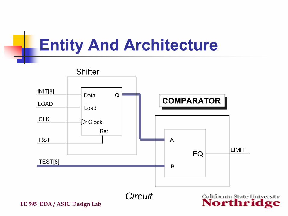
Entity And Architecture
EE 595 EDA / ASIC Design Lab
Data
Load
ClockRst
Q
A
B
EQ
INIT[8]
LOAD
CLK
RST
TEST[8]
LIMIT
Circuit
COMPARATORCOMPARATOR
Shifter
Design Example
EE 595 EDA / ASIC Design Lab
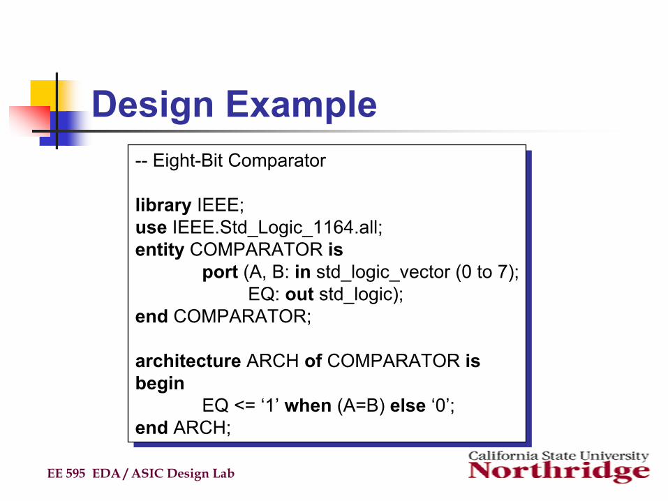
-- Eight-Bit Comparator
library IEEE;use IEEE.Std_Logic_1164.all;entity COMPARATOR is
port (A, B: in std_logic_vector (0 to 7);EQ: out std_logic);
end COMPARATOR;
architecture ARCH of COMPARATOR isbegin
EQ <= ‘1’ when (A=B) else ‘0’;end ARCH;
-- Eight-Bit Comparator
library IEEE;use IEEE.Std_Logic_1164.all;entity COMPARATOR is
port (A, B: in std_logic_vector (0 to 7);EQ: out std_logic);
end COMPARATOR;
architecture ARCH of COMPARATOR isbegin
EQ <= ‘1’ when (A=B) else ‘0’;end ARCH;
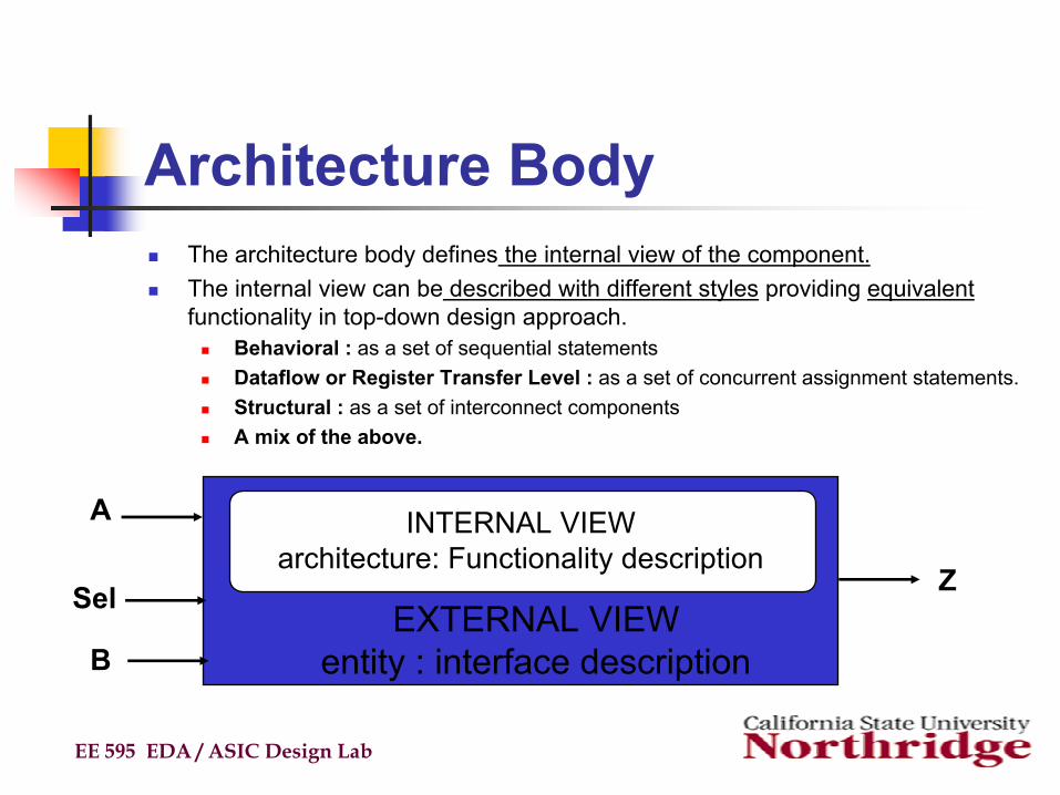
Architecture BodyThe architecture body defines the internal view of the component.The internal view can be described with different styles providing equivalentfunctionality in top-down design approach.
Behavioral : as a set of sequential statementsDataflow or Register Transfer Level : as a set of concurrent assignment statements.Structural : as a set of interconnect componentsA mix of the above.
EE 595 EDA / ASIC Design Lab
INTERNAL VIEWarchitecture: Functionality description
EXTERNAL VIEWentity : interface description
A
B
Sel Z
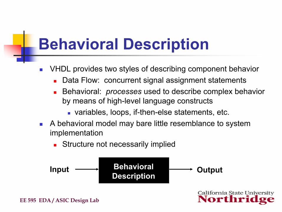
Behavioral DescriptionVHDL provides two styles of describing component behavior
Data Flow: concurrent signal assignment statementsBehavioral: processes used to describe complex behavior by means of high-level language constructs
variables, loops, if-then-else statements, etc.A behavioral model may bare little resemblance to system implementation
Structure not necessarily implied
EE 595 EDA / ASIC Design Lab
Input OutputBehavioral Description
Behavioral Description (cont’d)Behavior style of modeling specifies the behavior of an entity as a set of sequential statements which are executed in specified order.This set of statements are specified inside a process statement.These sequential statements inside process do not explicitly specify the structure of the entity but nearly specifies the functionality.A process as a whole is a concurrent statement that can appear within an architecture body.
EE 595 EDA / ASIC Design Lab
Concurrent StatementBasic granularity of concurrency is the process
Processes are executed concurrentlyConcurrent signal assignment statements are one-line processes
Mechanism for achieving concurrency :Processes communicate with each other via signalsSignal assignments require delay before new value is assumedSimulation time advances when all active processes completeEffect is concurrent processing
I.e. order in which processes are actually executed by simulator does not affect behavior
Concurrent VHDL statements include :Block, process, assert, signal assignment, procedure call, component instantiation
EE 595 EDA / ASIC Design Lab
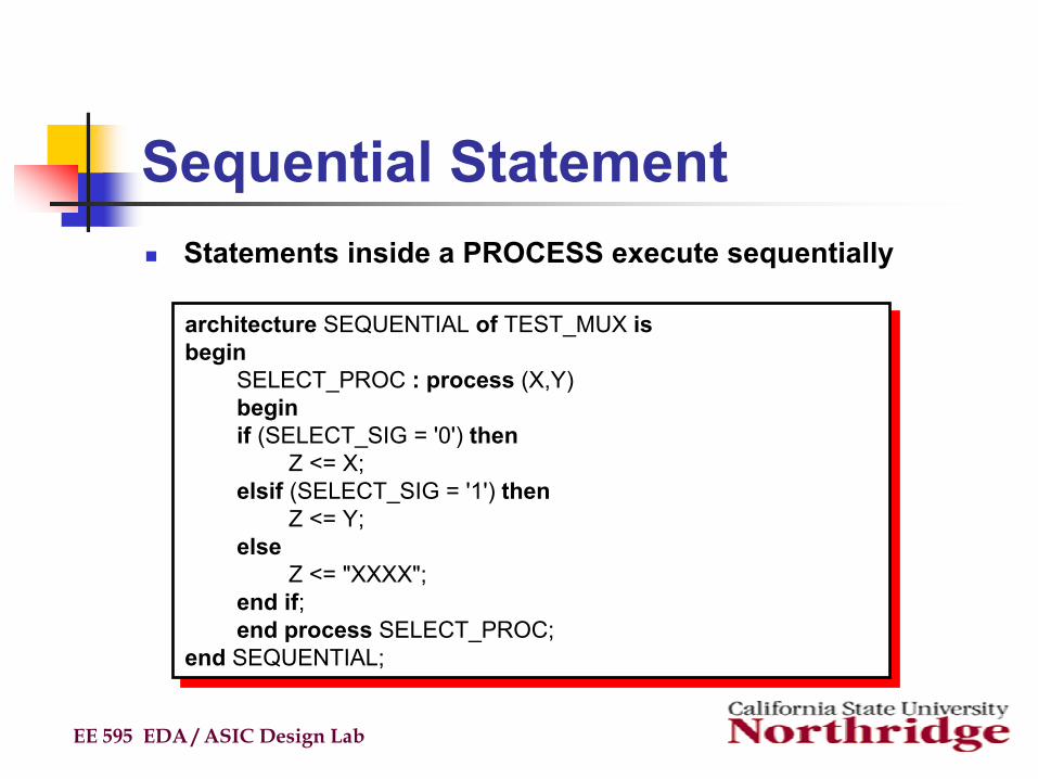
Sequential StatementStatements inside a PROCESS execute sequentially
EE 595 EDA / ASIC Design Lab
architecture SEQUENTIAL of TEST_MUX isbegin
SELECT_PROC : process (X,Y) beginif (SELECT_SIG = '0') then
Z <= X;elsif (SELECT_SIG = '1') then
Z <= Y;else
Z <= "XXXX";end if;end process SELECT_PROC;
end SEQUENTIAL;
architecture SEQUENTIAL of TEST_MUX isbegin
SELECT_PROC : process (X,Y) beginif (SELECT_SIG = '0') then
Z <= X;elsif (SELECT_SIG = '1') then
Z <= Y;else
Z <= "XXXX";end if;end process SELECT_PROC;
end SEQUENTIAL;
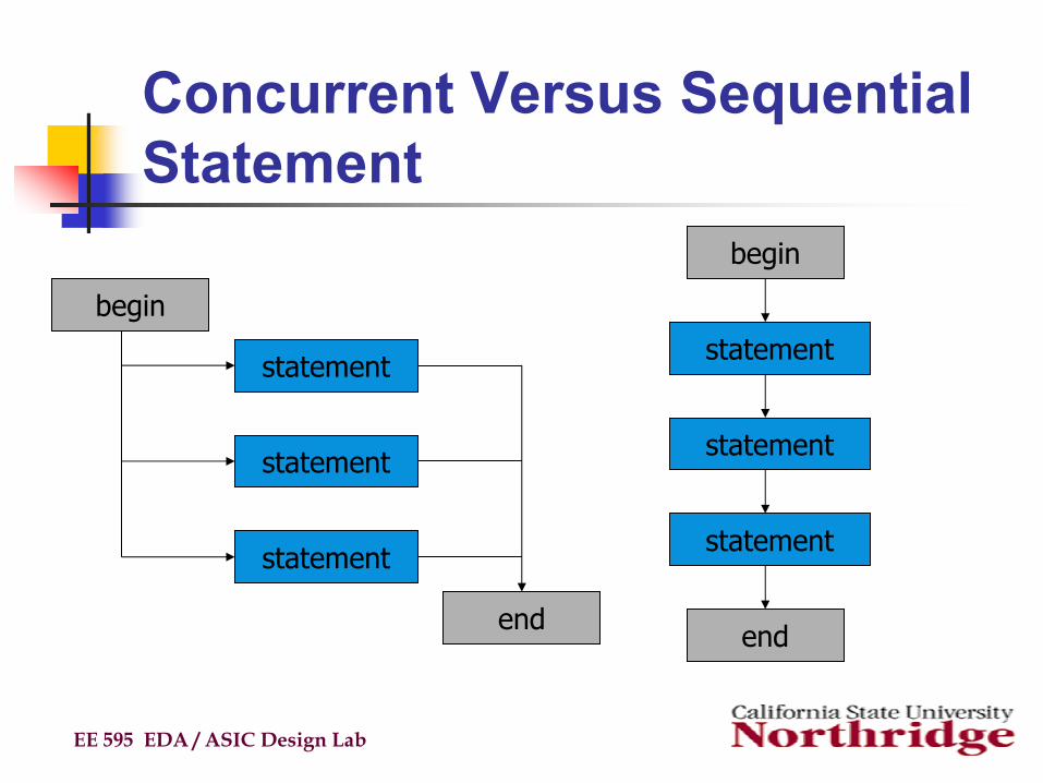
Concurrent Versus Sequential Statement
EE 595 EDA / ASIC Design Lab
statement
statement
statement
begin
end
statement
begin
statement
end
statement
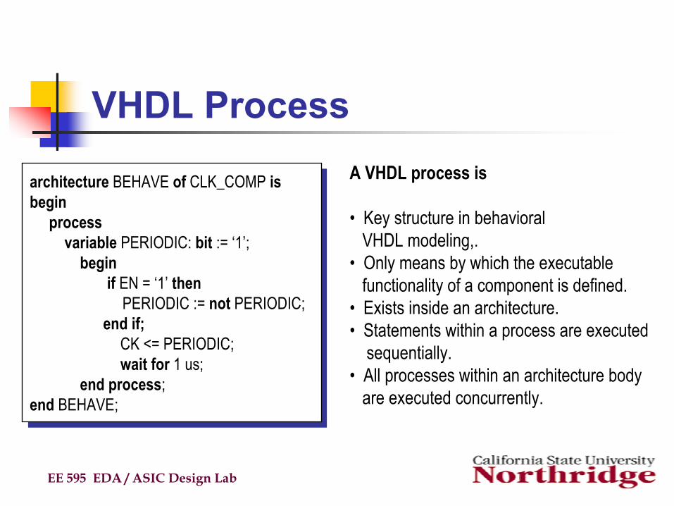
VHDL Process
EE 595 EDA / ASIC Design Lab
architecture BEHAVE of CLK_COMP isbegin
processvariable PERIODIC: bit := ‘1’;
beginif EN = ‘1’ then
PERIODIC := not PERIODIC;end if;
CK <= PERIODIC;wait for 1 us;
end process;end BEHAVE;
architecture BEHAVE of CLK_COMP isbegin
processvariable PERIODIC: bit := ‘1’;
beginif EN = ‘1’ then
PERIODIC := not PERIODIC;end if;
CK <= PERIODIC;wait for 1 us;
end process;end BEHAVE;
A VHDL process is
• Key structure in behavioral VHDL modeling,.
• Only means by which the executable functionality of a component is defined.
• Exists inside an architecture.• Statements within a process are executed
sequentially.• All processes within an architecture body
are executed concurrently.
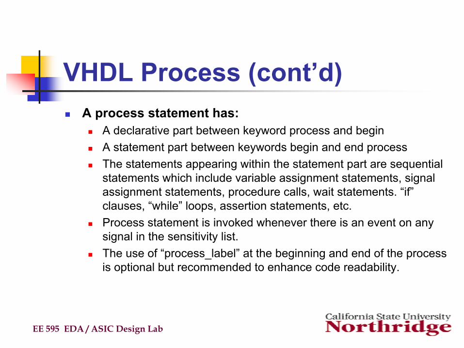
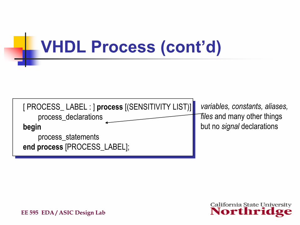
VHDL Process (cont’d)A process statement has:
A declarative part between keyword process and beginA statement part between keywords begin and end processThe statements appearing within the statement part are sequential statements which include variable assignment statements, signal assignment statements, procedure calls, wait statements. “if” clauses, “while” loops, assertion statements, etc. Process statement is invoked whenever there is an event on any signal in the sensitivity list.The use of “process_label” at the beginning and end of the process is optional but recommended to enhance code readability.
EE 595 EDA / ASIC Design Lab
VHDL Process (cont’d)
EE 595 EDA / ASIC Design Lab
[ PROCESS_ LABEL : ] process [(SENSITIVITY LIST)]process_declarations
beginprocess_statements
end process [PROCESS_LABEL];
variables, constants, aliases, files and many other things but no signal declarations
Process Example
EE 595 EDA / ASIC Design Lab
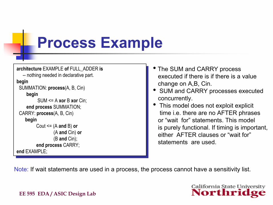
architecture EXAMPLE of FULL_ADDER is-- nothing needed in declarative part.
beginSUMMATION: process(A, B, Cin)
beginSUM <= A xor B xor Cin;
end process SUMMATION;CARRY: process(A, B, Cin)
beginCout <= (A and B) or
(A and Cin) or(B and Cin);
end process CARRY;end EXAMPLE;
architecture EXAMPLE of FULL_ADDER is-- nothing needed in declarative part.
beginSUMMATION: process(A, B, Cin)
beginSUM <= A xor B xor Cin;
end process SUMMATION;CARRY: process(A, B, Cin)
beginCout <= (A and B) or
(A and Cin) or(B and Cin);
end process CARRY;end EXAMPLE;
• The SUM and CARRY processexecuted if there is if there is a value change on A,B, Cin.
• SUM and CARRY processes executedconcurrently.
• This model does not exploit explicit time i.e. there are no AFTER phrases
or “wait for” statements. This model is purely functional. If timing is important,either AFTER clauses or “wait for”statements are used.
Note: If wait statements are used in a process, the process cannot have a sensitivity list.
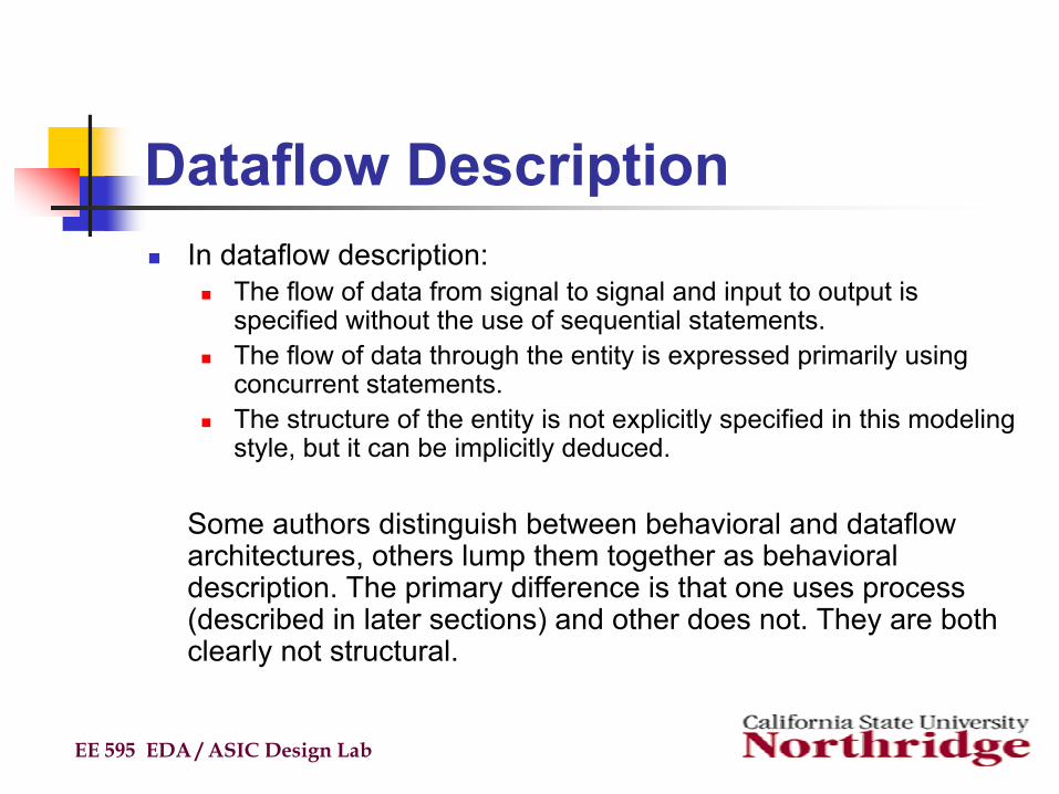
Dataflow DescriptionIn dataflow description:
The flow of data from signal to signal and input to output is specified without the use of sequential statements.The flow of data through the entity is expressed primarily usingconcurrent statements.The structure of the entity is not explicitly specified in this modeling style, but it can be implicitly deduced.
Some authors distinguish between behavioral and dataflow architectures, others lump them together as behavioral description. The primary difference is that one uses process (described in later sections) and other does not. They are both clearly not structural.
EE 595 EDA / ASIC Design Lab
Dataflow Description (cont’d)
EE 595 EDA / ASIC Design Lab
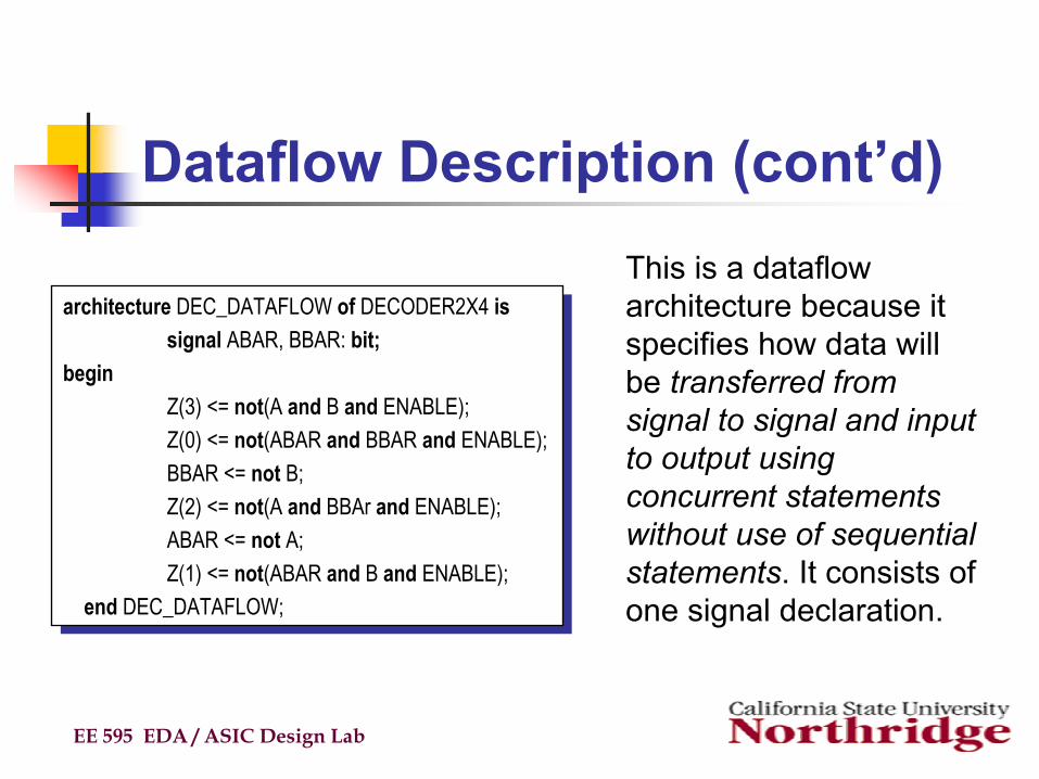
architecture DEC_DATAFLOW of DECODER2X4 issignal ABAR, BBAR: bit;
beginZ(3) <= not(A and B and ENABLE);Z(0) <= not(ABAR and BBAR and ENABLE);BBAR <= not B;Z(2) <= not(A and BBAr and ENABLE);ABAR <= not A;Z(1) <= not(ABAR and B and ENABLE);
end DEC_DATAFLOW;
architecture DEC_DATAFLOW of DECODER2X4 issignal ABAR, BBAR: bit;
beginZ(3) <= not(A and B and ENABLE);Z(0) <= not(ABAR and BBAR and ENABLE);BBAR <= not B;Z(2) <= not(A and BBAr and ENABLE);ABAR <= not A;Z(1) <= not(ABAR and B and ENABLE);
end DEC_DATAFLOW;
This is a dataflow architecture because it specifies how data will be transferred from signal to signal and input to output using concurrent statements without use of sequential statements. It consists of one signal declaration.
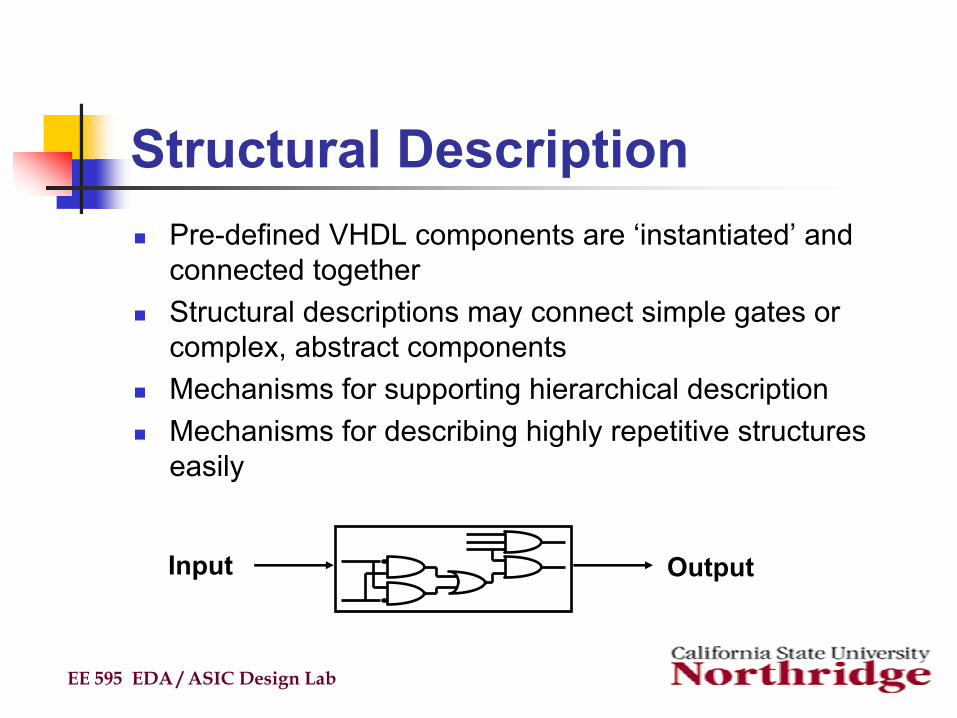
Structural DescriptionPre-defined VHDL components are ‘instantiated’ and connected togetherStructural descriptions may connect simple gates or complex, abstract componentsMechanisms for supporting hierarchical descriptionMechanisms for describing highly repetitive structures easily
EE 595 EDA / ASIC Design Lab
Input Output
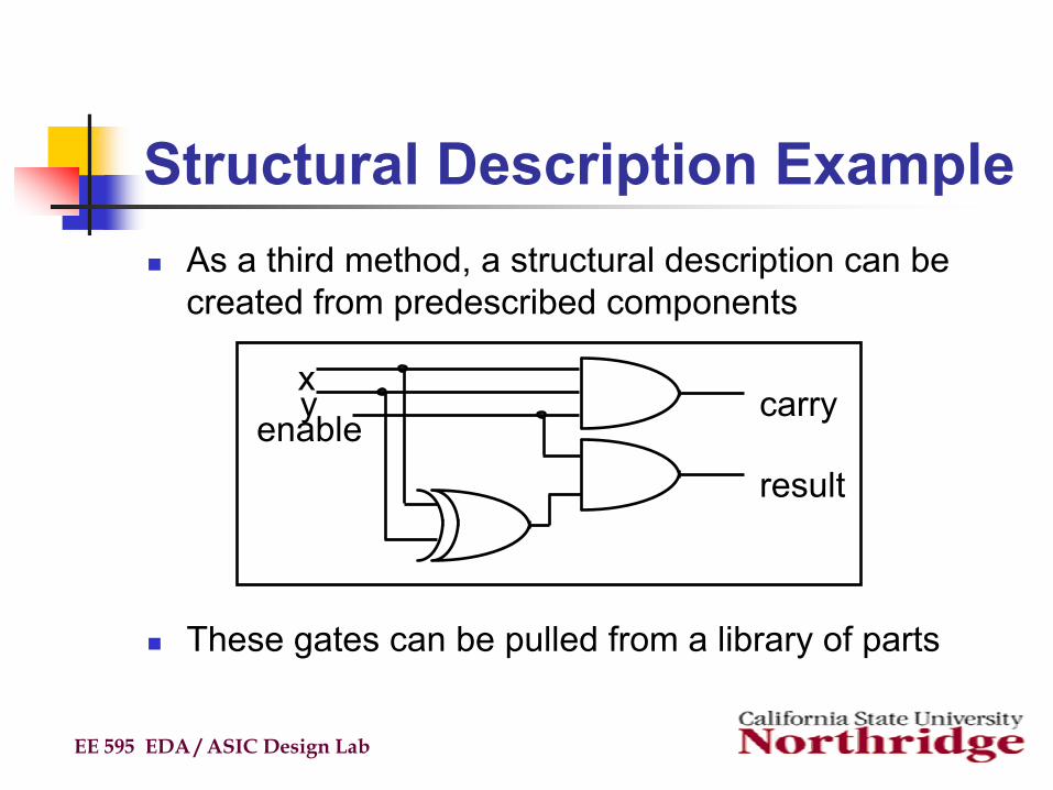
Structural Description ExampleAs a third method, a structural description can be created from predescribed components
These gates can be pulled from a library of parts
EE 595 EDA / ASIC Design Lab
xy
enablecarry
result
Structural Description Example (cont’d)
EE 595 EDA / ASIC Design Lab
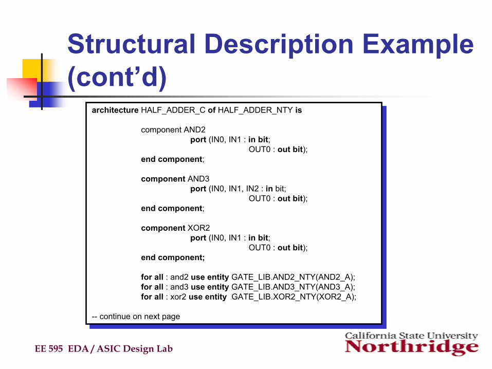
architecture HALF_ADDER_C of HALF_ADDER_NTY is
component AND2port (IN0, IN1 : in bit;
OUT0 : out bit);end component;
component AND3port (IN0, IN1, IN2 : in bit;
OUT0 : out bit);end component;
component XOR2port (IN0, IN1 : in bit;
OUT0 : out bit);end component;
for all : and2 use entity GATE_LIB.AND2_NTY(AND2_A);for all : and3 use entity GATE_LIB.AND3_NTY(AND3_A);for all : xor2 use entity GATE_LIB.XOR2_NTY(XOR2_A);
-- continue on next page
Structural Description Example (cont’d)
EE 595 EDA / ASIC Design Lab
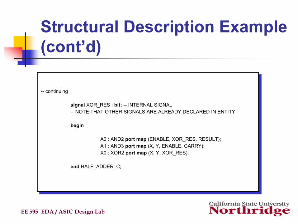
-- continuing
signal XOR_RES : bit; -- INTERNAL SIGNAL-- NOTE THAT OTHER SIGNALS ARE ALREADY DECLARED IN ENTITY
begin
A0 : AND2 port map (ENABLE, XOR_RES, RESULT);A1 : AND3 port map (X, Y, ENABLE, CARRY);X0 : XOR2 port map (X, Y, XOR_RES);
end HALF_ADDER_C;
-- continuing
signal XOR_RES : bit; -- INTERNAL SIGNAL-- NOTE THAT OTHER SIGNALS ARE ALREADY DECLARED IN ENTITY
begin
A0 : AND2 port map (ENABLE, XOR_RES, RESULT);A1 : AND3 port map (X, Y, ENABLE, CARRY);X0 : XOR2 port map (X, Y, XOR_RES);
end HALF_ADDER_C;
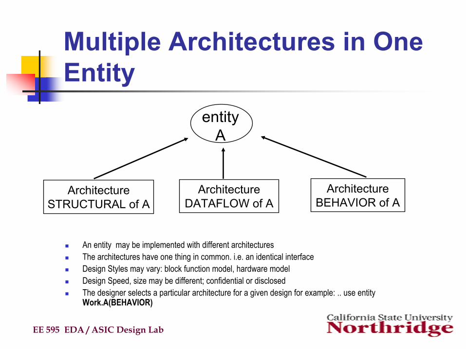
Multiple Architectures in One Entity
An entity may be implemented with different architecturesThe architectures have one thing in common. i.e. an identical interfaceDesign Styles may vary: block function model, hardware modelDesign Speed, size may be different; confidential or disclosedThe designer selects a particular architecture for a given design for example: .. use entity Work.A(BEHAVIOR)
EE 595 EDA / ASIC Design Lab
ArchitectureSTRUCTURAL of A
ArchitectureDATAFLOW of A
ArchitectureBEHAVIOR of A
entityA
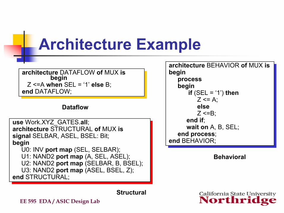
Architecture Example
EE 595 EDA / ASIC Design Lab
architecture DATAFLOW of MUX isbegin
Z <=A when SEL = ‘1’ else B;end DATAFLOW;
architecture DATAFLOW of MUX isbegin
Z <=A when SEL = ‘1’ else B;end DATAFLOW;
architecture BEHAVIOR of MUX isbegin
process begin
if (SEL = ‘1’) thenZ <= A;elseZ <=B;
end if;wait on A, B, SEL;
end process;end BEHAVIOR;
architecture BEHAVIOR of MUX isbegin
process begin
if (SEL = ‘1’) thenZ <= A;elseZ <=B;
end if;wait on A, B, SEL;
end process;end BEHAVIOR;
use Work.XYZ_GATES.all;architecture STRUCTURAL of MUX issignal SELBAR, ASEL, BSEL: Bit;begin
U0: INV port map (SEL, SELBAR);U1: NAND2 port map (A, SEL, ASEL);U2: NAND2 port map (SELBAR, B, BSEL);U3: NAND2 port map (ASEL, BSEL, Z);
end STRUCTURAL;
use Work.XYZ_GATES.all;architecture STRUCTURAL of MUX issignal SELBAR, ASEL, BSEL: Bit;begin
U0: INV port map (SEL, SELBAR);U1: NAND2 port map (A, SEL, ASEL);U2: NAND2 port map (SELBAR, B, BSEL);U3: NAND2 port map (ASEL, BSEL, Z);
end STRUCTURAL;
Dataflow
Structural
Behavioral
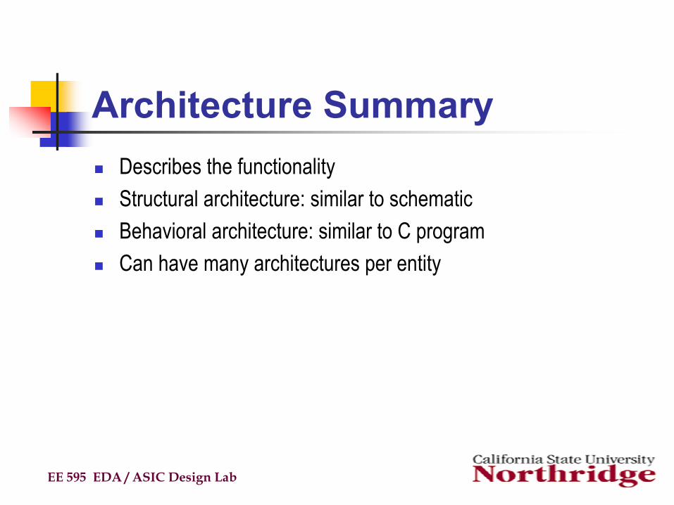
Architecture SummaryDescribes the functionalityStructural architecture: similar to schematicBehavioral architecture: similar to C programCan have many architectures per entity
EE 595 EDA / ASIC Design Lab
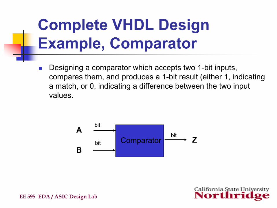
Complete VHDL Design Example, Comparator
Designing a comparator which accepts two 1-bit inputs, compares them, and produces a 1-bit result (either 1, indicating a match, or 0, indicating a difference between the two input values.
EE 595 EDA / ASIC Design Lab
A
BComparator Z
bit
bitbit
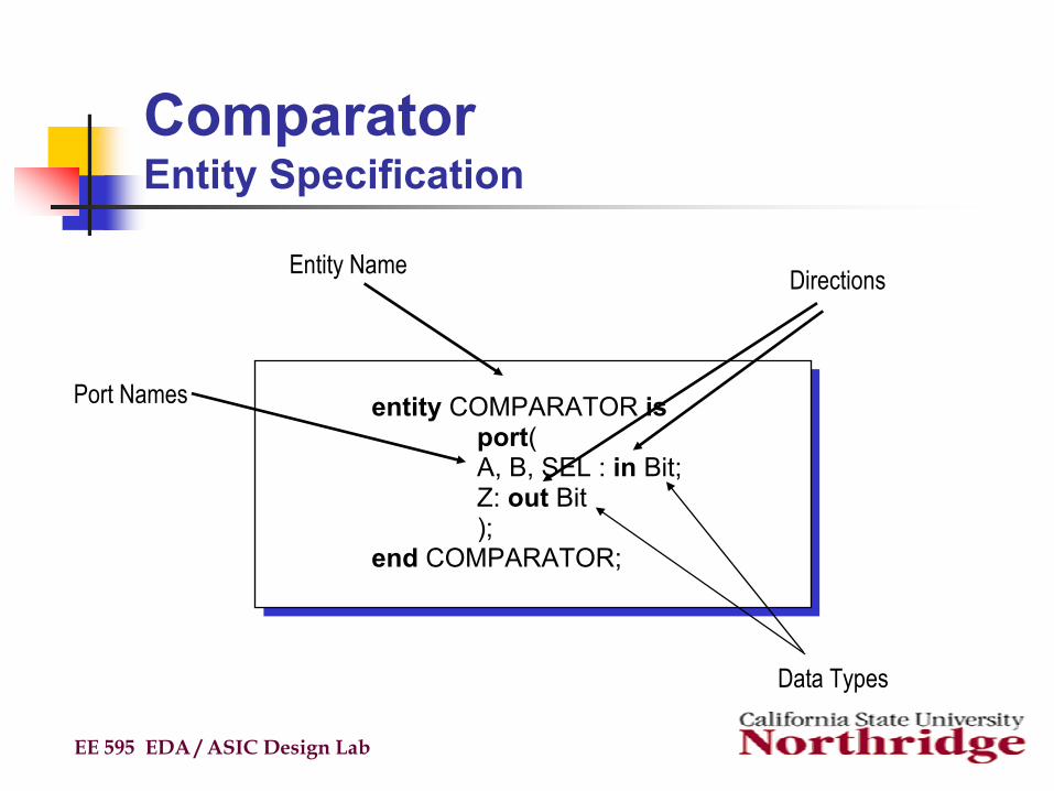
Comparator Entity Specification
EE 595 EDA / ASIC Design Lab
entity COMPARATOR isport(A, B, SEL : in Bit;Z: out Bit);
end COMPARATOR;
entity COMPARATOR isport(A, B, SEL : in Bit;Z: out Bit);
end COMPARATOR;
Port Names
DirectionsEntity Name
Data Types
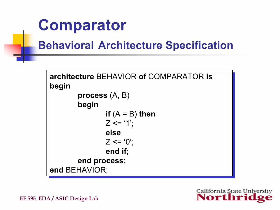
ComparatorBehavioral Architecture Specification
EE 595 EDA / ASIC Design Lab
architecture BEHAVIOR of COMPARATOR isbegin
process (A, B)begin
if (A = B) thenZ <= ‘1’;elseZ <= ‘0’;end if;
end process;end BEHAVIOR;
architecture BEHAVIOR of COMPARATOR isbegin
process (A, B)begin
if (A = B) thenZ <= ‘1’;elseZ <= ‘0’;end if;
end process;end BEHAVIOR;
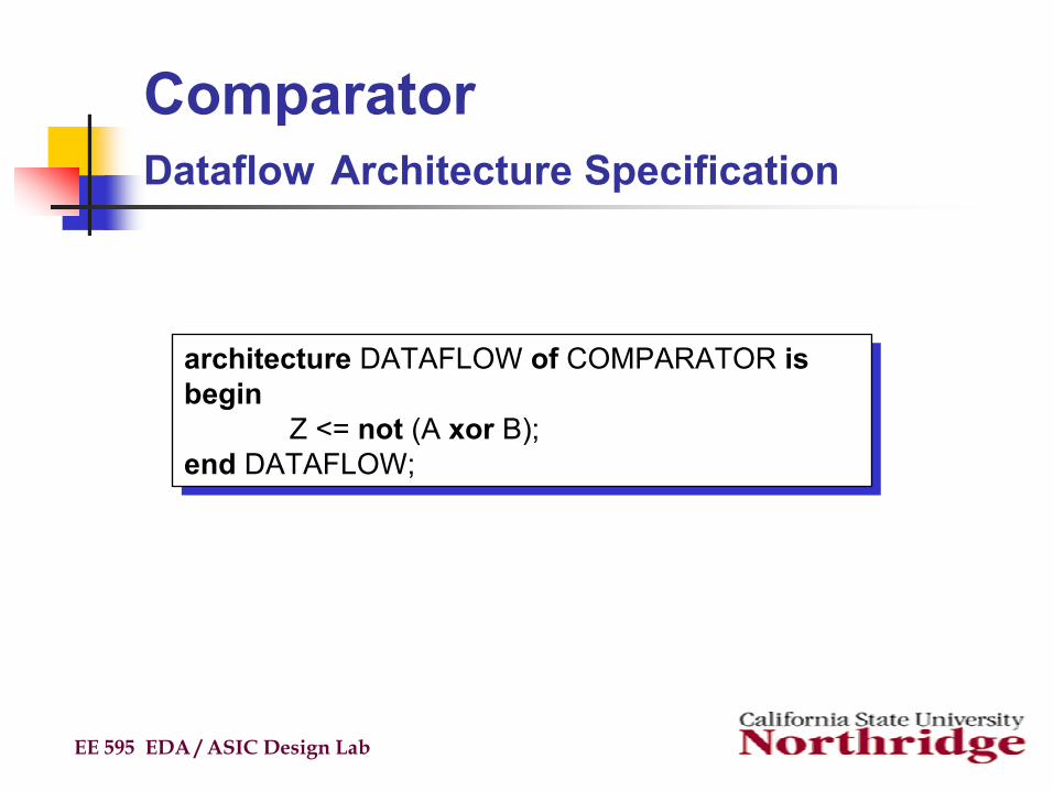
ComparatorDataflow Architecture Specification
EE 595 EDA / ASIC Design Lab
architecture DATAFLOW of COMPARATOR isbegin
Z <= not (A xor B);end DATAFLOW;
architecture DATAFLOW of COMPARATOR isbegin
Z <= not (A xor B);end DATAFLOW;
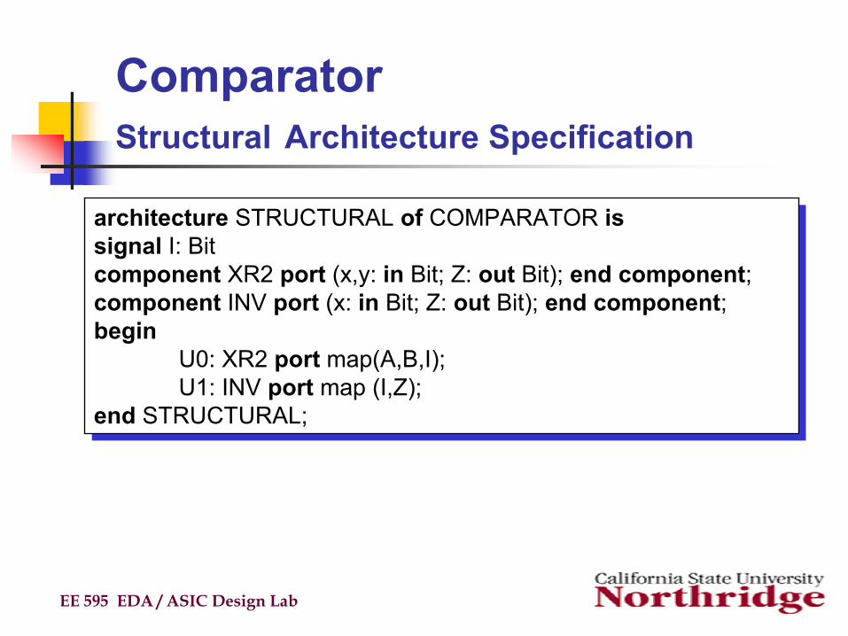
ComparatorStructural Architecture Specification
EE 595 EDA / ASIC Design Lab
architecture STRUCTURAL of COMPARATOR issignal I: Bitcomponent XR2 port (x,y: in Bit; Z: out Bit); end component;component INV port (x: in Bit; Z: out Bit); end component;begin
U0: XR2 port map(A,B,I);U1: INV port map (I,Z);
end STRUCTURAL;
architecture STRUCTURAL of COMPARATOR issignal I: Bitcomponent XR2 port (x,y: in Bit; Z: out Bit); end component;component INV port (x: in Bit; Z: out Bit); end component;begin
U0: XR2 port map(A,B,I);U1: INV port map (I,Z);
end STRUCTURAL;
Packages and LibrariesUser defined constructs declared inside architectures and entities are not visible to other VHDL components
Scope of subprograms, user defined data types, constants, and signals is limited to the VHDL components in which they are declaredPackages and libraries provide the ability to reuse constructs in multiple entities and architecturesItems declared in packages can be used (i.e. included) in other VHDL components
EE 595 EDA / ASIC Design Lab
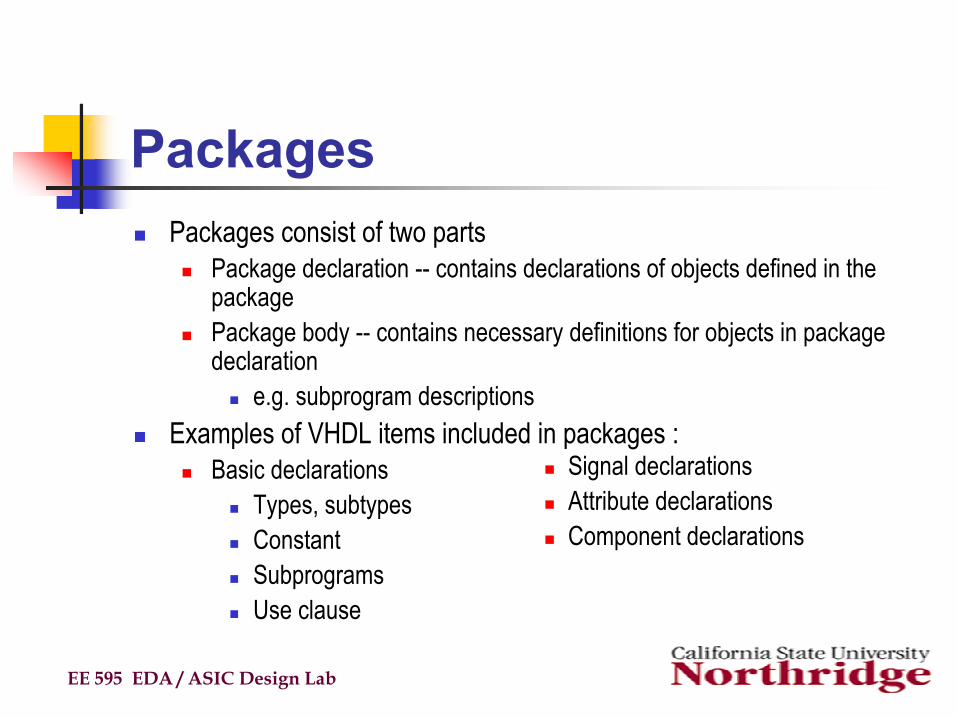
PackagesPackages consist of two parts
Package declaration -- contains declarations of objects defined in the packagePackage body -- contains necessary definitions for objects in package declaration
e.g. subprogram descriptionsExamples of VHDL items included in packages :
Basic declarationsTypes, subtypesConstantSubprogramsUse clause
EE 595 EDA / ASIC Design Lab
Signal declarationsAttribute declarationsComponent declarations
Packages (cont’d)
EE 595 EDA / ASIC Design Lab
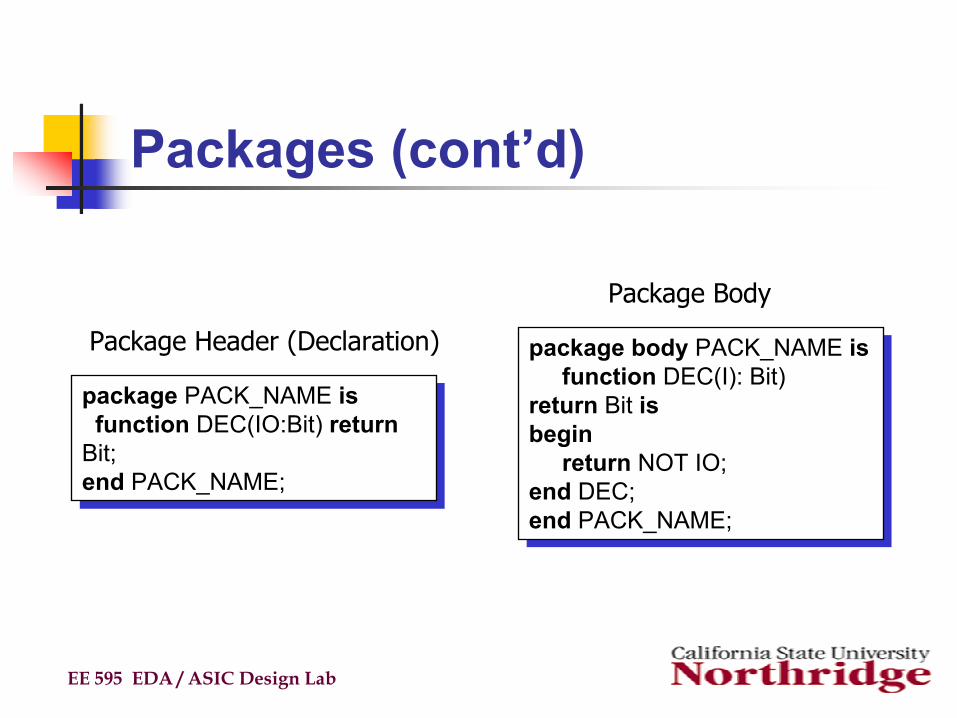
package body PACK_NAME isfunction DEC(I): Bit)
return Bit isbegin
return NOT IO;end DEC;end PACK_NAME;
package body PACK_NAME isfunction DEC(I): Bit)
return Bit isbegin
return NOT IO;end DEC;end PACK_NAME;
package PACK_NAME isfunction DEC(IO:Bit) return
Bit;end PACK_NAME;
package PACK_NAME isfunction DEC(IO:Bit) return
Bit;end PACK_NAME;
Package Header (Declaration)
Package Body
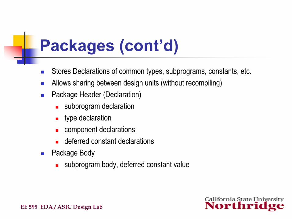
Packages (cont’d)Stores Declarations of common types, subprograms, constants, etc.Allows sharing between design units (without recompiling)Package Header (Declaration)
subprogram declarationtype declarationcomponent declarationsdeferred constant declarations
Package Bodysubprogram body, deferred constant value
EE 595 EDA / ASIC Design Lab
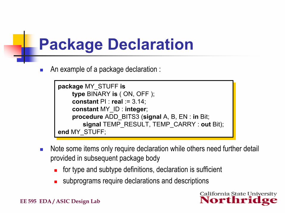
Package DeclarationAn example of a package declaration :
Note some items only require declaration while others need further detail provided in subsequent package body
for type and subtype definitions, declaration is sufficientsubprograms require declarations and descriptions
EE 595 EDA / ASIC Design Lab
package MY_STUFF istype BINARY is ( ON, OFF );constant PI : real := 3.14;constant MY_ID : integer;procedure ADD_BITS3 (signal A, B, EN : in Bit;
signal TEMP_RESULT, TEMP_CARRY : out Bit);end MY_STUFF;
package MY_STUFF istype BINARY is ( ON, OFF );constant PI : real := 3.14;constant MY_ID : integer;procedure ADD_BITS3 (signal A, B, EN : in Bit;
signal TEMP_RESULT, TEMP_CARRY : out Bit);end MY_STUFF;
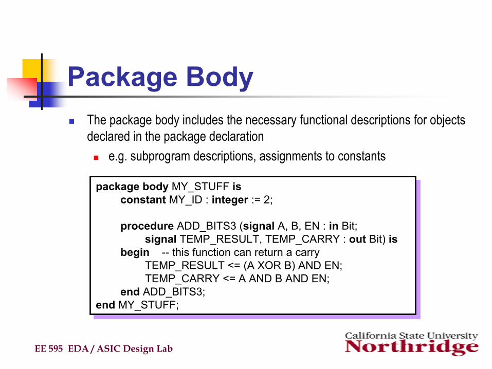
Package BodyThe package body includes the necessary functional descriptions for objects declared in the package declaration
e.g. subprogram descriptions, assignments to constants
EE 595 EDA / ASIC Design Lab
package body MY_STUFF isconstant MY_ID : integer := 2;
procedure ADD_BITS3 (signal A, B, EN : in Bit;signal TEMP_RESULT, TEMP_CARRY : out Bit) is
begin -- this function can return a carryTEMP_RESULT <= (A XOR B) AND EN;TEMP_CARRY <= A AND B AND EN;
end ADD_BITS3;end MY_STUFF;
package body MY_STUFF isconstant MY_ID : integer := 2;
procedure ADD_BITS3 (signal A, B, EN : in Bit;signal TEMP_RESULT, TEMP_CARRY : out Bit) is
begin -- this function can return a carryTEMP_RESULT <= (A XOR B) AND EN;TEMP_CARRY <= A AND B AND EN;
end ADD_BITS3;end MY_STUFF;
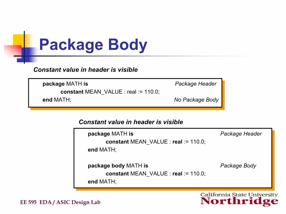
Package Body
EE 595 EDA / ASIC Design Lab
package MATH is Package Headerconstant MEAN_VALUE : real := 110.0;
end MATH; No Package Body
package MATH is Package Headerconstant MEAN_VALUE : real := 110.0;
end MATH; No Package Body
package MATH is Package Headerconstant MEAN_VALUE : real := 110.0;
end MATH;
package body MATH is Package Bodyconstant MEAN_VALUE : real := 110.0;
end MATH;
package MATH is Package Headerconstant MEAN_VALUE : real := 110.0;
end MATH;
package body MATH is Package Bodyconstant MEAN_VALUE : real := 110.0;
end MATH;
Constant value in header is visible
Constant value in header is visible
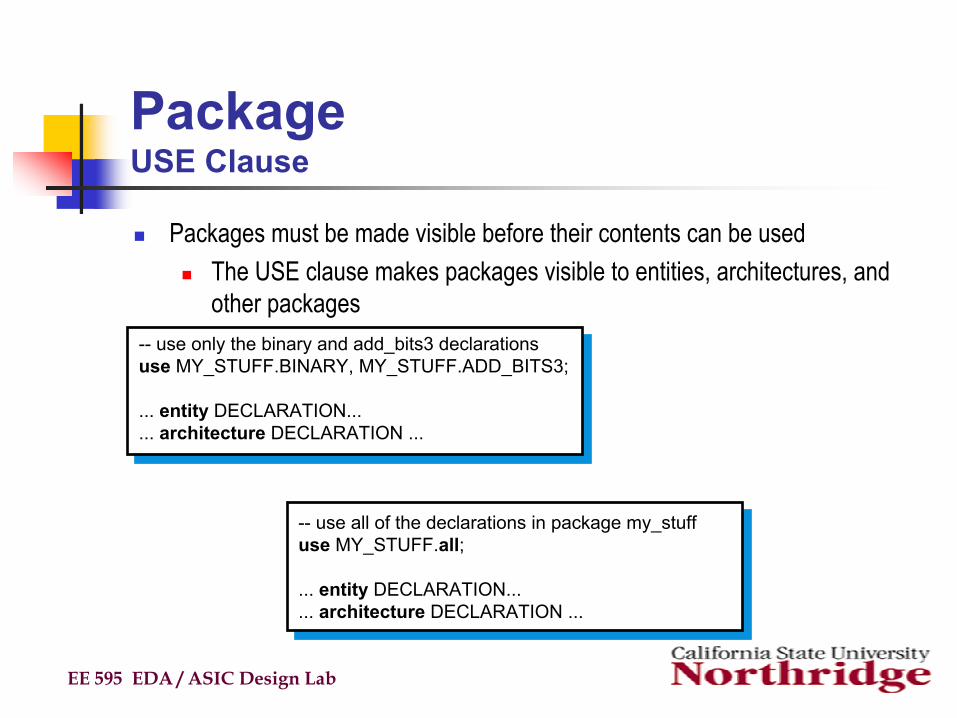
PackageUSE Clause
Packages must be made visible before their contents can be usedThe USE clause makes packages visible to entities, architectures, and other packages
EE 595 EDA / ASIC Design Lab
-- use only the binary and add_bits3 declarationsuse MY_STUFF.BINARY, MY_STUFF.ADD_BITS3;
... entity DECLARATION...
... architecture DECLARATION ...
-- use only the binary and add_bits3 declarationsuse MY_STUFF.BINARY, MY_STUFF.ADD_BITS3;
... entity DECLARATION...
... architecture DECLARATION ...
-- use all of the declarations in package my_stuffuse MY_STUFF.all;
... entity DECLARATION...
... architecture DECLARATION ...
-- use all of the declarations in package my_stuffuse MY_STUFF.all;
... entity DECLARATION...
... architecture DECLARATION ...
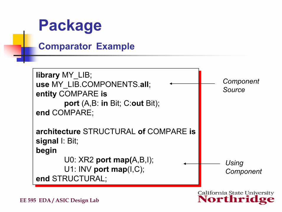
PackageComparator Example
EE 595 EDA / ASIC Design Lab
library MY_LIB;use MY_LIB.COMPONENTS.all;entity COMPARE is
port (A,B: in Bit; C:out Bit);end COMPARE;
architecture STRUCTURAL of COMPARE issignal I: Bit;begin
U0: XR2 port map(A,B,I);U1: INV port map(I,C);
end STRUCTURAL;
library MY_LIB;use MY_LIB.COMPONENTS.all;entity COMPARE is
port (A,B: in Bit; C:out Bit);end COMPARE;
architecture STRUCTURAL of COMPARE issignal I: Bit;begin
U0: XR2 port map(A,B,I);U1: INV port map(I,C);
end STRUCTURAL;
ComponentSource
Using Component
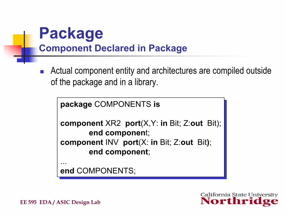
PackageComponent Declared in Package
Actual component entity and architectures are compiled outside of the package and in a library.
EE 595 EDA / ASIC Design Lab
package COMPONENTS is
component XR2 port(X,Y: in Bit; Z:out Bit);end component;
component INV port(X: in Bit; Z:out Bit);end component;
...end COMPONENTS;
package COMPONENTS is
component XR2 port(X,Y: in Bit; Z:out Bit);end component;
component INV port(X: in Bit; Z:out Bit);end component;
...end COMPONENTS;
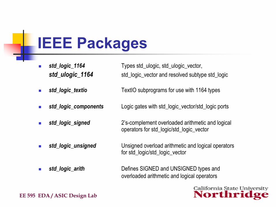
IEEE Packagesstd_logic_1164 Types std_ulogic, std_ulogic_vector, std_ulogic_1164 std_logic_vector and resolved subtype std_logic
std_logic_textio TextIO subprograms for use with 1164 types
std_logic_components Logic gates with std_logic_vector/std_logic ports
std_logic_signed 2’s-complement overloaded arithmetic and logical operators for std_logic/std_logic_vector
std_logic_unsigned Unsigned overload arithmetic and logical operators for std_logic/std_logic_vector
std_logic_arith Defines SIGNED and UNSIGNED types and overloaded arithmetic and logical operators
EE 595 EDA / ASIC Design Lab
Libraries
Design Units are stored in librariesNeed to declare library before using itEvery vendor will have a different library formatOne design can use many libraries
EE 595 EDA / ASIC Design Lab
Libraries (cont’d)Library contains compiled entities, architectures, packages and configuration. They store VHDL packages, user designs, and ASIC vendor components.The results of a VHDL compilation are kept inside of a library for subsequent simulation, or for use in other designs.
EE 595 EDA / ASIC Design Lab
Libraries (cont’d)A library can contain:
A package - shared declarationAn entity - shared designsAn architecture - shared design implementationA configuration - shared design version.
The benefits of using a library is to promote the sharing of previously compiled designs and the source design units need not be disclosed to all users.
EE 595 EDA / ASIC Design Lab
Libraries (cont’d)Analogous to directories of files
VHDL libraries contain analyzed (i.e. compiled) VHDL entities, architectures, and packages
Facilitate administration of configuration and revision controlE.g. libraries of previous designs
Libraries accessed via an assigned logical nameCurrent design unit is compiled into the Work libraryBoth Work and STD libraries are always availableMany other libraries usually supplied by VHDL simulator vendor
E.g. proprietary libraries and IEEE standard libraries
EE 595 EDA / ASIC Design Lab
Libraries (cont’d)Certain VHDL objects are kept by name in a library:
package -- shared declarationsarchitecture -- shared designsentity -- shared design interfacesconfigurations -- shared design versions
VHDL expects: -- your working library to be called Work-- standard library called Std-- standard package standard-- text input/output Textio
Users can have other resource libraries for:synthesis -- project designsASIC vendor library -- simulation, components
EE 595 EDA / ASIC Design Lab
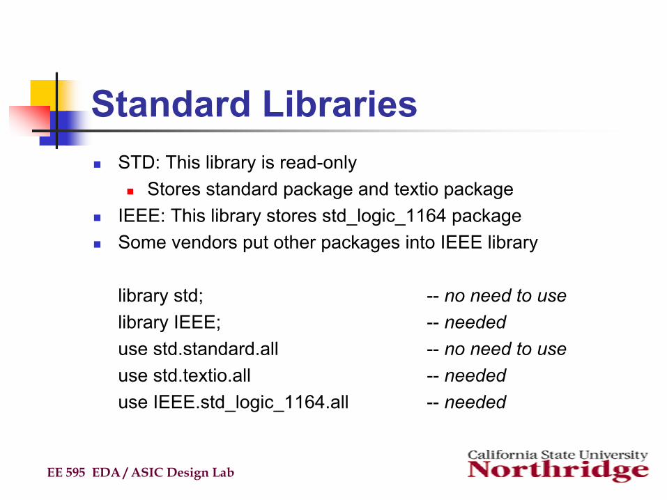
Standard LibrariesSTD: This library is read-only
Stores standard package and textio packageIEEE: This library stores std_logic_1164 packageSome vendors put other packages into IEEE library
library std; -- no need to uselibrary IEEE; -- neededuse std.standard.all -- no need to useuse std.textio.all -- neededuse IEEE.std_logic_1164.all -- needed
EE 595 EDA / ASIC Design Lab
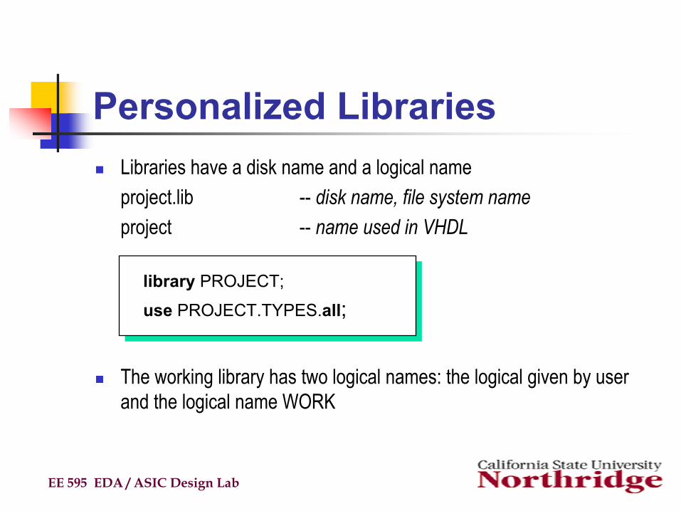
Personalized LibrariesLibraries have a disk name and a logical nameproject.lib -- disk name, file system nameproject -- name used in VHDL
The working library has two logical names: the logical given by user and the logical name WORK
EE 595 EDA / ASIC Design Lab
library PROJECT;
use PROJECT.TYPES.all;
Vendor Libraries
EE 595 EDA / ASIC Design Lab
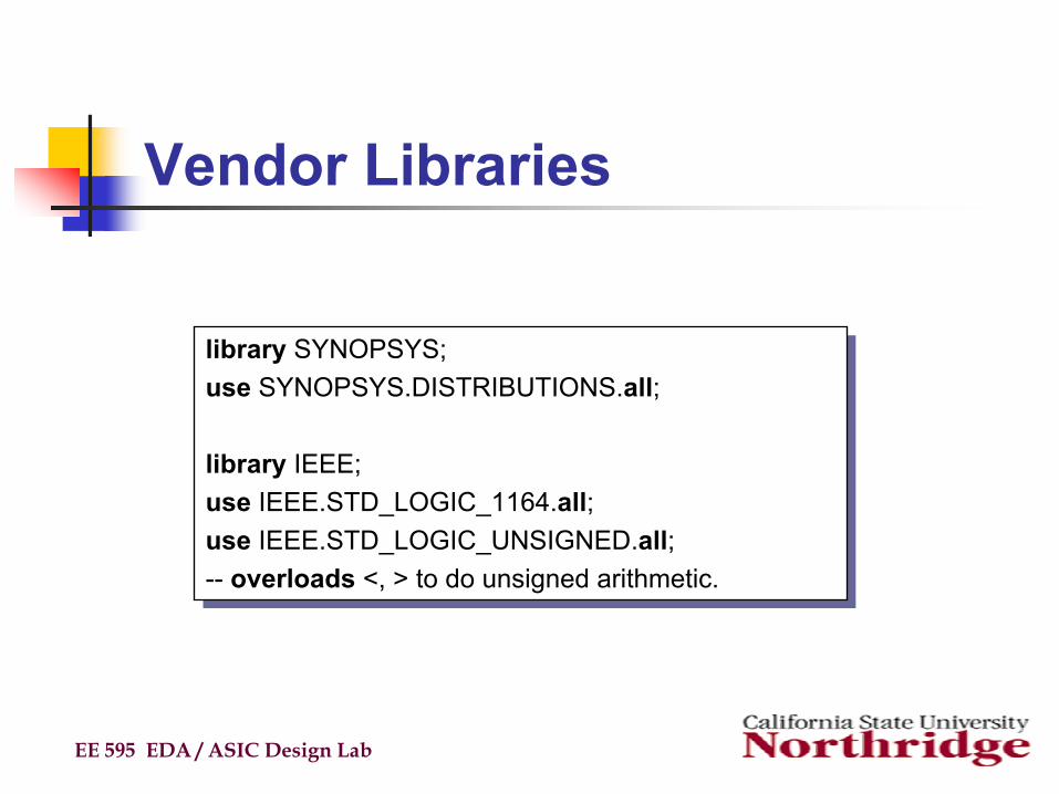
library SYNOPSYS;use SYNOPSYS.DISTRIBUTIONS.all;
library IEEE;use IEEE.STD_LOGIC_1164.all;use IEEE.STD_LOGIC_UNSIGNED.all;-- overloads <, > to do unsigned arithmetic.
library SYNOPSYS;use SYNOPSYS.DISTRIBUTIONS.all;
library IEEE;use IEEE.STD_LOGIC_1164.all;use IEEE.STD_LOGIC_UNSIGNED.all;-- overloads <, > to do unsigned arithmetic.
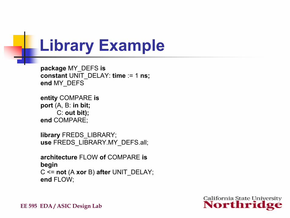
Library Examplepackage MY_DEFS isconstant UNIT_DELAY: time := 1 ns;end MY_DEFS
entity COMPARE isport (A, B: in bit;
C: out bit);end COMPARE;
library FREDS_LIBRARY;use FREDS_LIBRARY.MY_DEFS.all;
architecture FLOW of COMPARE isbeginC <= not (A xor B) after UNIT_DELAY;end FLOW;
EE 595 EDA / ASIC Design Lab
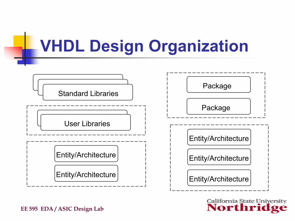
VHDL Design Organization
EE 595 EDA / ASIC Design Lab
Standard Libraries
User Libraries
Entity/Architecture
Entity/Architecture
Package
Package
Entity/Architecture
Entity/Architecture
Entity/Architecture
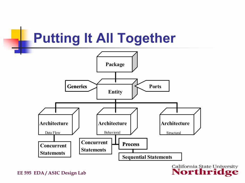
Putting It All Together
EE 595 EDA / ASIC Design Lab
GenericsGenerics PortsPortsEntity
Architecture Architecture Architecture
ConcurrentStatements
ProcessProcess
Sequential Statements
ConcurrentStatements
Package
Data Flow Behavioral Structural
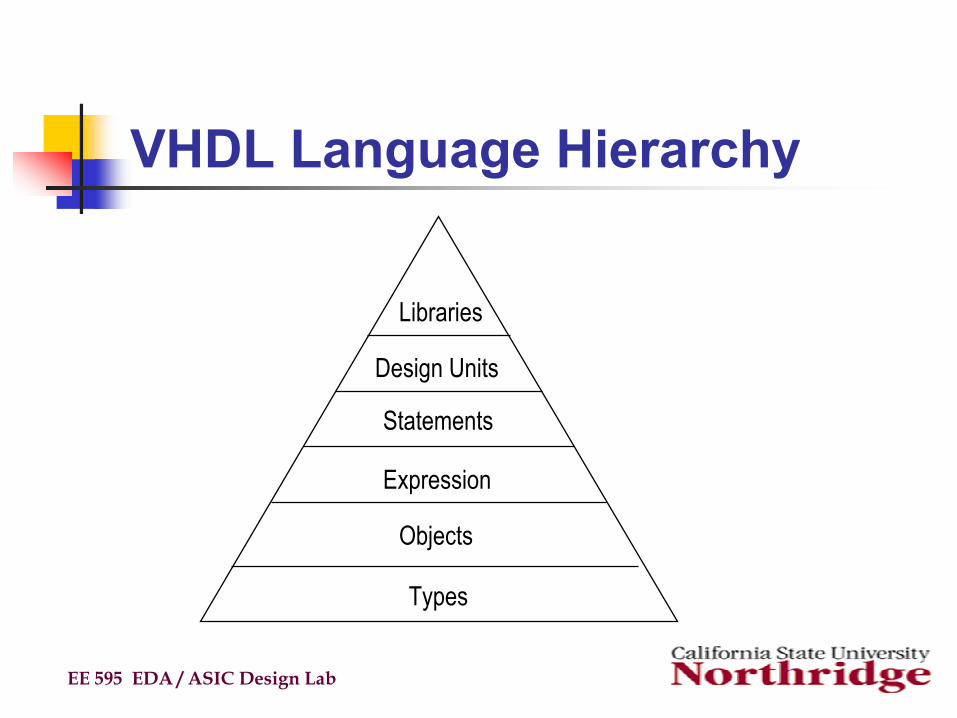
VHDL Language Hierarchy
EE 595 EDA / ASIC Design Lab
Libraries
Design Units
Statements
Expression
Objects
Types