Embed Size (px)
Citation preview

Geiger Tube Theory, Dead Time
22. 02 DI eiger Counters Prof. Michael hort
Questions to Start
2
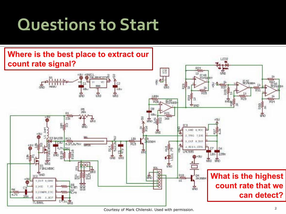
Where is the best place to extract our count rate signal?
What is the highest count rate that we
can detect? Courtesy of Mark Chilenski. Used with permission.
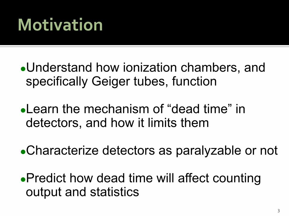
Motivation
Understand how ioni ation chambers, and specificall eiger tubes, function earn the mechanism of dead time in detectors, and how it limits them Characteri e detectors as paral able or not Predict how dead time will affect counting output and statistics
3
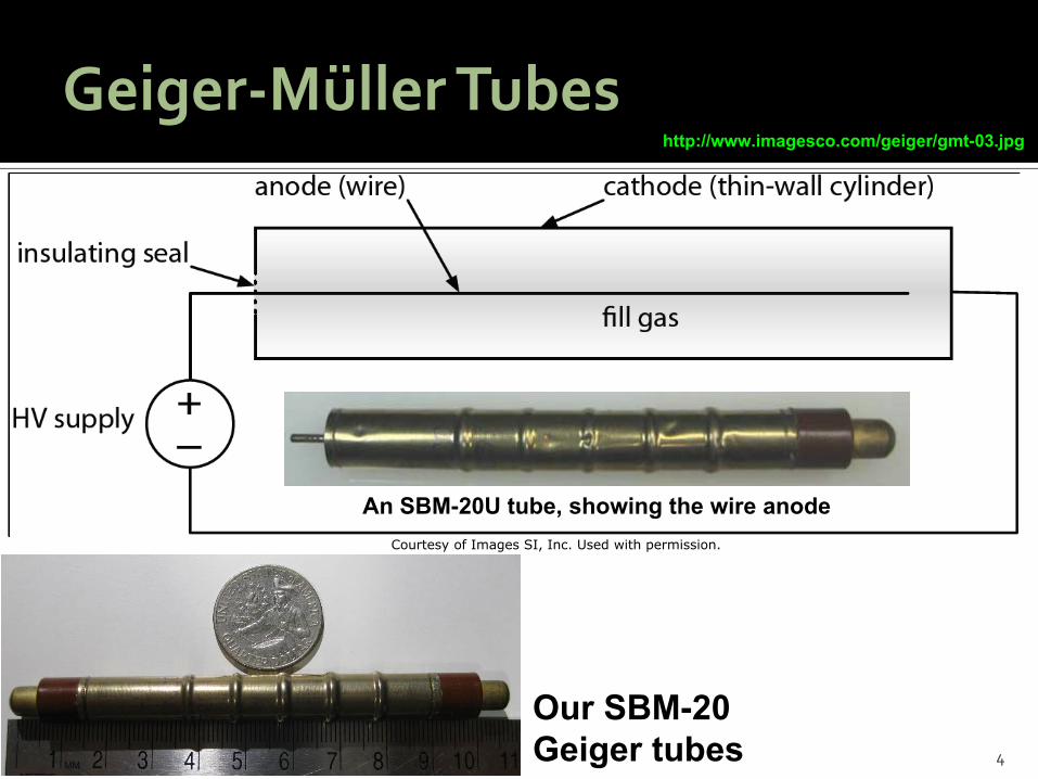
Geiger-Müller Tubes http://www.imagesco.com/geiger/gmt-03.jpg
4
An SBM-20U tube, showing the wire anode Courtesy of Images SI, Inc. Used with permission.
Our SBM-20 Geiger tubes

Our SBM-20 Geiger-Müller Tubes
Wall thic ness: 0 m steel
5
Wall Densit : 8 g/cm3
Assume 1 atm e ual gas mi ture
For more information, see: http://www.gstube.com/data/2398/
Tube diagram © source unknown. All rights reserved. This content isexcluded from our Creative Commons license. For more information,see http://ocw.mit.edu/help/faq-fair-use/.

Ionization Chambers
6
–
–
– –
–
– –
–
–
– – – –
–
–
–
–
–
Public domain image.
Geiger tube photo courtesy of Jeff Keyzer on Flickr.
Circuit diagram © Wiley-VCH, from J. Turner, Atoms, Radiation,and Radiation Protection (2007). All rights reserved. Thiscontent is excluded from our Creative Commons license. Formore information, see http://ocw.mit.edu/help/faq-fair-use/.
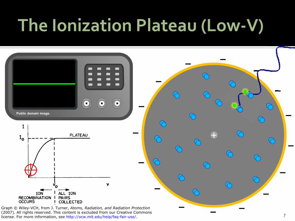
The Ionization Plateau (Low-V)
7
–
–
– –
–
– –
–
–
– – – –
–
–
–
–
–
Public domain image.
Graph © Wiley-VCH, from J. Turner, Atoms, Radiation, and Radiation Protection(2007). All rights reserved. This content is excluded from our Creative Commonslicense. For more information, see http://ocw.mit.edu/help/faq-fair-use/.

The Ionization Plateau (Med-V)
8
–
–
– –
–
– –
–
–
– – – –
–
–
–
–
–
Public domain image.
Graph © Wiley-VCH, from J. Turner, Atoms, Radiation, and Radiation Protection(2007). All rights reserved. This content is excluded from our Creative Commonslicense. For more information, see http://ocw.mit.edu/help/faq-fair-use/.

The Ionization Plateau (High-V)
9
–
–
– –
–
– –
–
–
– – – –
–
–
–
–
–
Public domain image.
Graph © Wiley-VCH, from J. Turner, Atoms, Radiation, and Radiation Protection(2007). All rights reserved. This content is excluded from our Creative Commonslicense. For more information, see http://ocw.mit.edu/help/faq-fair-use/.

The Ionization Plateau (HIGH-V)
10
–
–
– –
–
– –
–
–
– – – –
–
–
–
–
–
Public domain image.
Graph © Wiley-VCH, from J. Turner, Atoms, Radiation, and Radiation Protection(2007). All rights reserved. This content is excluded from our Creative Commonslicense. For more information, see http://ocw.mit.edu/help/faq-fair-use/.
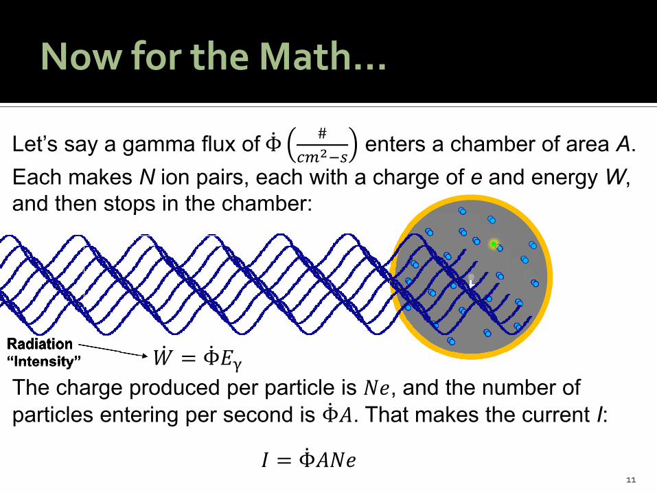
et s sa a gamma flu of Φ̇ #𝑐𝑐𝑐𝑐2−𝑠𝑠
enters a chamber of area A. ach ma es N ion pairs, each with a charge of e and energ W,
and then stops in the chamber:
The charge produced per particle is 𝑁𝑁𝑁𝑁, and the number of particles entering per second is Φ̇
Now for the Math…
𝐴𝐴. That ma es the current I:
11 𝐼𝐼 = Φ̇𝐴𝐴𝑁𝑁𝑁𝑁
and then stops
�̇�𝑊 = Φ̇𝐸𝐸γ Radiation “Intensity”
and then stopsand then stops
“Intensity” Radiation Radiation

et s sa a ach ma e
and then st
gamma flu of Φ̇ #𝑐𝑐𝑐𝑐2−𝑠𝑠
enters a chamber of area A. s N ion pairs, each with a charge of e and energ W, ops in the chamber:
ow use the radiation intensit :
Now for the Math…
12
𝐼𝐼𝐴𝐴𝑁𝑁𝑁𝑁
= Φ̇
ops in the chamber:
�̇�𝑊 = Φ̇𝐸𝐸γ Radiation “Intensity”
ops in the chamber:ops in the chamber:
“Intensity” Radiation Radiation
𝐼𝐼 = Φ̇𝐴𝐴𝑁𝑁𝑁𝑁 �̇�𝑊 =𝐼𝐼
𝐴𝐴𝑁𝑁𝑁𝑁𝐸𝐸γ =
𝐼𝐼𝑊𝑊𝐴𝐴𝐸𝐸γ𝑁𝑁
𝐸𝐸γ =𝐼𝐼𝑊𝑊𝐴𝐴𝑁𝑁
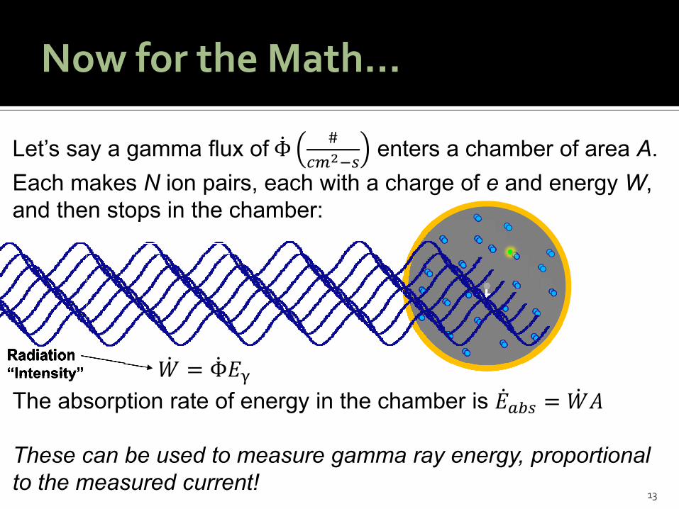
et s sa a gamma flu of Φ̇ #𝑐𝑐𝑐𝑐2−𝑠𝑠
enters a chamber of area A. ach ma es N ion pairs, each with a charge of e and energ W,
and then stops in the chamber:
The absorption rate of energ in the chamber is �̇�𝐸𝑎𝑎𝑎𝑎𝑠𝑠 = �̇�𝑊
Now for the Math…
𝐴𝐴
These can be used to measure gamma ray energy, proportional to the measured current!
13
and then stops in the chamber:
�̇�𝑊 = Φ̇𝐸𝐸γ Radiation “Intensity”
and then stops in the chamber:and then stops in the chamber:
and then stops in the chamber:and then stops in the chamber:
“Intensity” Radiation Radiation
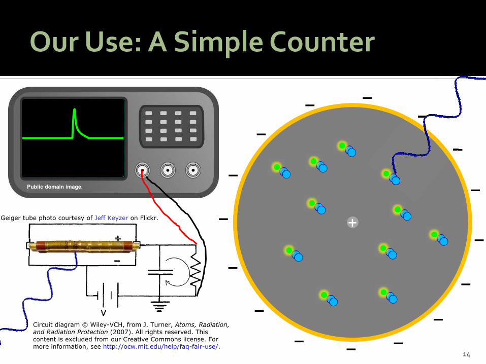
Our Use: A Simple Counter
14
–
–
– –
–
– –
–
–
– – – –
–
–
–
–
–
Public domain image.
Geiger tube photo courtesy of Jeff Keyzer on Flickr.
Circuit diagram © Wiley-VCH, from J. Turner, Atoms, Radiation,and Radiation Protection (2007). All rights reserved. Thiscontent is excluded from our Creative Commons license. Formore information, see http://ocw.mit.edu/help/faq-fair-use/.

Our Use: A Simple Counter
15
We use circuitr to detect the rising edge of the pulse from the eiger tube
et some threshold to call the edge risen
end this now digital signal to our Ds and the spea er to ma e light and nose
Public domain image.
Geiger tube photo courtesy of Jeff Keyzer on Flickr.
Circuit diagram © Wiley-VCH, from J. Turner, Atoms, Radiation,and Radiation Protection (2007). All rights reserved. Thiscontent is excluded from our Creative Commons license. Formore information, see http://ocw.mit.edu/help/faq-fair-use/.
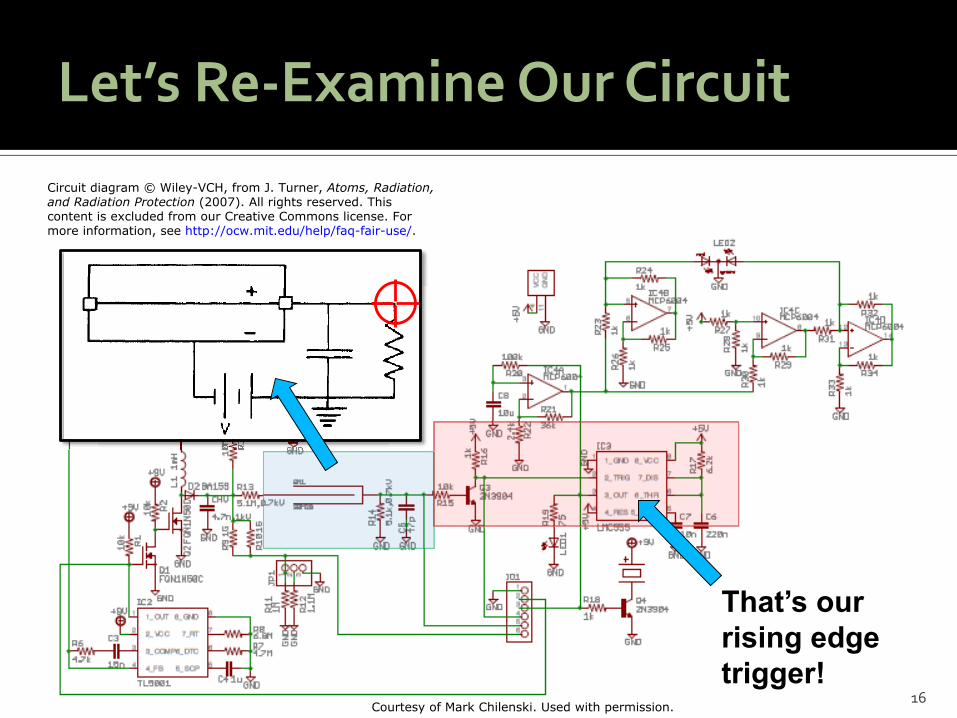
Let’s Re-Examine Our Circuit
16
That’s our rising edge trigger!
Circuit diagram © Wiley-VCH, from J. Turner, Atoms, Radiation,and Radiation Protection (2007). All rights reserved. Thiscontent is excluded from our Creative Commons license. Formore information, see http://ocw.mit.edu/help/faq-fair-use/.
Courtesy of Mark Chilenski. Used with permission.
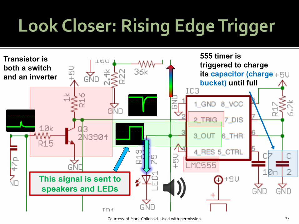
Look Closer: Rising Edge Trigger
17
Transistor is both a switch and an inverter
555 timer is triggered to charge its capacitor (charge bucket) until full
This signal is sent to speakers and LEDs
Courtesy of Mark Chilenski. Used with permission.
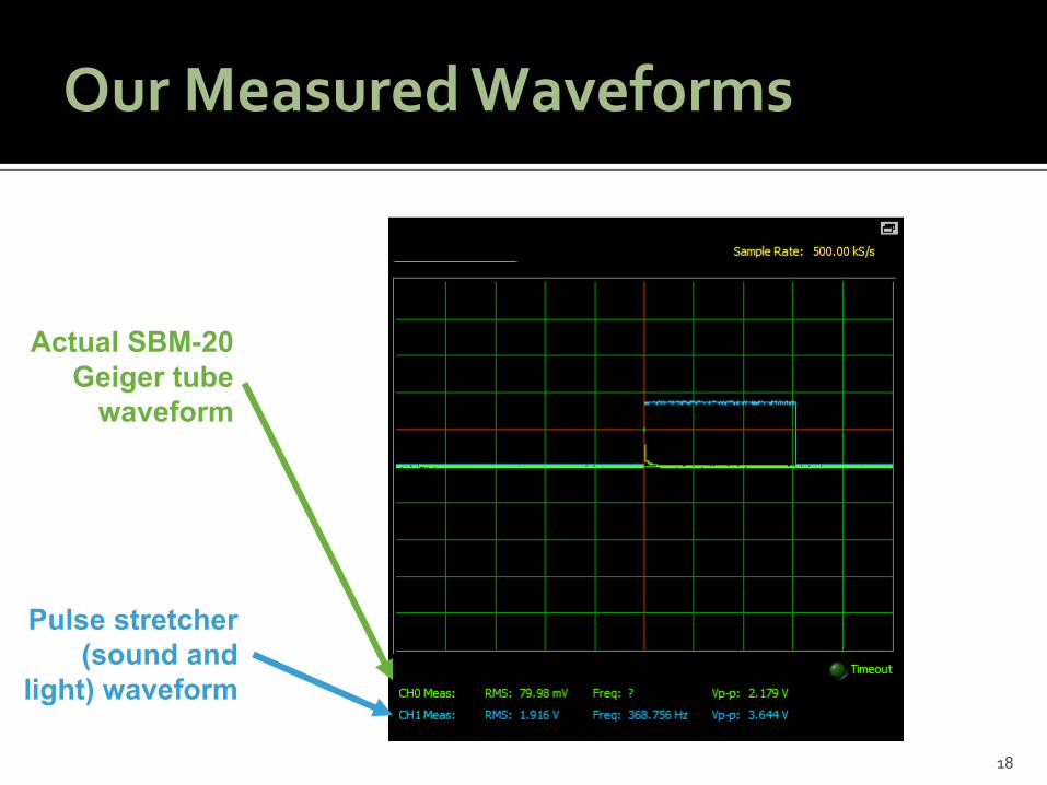
Our Measured Waveforms
18
Actual SBM-20 Geiger tube
waveform
Pulse stretcher (sound and
light) waveform

Limiting Cases: High Signal
19
What happens if LOTS of counts come in at once?
No problem!
Missed count!
This is known as “dead time,” a period when the detector is unresponsive
GM Tube
Pulse Stretcher
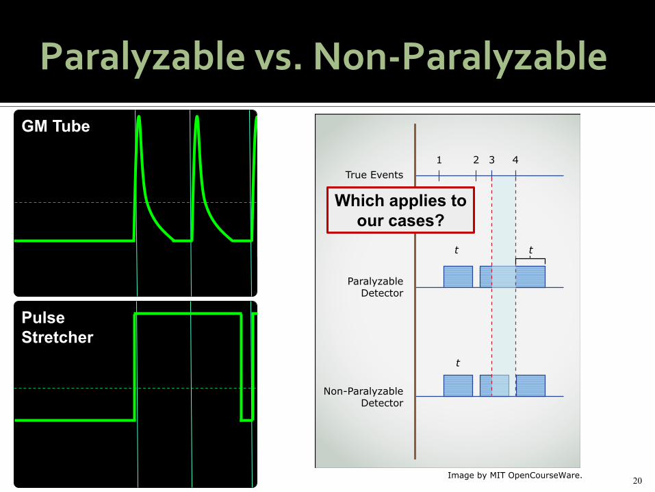
Paralyzable vs. Non-Paralyzable
Pulse Stretcher
GM Tube
20Image by MIT OpenCourseWare.
1 2 3 4True Events
ParalyzableDetector
Non-ParalyzableDetector
t t
t
Which applies to our cases?

Paralyzable vs. Non-Paralyzable
Increase count rate
21
Circuit diagram © Wiley-VCH, from J. Turner,Atoms, Radiation, and Radiation Protection(2007). All rights reserved. This content isexcluded from our Creative Commons license.For more information, see http://ocw.mit.edu/help/faq-fair-use/.
Geiger tube photo courtesyof Jeff Keyzer on Flickr.

Paralyzable vs. Non-Paralyzable
GM Tube
er rapid radiation events eep the ion current high
This maintains the circuit voltage above the rising edge trigger threshold
The M tube is therefore paralyzable, but its dead time is ver low 1 s
Geiger tube photo courtesyof Jeff Keyzer on Flickr.
22
Circuit diagram © Wiley-VCH, from J. Turner, Atoms, Radiation,and Radiation Protection (2007). All rights reserved. This contentis excluded from our Creative Commons license. For moreinformation, see http://ocw.mit.edu/help/faq-fair-use/.

Paralyzable vs. Non-Paralyzable
Pulse Stretcher
er rapid radiation events don t re trigger capacitor discharge
o additional time is spent at logic high voltage
The pulse stretcher is therefore non-paralyzable, but its dead time is ver high 1. ms
23
Thinking Ahead for the Lab
ow will ou characteri e M dead time
ow will ou characteri e pulse stretcher deadtime
Where on our circuit will ou connect thecomputer to measure counts
What other sources of dead time e ist in thes stem Hint: There are some!
24

25

MIT OpenCourseWarehttp://ocw.mit.edu
22.S902 Do-It-Yourself (DIY) Geiger CountersJanuary IAP 2015
For information about citing these materials or our Terms of Use, visit: http://ocw.mit.edu/terms.


![Geiger 2011 Presentation[1]](https://img.pdfslide.net/doc/110x75/555e97f3d8b42a6d068b4d4c/geiger-2011-presentation1.jpg)