Embed Size (px)
Citation preview

Lecture 20: Radiant Systems
Material prepared by GARD Analytics, Inc. and University of Illinoisat Urbana-Champaign under contract to the National Renewable Energy
Laboratory. All material Copyright 2002-2003 U.S.D.O.E. - All rights reserved

2
Importance of this Lecture to the Simulation of Buildings
Forced air systems tend to dominate the US market Systems are relatively easy to understand Control on air temperature pretty
straightforwardAir systems do not guarantee comfort
which is a function of other variables besides air temperature
Other systems, such as radiant systems, may be a better option for some cases
Ability to simulate different system types is critical to the fair and accurate comparison of energy consumption

3
Purpose of this Lecture
Gain an understanding of: Radiant systems overview:
characteristics, types, advantages, and potential problems
How to specify different types of radiant systems in EnergyPlus

4
Keywords Covered in this Lecture
Low Temp Radiant System:Hydronic
Construction With Internal SourceSurface:HeatTransfer (review)Radiant System Surface GroupLow Temp Radiant System:ElectricHigh Temp Radiant System
Radiant Systems Overview
Low Temperature Radiant Systems
High Temperature Radiant Systems
Hybrid Systems
6
Radiant System Overview
Conventional Forced Air Systems: aim to affect the thermal comfort of space occupants by conditioning air and delivering it to a space
Primary effect is on space air temperature Controls are simple but do not always guarantee comfort
Radiant Systems: aim to affect the thermal comfort of space occupants by modifying the radiant field within a space
Primary effect can be on surface temperatures Some systems are simply direct radiant sources Controls are more complex but inclusion of radiant
effects may result in better comfort at lower air temperatures
7
Radiant System Overview (cont’d)
Definition: system which supplies a majority of its energy to a space via radiation
Main System Types (Temperature Classifications) Low Temperature Radiant Systems High (and Medium) Temperature Radiant Systems
(heating only) Indoor Air Quality (IAQ) Issues
IAQ linked to introduction of outside air, but radiant systems lack an air stream
Dust, dirt, etc. not spread around by forcing air circulation
IAQ concerns may require the use of a “hybrid” system
8
Radiant System Overview (cont’d)
Overall Advantages Less extreme water conditions Lack of architectural effect Potential energy savings Warm floor effect
Market Issues While gaining in popularity in US, market percentage is still
fairly small (lack of knowledge/understanding about systems, IAQ concerns)
Much more popular in Asia and Europe where it is used in much more diverse settings (not just residences)
Safety/Comfort Issues Concerns about high temperature surfaces within space
(burns, fires) Limits on wall, floor temperatures (maximum
9
Low Temperature Radiant Systems
System components Thermostat (air, radiant, or “operative”) Radiant surface (embedded in a particular building
element) Resistance wires or water tubing Control valves and headers Primary system (boiler/chiller)
System classifications Hydronic (water, air also possible) or electric Heat source/sink embedded in a surface: floor, wall,
ceiling, or panel High mass or low mass Heating or cooling (hydronic only) though only one at
a time (like a two-pipe air system)
10
Low Temperature Radiant Systems (cont’d)
Energy efficiency issues Conditioning surfaces not air—may allow more
extreme air temperatures while maintaining the same amount of comfort
No fan energy More “extreme” air temperatures should result in less
infiltration heat gain/loss Heat gain/loss through surfaces—more or less? Back and edge losses—may require more insulation Choice of floor covering might decrease system
efficiency Condensation potential (indoor rain)—cooling systems
may require an air loop to avoid moisture condensing on the system
11
Low Temperature Radiant Systems (cont’d)
Alternative energy sources Standard source for heating/cooling system is a boiler
or chiller Potential for using alternative energy sources may be
higher than with conventional systems due to less extreme water conditions
Use of mass to shift energy needs Link to solar hot water heaters (interior or exterior) Link to ground loop Link to cooling tower/evaporative cooler (cooling only) Nighttime ventilation (ventilated slab) Link to a nearby water source (pond, lake, stream, etc.)
12
Low Temperature Radiant Systems (cont’d)
Applications Many—typically used most often in residential Buildings where warm floors are beneficial
(e.g., garages) Buildings where air systems might
contaminate (other) areas (hospitals, clean rooms, etc.)
Buildings where IAQ obtained with minimal air systems
Snow/ice melting

13
High Temperature Radiant Systems
General characteristics Also known as “Infrared Radiant Heating” High temperature due to characteristic temperatures
of radiant heaters (range from 150 to 2760C) Low- and medium-intensity (up to ~1000C)
typically gas-fired High-intensity (above 1000C) use electric
resistance heating Highly directional in nature—generally good for spot
heating Can result in spaces with highly variable levels of
thermal comfort Direction depends on type, reflector, and shape
Shapes: tube or lamp Heating only—cooling would be provided by some
other means
14
High Temperature Radiant Systems (cont’d)
System components Burner or wire/filament Housing (shape depends on type) Reflector (redirects radiation toward
space Power connection or gas
inlet/combustion exhaust

15
High Temperature Radiant Systems (cont’d)
Energy efficiency issues Similar benefits as low temperature radiant heaters:
lower air temperatures and no fan energy Not all radiation is infrared—some might actually go
“out the window” Safety issues of the high temperature surface within
a space Applications
Large spaces: hangars, factories, warehouses, gymnasiums
Open areas: loading docks, outdoor areas (stadiums or restaurants), pools, building entrances
Snow/ice melting

16
Hybrid Systems: Cool Beam
Shaped and positioned like a high temperature radiant heater but supplied with chilled water (from plant or alternate source)
Condensate pan to avoid temporary dripping into space
Air movement via buoyancy effects or small fan
Some radiant effect

17
Hybrid Systems: Combined Forced Air/Radiant System
Sometimes referred to as a “hybrid” system Usually due to condensation or perhaps for IAQ concerns Radiant system is run as the primary system for heating
and cooling In cooling mode, forced air loop turns on when
condensation likely (based on moisture levels in the air) Chilled water sent to forced air coil first and then to
radiant system (to help avoid condensation in the space)
Benefits of radiant system but initial costs of two systems
18
Hybrid Systems: UFAD
Sort of a “pseudo-radiant” system
Underfloor air distribution (floor supply plenum) can turn the floor into a radiant system—in effect a hybrid system
Exact effect on comfort not yet studied since technology is still fairly new

Radiant Systems in EnergyPlus
20
Radiant System Overview
Low Temperature Radiant Systems Two types:
Hydronic (must be hooked up to a fluid loop—plant or condenser)
Electric System serves as:
Heat transfer surface with an embedded source or sink (heating or cooling)
Space conditioning system Important keywords:
Construction With Internal Source Surface:HeatTransfer Low Temp Radiant System:Hydronic Low Temp Radiant System:Electric Radiant System Surface Group
21
Radiant System Overview (cont’d)
High Temperature Radiant Systems Two types:
Electric Gas
System is only seen as a space conditioning (heating) system
Important keywords: High Temp Radiant System Radiant System Surface Group
22
Radiant System Controls
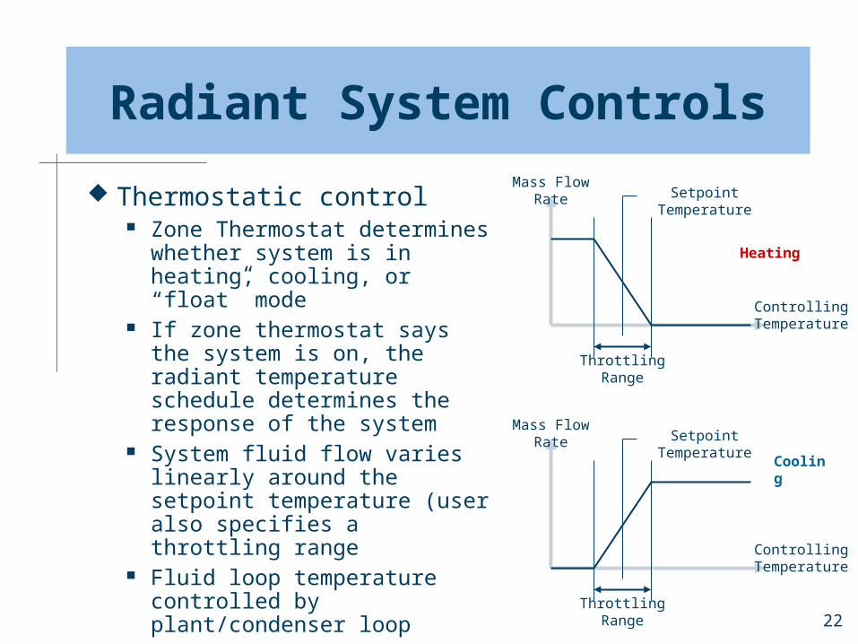
Thermostatic control Zone Thermostat
determines whether system is in heating, cooling, or “float” mode
If zone thermostat says the system is on, the radiant temperature schedule determines the response of the system
System fluid flow varies linearly around the setpoint temperature (user also specifies a throttling range
Fluid loop temperature controlled by plant/condenser loop
Mass Flow Rate
Controlling Temperature
Setpoint Temperature
Throttling Range
Mass Flow Rate
Controlling Temperature
Throttling Range
Setpoint Temperature
Heating
Cooling
23
Radiant System Controls (cont’d)
Control temperature In determining the system response, the
radiant control setpoint can be compared to a variety of other temperatures depending on the type of control one desires: Zone Mean Air Temperature Zone Mean Radiant Temperature Zone Operative Temperature (average of MAT and
MRT) Outside Air Dry-Bulb Temperature (low
temperature systems only) Outside Air Wet-Bulb Temperature (low
temperature systems only)
24
Radiant System Controls (cont’d)
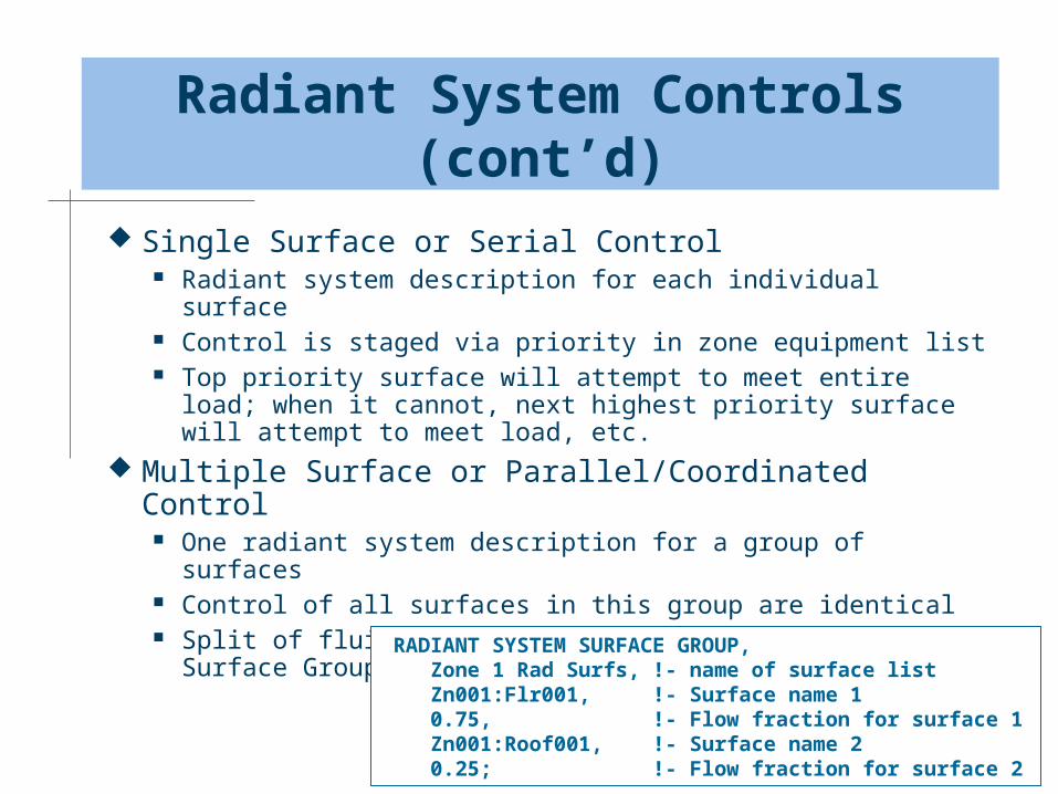
Single Surface or Serial Control Radiant system description for each individual surface Control is staged via priority in zone equipment list Top priority surface will attempt to meet entire load;
when it cannot, next highest priority surface will attempt to meet load, etc.
Multiple Surface or Parallel/Coordinated Control One radiant system description for a group of surfaces Control of all surfaces in this group are identical Split of fluid flow determined by Radiant System Surface
Group input RADIANT SYSTEM SURFACE GROUP, Zone 1 Rad Surfs, !- name of surface list Zn001:Flr001, !- Surface name 1 0.75, !- Flow fraction for surface 1 Zn001:Roof001, !- Surface name 2 0.25; !- Flow fraction for surface 2

25
Low Temperature Surface Input
IDF Example: CONSTRUCTION WITH INTERNAL SOURCE, Slab Floor with Radiant, !- Name 3, !- Source present after this layer in definition below 4, !- Temperature calculation requested after this layer 1, !- Dimensions for the CTF calculation (1- or 2-D) 0.1524, !- Tube Spacing {m} CONCRETE - DRIED SAND AND GRAVEL 4 IN, !- Outside Layer INS - EXPANDED EXT POLYSTYRENE R12 2 IN, !- Layer #2 GYP1, !- Layer #3 GYP2, !- Layer #4 FINISH FLOORING - TILE 1 / 16 IN; !- Layer #5
Based on the above input, the tubing (and thus the heat source or sink) would be applied between layers 3 and 4 in this construction
26
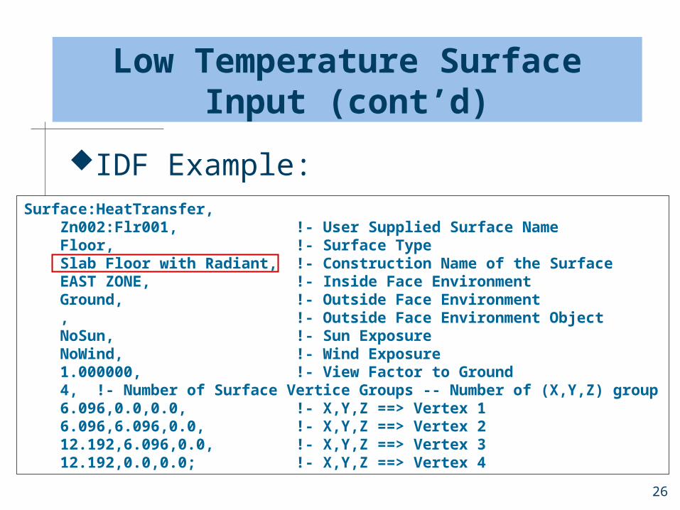
Low Temperature Surface Input (cont’d)
IDF Example:Surface:HeatTransfer, Zn002:Flr001, !- User Supplied Surface Name Floor, !- Surface Type Slab Floor with Radiant, !- Construction Name of the Surface EAST ZONE, !- Inside Face Environment Ground, !- Outside Face Environment , !- Outside Face Environment Object NoSun, !- Sun Exposure NoWind, !- Wind Exposure 1.000000, !- View Factor to Ground 4, !- Number of Surface Vertice Groups -- Number of (X,Y,Z) group 6.096,0.0,0.0, !- X,Y,Z ==> Vertex 1 6.096,6.096,0.0, !- X,Y,Z ==> Vertex 2 12.192,6.096,0.0, !- X,Y,Z ==> Vertex 3 12.192,0.0,0.0; !- X,Y,Z ==> Vertex 4
27
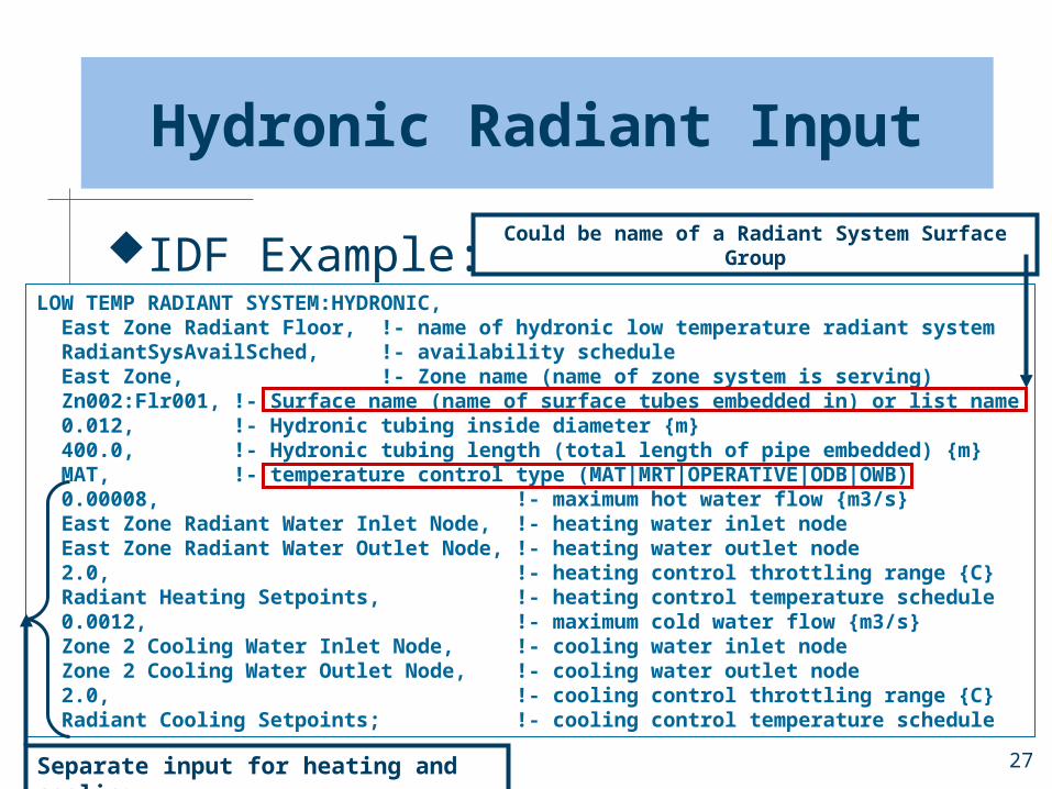
Hydronic Radiant Input
IDF Example:LOW TEMP RADIANT SYSTEM:HYDRONIC, East Zone Radiant Floor, !- name of hydronic low temperature radiant system RadiantSysAvailSched, !- availability schedule East Zone, !- Zone name (name of zone system is serving) Zn002:Flr001, !- Surface name (name of surface tubes embedded in) or list name 0.012, !- Hydronic tubing inside diameter {m} 400.0, !- Hydronic tubing length (total length of pipe embedded) {m} MAT, !- temperature control type (MAT|MRT|OPERATIVE|ODB|OWB) 0.00008, !- maximum hot water flow {m3/s} East Zone Radiant Water Inlet Node, !- heating water inlet node East Zone Radiant Water Outlet Node, !- heating water outlet node 2.0, !- heating control throttling range {C} Radiant Heating Setpoints, !- heating control temperature schedule 0.0012, !- maximum cold water flow {m3/s} Zone 2 Cooling Water Inlet Node, !- cooling water inlet node Zone 2 Cooling Water Outlet Node, !- cooling water outlet node 2.0, !- cooling control throttling range {C} Radiant Cooling Setpoints; !- cooling control temperature schedule
Separate input for heating and cooling
Could be name of a Radiant System Surface Group

28
Electric Low Temperature Radiant Heating Systems
IDF Example: LOW TEMP RADIANT SYSTEM:ELECTRIC, Zone 1 Elec Floor, !- name of electric low temperature radiant system RadPanelAvailSched, !- availability schedule NORTH ZONE, !- Zone name (name of zone system is serving) Zone 1 Rad Surfs, !- Surface name or Radiant System Surface Group name 10000, !- maximum electrical power to panel {W} MRT, !- temperature control type (MAT|MRT|Operative|ODB|OWB) 2.0, !- heating throttling range {C} Radiant Heating Setpoints; !- heating setpoint temperature schedule
Note: Input similar to hydronic radiant system except no fluid loop information and no cooling information

29
High Temperature Radiant Systems
IDF Example: HIGH TEMP RADIANT SYSTEM, Zone 1 Radiant Heater, !- name of high temperature radiant system RadiantPanelAvailSched, !- availability schedule NORTH ZONE, !- Zone name (name of zone system is serving) 10000, !- maximum power input {W} GAS, !- type of high temperature radiant heater (GAS|ELECTRIC) 0.85, !- combustion efficiency (ignore for electric radiant heaters) 0.75, !- fraction of input converted to radiant energy 0.00, !- fraction of input converted to latent energy 0.00, !- fraction of input that is lost (vented to outside environment) OPERATIVE, !- temperature control type (MAT|MRT|OPERATIVE) 2.0, !- heating throttling range {C} Radiant Heating Setpoints, !- heating setpoint temperature schedule 0.05, !- fraction of radiant energy incident on people Zn001:Flr001, !- surface to which radiant energy from heater is distributed 0.75, !- fraction of radiant energy from heater distributed to surface Zn001:Wall001, !- surface to which radiant energy from heater is distributed 0.25; !- fraction of radiant energy from heater distributed to surface
Energy has no effect on zone or any surface
User-defined output pattern, fraction must add to 1
Affects thermal comfort directly, then convected to zone air
30
Summary
Radiant systems use radiation as the primary mode of heat transfer to heat space occupants directly rather than indirectly by conditioning air
Low and high temperature radiant systems can be defined in EnergyPlus as zone equipment
Hydronic radiant systems are connected to a primary system loop much like a water coil