Embed Size (px)
Citation preview
Lecture 21Network Function
and s-domain AnalysisHung-yi Lee
Outline
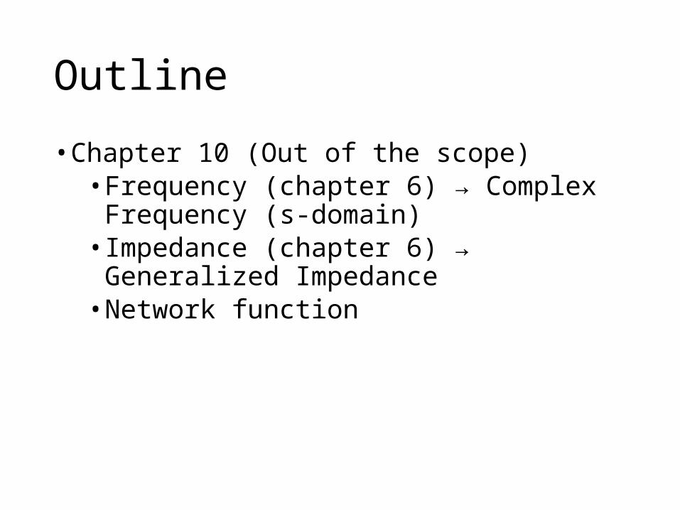
• Chapter 10 (Out of the scope)• Frequency (chapter 6) → Complex Frequency (s-
domain)• Impedance (chapter 6) → Generalized
Impedance• Network function
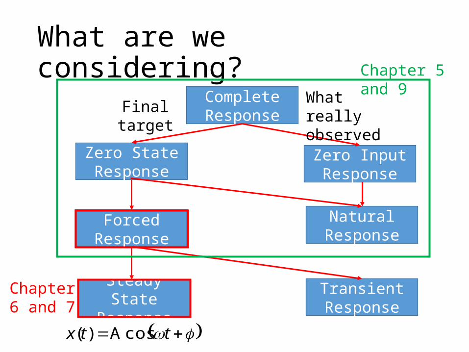
What are we considering?Complete Response
Natural Response
Forced Response
Zero State Response
Zero Input Response
Transient Response
Steady State Response
Final target What really observed
Chapter 5 and 9
Chapter 6 and 7
ttx cosA)(

What are we considering?Complete Response
Natural Response
Forced Response
Zero State Response
Zero Input Response
Transient Response
Steady State Response
Final target What really observed
Chapter 5 and 9
This lecture
ttx cosAe)( t

Complex Frequency

Complex FrequencyIn Chapter 6
Current or Voltage Sources Currents or Voltages in the circuit ttx cosA)( ttx cosA)(
In Chapter 10Current or Voltage Sources Currents or Voltages in the circuit
ttx cosAe)( t ttx coseA)( t
You can observe the results from differential equation.
The same frequencyDifferent magnitude and phase
Different magnitude and phase
The same frequency and exponential term
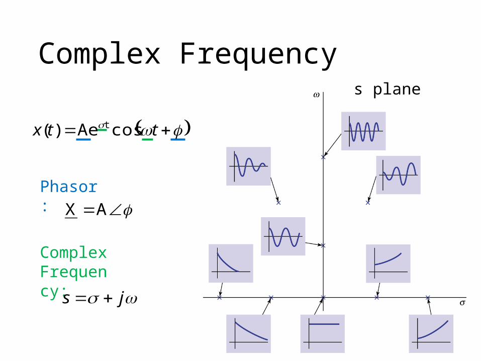
ttx cosAe)( t
Phasor:AX
Complex Frequency:
js
s plane
Complex Frequency

Generalized Impedance

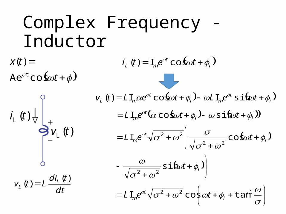
Complex Frequency - Inductor
)(L tv)(L ti
dt
tdiLtv L
L
)()(
imL tti cosI)(
imL tLtv sinI)(
90cosI im tL
imLI I
90LIVL im
Impedance of inductor
L90LI
90LI
I
VZ
L
L
L
j
im
im
For AC Analysis(Chapter 6)
Complex Frequency - Inductor
itmL teti cosI)(
itmi
tmL teLteLtv sinIcosI)(
iit
m tteL sincosI
122 tancosI i
tm teL
i
it
m
t
teL
sin
cosI
22
22
22)(L tv)(L ti
dt
tdiLtv L
L
)()(
t
tx
cosAe
)(t

Complex Frequency - Inductor
itmL teti cosI)(
1
22
tancos
I
i
tmL
t
eLtv
imLI I
122
L tanLIV im
Generalized Impedance of inductor
im
im
I
tanLI
I
VZ
122
L
L
L
122 tanL
2222
22L
j L j Ls
js

Generalized Impedance
• Generalized Impedance (Table 10.1)
Element
Resistor
Inductor Capacitor
Impedance GeneralizedImpedance
R RLj sL
Cj/1 C/1 s
Special case: js
The circuit analysis for DC circuits can be used.
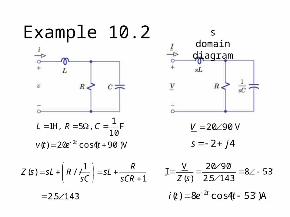
Example 10.2
V)904cos(20)(
F10
1 ,5 H,1
2
tetv
CRL
t
V9020 V
42 js
1
1//)(
sCR
RsL
sCRsLsZ
1435.2
5381435.2
9020
)(
VI
sZ
A)534cos(8)( 2 teti t
s domain diagram
Network Function

Network Function / Transfer Function• Given the phasors of two branch variables, the ratio of the
two phasors is the network function/transfer function
X
Ys H
The ratio depends on complex frequencyComplex number
XsY H outputY :inputX :
phasors of current or voltage

Network Function / Transfer Function
X
Ys H Impedance and admittance are
special cases for network function
I
VZ sImpedance:
Admittance: V
I1Y
sZs
I
V
• Network Function/Transfer Function is not new idea

Network Function / Transfer Function
1
2VH
Vs
I
VH s
1
2IH
Is
V
IH s
X
Ys H
Current or voltage
Current or voltage
In general, network function can have four meaning
Voltage Gain
Current Gain
“Impedance”
“Admittance”

Example 10.5
s
L
V
IsH )(1
sV
LV RV
CV
CILI
sCRsLIV Ls
1
sC
1
RsL
11
1H
21
sRCLCs
sC
sCRsLV
Is
s
L
Polynomial of s
Polynomial of s

Example 10.5
sV
VsH
L
2 )(
sV
LV RV
CV
CILI
sCRsL
sL1
sC
1
RsL
Polynomial of s
Polynomial of s12
2
sRCLCs
LCs

Network Function / Transfer Function
XsY H |||H||| XsY XH sY
|H(s)| is complex frequency dependent
js
Output will be very large when
74 j
ttx 7cosAe)( t4
gain dc theis )0(H dc represents 0s

Example 10.5 – Check your results by DC Gain
sV
LV RV
CV
CILI
sC
1
RsL
12
sRCLCs
sC
12
2
sRCLCs
LCs
00H1
00H2
s
L
V
IsH )(1
sV
VsH
L
2 )(
For DCCapacitor = open circuit
Inductor = short circuit

Example 10.5 – Check your results by Units
sV
LV RV
CV
CILI
sC
1
RsL
12
sRCLCs
sC
12
2
sRCLCs
LCss
L
V
IsH )(1
sV
VsH
L
2 )(
V
AtF:C
A
VH:L t
A
V:R ?:s
t
1
A
V
V
At
t
1
V
At
A
Vt
2
t
1V
AtA
V
t
1
V
V
V
At
A
Vt
2
t
1
V
At
A
Vt
2
t
1V
AtA
V
t
1

Zeros/Poles

Poles/Zeros
• General form of network function
011
1
011
1)(asasasa
bsbsbsbsH
nn
nn
mm
mm
If z is a zero, H(z) is zero.
If p is a pole, H(s) is infinite.
The “zeros” is the root of N(s).
The “poles” is the root of D(s).
sDsN
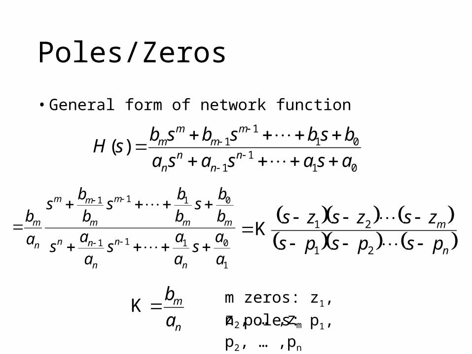
Poles/Zeros
• General form of network function
1
0111
0111
aa
saa
saa
s
bb
sbb
sbb
s
a
b
n
n
n
nn
mm
m
m
mm
n
m
n
m
pspsps
zszszs
21
21K
n
m
a
bK
011
1
011
1)(asasasa
bsbsbsbsH
nn
nn
mm
mm
m zeros: z1, z2, … ,zm
n poles: p1, p2, … ,pn

Example 10.8
400403632
164165)(
22
234
ssss
ssssH Find its zeros and poles
234 16416 sss 164162 ssss
4300 zszsss
Zeros: z1=0, z2=0, z3=-8+j10, z4=-8-j10
3232 1 ps
6,36 322 jpps
2040040 542 ppss
Poles: p1=-32, p2=j6, p3=-6j, p4=-20, p5=-20
Numerator: Denominator:
z3 and z4 are the two roots of s2+16s+164

Example 10.8
400403632
164165)(
22
234
ssss
ssssH
We can read the characteristics of the network function from this diagram
Pole and Zero Diagram
Find its zeros and poles
Zero (O), pole (X)
Zeros: z1=0, z2=0, z3=-8+j10, z4=-8-j10
Poles: p1=-32, p2=j6, p3=-6j, p4=-20, p5=-20
For example, stability of network
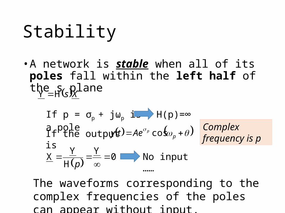
Stability
• A network is stable when all of its poles fall within the left half of the s plane
XsHY
If p = σp + jωp is a pole H(p)=∞
The waveforms corresponding to the complex frequencies of the poles can appear without input.
ppAety cos
Complex frequency is p
No input …… 0Y
H
YX
p
If the output is

Stability
• A network is stable when all of its poles fall within the left half of the s plane
The poles are at the right plane.
Appear automatically
Unstable
The poles are at the left plane.
Stable
Appear automatically

Stability
• A network is stable when all of its poles fall within the left half of the s plane
The poles are on the jω axis.
σp = 0
Appear automatically
Marginally stable
oscillator

Thank you!

Acknowledgement
• 感謝 趙祐毅 (b02)• 在上課時指出投影片中的錯誤

Appendix

What is Network/Transfer Function considered?
Input
Output
Natural Response
Forced Response
NetworkFunction H(s)
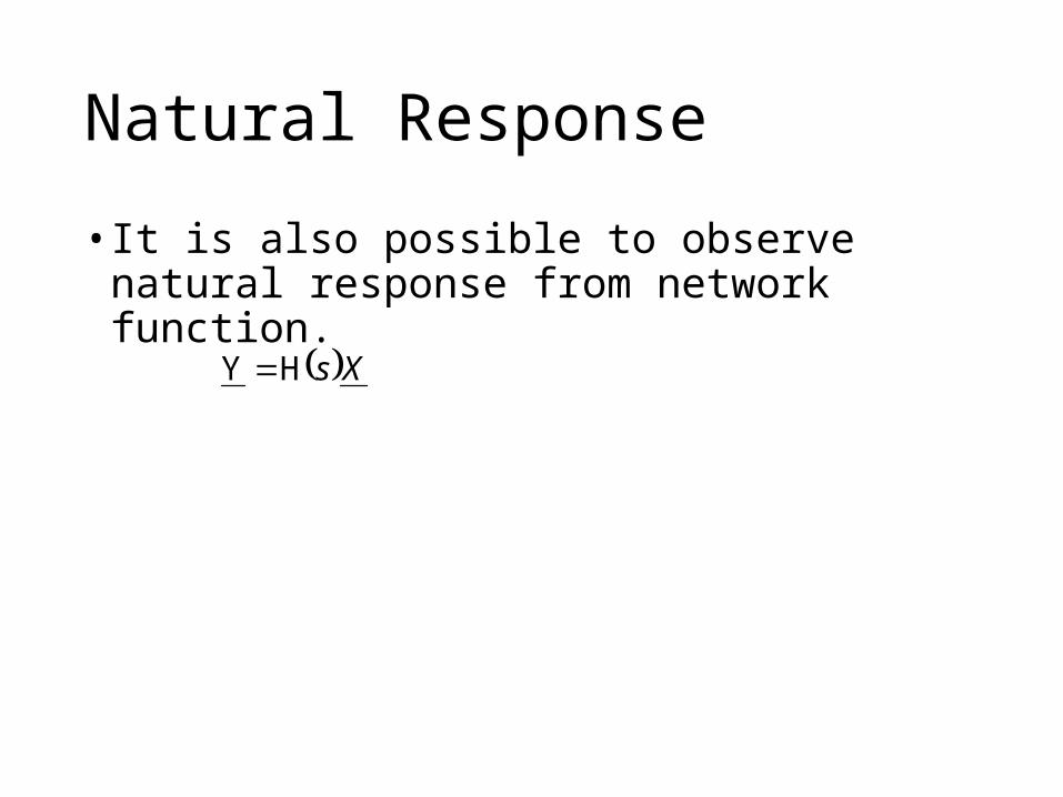
Natural Response
• It is also possible to observe natural response from network function.
XsHY
Differential Equation
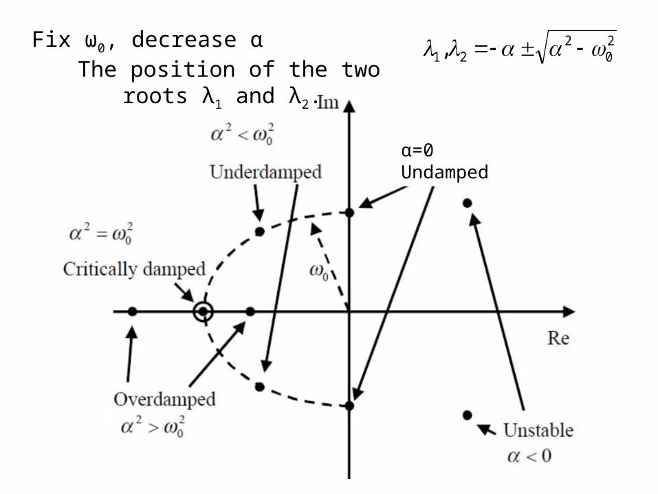
α=0Undamped
Fix ω0, decrease αThe position of the two roots λ1 and λ2.
20
221,
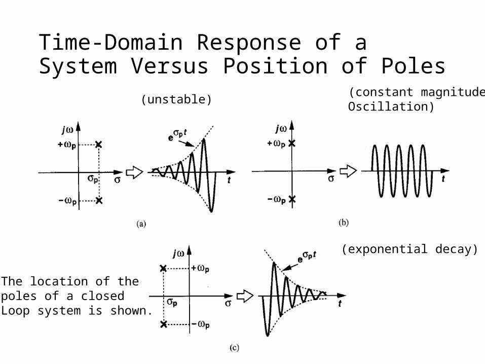
Time-Domain Response of a System Versus Position of Poles
(unstable) (constant magnitudeOscillation)
(exponential decay)
The location of the poles of a closedLoop system is shown.

Cancellation
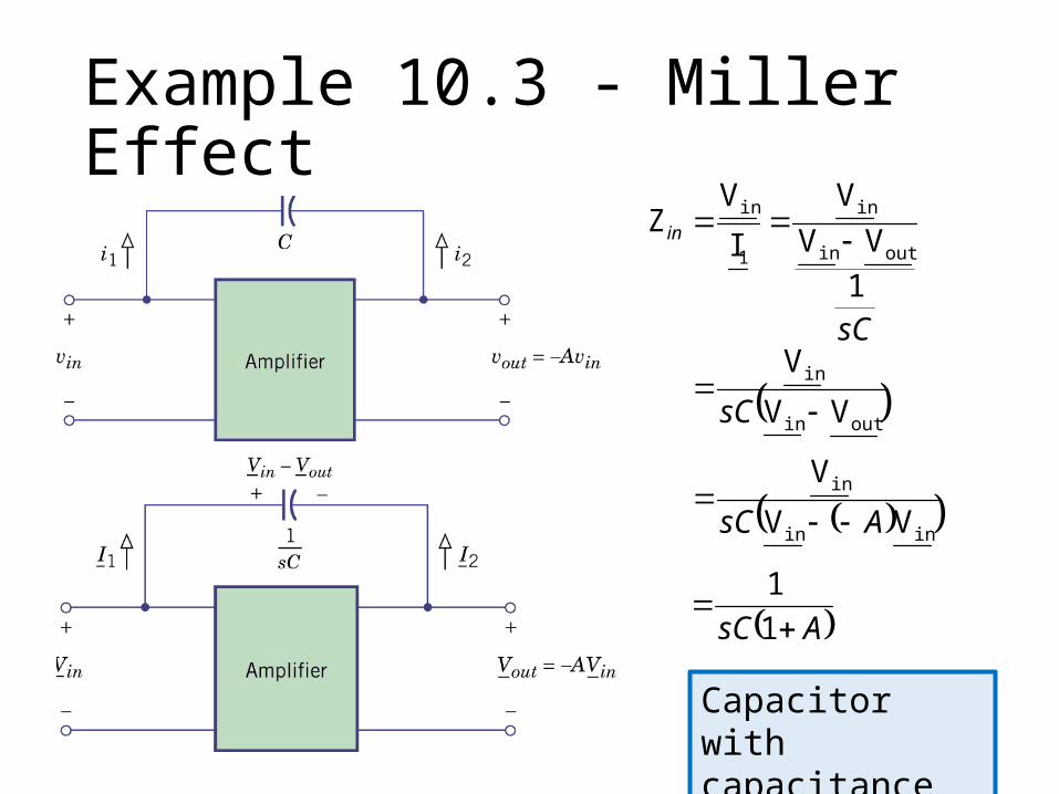
Example 10.3 - Miller Effect
sC
in
1
VV
V
I
VZ
outin
in
1
in
outin
in
VV
V
sC
inin
in
VV
V
AsC
AsC
1
1
Capacitor with capacitance C(1+A)

Example 10.3 - Miller Effect
sC
out
1
VV
V
I
VZ
inout
out
2
out
inout
out
VV
V
sC
inin
in
VV
V
AsC
A
AsC
A
1
AsC
11
1
Capacitor with capacitance
AC
11
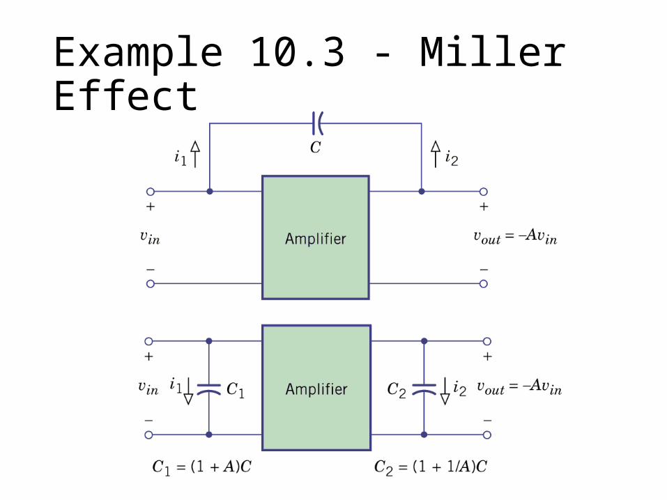
Example 10.3 - Miller Effect