Embed Size (px)
Citation preview
Lecture 22
Dispersion and Prisms Total internal Reflection Flat mirrors Convex and Concave
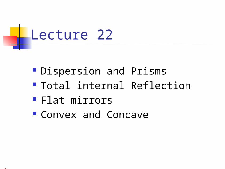
Fig. 22-24, p.741
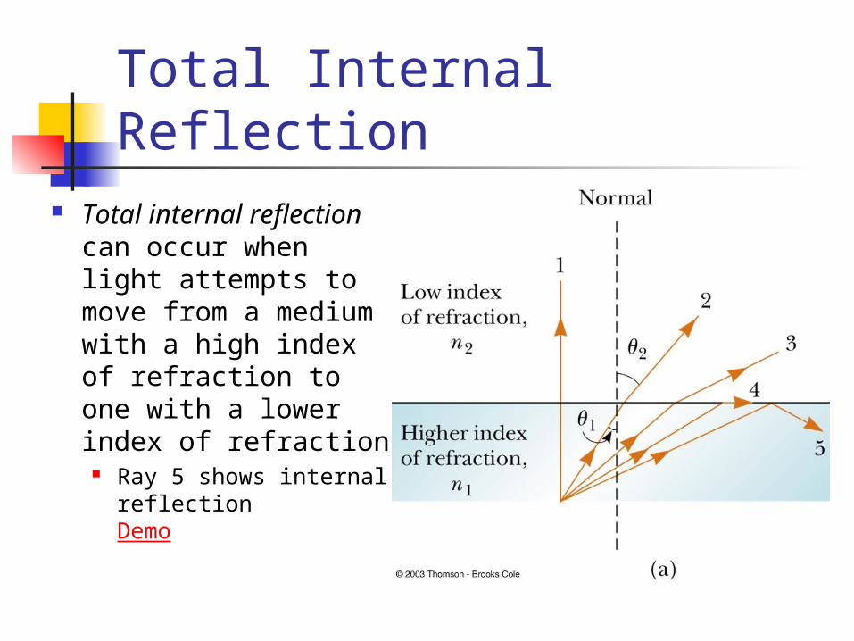
Total Internal Reflection Total internal
reflection can occur when light attempts to move from a medium with a high index of refraction to one with a lower index of refraction
Ray 5 shows internal reflectionDemo
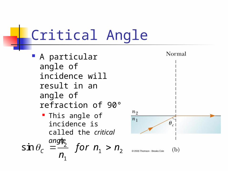
Critical Angle A particular angle
of incidence will result in an angle of refraction of 90° This angle of
incidence is called the critical angle
21 2
1
sin C
nfor n n
n
Critical Angle, cont For angles of incidence greater than the
critical angle, the beam is entirely reflected at the boundary This ray obeys the Law of Reflection at the
boundary Total internal reflection occurs only
when light attempts to move from a medium of higher index of refraction to a medium of lower index of refraction
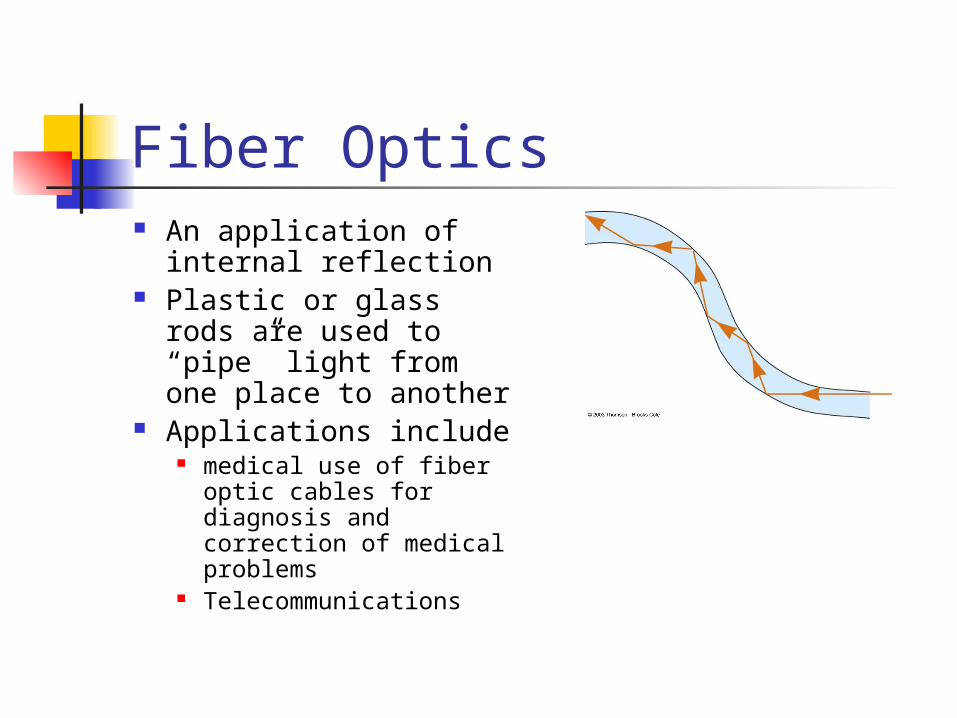
Fiber Optics An application of
internal reflection Plastic or glass rods
are used to “pipe” light from one place to another
Applications include medical use of fiber
optic cables for diagnosis and correction of medical problems
Telecommunications
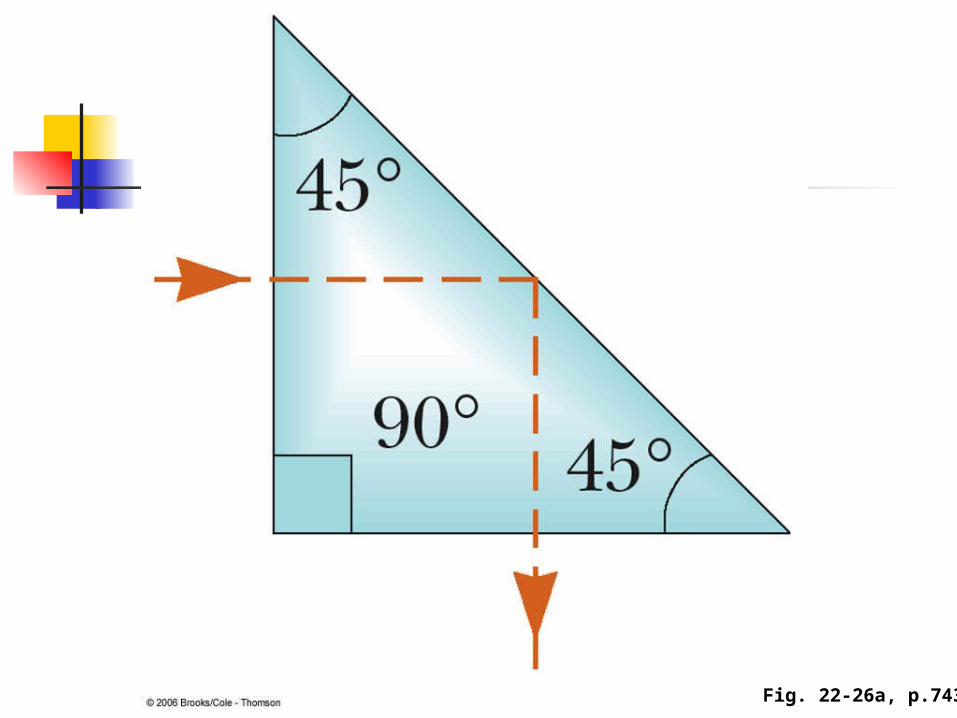
Fig. 22-26a, p.743
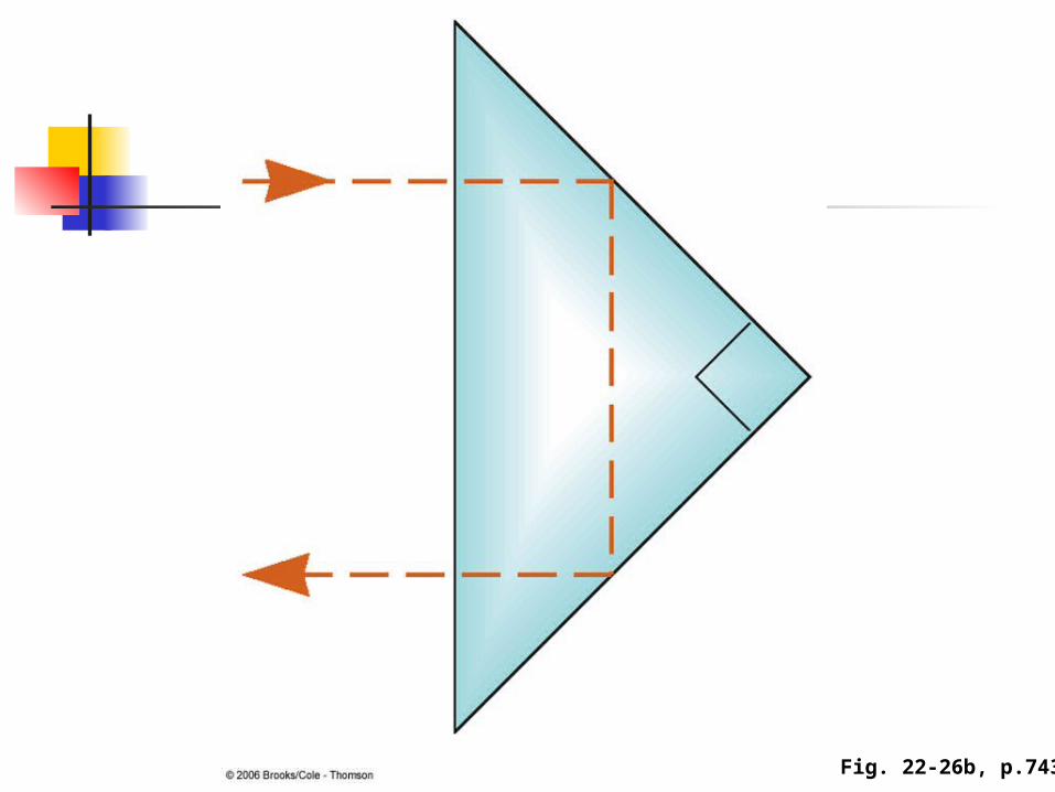
Fig. 22-26b, p.743
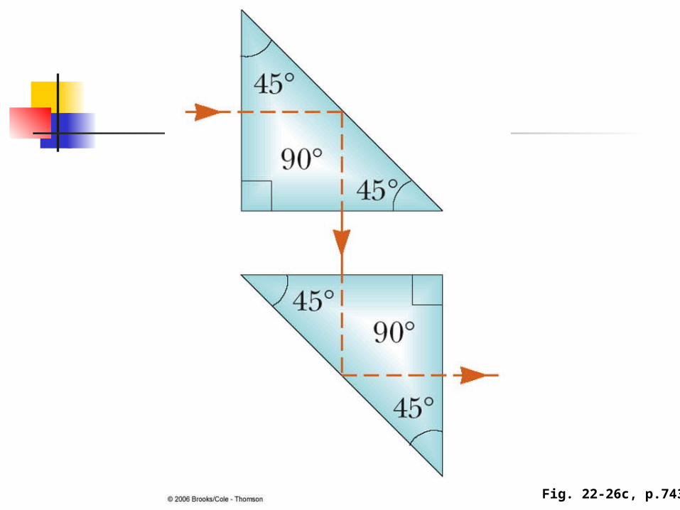
Fig. 22-26c, p.743
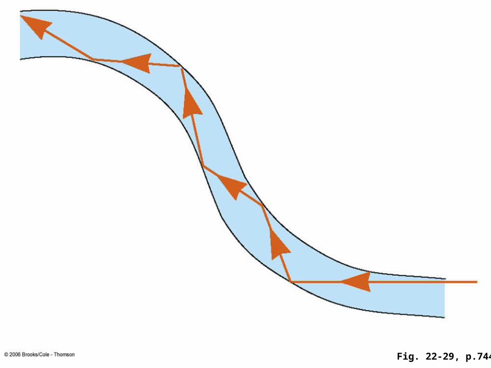
Fig. 22-29, p.744
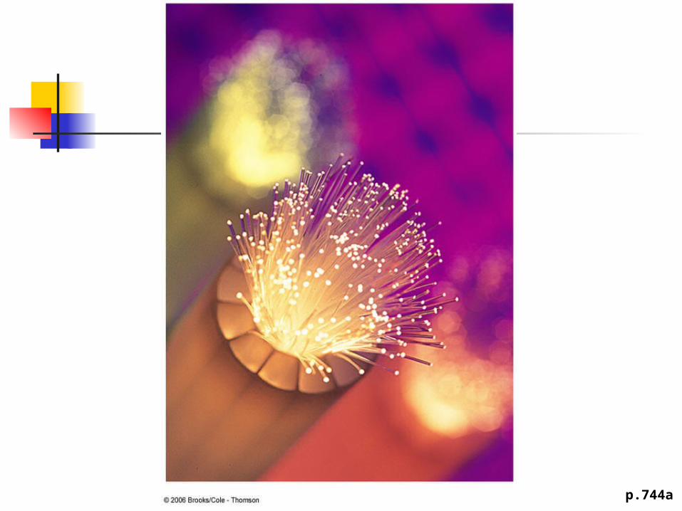
p.744a
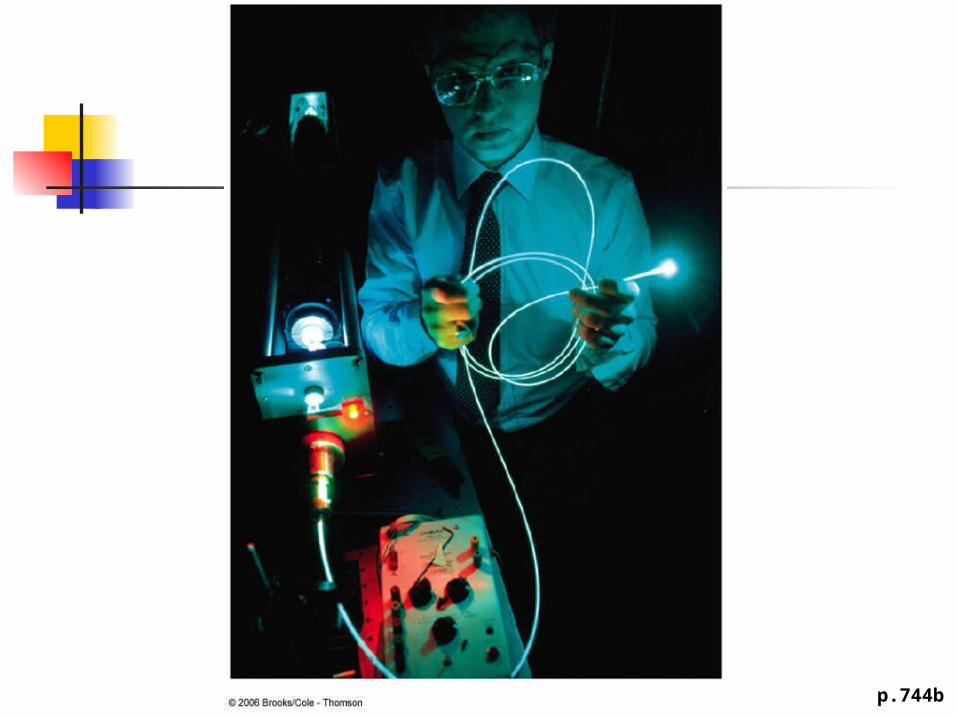
p.744b
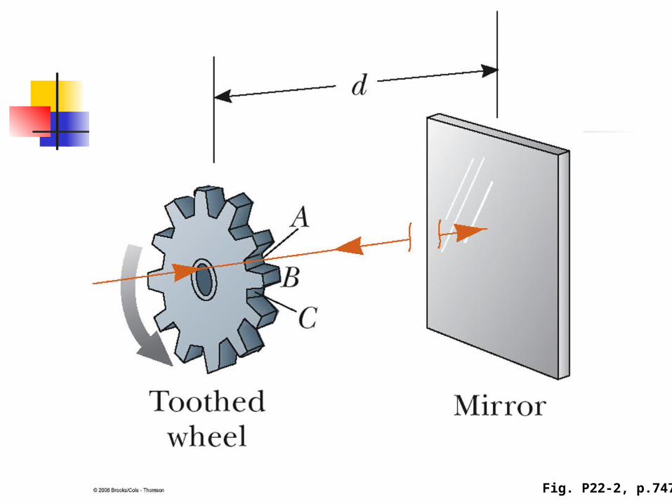
Fig. P22-2, p.747
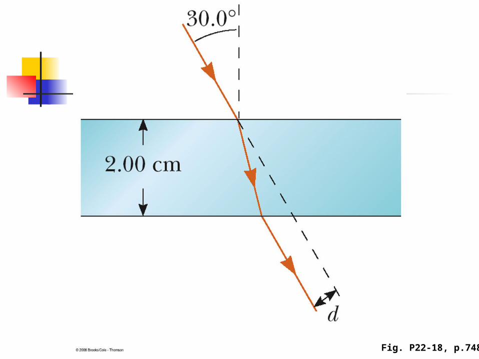
Fig. P22-18, p.748
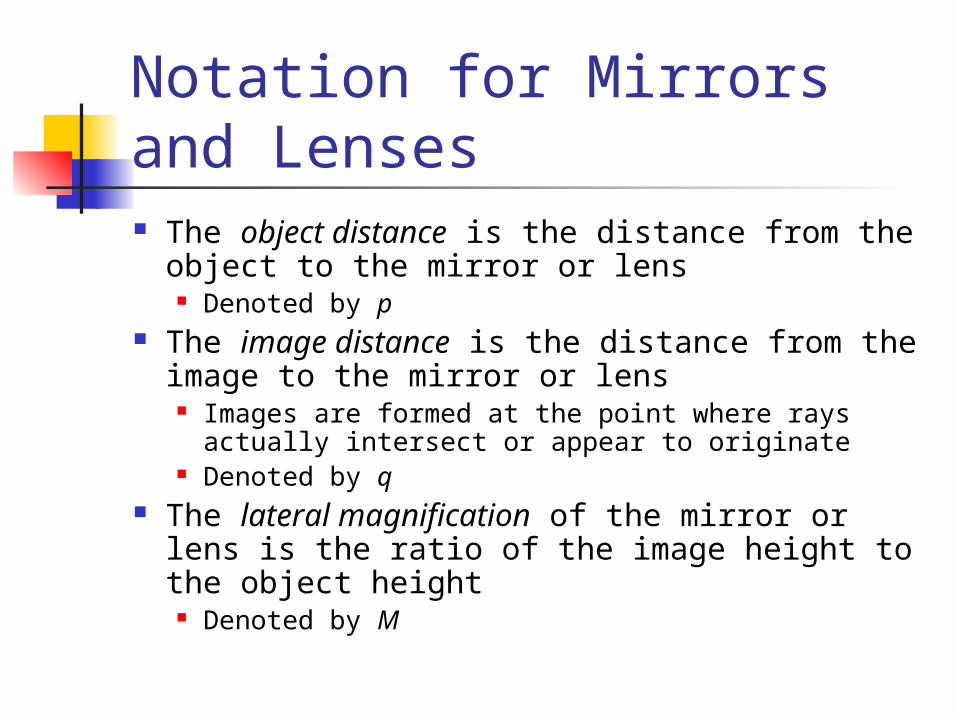
Notation for Mirrors and Lenses The object distance is the distance from the
object to the mirror or lens Denoted by p
The image distance is the distance from the image to the mirror or lens
Images are formed at the point where rays actually intersect or appear to originate
Denoted by q The lateral magnification of the mirror or lens
is the ratio of the image height to the object height
Denoted by M
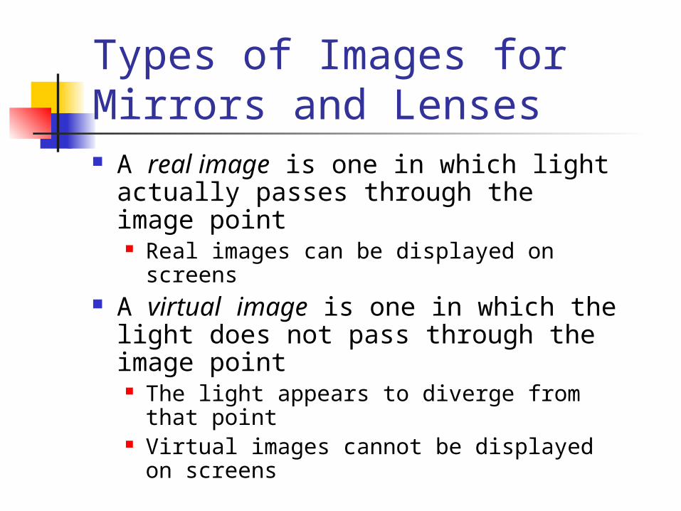
Types of Images for Mirrors and Lenses A real image is one in which light
actually passes through the image point Real images can be displayed on screens
A virtual image is one in which the light does not pass through the image point The light appears to diverge from that
point Virtual images cannot be displayed on
screens
More About Images To find where an image is formed,
it is always necessary to follow at least two rays of light as they reflect from the mirror
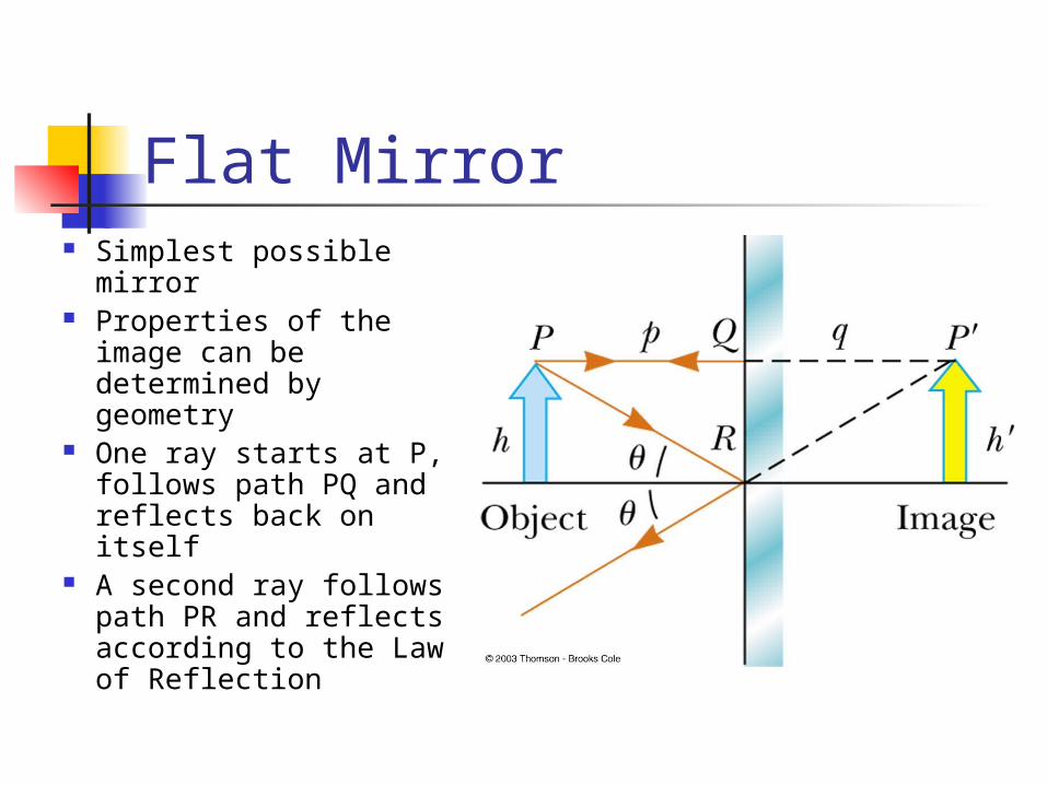
Flat Mirror Simplest possible
mirror Properties of the image
can be determined by geometry
One ray starts at P, follows path PQ and reflects back on itself
A second ray follows path PR and reflects according to the Law of Reflection
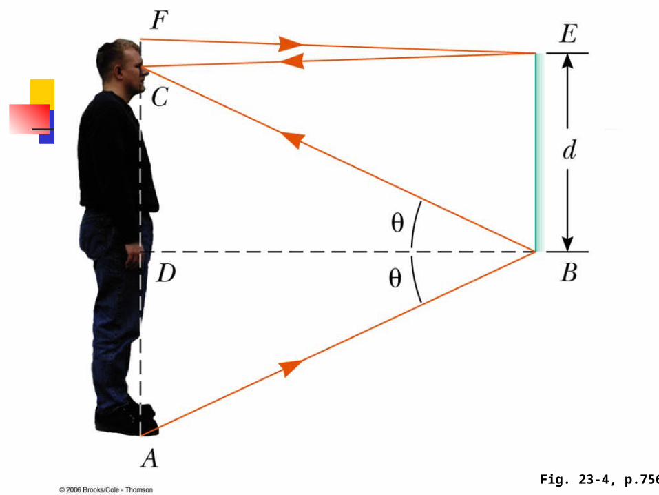
Fig. 23-4, p.756
Properties of the Image Formed by a Flat Mirror The image is as far behind the mirror as the
object is in front q = p
The image is unmagnified The image height is the same as the object height
h’ = h and M = 1 The image is virtual The image is upright
It has the same orientation as the object There is an apparent left-right reversal in the
image
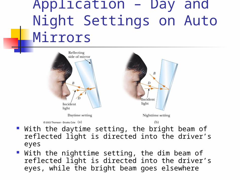
Application – Day and Night Settings on Auto Mirrors
With the daytime setting, the bright beam of reflected light is directed into the driver’s eyes
With the nighttime setting, the dim beam of reflected light is directed into the driver’s eyes, while the bright beam goes elsewhere
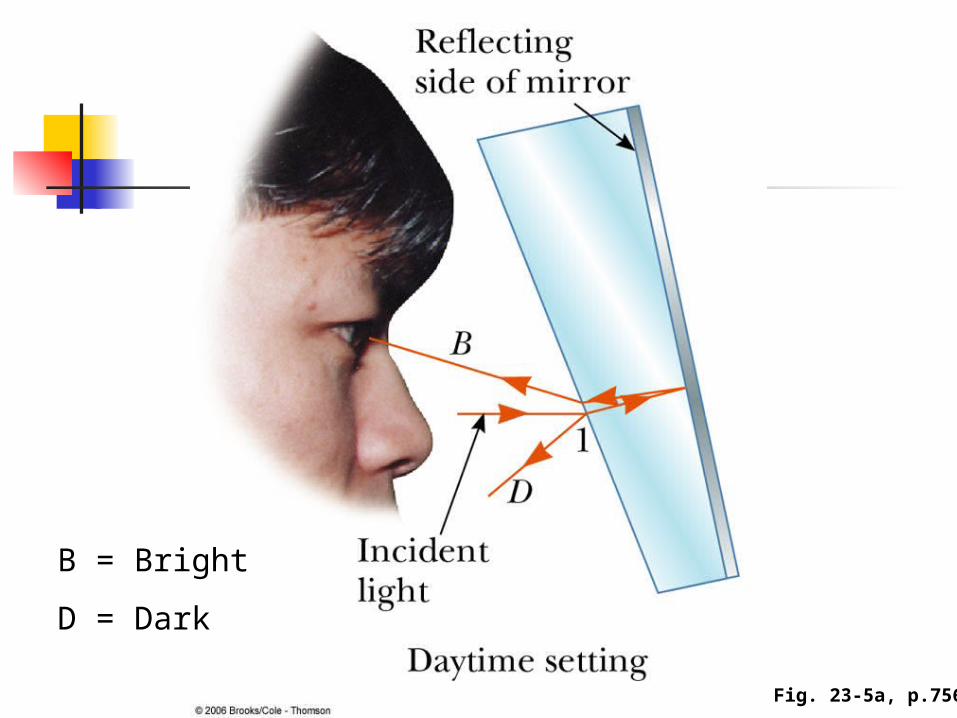
Fig. 23-5a, p.756
B = Bright
D = Dark
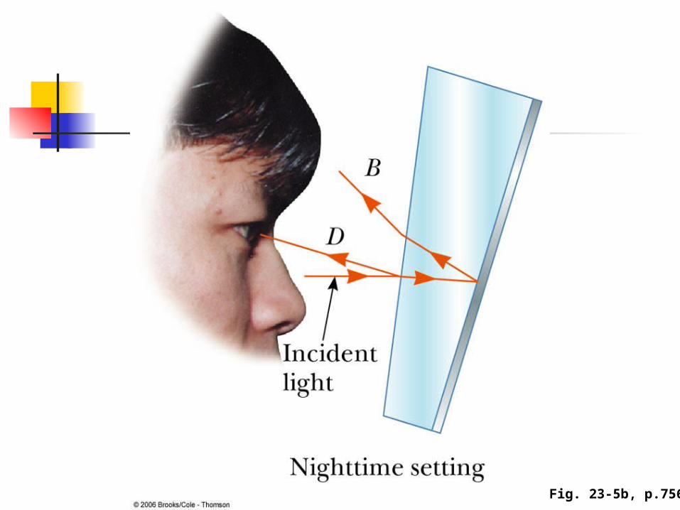
Fig. 23-5b, p.756
Spherical Mirrors A spherical mirror has the shape of a
segment of a sphere A concave spherical mirror has the
silvered surface of the mirror on the inner, or concave, side of the curve
A convex spherical mirror has the silvered surface of the mirror on the outer, or convex, side of the curve
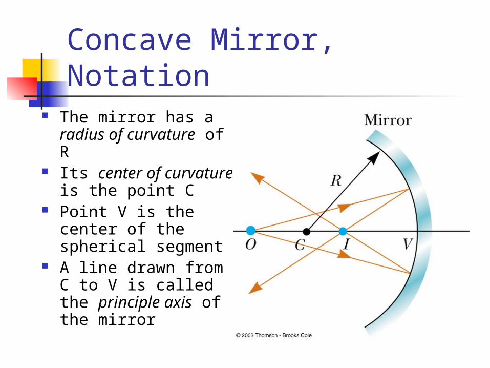
Concave Mirror, Notation The mirror has a
radius of curvature of R
Its center of curvature is the point C
Point V is the center of the spherical segment
A line drawn from C to V is called the principle axis of the mirror
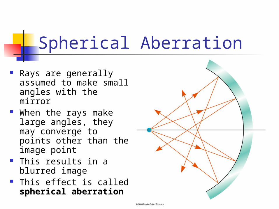
Spherical Aberration
Rays are generally assumed to make small angles with the mirror
When the rays make large angles, they may converge to points other than the image point
This results in a blurred image
This effect is called spherical aberration
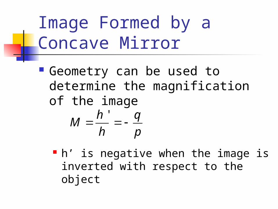
Image Formed by a Concave Mirror Geometry can be used to
determine the magnification of the image
h’ is negative when the image is inverted with respect to the object
'h qM
h p