Embed Size (px)
Citation preview

7/28/2019 Lecture 2ASASA
http://slidepdf.com/reader/full/lecture-2asasa 1/41
16-1
Engineering Drawings and Symbols
© 2011 Cengage Learning Engineering. All Rights Reserved.

7/28/2019 Lecture 2ASASA
http://slidepdf.com/reader/full/lecture-2asasa 2/41
Chapter 16: Sections 1 – 5
Material to be Covered

7/28/2019 Lecture 2ASASA
http://slidepdf.com/reader/full/lecture-2asasa 3/41
16-3
Outline
In th is chapter we wi l l
• Discuss the need for conventional
engineering symbols and drawings
• Show how vital information for an object is
communicated to others using
Orthographic views
Isometric views Sectional views
© 2011 Cengage Learning Engineering. All Rights Reserved.

7/28/2019 Lecture 2ASASA
http://slidepdf.com/reader/full/lecture-2asasa 4/41
16-4
Outline
In th is chapter we wi l l
• Introduce basic rules of an engineering
drawing
Showing dimensions
Specifying material size
Indicating finished surfaces
• Show some common symbols used in civil,electrical, and mechanical engineering
© 2011 Cengage Learning Engineering. All Rights Reserved.

7/28/2019 Lecture 2ASASA
http://slidepdf.com/reader/full/lecture-2asasa 5/41
16-5
Objectives
The object ives of th is chapter are to
• Introduce engineering graphical
communication principles
• To discuss why engineering drawings are
important
© 2011 Cengage Learning Engineering. All Rights Reserved.

7/28/2019 Lecture 2ASASA
http://slidepdf.com/reader/full/lecture-2asasa 6/41
16-6
Importance of Engineering Drawing
• “a picture is worth a thousand words”
• In engineering, a good drawing is worth
even more than a thousand words
© 2011 Cengage Learning Engineering. All Rights Reserved.

7/28/2019 Lecture 2ASASA
http://slidepdf.com/reader/full/lecture-2asasa 7/41
16-7
Importance of Engineering Drawing
• Engineering drawings are important in
conveying useful information to other
engineers and machinists
Allow the readers to visualize what theproposed product would look like
Provide information on dimensions and
material used to make the proposed product
Provide views from the top, the side, and thefront
© 2011 Cengage Learning Engineering. All Rights Reserved.

7/28/2019 Lecture 2ASASA
http://slidepdf.com/reader/full/lecture-2asasa 8/41
16-8
Orthographic Views
Orthographic views show what an object’s
projection looks like
when seen from the top,
the front, or the side
© 2011 Cengage Learning Engineering. All Rights Reserved.

7/28/2019 Lecture 2ASASA
http://slidepdf.com/reader/full/lecture-2asasa 9/41
16-9
Orthographic Views
Relative locations of the top, bottom, front, back,right-side, and left-side view
© 2011 Cengage Learning Engineering. All Rights Reserved.

7/28/2019 Lecture 2ASASA
http://slidepdf.com/reader/full/lecture-2asasa 10/41
16-10
Orthographic Views
• Views needed to fully describe an object Top view
Front view
Right-side view
© 2011 Cengage Learning Engineering. All Rights Reserved.

7/28/2019 Lecture 2ASASA
http://slidepdf.com/reader/full/lecture-2asasa 11/41
16-11
Orthographic Views
• Three types of lines used in orthographical
views
Sol id l ines represent
• Visible edges of the planes• Intersection of two planes
Hidden or dashed l ines represent
• An edge of a plane
• Extreme limits of a cylindrical hole inside theobject
• Intersection of two planes not visible from the
direction you are looking
© 2011 Cengage Learning Engineering. All Rights Reserved.
7/28/2019 Lecture 2ASASA
http://slidepdf.com/reader/full/lecture-2asasa 12/41
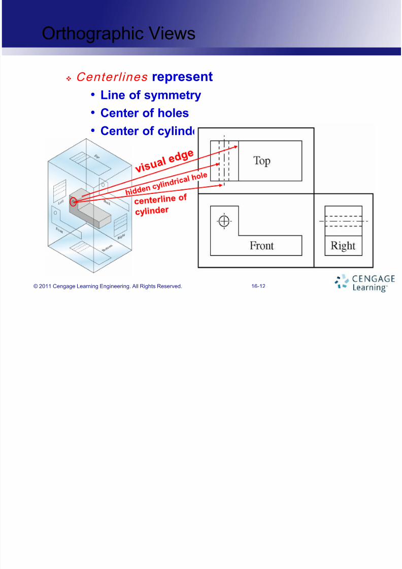
Centerl ines represent
• Line of symmetry
• Center of holes
• Center of cylinders
16-12
Orthographic Views
© 2011 Cengage Learning Engineering. All Rights Reserved.

7/28/2019 Lecture 2ASASA
http://slidepdf.com/reader/full/lecture-2asasa 13/41
16-13
Orthographic Views
Some objects can be fully described with one viewor two views
Washer can be described
by 1 view and thickness
This object can be
described by 2 views:
front and top
© 2011 Cengage Learning Engineering. All Rights Reserved.
7/28/2019 Lecture 2ASASA
http://slidepdf.com/reader/full/lecture-2asasa 14/41
16-14
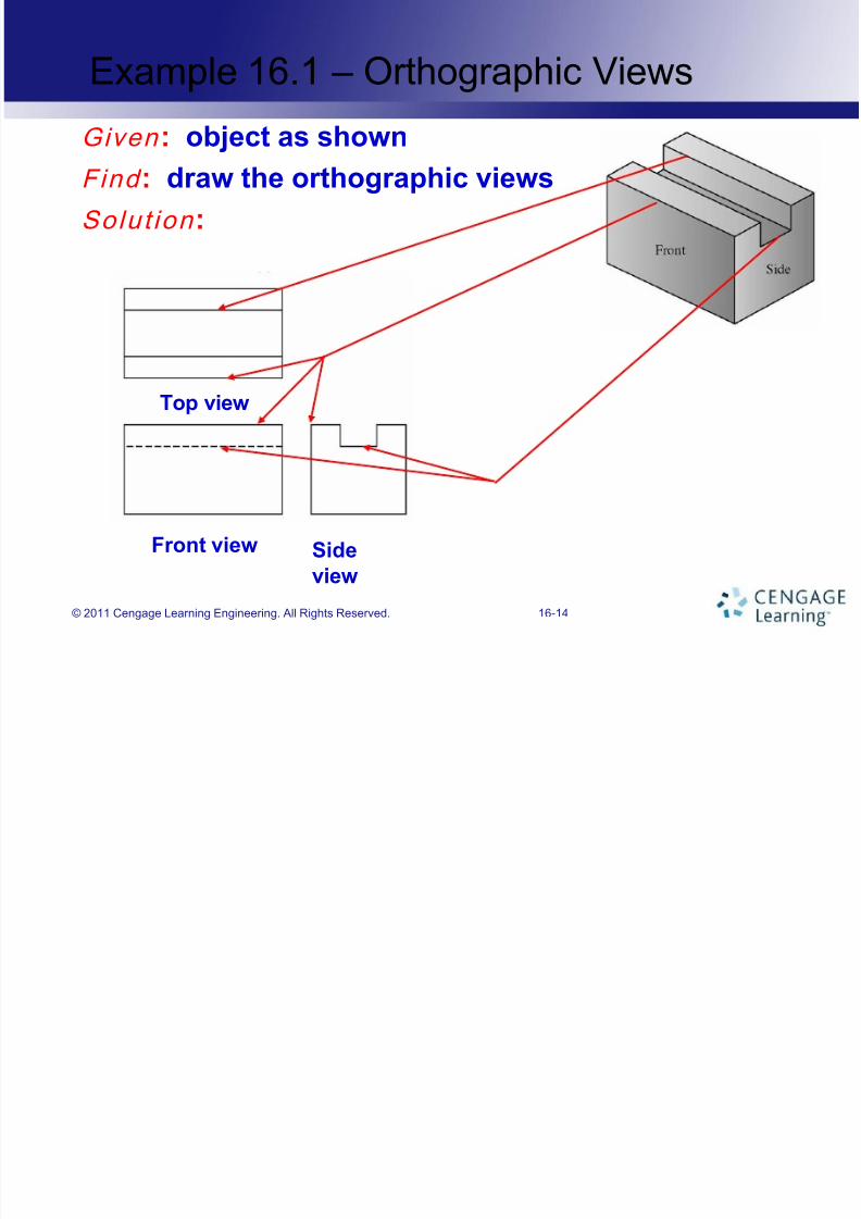
Example 16.1 – Orthographic Views
Given : object as shown
Find : draw the orthographic views
Solut ion :
Front view
Top view
Side
view
© 2011 Cengage Learning Engineering. All Rights Reserved.

7/28/2019 Lecture 2ASASA
http://slidepdf.com/reader/full/lecture-2asasa 15/41
16-15
Dimensioning and Tolerancing
• American National Standard Institute
(ANSI) sets the standards for the
dimensioning and tolerancing practice for
engineering drawings
• Every engineering drawing must include
Dimensions
Tolerances Materials from which products will be made
Finished surfaces marked
Other notes such as part numbers
© 2011 Cengage Learning Engineering. All Rights Reserved.

7/28/2019 Lecture 2ASASA
http://slidepdf.com/reader/full/lecture-2asasa 16/41
16-16
Dimensioning
• Two concepts when specifying dimensions Size
Location
• Basic dimensioning practice Dimension l ines
• Provide information on the size of the object
Extension l ines
• Lines that extend from the points to which thedimension or location is to be specified
• Lines are drawn parallel to each other withdimension line placed between them
© 2011 Cengage Learning Engineering. All Rights Reserved.

7/28/2019 Lecture 2ASASA
http://slidepdf.com/reader/full/lecture-2asasa 17/41
16-17
Dimensioning
Leaders
• Arrows that point to a circle or a fillet for thepurpose of specifying their sizes
Fil let
• Rounded edges of an object• Size, radius of roundness must be specified
Inform ation box contains
• Name of person who prepared the drawing
•Title of the drawing
• Date
• Scale
• Sheet number and drawing number
© 2011 Cengage Learning Engineering. All Rights Reserved.

7/28/2019 Lecture 2ASASA
http://slidepdf.com/reader/full/lecture-2asasa 18/41
16-18
Dimensioning
dimension line
leader
centerline
extension line
Basics of dimensioning practice
© 2011 Cengage Learning Engineering. All Rights Reserved.

7/28/2019 Lecture 2ASASA
http://slidepdf.com/reader/full/lecture-2asasa 19/41
16-19
1”
Side
viewFront view
Top view
Example 16.2 – Dimensioning
Given : an object and its dimensions are shown belowFind : show dimensions in the orthographic views
Solut ion :
Orthographic views
© 2011 Cengage Learning Engineering. All Rights Reserved.

7/28/2019 Lecture 2ASASA
http://slidepdf.com/reader/full/lecture-2asasa 20/41
16-20
Tolerancing
• Engineered products generally consist of
many parts
Would everything fit correctly if the actual
dimension of machine part is off from thespecified value?
• Must specify a tolerance on your drawing
regarding the machine part dimension For example, 2.50 cm +/- 0.01 cm
© 2011 Cengage Learning Engineering. All Rights Reserved.

7/28/2019 Lecture 2ASASA
http://slidepdf.com/reader/full/lecture-2asasa 21/41
16-21
Isometric View
• Isometr ic drawing shows the 3-dimensions
of an object in a single view
Use to visualize objects that are difficult to
visualize in their orthographic views
• Also called technical i l lustrat ions
• Used to show parts or products in parts
manuals, repair manuals, and productcatalogs
© 2011 Cengage Learning Engineering. All Rights Reserved.

7/28/2019 Lecture 2ASASA
http://slidepdf.com/reader/full/lecture-2asasa 22/41
16-22
Isometric Drawings – Procedures
We will use the object shown to illustrate thesteps of isometric drawings
Step 1
Draw width, height, and depth axes
Step 2
Measure and draw total width, height, and
depth of object
© 2011 Cengage Learning Engineering. All Rights Reserved.
7/28/2019 Lecture 2ASASA
http://slidepdf.com/reader/full/lecture-2asasa 23/41
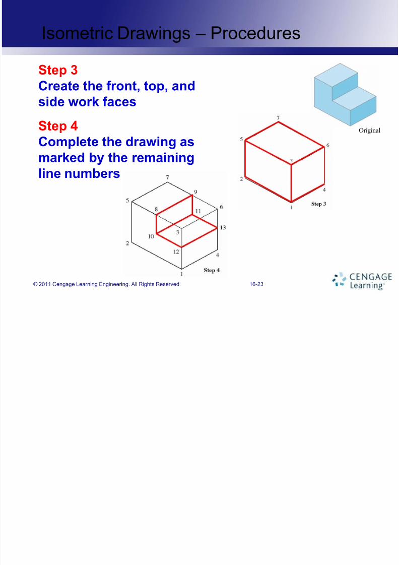
16-23
Isometric Drawings – Procedures
Step 3Create the front, top, and
side work faces
Step 4
Complete the drawing asmarked by the remaining
line numbers
Original
© 2011 Cengage Learning Engineering. All Rights Reserved.

7/28/2019 Lecture 2ASASA
http://slidepdf.com/reader/full/lecture-2asasa 24/41
16-24
Step 5
Isometric Drawings – Procedures
Step 5Erase unnecessary lines to
yield final drawing
Original
© 2011 Cengage Learning Engineering. All Rights Reserved.

7/28/2019 Lecture 2ASASA
http://slidepdf.com/reader/full/lecture-2asasa 25/41
16-25
Example 16.3 – Isometric Drawings
Given : object as shownFind : draw isometric view of object
Solut ion :
Step 1
Draw width, height, and depth axes
© 2011 Cengage Learning Engineering. All Rights Reserved.

7/28/2019 Lecture 2ASASA
http://slidepdf.com/reader/full/lecture-2asasa 26/41
16-26
Example 16.3 – Isometric Drawings
Step 2Measure and draw total width,
height, and depth of object
Step 3
Create the front, top, and
side work faces
Original
© 2011 Cengage Learning Engineering. All Rights Reserved.

7/28/2019 Lecture 2ASASA
http://slidepdf.com/reader/full/lecture-2asasa 27/41
16-27
Example 16.3 – Isometric Drawings
Step 4Complete the drawing
Step 5
Erase unnecessary lines
Original
© 2011 Cengage Learning Engineering. All Rights Reserved.

7/28/2019 Lecture 2ASASA
http://slidepdf.com/reader/full/lecture-2asasa 28/41
16-28
Sectional Views
• Sectional views are used when objects
have complex interiors
Reveal the inside of the object
Created by making an imaginary cut throughthe object
The direction of the sight is marked using
directional arrows
© 2011 Cengage Learning Engineering. All Rights Reserved.

7/28/2019 Lecture 2ASASA
http://slidepdf.com/reader/full/lecture-2asasa 29/41
16-29
Sectional Views
A sectional view of anobject
Identifying letter
on solid section
© 2011 Cengage Learning Engineering. All Rights Reserved.

7/28/2019 Lecture 2ASASA
http://slidepdf.com/reader/full/lecture-2asasa 30/41
16-30
Sectional Views
• Based on how complex the inside of an
object is, different methods are used to
show sectional views
• Common section types
Full section views
• Created when the cutting plane passes
through the object completely
© 2011 Cengage Learning Engineering. All Rights Reserved.

7/28/2019 Lecture 2ASASA
http://slidepdf.com/reader/full/lecture-2asasa 31/41
16-31
Sectional Views
Half-sectional views
• Used for symmetrical objects
• Draw half of the object in sectional view
• Draw the other half of the object as exterior view
• Can show interior and exterior views of an object
using one view
Rotated section views
• Used when the object has a uniform cross
section with a shape that is difficult to visualize
• Section is rotated 90o and is shown in the plane
of view
© 2011 Cengage Learning Engineering. All Rights Reserved.

7/28/2019 Lecture 2ASASA
http://slidepdf.com/reader/full/lecture-2asasa 32/41
16-32
Sectional Views
Removed sections
• Similar to rotated section
• Rotated section views are removed from the
view itself and shown adjacent to the view• Used for objects with a variable cross section
• Generally many cuts through the section are
shown
© 2011 Cengage Learning Engineering. All Rights Reserved.

7/28/2019 Lecture 2ASASA
http://slidepdf.com/reader/full/lecture-2asasa 33/41
16-33
Sectional Views – Illustrations
Full sectional view
Half-sectional viewRemoved sectional
view
Rotated sectional
view
© 2011 Cengage Learning Engineering. All Rights Reserved.

7/28/2019 Lecture 2ASASA
http://slidepdf.com/reader/full/lecture-2asasa 34/41
16-34
Example 16.4 – Sectional Views
Given : object as shown on the rightFind : draw sectional view of object as marked by
the cutting plane
Solut ion :
Solid
material
Sectional view
Original
© 2011 Cengage Learning Engineering. All Rights Reserved.

7/28/2019 Lecture 2ASASA
http://slidepdf.com/reader/full/lecture-2asasa 35/41
16-35
Engineering symbols
• Why do we need engineering symbols?
Symbols are “language” used by engineers to
convey
•
Their ideas• Their solutions to problems
• Their analyses of certain situations
• Conventional engineering symbols
Convey information
Effectively communicate to other engineers
© 2011 Cengage Learning Engineering. All Rights Reserved.

7/28/2019 Lecture 2ASASA
http://slidepdf.com/reader/full/lecture-2asasa 36/41
16-36
Examples of Engineering Symbols
© 2011 Cengage Learning Engineering. All Rights Reserved.

7/28/2019 Lecture 2ASASA
http://slidepdf.com/reader/full/lecture-2asasa 37/41
16-37
Examples of Engineering Symbols
© 2011 Cengage Learning Engineering. All Rights Reserved.

7/28/2019 Lecture 2ASASA
http://slidepdf.com/reader/full/lecture-2asasa 38/41
16-38
Summary
• You should have a good understanding of
the importance of engineering drawings in
conveying information to other engineers,
machinists, and assembly personnel• You should understand what is meant by
orthographic views, isometric drawing,
and sectional views.
© 2011 Cengage Learning Engineering. All Rights Reserved.

7/28/2019 Lecture 2ASASA
http://slidepdf.com/reader/full/lecture-2asasa 39/41
16-39
Summary
• You should understand basic rules for an
engineering drawing Showing dimension
Specifying material size Indicating finished surfaces
• You should know when to use isometric
views and finished surfaces
• You should be familiar with the differenttypes of sectional views
© 2011 Cengage Learning Engineering. All Rights Reserved.
7/28/2019 Lecture 2ASASA
http://slidepdf.com/reader/full/lecture-2asasa 40/41
16-40
Summary
• You should know why we need and useengineering symbols to communicateamong ourselves
• You should be familiar with some of thecommon civil, electrical, and mechanicalengineering symbols
© 2011 Cengage Learning Engineering. All Rights Reserved.

7/28/2019 Lecture 2ASASA
http://slidepdf.com/reader/full/lecture-2asasa 41/41
Engineering Drawing and Symbols
Questions?