Embed Size (px)
Citation preview
Lecture 3: Electrochemical Energy Storage
Systems for electrochemical energy storage and conversion include full cells,
batteries and electrochemical capacitors. In this lecture, we will learn some
examples of electrochemical energy storage. A schematic illustration of typical
electrochemical energy storage system is shown in Figure1.
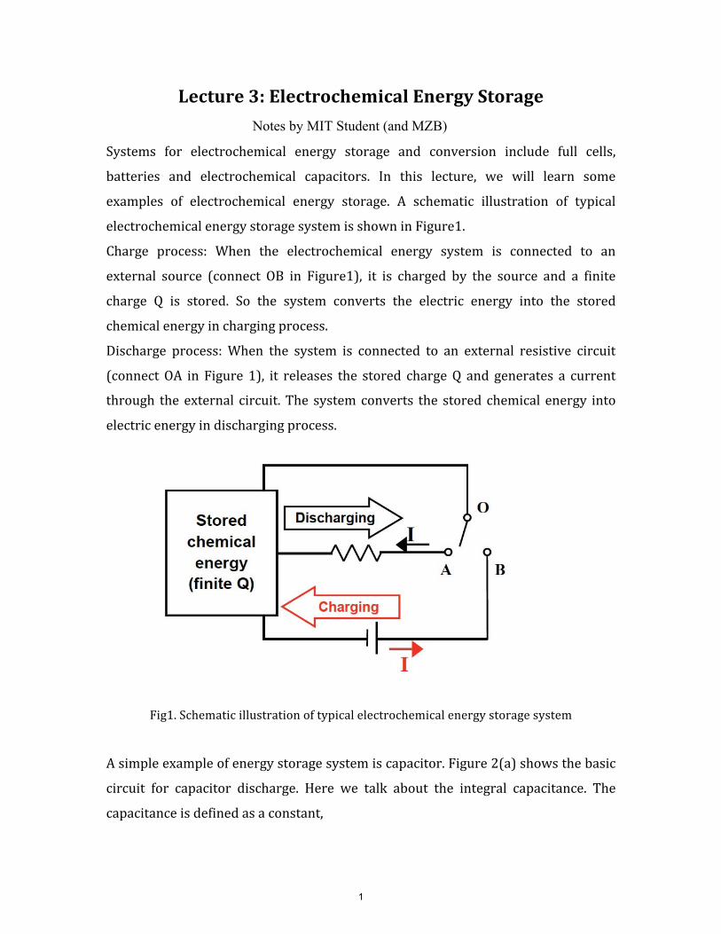
Charge process: When the electrochemical energy system is connected to an
external source (connect OB in Figure1), it is charged by the source and a finite
charge Q is stored. So the system converts the electric energy into the stored
chemical energy in charging process.
Discharge process: When the system is connected to an external resistive circuit
(connect OA in Figure 1), it releases the stored charge Q and generates a current
through the external circuit. The system converts the stored chemical energy into
electric energy in discharging process.
Fig1. Schematic illustration of typical electrochemical energy storage system
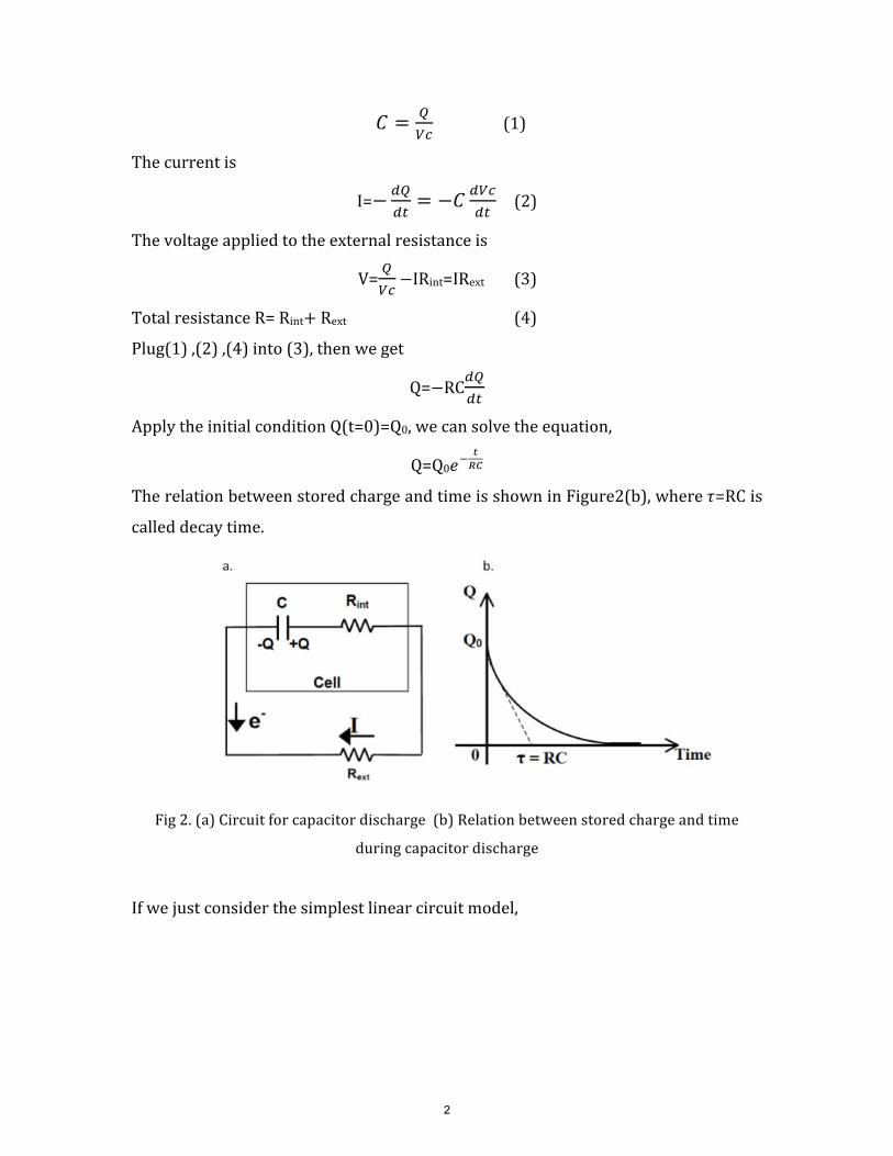
A simple example of energy storage system is capacitor. Figure 2(a) shows the basic
circuit for capacitor discharge. Here we talk about the integral capacitance. The
capacitance is defined as a constant,
Notes by MIT Student (and MZB)
1
Qc = (1)
Vc
The current is
dQ dVcI=- = -c (2)
dt dt
The voltage applied to the external resistance is
V= Q
Vc -IRint=IRext (3)
Total resistance R= Rint+ Rext (4)
Plug(1) ,(2) ,(4) into (3), then we get
dQQ=-RC
dt
Apply the initial condition Q(t=0)=Q0, we can solve the equation,
t -
Q=Q0e RC
The relation between stored charge and time is shown in Figure2(b), where r=RC is
called decay time.
Fig 2. (a) Circuit for capacitor discharge (b) Relation between stored charge and time
during capacitor discharge
If we just consider the simplest linear circuit model,
2
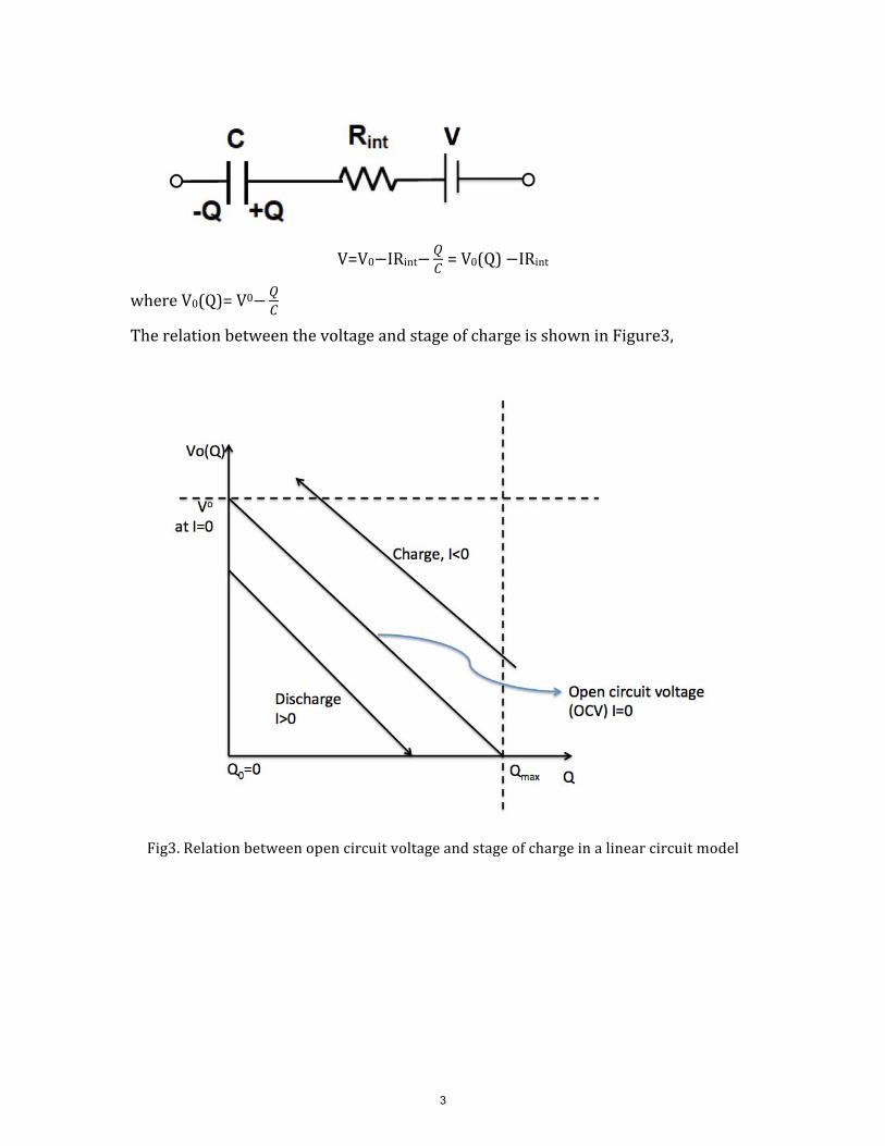
Q V=V0-IRint- = V0(Q)�-IRint
c
Qwhere V0(Q)= V0-
c
The relation between the voltage and stage of charge is shown in Figure3,
Fig3. Relation between open circuit voltage and stage of charge in a linear circuit model
3
In the following sections, we will introduce some practical examples of
electrochemical energy storage.
1. Supercapacitor A supercapacitor is an electrochemical capacitor that has an unusually high energy
density compared to common capacitors, typically on the order of thousands of
times greater than a high capacity electrolytic capacitor. In general, supercapacitors
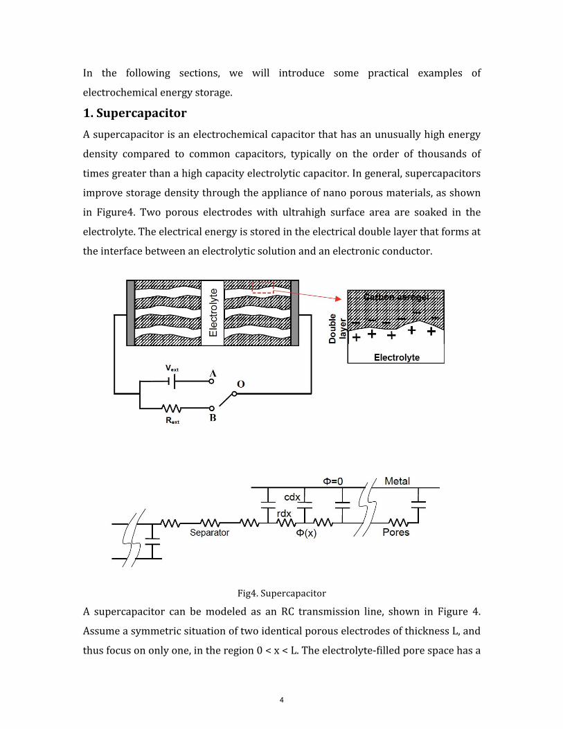
improve storage density through the appliance of nano porous materials, as shown
in Figure4. Two porous electrodes with ultrahigh surface area are soaked in the
electrolyte. The electrical energy is stored in the electrical double layer that forms at
the interface between an electrolytic solution and an electronic conductor.
Fig4. Supercapacitor
A supercapacitor can be modeled as an RC transmission line, shown in Figure 4.
Assume a symmetric situation of two identical porous electrodes of thickness L, and
thus focus on only one, in the region 0 < x < L. The electrolyte-filled pore space has a
4
�
�
constant volume-averaged resistance per length r and constant capacitance per unit
length c. Neglect any resistance in the porous electrode or the thin gap between the
electrodes. The mean potential in the pores satisfies a linear diffusion equation
a< a2<
rc = at ax2
If we apply a sudden change of voltage V for t>0 at x=0, the current response can be
estimated as
2. Primary Battery A primary cell is any kind of battery in which the electrochemical reaction is not
reversible. Primary batteries can produce current immediately on assembly. A
primary cell is not rechargeable because the chemical reactions are not reversible
and active materials may not return to their original forms. Primary batteries are
assembled in the charged state; discharge is the primary process during operation.
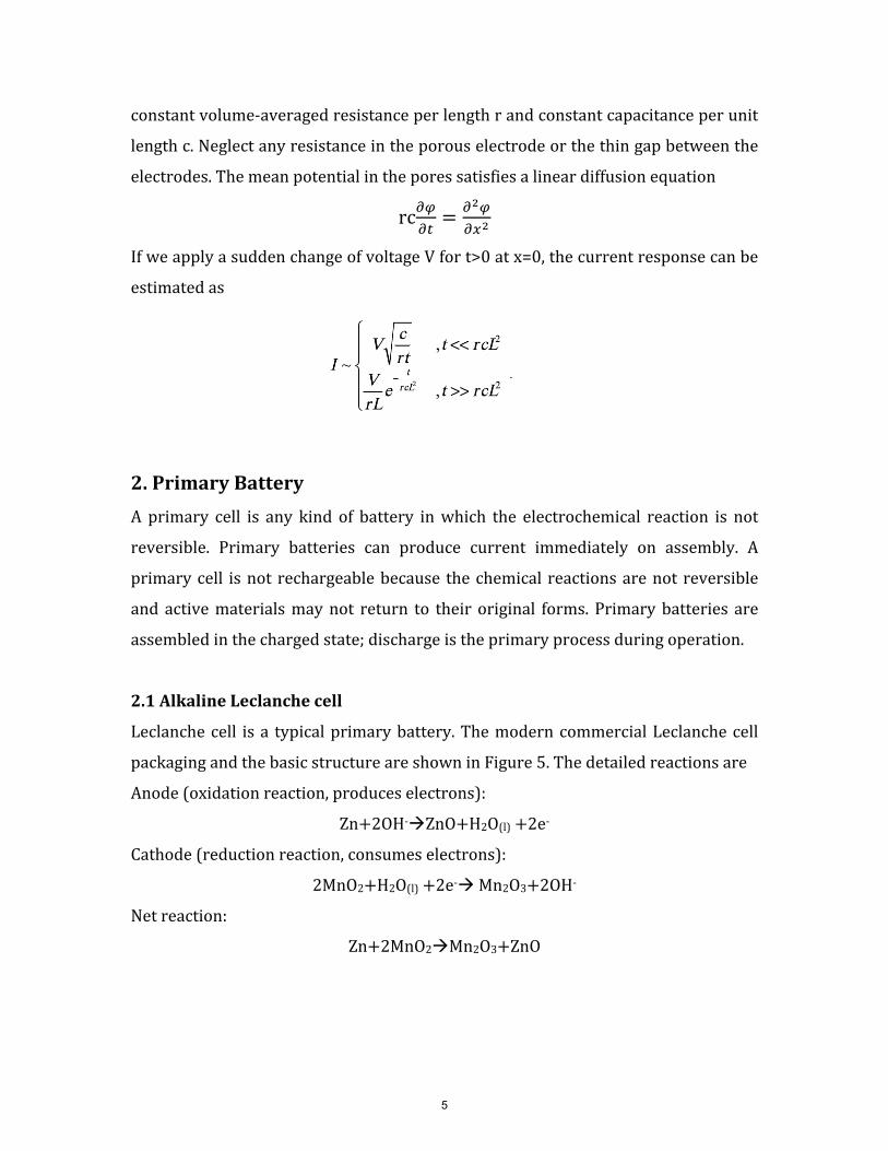
2.1 Alkaline Leclanche cell
Leclanche cell is a typical primary battery. The modern commercial Leclanche cell
packaging and the basic structure are shown in Figure 5. The detailed reactions are
Anode (oxidation reaction, produces electrons):
Zn+2OH-�ZnO+H2O(l) +2e-
Cathode (reduction reaction, consumes electrons):
2MnO2+H2O(l) +2e-� Mn2O3+2OH-
Net reaction:
Zn+2MnO2�Mn2O3+ZnO
5
Fig5. Schematic illustration of Leclanche Zn-MnO2 cell
2.2 Primary Lithium battery Li-MnO2
Primary Li- MnO2 batteries use metallic lithium as anode and manganese dioxide as
cathode, with a salt of lithium dissolved in an organic solvent. Due to the strong
negative potential of metallic lithium, it's possible to obtain high cell voltage (3.7V).
Anode reaction:
Li�Li�+e-
Cathode reaction:
Li�+e-+MnO2�LiMnO2
3. Secondary Battery Secondary batteries are also known as rechargeable batteries because their
electrochemical reactions are electrically reversible. Li-ion battery is a typical
example of secondary battery. Li-ion batteries use intercalated lithium compounds
as electrode materials. Cathode materials, such as LiCoO2, LiMn2O4 and LiFePO4 ,
have been used in commercially available batteries. And the dominant anode
material used in Li-ion batteries is graphite.
6
�
� �
As shown in Figure 6, during discharge, Li ions move from the negative electrode
and intercalate into the positive electrode. And the reverse reaction occurs when the
cell is charging. The process that involves the transfer of Li ions back and forth
between the two electrodes is sometimes called "rocking chair" effect.
Fig6. Schematic illustration of a "rocking-chair" Li-ion battery
Cathode half-reaction is:
LiCoO2� Li1-xCoO2+x Li +x e-
Anode half-reaction is:
x Li +x e-+x C6 � x LiC6
References
1. J.B. Goodenough and K.Park, The Li-Ion Rechargeable Battery: A Perspective. ]. Am. �hem.
Soc. 2013, 135, 1167-1176 7
Schematic illustration of Li-ion battery removed due to copyright restrictions. See:
Goodenough, J. B., and K. Park. "The Li-‐Ion Rechargeable Battery: A Perspective."
Journal of the American Chemical Society 135, no. 4 (2013):1167−76.

2. D. Winter and R.Brodd,What Are Batteries, Fuel Cells, and Supercapacitors? �hem. Rev.
2004, 104, 4245-4269
8

MIT OpenCourseWarehttp://ocw.mit.edu
10.626 Electrochemical Energy SystemsSpring 2014
For information about citing these materials or our Terms of Use, visit: http://ocw.mit.edu/terms.