Embed Size (px)
Citation preview
Lecture – 4
http://home.iitk.ac.in/~mukesh/

Above
Front
Front
Above
1 stQuad
3rd Quad
2nd
4th
•Quadrant 1 and Quadrant 3 are Used for Orthographic Projections•In whatever Quadrant the object is in, viewing directions are same•In what quadrant, so far, we have been keeping the object in?

Object - Plane - Observer
Revisit 3rd Angle Projection SchemeThis is Profile Plane
Here too Observer – Plane - Object
RECAP of Concept

See the positions of Front, top, RS, LS Views
3rd Angle Projection Scheme contd..

1st Angle Projection Scheme
Recap the Concept
•See the positions of Front, top, RS, LS Views•Examine how different these are from 3rd angleprojection•And why?
Plane - Object - Observer
RS Front
Top
LS
Hinge

Concept
In 3rd angle ProjectionObserver – Plane - ObjectPosition wrt Front view;top view is above, R-S View on right and L-S view on left
In 1st angle projectionObserver – Object - Plane
Position wrt Front view;top view is below, R-S View on left and L-S view on right
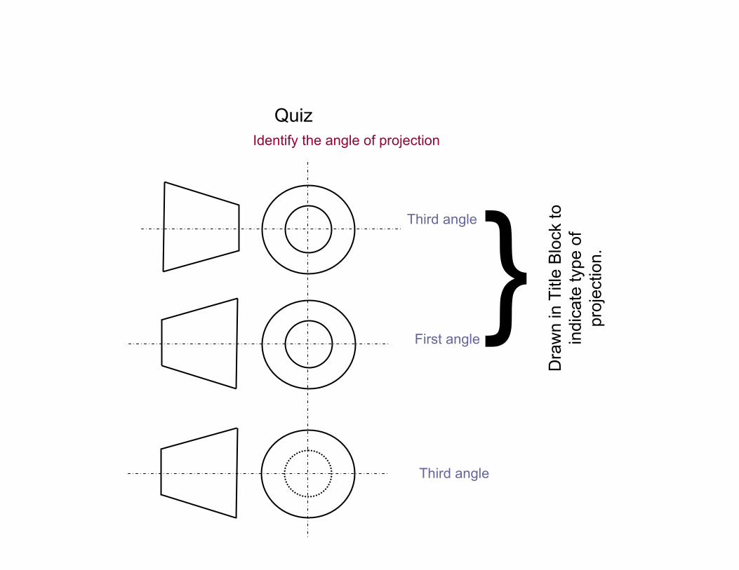
Third angle
Identify the angle of projection
Third angle
First angle
Quiz
Dra
wn
in T
itle
Blo
ck to
in
dica
te ty
pe o
f pr
ojec
tion.

Theory of Dimensioning -Techniques and Conventions
Object is made of several parts – Need
•Position (P)•Size (S)•Each feature is dimensioned once •For each feature, dimension positioned where its shape shows•No Redundancy

S Drill, 2 holes
S(RAD.)
3mm≥8mm
PS
SS
P
P P
S
S
S
S
Extension Lines Dimension Lines Arc and Circular Features
S: SizeP: Position
x=1mm usually
Arrow DimensionsALL DIMENSIONS IN MM
(Near Title Block)x
3x •Avoid giving any dimensions inside the drawing.•No two dimension lines cross each other.•Center line can be used as extension line.
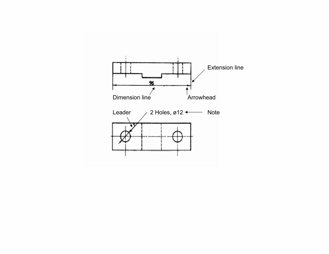
Extension line
ArrowheadDimension line
Leader 2 Holes, ø12 Note

45
60
45
ø40
4520 60
6020
40
ø20
ø60
40
A B
C D
Ø20 Drill

Aligned System Unidirectional Systemvalues read from bottom only(Preferred when?)
values read from bottom and Right side

16
60
16 1030
50
50
Continuous or Chain Dimensioning
20
Progressive or Parallel Dimensioning- From Common Base (Preferred)

Avoid
Avoid
80100
126
450
Areas to avoid – Place them so to read conveniently
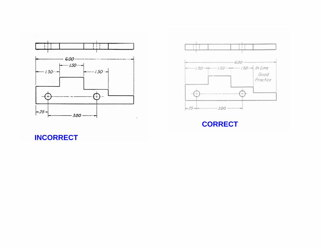
INCORRECT
CORRECT
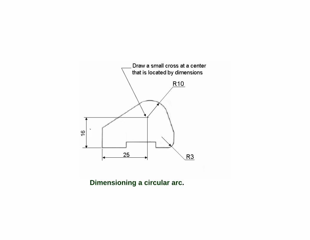
Dimensioning a circular arc.
16

Omit unnecessary dimensions.
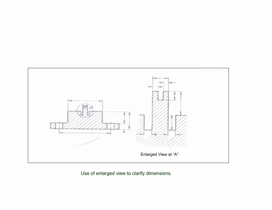
Enlarged View at “A”
Use of enlarged view to clarify dimensions.

Dimensioning of arcs
Single arrow, inclined, show where true shape

Equally spaced holes.
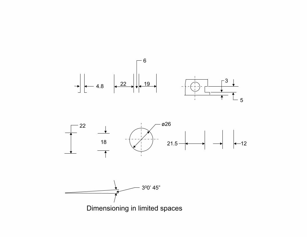
4.8 22 19
18
22 ø26
21.5 12
3
5
300’ 45”
6
Dimensioning in limited spaces