Embed Size (px)
Citation preview
Lecture 4
Unified Process Disciplines Phases
Requirements Use case models
UML Use Case Diagrams Class Diagrams Sequence Diagrams Statechart Diagrams
Hat Problem Three persons each one wearing a hat that is
either red or blue with 50% probability. A person can see the colours of the other two
hats but not its own colour. Each player can either make no prediction or
give a guess on the colour of its own hat. The team wins if at least one player guessed
correctly and no player guessed a wrong answer.
There is no form of communication between the players, in particular they do not know which decision any of the other players made.
The players can agree beforehand on a common fixed strategy.
Unified Process
The UP describes work activities, such as writing a use-cas model, within disciplines.
In the UP an artefact, is the general term for any work product, code, diagrams, models, database schema etc. .
There are several disciplines in the UP, business modeling, requirements, design, implementation, test, deployment, configuration and change management.
The course focuses on requirement analysis, design and implementation.
Unified Process
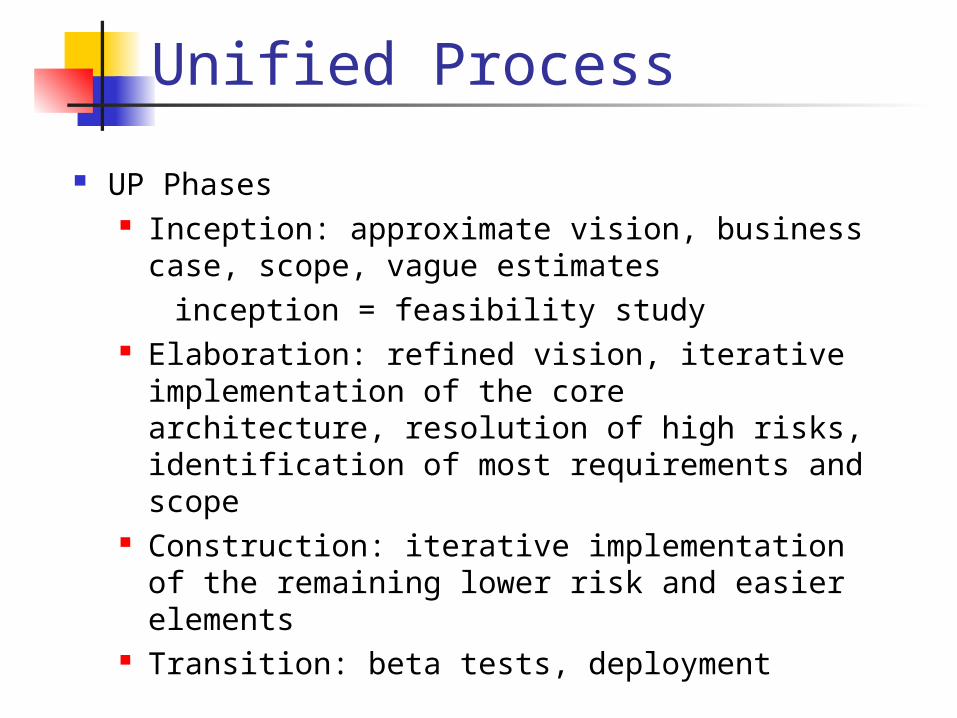
UP Phases Inception: approximate vision, business
case, scope, vague estimates inception = feasibility study Elaboration: refined vision, iterative
implementation of the core architecture, resolution of high risks, identification of most requirements and scope
Construction: iterative implementation of the remaining lower risk and easier elements
Transition: beta tests, deployment
Unified Process
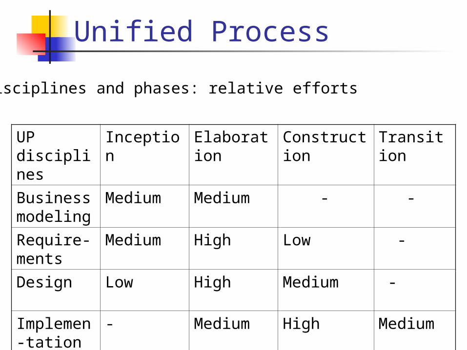
UP disciplines
Inception Elaboration
Construction
Transition
Business modeling
Medium Medium - -
Require-ments
Medium High Low -
Design Low High Medium -
Implemen-tation
- Medium High Medium
Disciplines and phases: relative efforts
Unified Modeling Language
UML a complete language for capturing knowledge (semantics) about a subject and expressing knowledge (syntax) regarding the subject.
Modeling involves a focus on understanding (knowing) a subject (system) and capturing and being able to communicate this knowledge.
UML is the result of unifying the information systems and technology industry´s best engineering practices (principles, techniques, methods and tools)
UML is a notation not a method !!!
Unified Modeling Language
UML is used for specification, visualization and documentation of systems
UML is based on the object oriented paradigm UML applies to a multitude of different types of
systems, domains and methods or processes. UML unifies the syntax and semantics of methods
and tools previously used for object oriented design UML was originally conceived by Rational Software
Corporation and the ”Three Amigos” in 1995 Grady Booch James Rumbaugh Ivar Jacobson
DIA DIA is a diagram creation program from Linkoeping
University http://www.lysator.liu.se/~alla/dia/dia.html
It can be used to draw many different kinds of diagrams Entity relationship diagrams UML diagrams Flowcharts Network diagrams
It is available by adding the module dia module add dia
dia
Use Case Model
Writing use cases is an excellent technique to understand and describe requirements.
A use case is a story of using the system. The Unified Process defines the Use-Case
Model within the requirements discipline. The set of all Use-Cases provides a model of
the system’s functionality and environment.
Use Cases
An actor is something with behavior, such as a person (identified by a role), computer system or organization, for example a cashier.
A scenario is a specific sequence of actions and interactions between actors and the system under investigation, it is also called a use case instance, for example purchasing an item with cash.
A use case is a collection or related scenarios that describe actors using the system to support a goal.
Actors
Actors are classes that define roles that objects external to a system may play. They are used to model users outside of a system that interact directly with the system as part of coherent work units. This includes human users and other systems
Actors are characterized by their external view rather than their internal structure.
Actors participate in interactions involving message exchanges and actions with systems.
Actors have goals to be achieved by interacting with the system.
Use Cases
Uses cases are entities that define units of functionality or behavior provided by the system.
Use cases specify the external requirements of the system and the functionality offered by the system.
Use cases are specified by sequence diagrams representing the external interaction sequences among the systems and its actors.
Use cases are realized, or implemented, by collaboration diagrams representing the internal refinement of the services provided by the system.
Use Cases
When writing use cases you should ask the question: “How can using the system provide observable value to the user or fulfill their goals.”
Use cases describe the functional requirements of a system, that indicate what the system is supposed to do.
Use cases are primarily text documents (written stories) although the may contain UML use case diagrams, to illustrate the names of use cases and actors and their relationship.
Use Cases
Use cases describe the system as having responsibilities, they do not describe the internal workings of the system. They specify what the system must do (functional requirements) not how (design) it will do it.
Incorrect: The system writes the sale to a database.
Instead: The system records the sale.
Use Cases
Formats for use cases Brief : one-paragraph summary,
usually of the main success scenario Casual : multiple paragraphs that
cover various scenarios Fully dressed : elaborate description,
all steps and variations are written in detail, there are supporting sections, such as pre-conditions and success guarantees.
Use Cases
Example (brief format):Borrow book : A library user arrives at the
check-out with books to borrow. The patron identifies herself to the check-out system and the system validates that she is a legitimate user. The patron uses the check-out system to record each borrowed book. The system validates, records each book and associates the book with the patron. The system updates the library inventory. The patron receives a receipt from the system that states the books borrowed and the loan period.
Requirement Analysis
Finding primary actors, goals and use cases Choose the system boundary Identify the primary actors Identify the goals of the actors Define uses cases that satisfy user
goals
Use Cases
Borrow book : Primary actor : patronStakeholders and Interests:
-patron : Wants to borrow and return books quickly and with minimal effort. Wants receipt over borrowed and returned books.
-librarian : Wants system to accurately record transactions. Wants fast access to and automatic update of library inventory.
-library : Wants to reduce operation costs. Wants reliable capture of transactions.
Use Case Diagrams
Use case diagrams render the user view of a system.
Use case diagrams describe the functionality provided by the system or class to external actors.
Use case diagrams contain Actors Use cases Their relationships
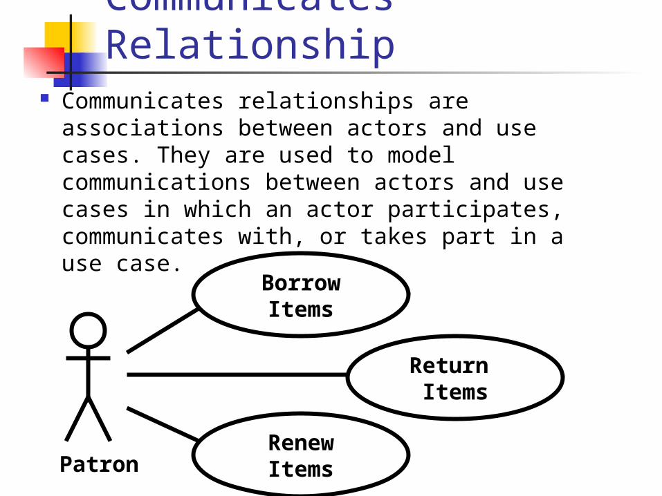
Communicates Relationship
Communicates relationships are associations between actors and use cases. They are used to model communications between actors and use cases in which an actor participates, communicates with, or takes part in a use case.
BorrowItems
Return Items
PatronRenewItems
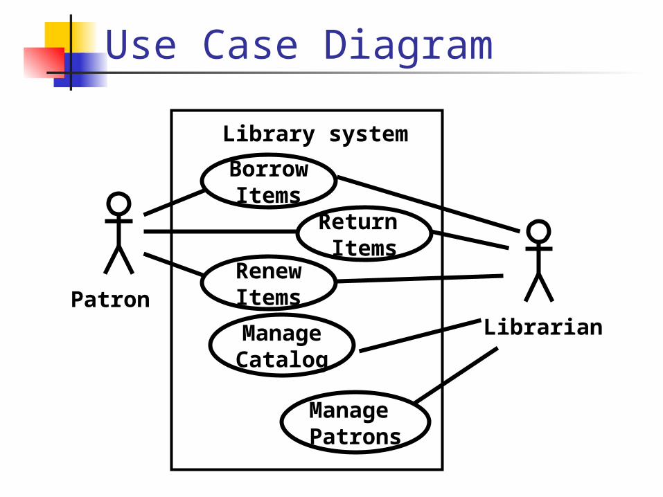
Use Case Diagram
Library system
BorrowItems
Return Items
PatronRenewItems
ManageCatalog
Manage Patrons
Librarian
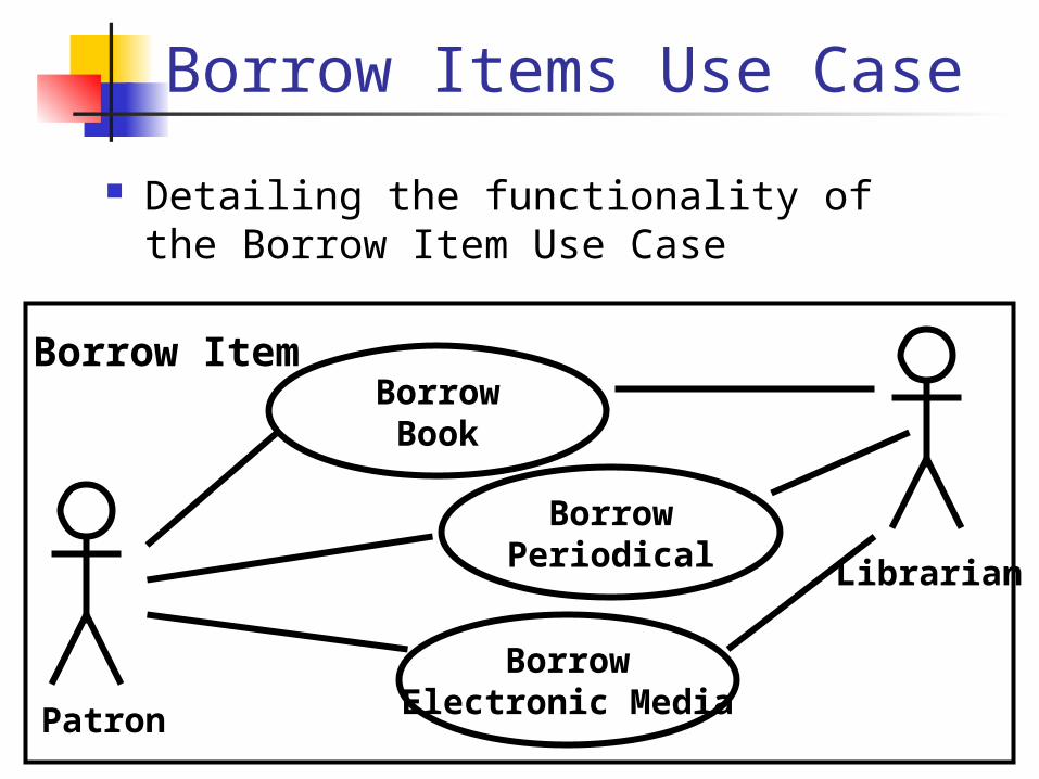
Borrow Items Use Case
Detailing the functionality of the Borrow Item Use Case
BorrowBook
BorrowPeriodical
Patron
BorrowElectronic Media
Borrow Item
Librarian
Extends Relationships
Extends relationships are generalizations between use cases. They are used to model relationships between use cases in which a base use case instance may include the behavior specified by an extending use case, subject to conditions specified in the extension.
Extends relationships are used to capture exceptional behavior or variations of normal behavior.
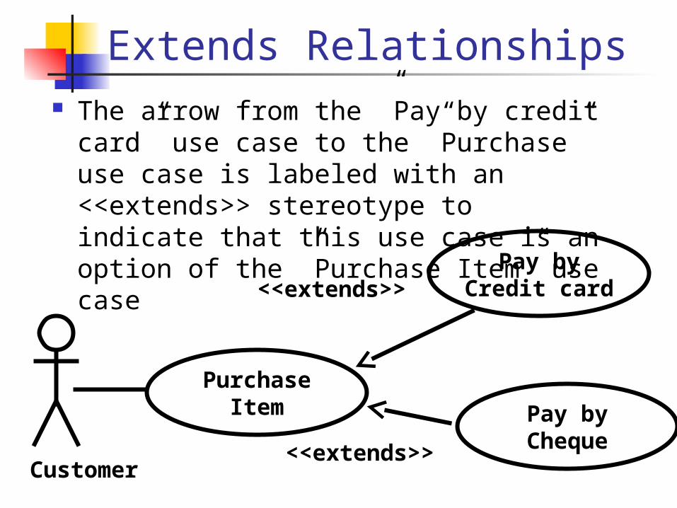
Extends Relationships The arrow from the ”Pay by credit card”
use case to the ”Purchase” use case is labeled with an <<extends>> stereotype to indicate that this use case is an option of the ”Purchase Item” use case
PurchaseItem
Pay byCredit card
Customer
<<extends>>
Pay byCheque<<extends>>
Uses Relationships
Uses relationships are generalizations between use cases. They are used to model relationships between use cases in which a base use case instance will also include the behavior specified by a common use case.
Use relationships are used to share common behavior among use cases.
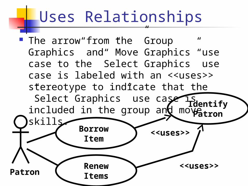
Uses Relationships The arrow from the ”Group Graphics”
and ”Move Graphics” use case to the ”Select Graphics” use case is labeled with an <<uses>> stereotype to indicate that the ”Select Graphics” use case is included in the group and move skills.
Borrow Item
IdentifyPatron
Patron<<uses>>Renew
Items
<<uses>>
Unified Modeling Language
UML object model describes the static structure of the problem domain, it contains Class diagram
describes the class attributes (name and type), operations and the relationship among classes. A class diagram contains classes and associations
Object diagramA class model describes all possible
situation, whereas an object model describes a particular situation. An object diagram contains objects and links which represent the relationship between objects
Unified Modeling Language
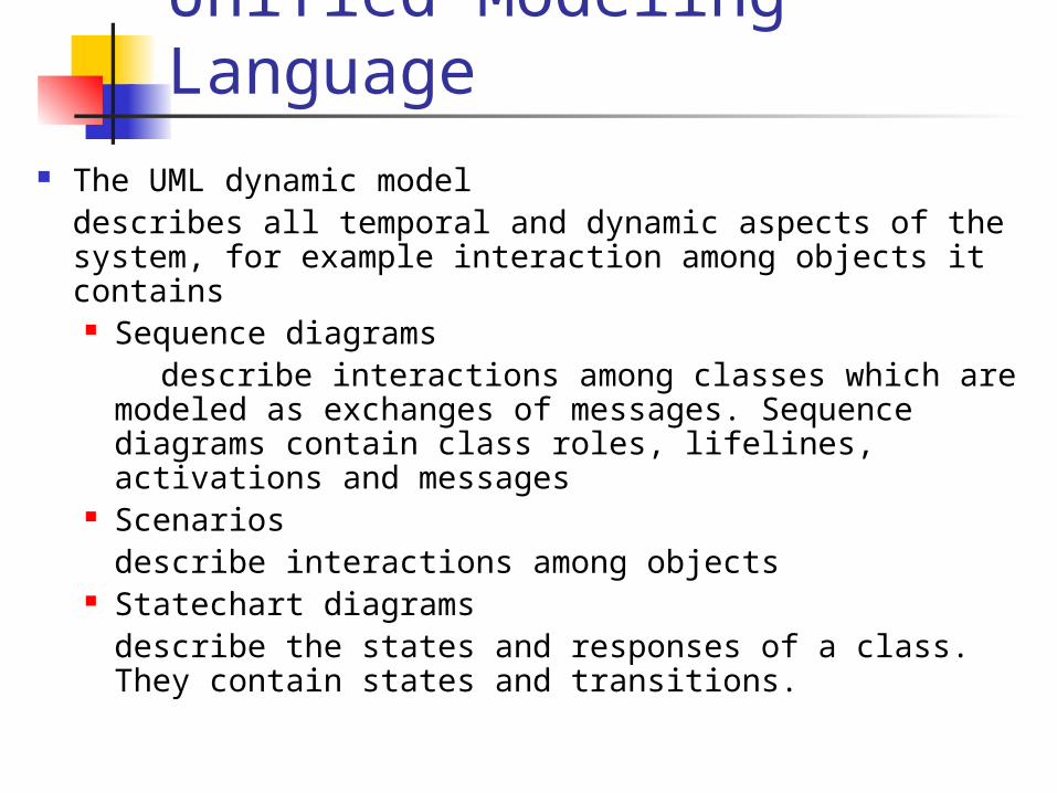
The UML dynamic modeldescribes all temporal and dynamic aspects of the system, for example interaction among objects it contains Sequence diagrams describe interactions among classes which are
modeled as exchanges of messages. Sequence diagrams contain class roles, lifelines, activations and messages
Scenariosdescribe interactions among objects
Statechart diagramsdescribe the states and responses of a class. They contain states and transitions.
Domain Model & Design Model
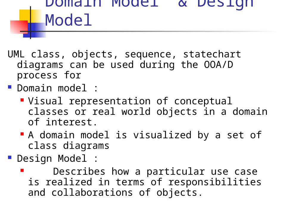
UML class, objects, sequence, statechart diagrams can be used during the OOA/D process for
Domain model : Visual representation of conceptual classes
or real world objects in a domain of interest. A domain model is visualized by a set of
class diagrams Design Model :
Describes how a particular use case is realized in terms of responsibilities and collaborations of objects.
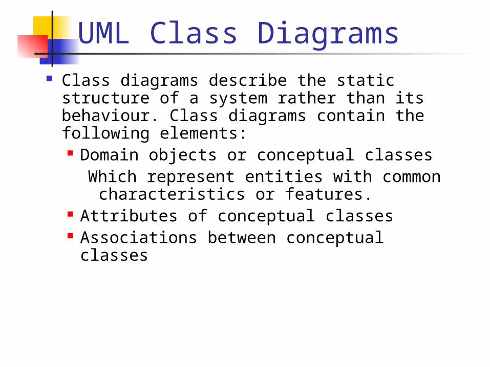
UML Class Diagrams Class diagrams describe the static
structure of a system rather than its behaviour. Class diagrams contain the following elements: Domain objects or conceptual classes
Which represent entities with common characteristics or features.
Attributes of conceptual classes Associations between conceptual classes
Class Diagram
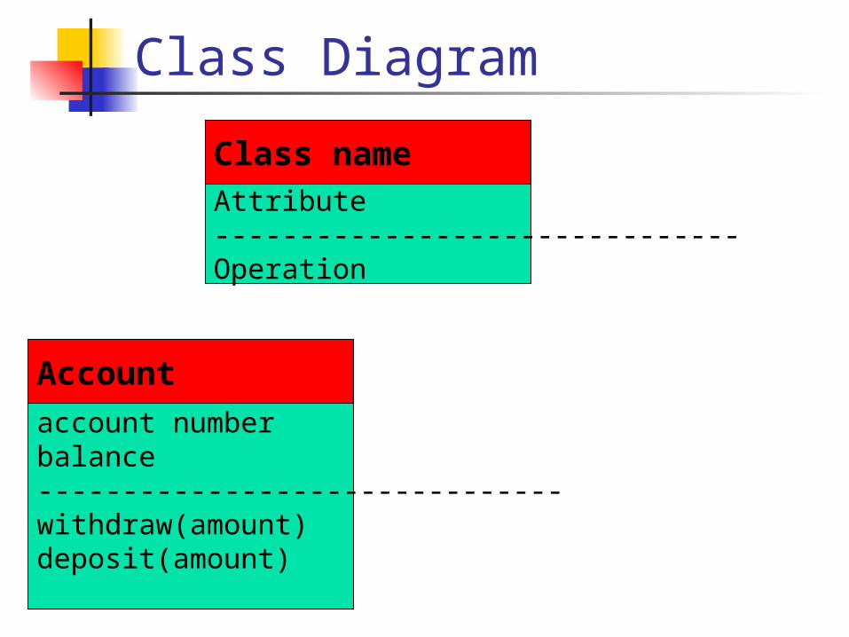
account number balance-------------------------------withdraw(amount) deposit(amount)
Account
Attribute-------------------------------Operation
Class name
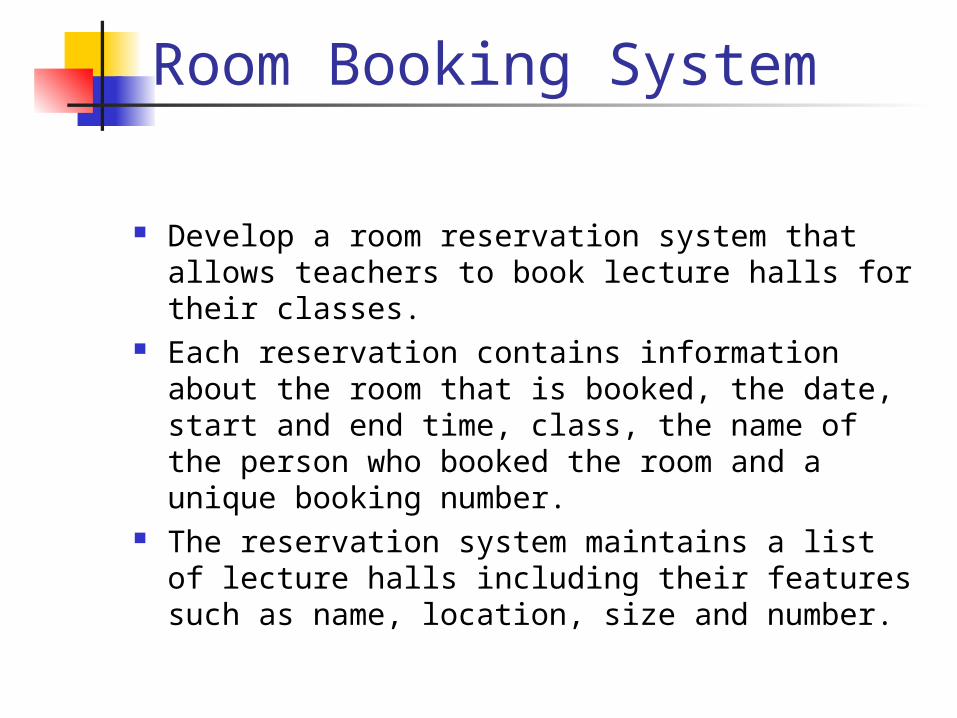
Room Booking System
Develop a room reservation system that allows teachers to book lecture halls for their classes.
Each reservation contains information about the room that is booked, the date, start and end time, class, the name of the person who booked the room and a unique booking number.
The reservation system maintains a list of lecture halls including their features such as name, location, size and number.
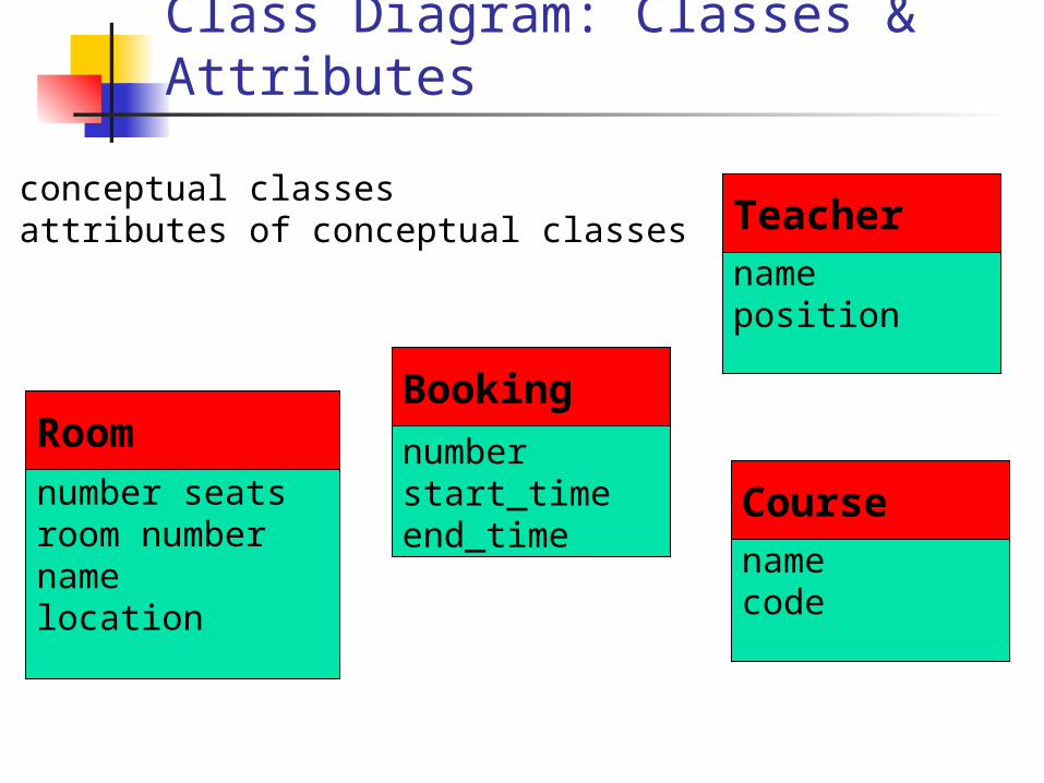
Class Diagram: Classes & Attributes
number seatsroom numbernamelocation
Room numberstart_timeend_time
Booking
nameposition
Teacher
namecode
Course
• conceptual classes• attributes of conceptual classes
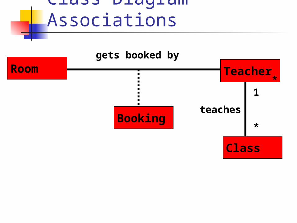
Class Diagram Associations
Room
Booking
Teacher
Class
* *
gets booked by
1
*
teaches
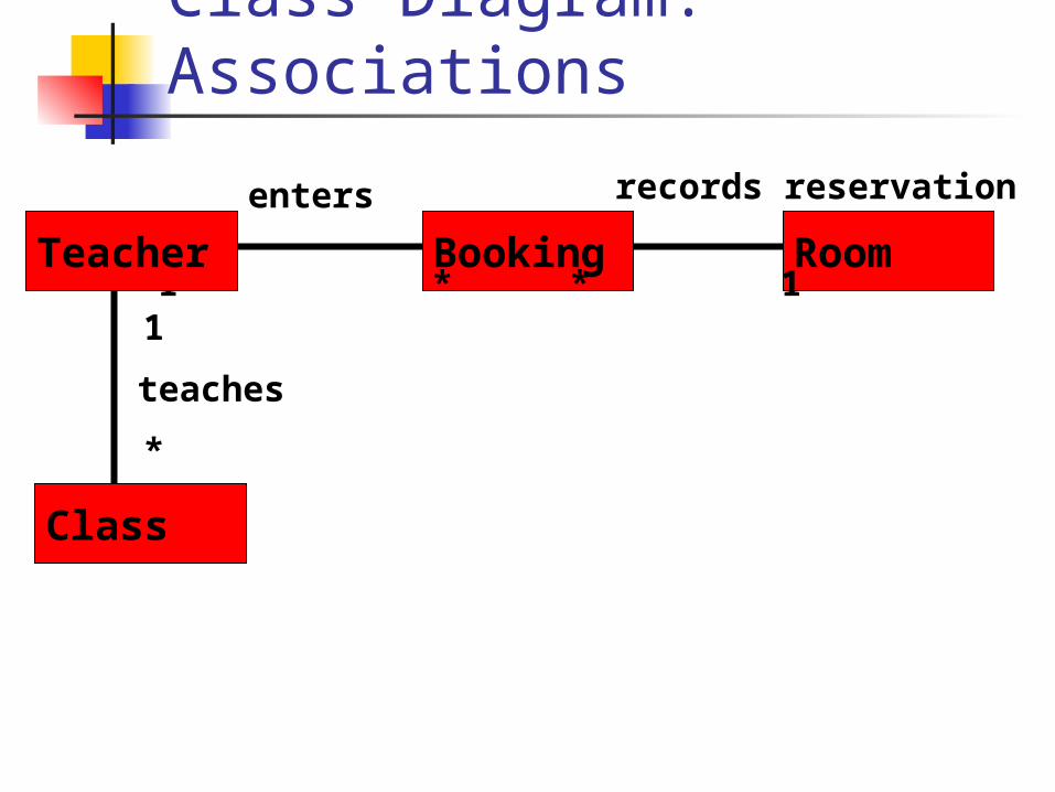
Class Diagram: Associations
RoomBooking1 *
records reservation
teaches
enters
* 1 Teacher
Class
1
*
Multiplicity of Associations
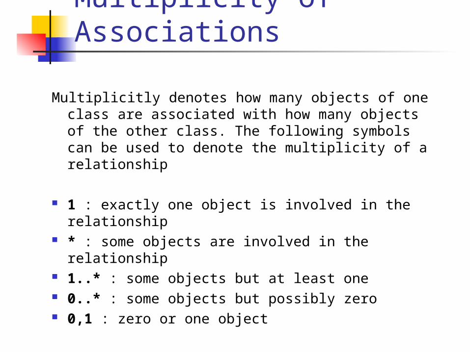
Multiplicitly denotes how many objects of one class are associated with how many objects of the other class. The following symbols can be used to denote the multiplicity of a relationship
1 : exactly one object is involved in the relationship
* : some objects are involved in the relationship
1..* : some objects but at least one 0..* : some objects but possibly zero 0,1 : zero or one object
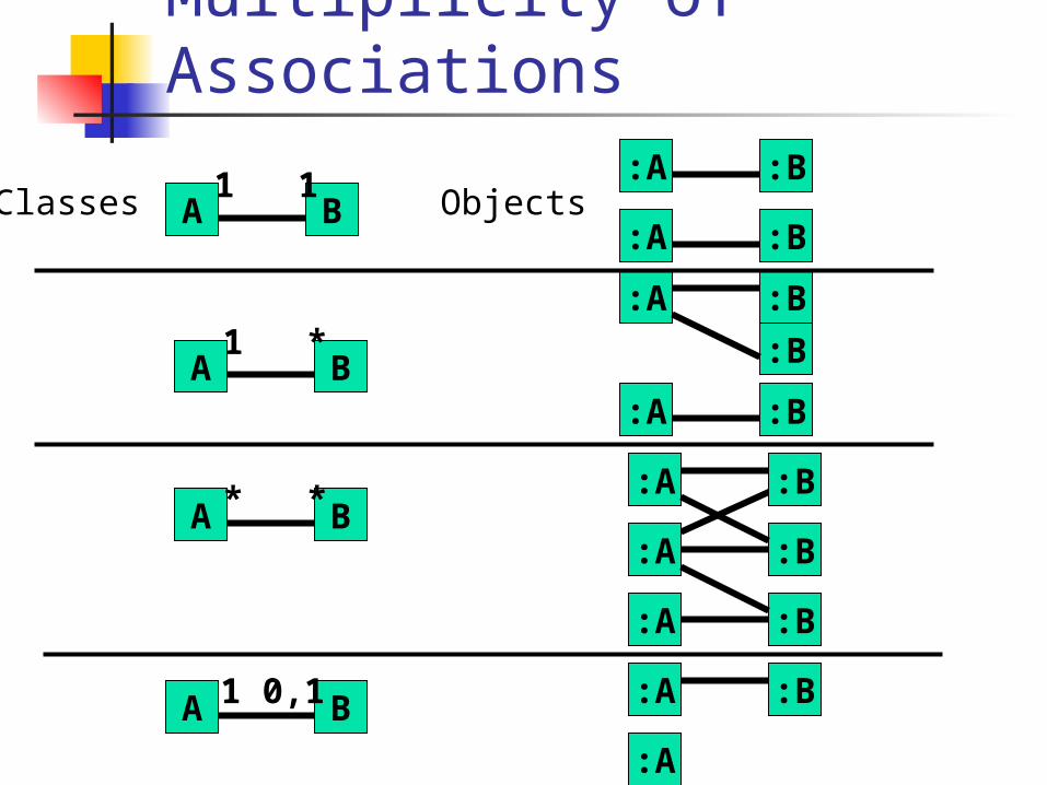
Multiplicity of Associations
A B1 1 :A :B
Classes Objects:A :B
A B1 *
:A :B
:B
A B* * :A :B
:A :B
:A :B
A B1 0,1 :A :B
:A
:A :B
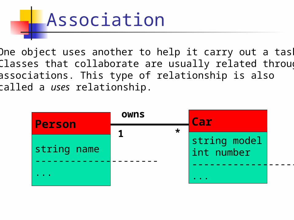
Association
One object uses another to help it carry out a task.Classes that collaborate are usually related throughassociations. This type of relationship is alsocalled a uses relationship.
string name---------------------...
Personstring modelint number---------------------...
Carowns
1 *
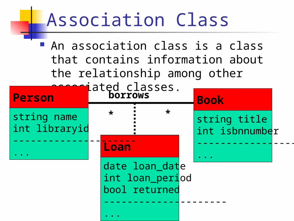
Association Class An association class is a class that
contains information about the relationship among other associated classes.
date loan_dateint loan_periodbool returned---------------------...
Loan
string titleint isbnnumber---------------------...
Bookborrows
* *string nameint libraryid---------------------...
Person
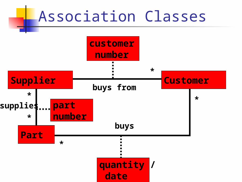
Association Classes
Part
Customerbuys from
*
*Supplier
customer number
partnumber
supplies
*buys
quantity / date
*
*
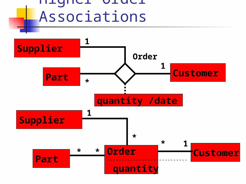
Higher Order Associations
PartCustomer
1Supplier
Order----------------------------
quantity
*1
Part Customer
1Supplier
quantity /date
*
Order1
**
*
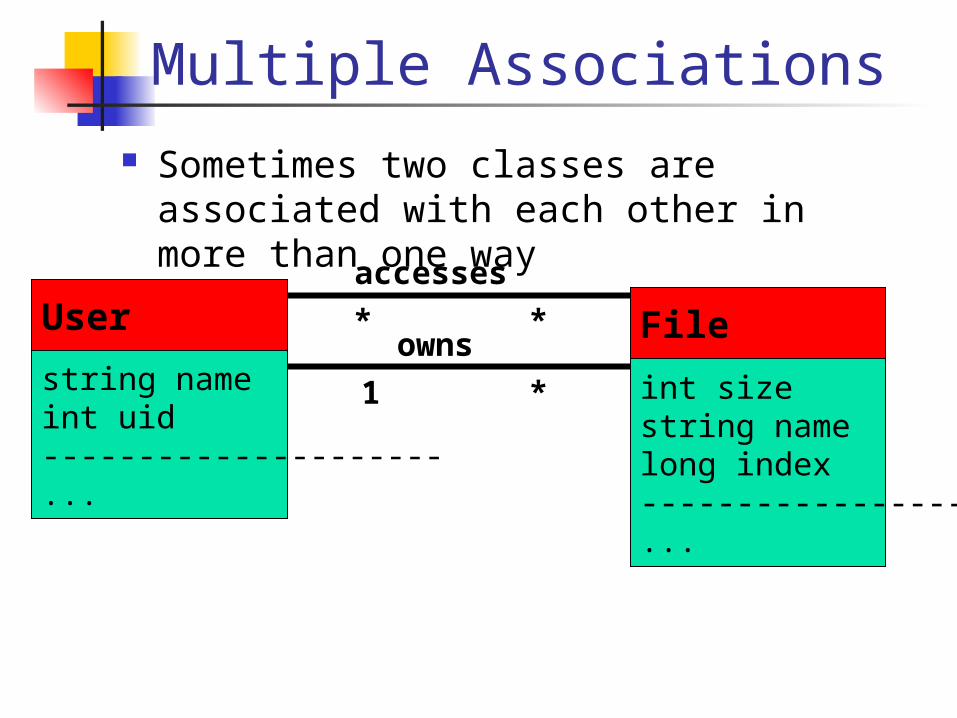
Multiple Associations Sometimes two classes are associated
with each other in more than one way
int sizestring namelong index---------------------...
Fileaccesses
* *
string nameint uid---------------------...
Userowns
1 *
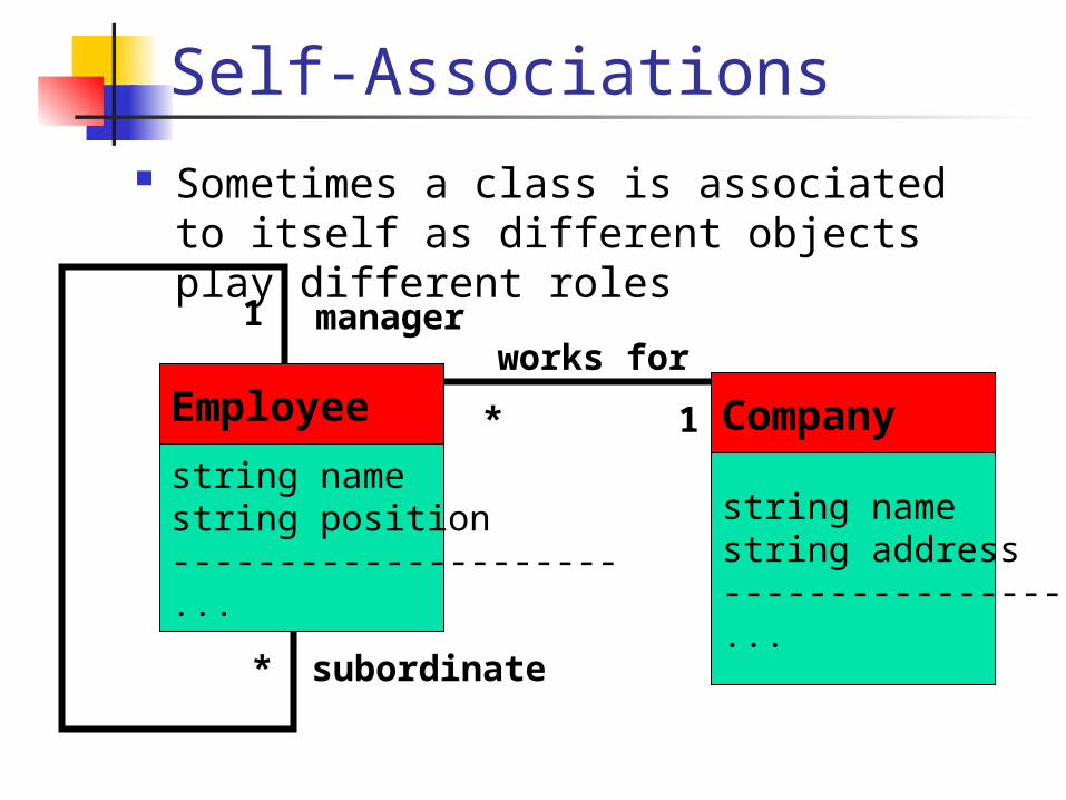
Self-Associations Sometimes a class is associated to itself
as different objects play different roles
string namestring address---------------------...
Companyworks for
*
1
string namestring position---------------------...
Employee
manager
subordinate
*
1
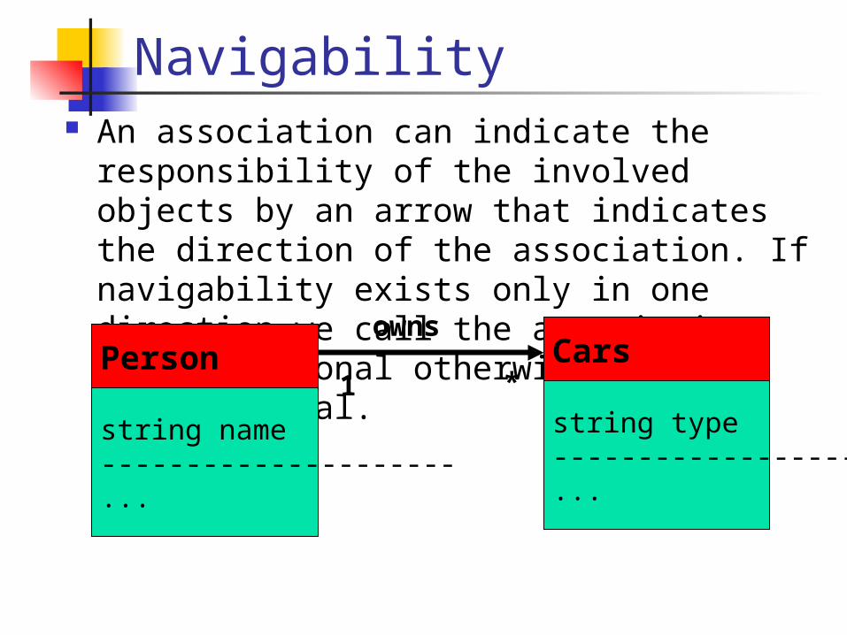
Navigability An association can indicate the
responsibility of the involved objects by an arrow that indicates the direction of the association. If navigability exists only in one direction we call the association uni-directional otherwise bidirectional.
string name---------------------...
Person
string type---------------------...
Carsowns
1 *
Aggregation
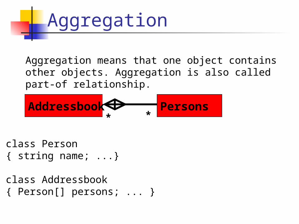
Aggregation means that one object contains other objects. Aggregation is also called part-of relationship.
Addressbook Persons* *
class Person{ string name; ...}
class Addressbook{ Person[] persons; ... }
Aggregation
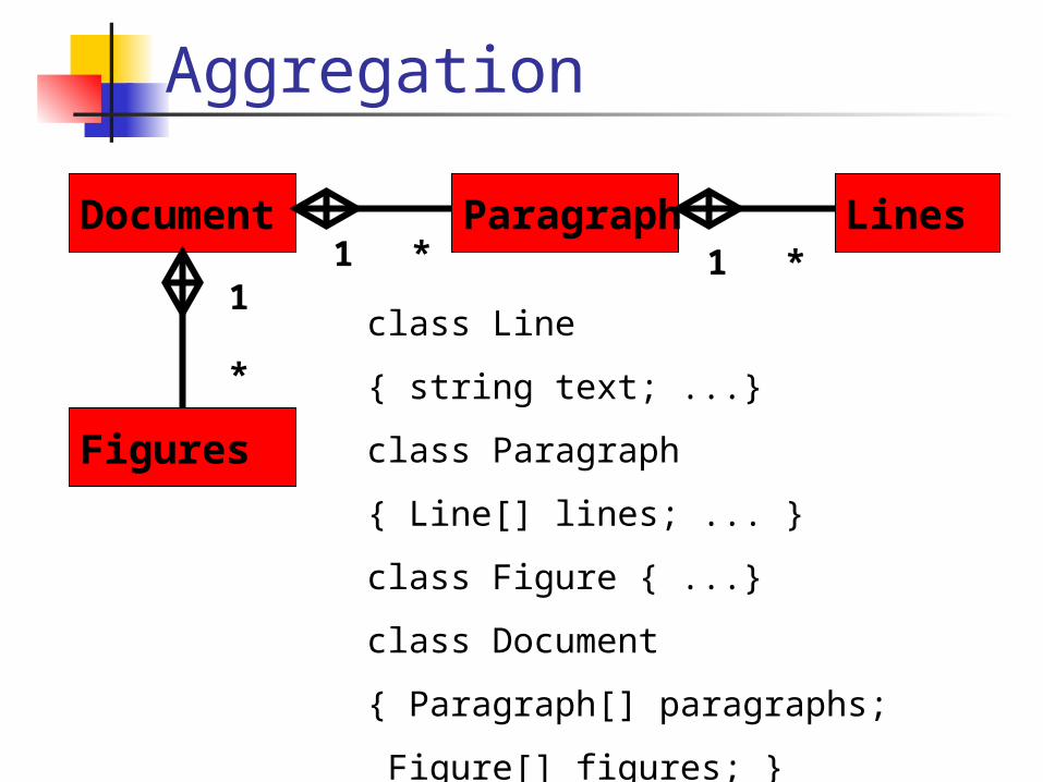
Document Paragraph Lines
Figures
1 * 1 *1
*
class Line
{ string text; ...}
class Paragraph
{ Line[] lines; ... }
class Figure { ...}
class Document
{ Paragraph[] paragraphs;
Figure[] figures; }
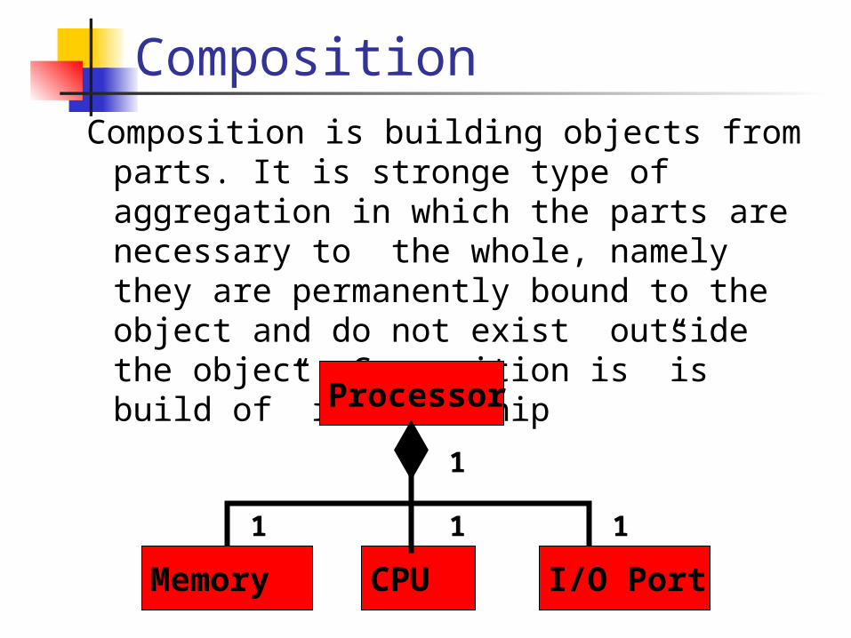
CompositionComposition is building objects from parts.
It is stronge type of aggregation in which the parts are necessary to the whole, namely they are permanently bound to the object and do not exist outside the object. Composition is ”is build of” relationship
Processor
CPU
1
1
Memory I/O Port
1 1
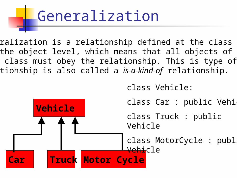
Generalization
Generalization is a relationship defined at the class level not the object level, which means that all objects of this class must obey the relationship. This is type of relationship is also called a is-a-kind-of relationship.
Vehicle
Car Truck Motor Cycle
class Vehicle:
class Car : public Vehicle
class Truck : public Vehicle
class MotorCycle : public Vehicle
Sequence Diagrams
Sequence diagrams describe interactions among classes. These interactions are modeled as exchanges of messages.
Sequence diagrams focus on classes and the messages they exchange to accomplish some desired behavior.
Sequence Diagrams
Sequence diagrams are a type of interaction diagrams that contain Class roles represent roles that
objects may play within the interaction.
Lifelines represent the existence of an object over a period of time.
Activations represent the time during which an object is performing an operation.
Messages represent communications between objects.
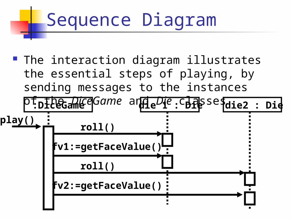
Sequence Diagram
The interaction diagram illustrates the essential steps of playing, by sending messages to the instances of the DiceGame and Die classes.:DiceGame
roll()
die 1 : Die die2 : Die
fv1:=getFaceValue()
play()
roll()
fv2:=getFaceValue()
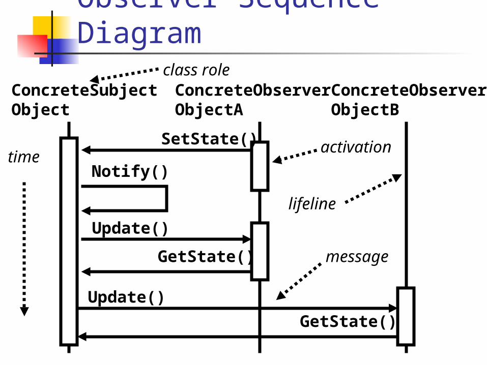
Observer Sequence Diagram
ConcreteSubjectObject
ConcreteObserverObjectA
ConcreteObserverObjectB
Notify()
SetState()
Update()
GetState()
Update()
GetState()
time
class role
message
activation
lifeline
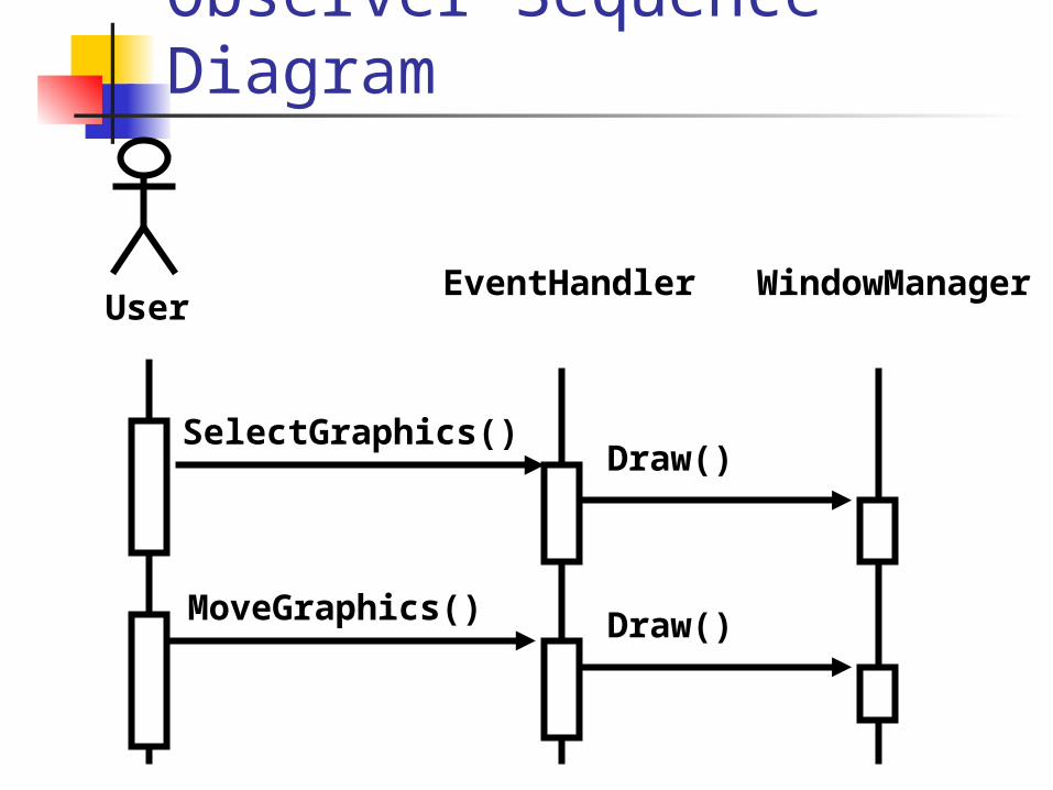
Observer Sequence Diagram
EventHandler
SelectGraphics()
Draw()
UserWindowManager
MoveGraphics()
Draw()
UML Statechart Diagrams
Statechart diagrams lie within the behavioral view of a system and render the states and responses of a class.
Statechart diagrams describe the behaviour of a class in response to external stimuli.
Statechart diagrams describe the life cycle of an object.
Statechart diagrams contain States Transitions
Finite State Machines (FSM)
States An FSM is exactly in one current state. An FSM has an initial state. An FSM may change state due to a
transition. Transitions
Transitions connect states with each other.
Transitions carry a label or a guard condition that triggers the transition.
Transitions can be defined by a transition matrix.
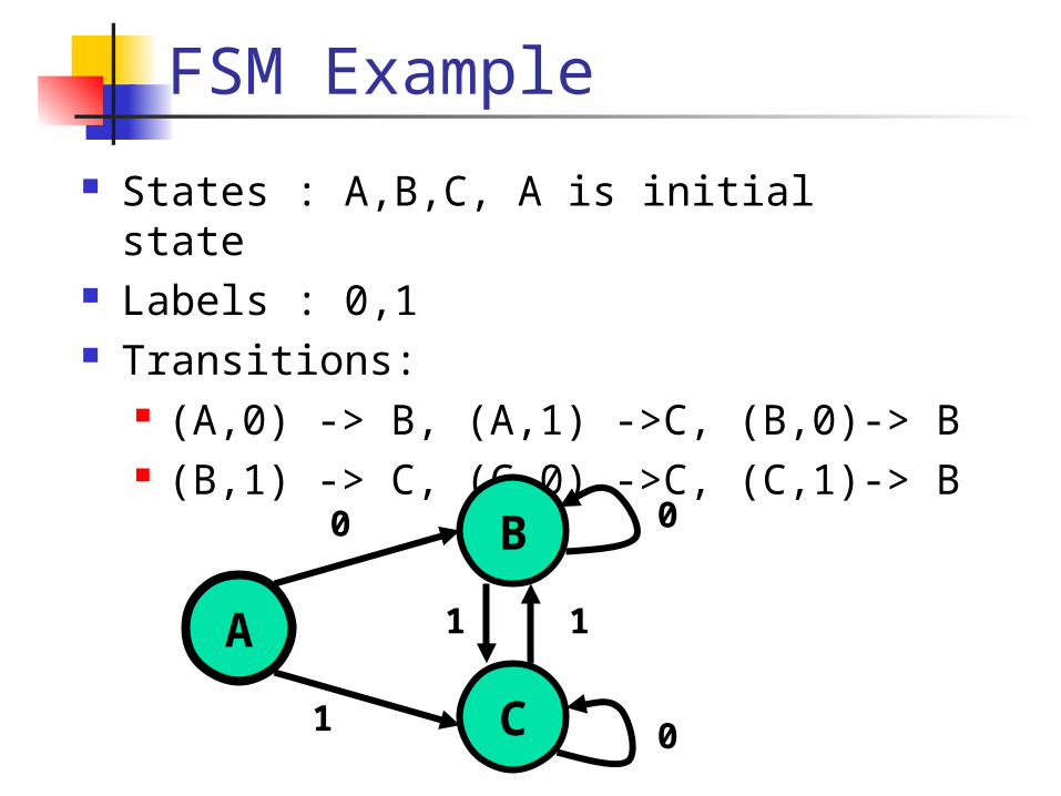
FSM Example
States : A,B,C, A is initial state Labels : 0,1 Transitions:
(A,0) -> B, (A,1) ->C, (B,0)-> B (B,1) -> C, (C,0) ->C, (C,1)-> B
A
B
C
0
1
0
0
11
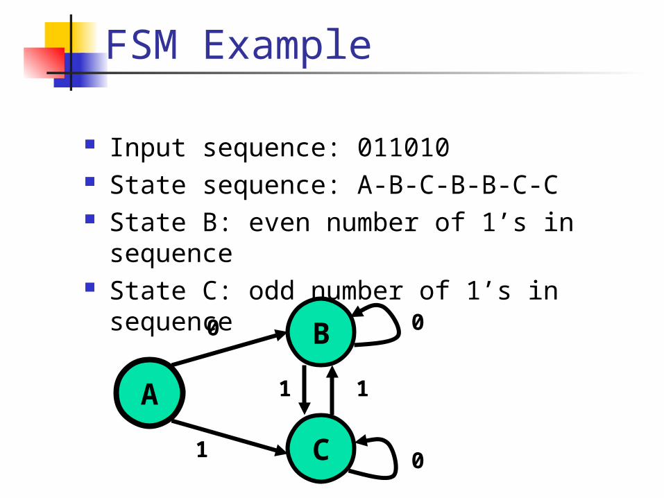
FSM Example
Input sequence: 011010 State sequence: A-B-C-B-B-C-C State B: even number of 1’s in
sequence State C: odd number of 1’s in sequence
A
B
C
0
1
0
0
11
Statechart Diagrams
States are classes that define status conditions that an object may satisfy during its existence.
States are used to model the situations during the life of an entity in which it satisfies some condition, performs some activity, or waits for some occurence.
An entity remains in a state for a finite and non-instantaneous time.
Statechart Diagrams
Transitions are associations between states. They are used to model relationships between the different states of an entity.
An entity in one state will perform actions and possibly enter another state when an event occurs and a condition is satisfied (if specified), this occurence is known as the firing of a transition.
Statechart Diagrams
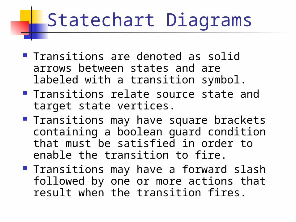
Transitions are denoted as solid arrows between states and are labeled with a transition symbol.
Transitions relate source state and target state vertices.
Transitions may have square brackets containing a boolean guard condition that must be satisfied in order to enable the transition to fire.
Transitions may have a forward slash followed by one or more actions that result when the transition fires.
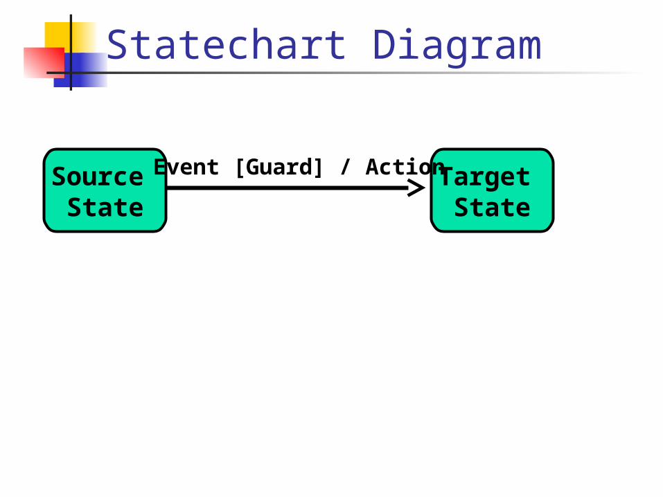
Statechart Diagram
Source State
Target State
Event [Guard] / Action
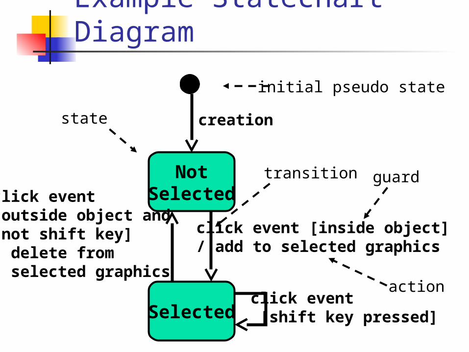
Example Statechart Diagram
NotSelected
Selected
transition
creation
click event [inside object] / add to selected graphics
click event[outside object and not shift key] / delete from selected graphics
click event [shift key pressed]
initial pseudo state
guard
action
state
Hat Problem
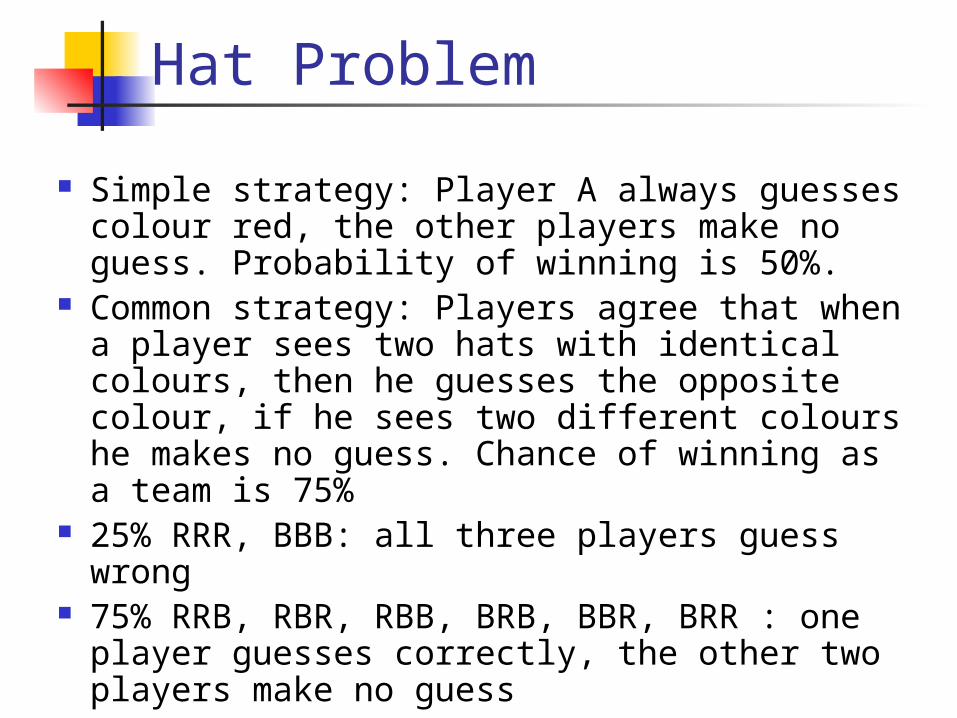
Simple strategy: Player A always guesses colour red, the other players make no guess. Probability of winning is 50%.
Common strategy: Players agree that when a player sees two hats with identical colours, then he guesses the opposite colour, if he sees two different colours he makes no guess. Chance of winning as a team is 75%
25% RRR, BBB: all three players guess wrong 75% RRB, RBR, RBB, BRB, BBR, BRR : one
player guesses correctly, the other two players make no guess