Embed Size (px)
Citation preview
Lecture B
Electrical circuits, power supplies and passive circuit elements
Electrical Circuits• We want to transfer electrical energy to perform a task
• We want to supply energy to some load
• Charged particles want to “move” when an emf applied• Apply emf and constrain the path of the charged particles• Force charged particles to supply energy to the load in order
to do work (no path through load no useful work done!)
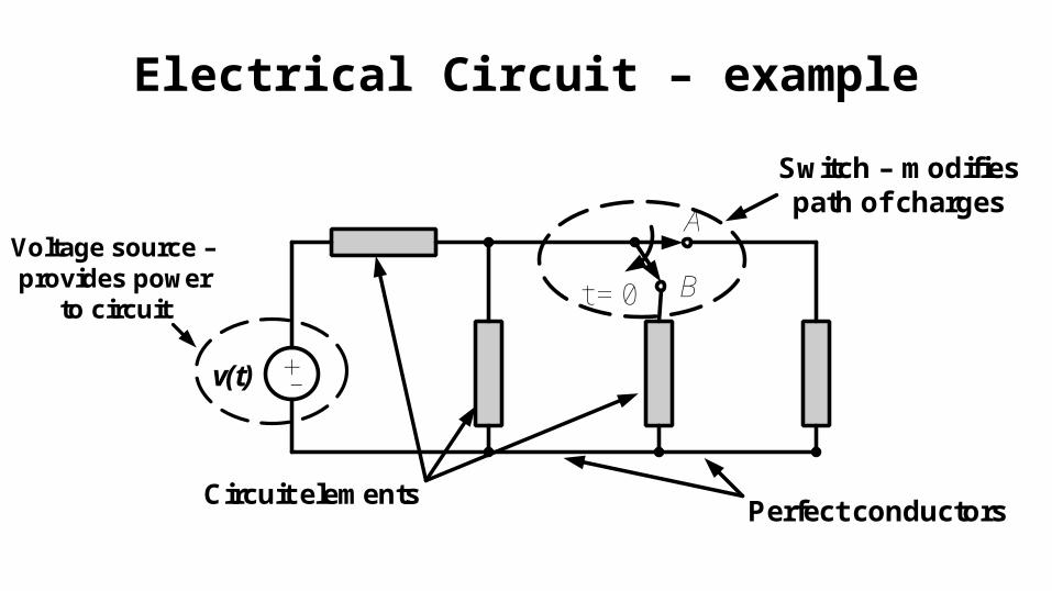
Electrical Circuit – example
+-v(t)
t = 0
A
BVoltage source – provides power
to circuit
Switch – modifies path of charges
Circuit elementsPerfect conductors
Types of Circuit Elements• Circuit components are generally classified as
control elements, passive elements, and active elements• Control Elements – direct and modify the current (e.g.
switches)• Passive Elements – total energy delivered to the element
by the rest of the circuit is nonnegative (e.g. resistors, capacitors, inductors)
• Active Elements – can provide energy to the circuit (e.g. batteries, generators)
Control Elements
• Examples:• Switches and transistors (MOSFETs, BJTs)• We will present only switches here – MOSFETs and BJTs
will be introduced in a later lecture
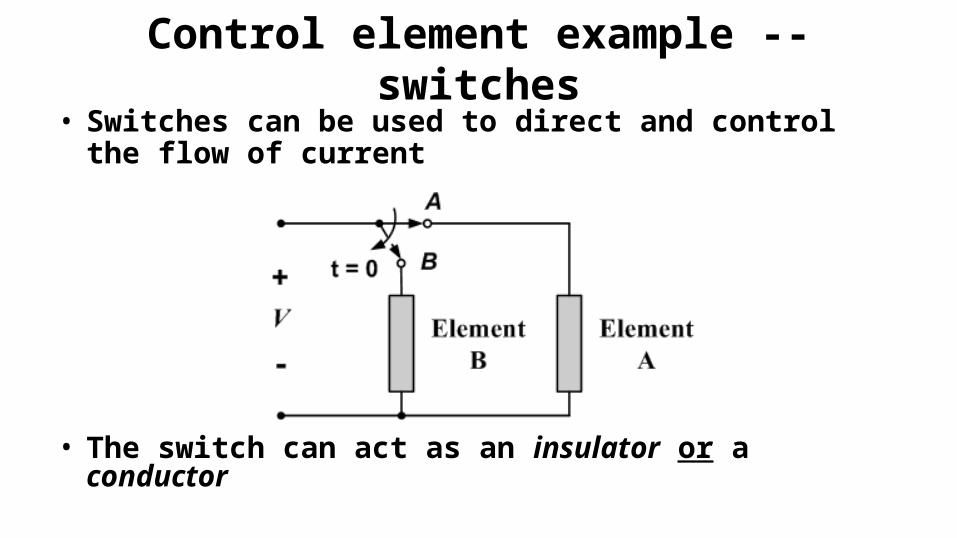
Control element example -- switches• Switches can be used to direct and control the flow
of current
• The switch can act as an insulator or a conductor
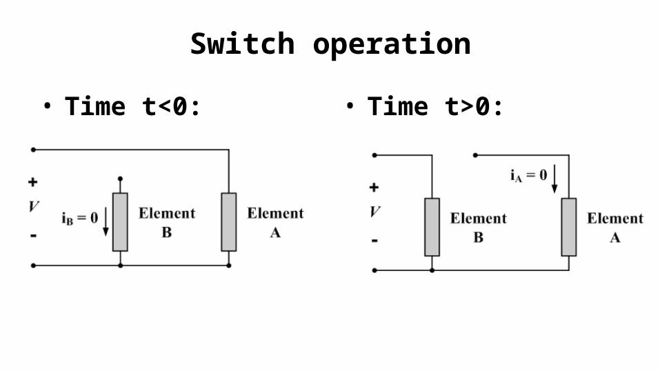
Switch operation
• Time t<0: • Time t>0:
Power Supplies
• Power supplies provide a source of electrical power
• The power source is typically a non-electrical process• Electro-mechanical sources: generators typically convert a
rotational motion to electrical power by moving magnets relative to one another. The rotational motion is induced by mechanical means, such as flowing fluid through a turbine.
• Chemical sources: batteries convert energy created by a chemical reaction to electrical energy
• Piezoelectric materials produce a voltage when they are deformed• Solar cells convert light to electrical energy
Conceptual types of power supplies
• Power supplies can be modeled in a number of ways:
• Voltage, current sources
• Independent, dependent sources
• Ideal and non-ideal sources
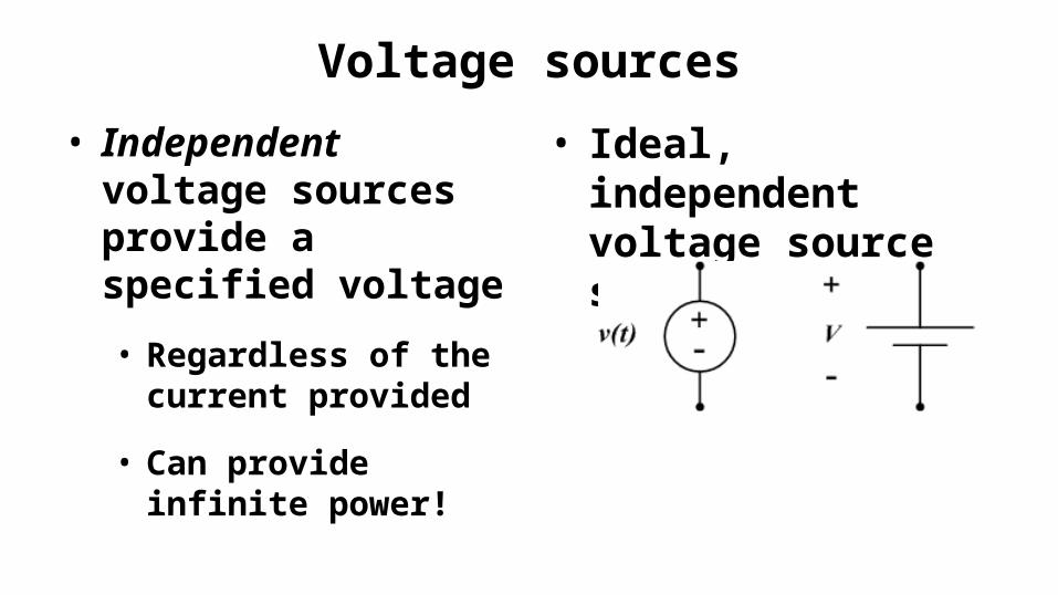
Voltage sources
• Independent voltage sources provide a specified voltage
• Regardless of the current provided
• Can provide infinite power!
• Ideal, independent voltage source symbols:
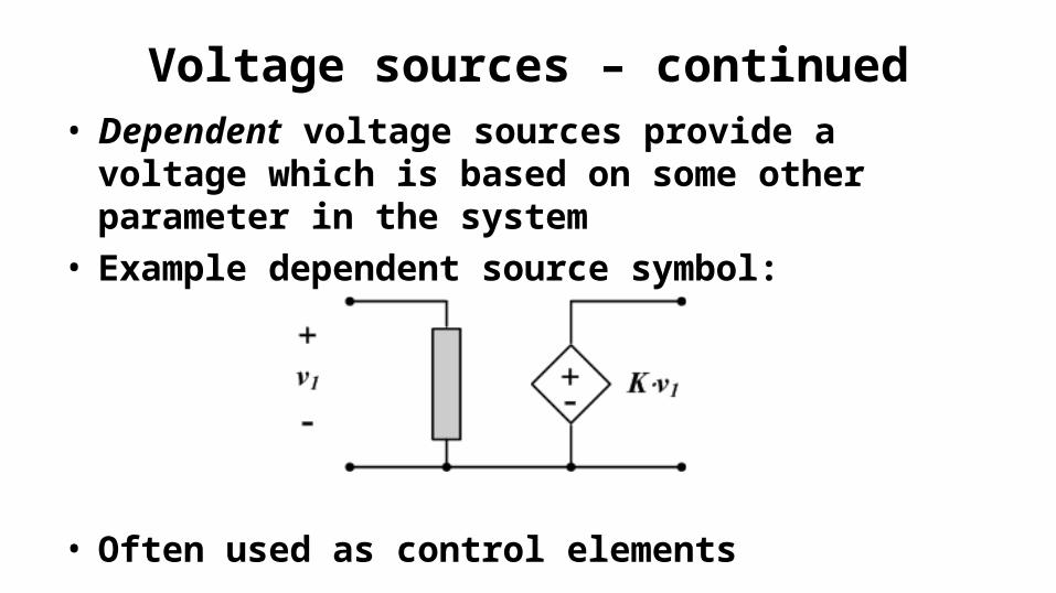
Voltage sources – continued• Dependent voltage sources provide a voltage which
is based on some other parameter in the system• Example dependent source symbol:
• Often used as control elements
Current sources
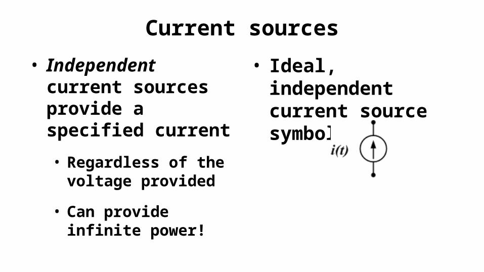
• Independent current sources provide a specified current
• Regardless of the voltage provided
• Can provide infinite power!
• Ideal, independent current source symbol:
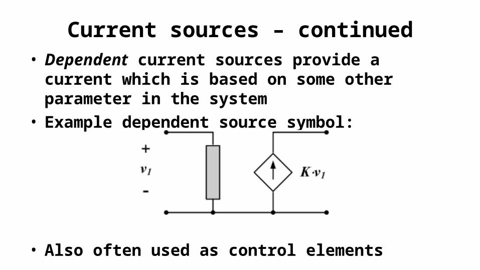
Current sources – continued• Dependent current sources provide a current which
is based on some other parameter in the system• Example dependent source symbol:
• Also often used as control elements
Common types of source signals
• Time-varying signals
• DC (Direct Current) signals• Constant with time
• AC (Alternating Current)• Vary sinusoidally with
time
Passive Circuit Elements
• Examples:• Resistors
• Capacitors
• Inductors
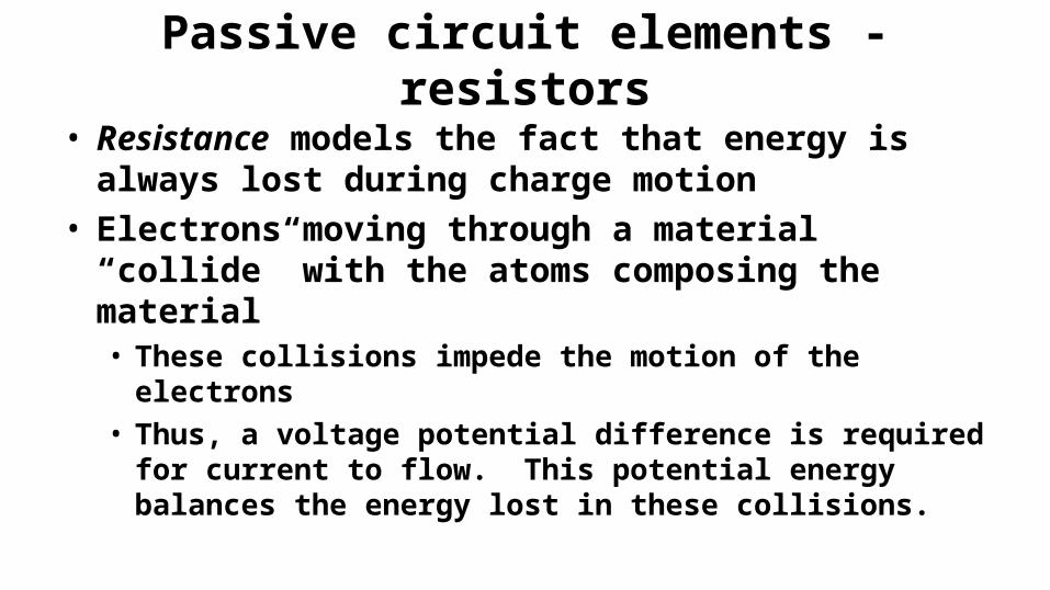
Passive circuit elements - resistors
• Resistance models the fact that energy is always lost during charge motion
• Electrons moving through a material “collide” with the atoms composing the material• These collisions impede the motion of the electrons• Thus, a voltage potential difference is required for
current to flow. This potential energy balances the energy lost in these collisions.
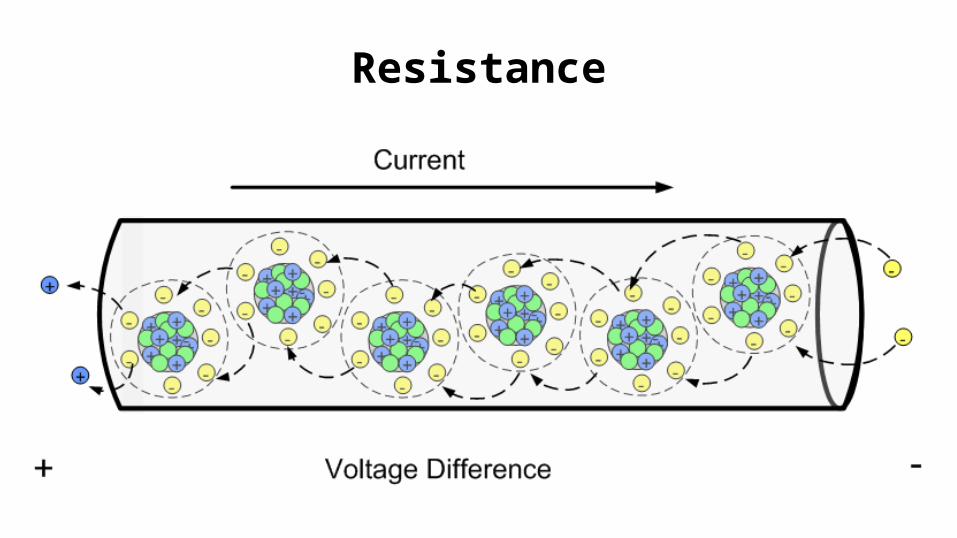
Resistance
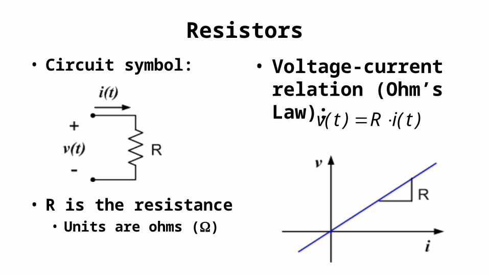
Resistors• Circuit symbol:
• R is the resistance• Units are ohms ()
• Voltage-current relation (Ohm’s Law):
)t(iR)t(v
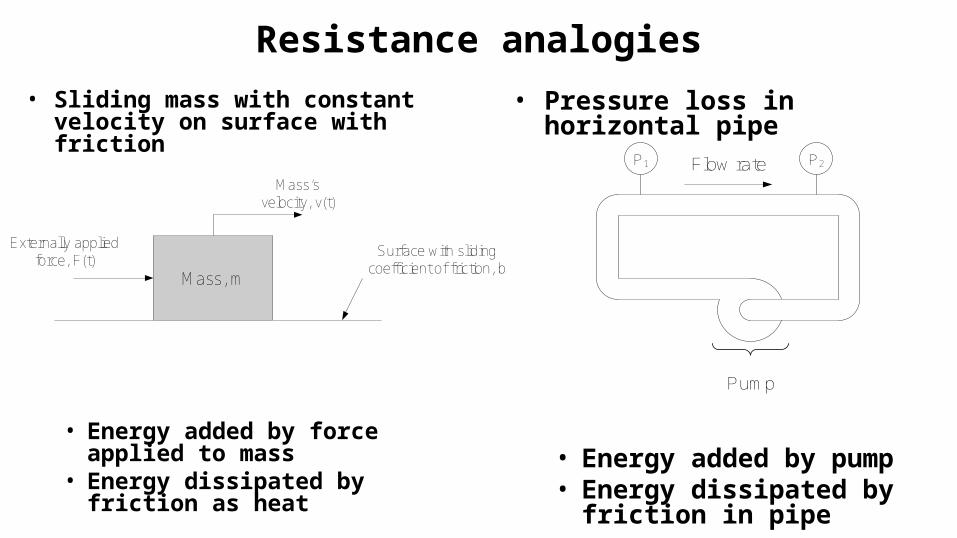
Resistance analogies• Sliding mass with constant
velocity on surface with friction
• Energy added by force applied to mass
• Energy dissipated by friction as heat
• Pressure loss in horizontal pipe
• Energy added by pump• Energy dissipated by
friction in pipe
Mass, m
Surface with sliding coefficient of friction, b
Mass’svelocity, v(t)
Externally applied force, F(t)
P1 P2
Pump
Flow rate
• Note that, in the two previous cases, none of the energy being supplied to the system is stored. The energy supplied by the force and by the pump are dissipated by the friction as heat. The kinetic and potential energies in the systems are not changing.– Resistance is purely and energy dissipation
mechanism
• Demos:– Show types of resistors (power resistor, low power resistor)– Apply voltage to power resistor, measure current. Calculate power. Note that
power resistor heats up as power dissipation increases.– Apply voltage to low power, high-resistance resistor. Calculate power
dissipation.– Apply voltage to low power, low-resistance resistor. Calculate power
dissipation, burn out resistor.
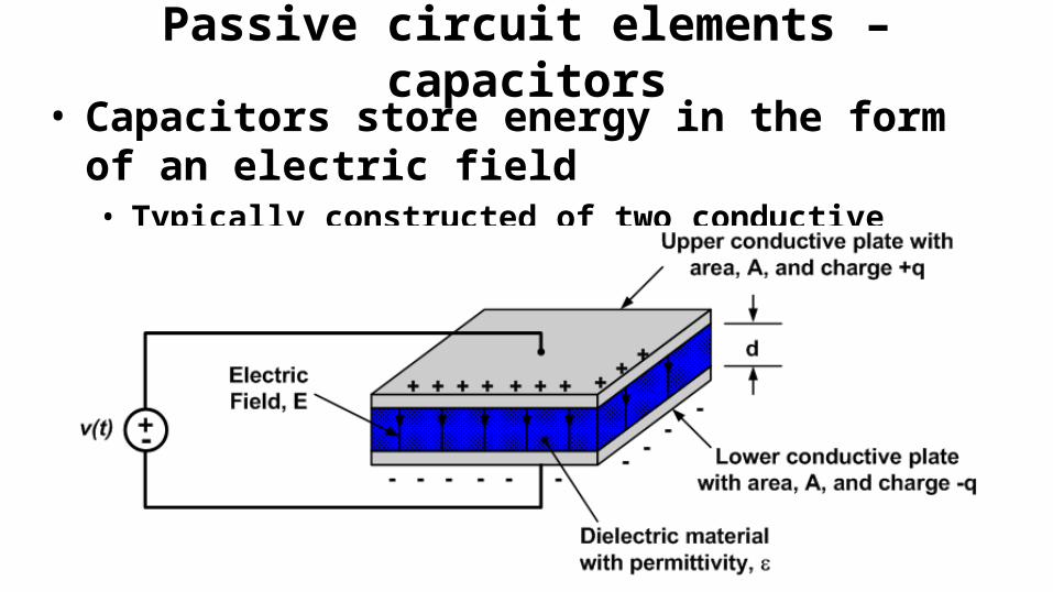
Passive circuit elements – capacitors• Capacitors store energy in the form of an electric field
• Typically constructed of two conductive materials separated by a non-conductive (dielectric) material
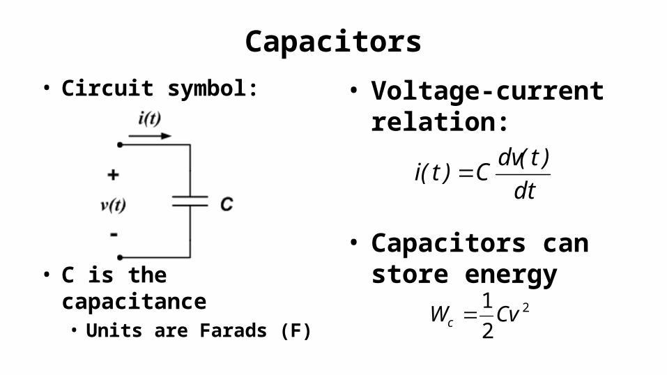
Capacitors• Circuit symbol:
• C is the capacitance• Units are Farads (F)
• Voltage-current relation:
• Capacitors can store energy
dt
)t(dvC)t(i
2
2
1CvWc
Capacitors
• Notes:• Capacitors can store energy• The voltage-current relation is a differential equation• Capacitance limits rate of change of voltage • If the voltage is constant, the current is zero and the
capacitor looks like an open-circuit
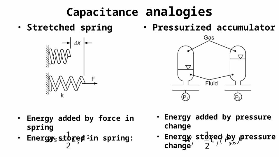
Capacitance analogies• Stretched spring
• Energy added by force in spring• Energy stored in spring:
• Pressurized accumulator
• Energy added by pressure change• Energy stored by pressure change
2
2
1FCWs S 2
2
1)P(CW gasff
• Demos:– Show types of capacitors, note sizes– Demo of energy storage with Bob Olsen’s super-capacitor/wheel device– Analogous systems:
• Stretched spring• Toilet tank
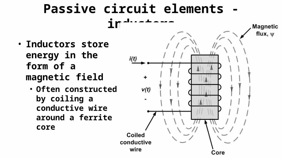
Passive circuit elements - inductors
• Inductors store energy in the form of a magnetic field• Often constructed
by coiling a conductive wire around a ferrite core
• Demo: Simple electromagnet
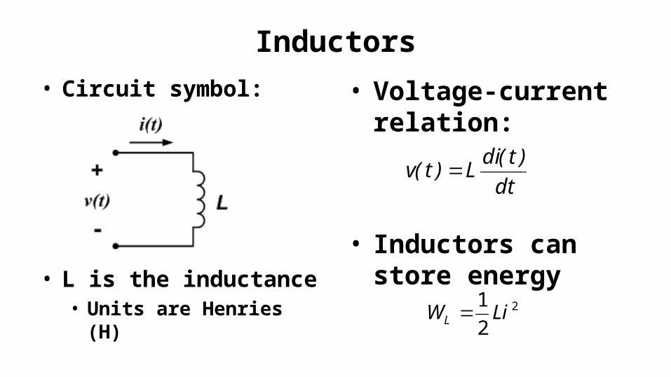
Inductors• Circuit symbol:
• L is the inductance• Units are Henries (H)
• Voltage-current relation:
• Inductors can store energy
dt
)t(diL)t(v
2
2
1LiWL
Inductors
• Notes:• Inductors can store energy• The voltage-current relation is a differential equation• If the current is constant, the voltage difference is zero
and the inductor looks like a perfect conductor
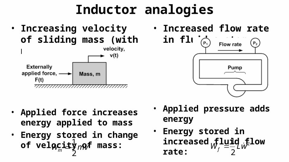
Inductor analogies• Increasing velocity of sliding
mass (with no friction)
• Applied force increases energy applied to mass
• Energy stored in change of velocity of mass:
• Increased flow rate in fluid system
• Applied pressure adds energy• Energy stored in increased fluid
flow rate:
2
2
1mvWm 2
2
1wLW f
• Demo:– Electromagnet to illustrate magnetic field– Show practical inductors– Analogies:
• Sliding mass• Slug of moving fluid


![G7 - Practical Circuits 1 G7 - PRACTICAL CIRCUITS [3 exam question - 3 groups] G7A - Power supplies; schematic symbols G7B - Digital circuits; amplifiers](https://img.pdfslide.net/doc/110x75/56649e855503460f94b86f19/g7-practical-circuits-1-g7-practical-circuits-3-exam-question-3-groups.jpg)