Embed Size (px)
Citation preview

Alpbach Summer School 2011“Star Formation across the Universe”
LectureMission and System Design
Peter Falkner (ESA)20 July 2011
P. Falkner -2-
Contents
1. Mission Design Process
2. Launcher
3. Orbits & Environment
4. Spacecraft Subsystems
5. Operations
6. Programmatics (Cost, Risk, Schedule)
P. Falkner -3-
Space Mission Elements
Orbit - Konstellation
Launcher
Spacecraft
Payload
SpaceMission
Ground Station
Mission Operation
Data Center
P. Falkner -4-
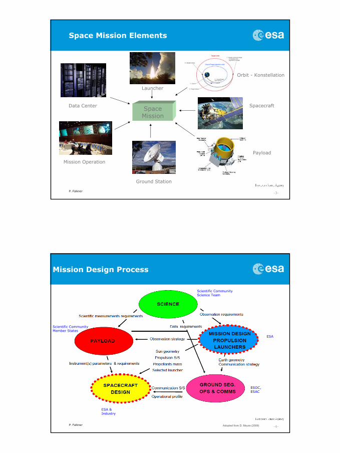
Mission Design Process
Adopted from D. Moura (2009)
Scientific CommunityScience Team
Scientific CommunityMember States
ESA
ESOC,ESAC
ESA &Industry

P. Falkner -5-
System Design / End-to-End view
Study Phase 0:
• Analysis of Mission Objectives
• Analysis of Mission Constraints
• Definition of Science Requirements
• Definition of Mission Architecture (s)
• Definition of payload / performance
• Analysis of Environment
• Iteration / Trade phase
• Cost, Risk, Schedule, Technology Development
Goal:
• feasible mission profile
• satisfying requirements and constraints
SMAD, p. 13 Space Mission Architecture
P. Falkner -6-
Launcher
– Provides access to Space– Main trade: Performance/Cost (end-to-end view)– Possibility of sharing launch (e.g. Herschel / Planck)– Trade: direct transfer vs. optimisation of launcher insertion orbit
(spacecraft design dependent)– Attention (!): launch environment/constraints (incl. launch site)
– Soyuz Fregat-2B (70 M€), Ariane 5 ECA (150M€), VEGA (35M€)
– Performance: SF-2B ~ 4900 kg @ SSO 650km SF-2B ~ 2150 kg to L2A5 ~ 8000 kg @ SSO 800 km
– For performance => see launcher user manuals (web)
Ariane-5 ECBGTO
~12000 kg
P. Falkner -7-
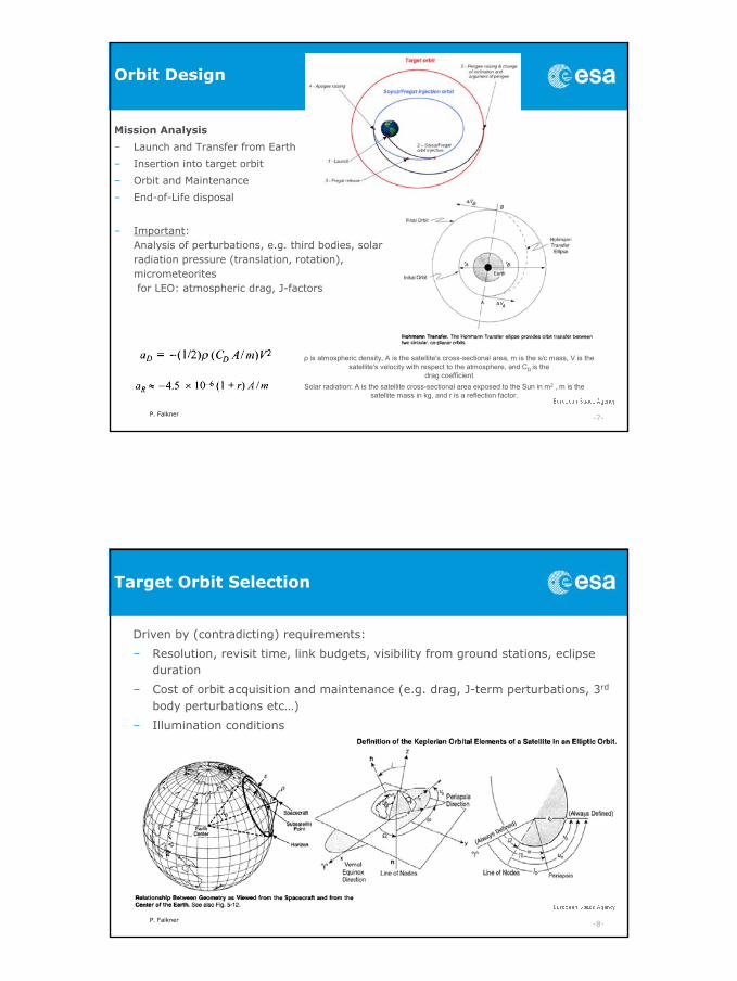
Orbit Design
Mission Analysis
– Launch and Transfer from Earth
– Insertion into target orbit
– Orbit and Maintenance
– End-of-Life disposal
– Important: Analysis of perturbations, e.g. third bodies, solar radiation pressure (translation, rotation), micrometeoritesfor LEO: atmospheric drag, J-factors
Solar radiation: A is the satellite cross-sectional area exposed to the Sun in m2 , m is the satellite mass in kg, and r is a reflection factor.
ρ is atmospheric density, A is the satellite's cross-sectional area, m is the s/c mass, V is the satellite's velocity with respect to the atmosphere, and CD is the
drag coefficient
P. Falkner -8-
Target Orbit Selection
Driven by (contradicting) requirements:
– Resolution, revisit time, link budgets, visibility from ground stations, eclipse duration
– Cost of orbit acquisition and maintenance (e.g. drag, J-term perturbations, 3rd
body perturbations etc…)
– Illumination conditions
P. Falkner -9-
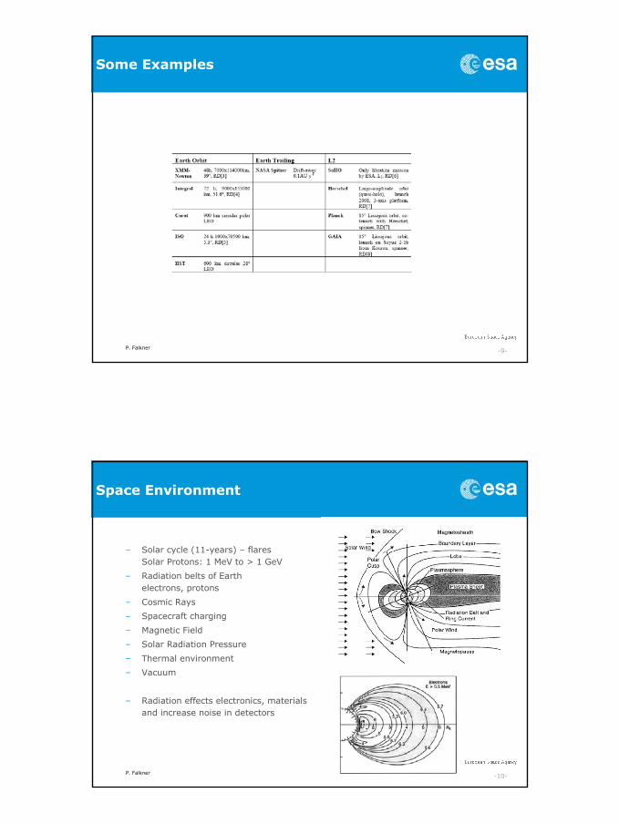
Some Examples
P. Falkner -10-
Space Environment
– Solar cycle (11-years) – flaresSolar Protons: 1 MeV to > 1 GeV
– Radiation belts of Earth electrons, protons
– Cosmic Rays
– Spacecraft charging
– Magnetic Field
– Solar Radiation Pressure
– Thermal environment
– Vacuum
– Radiation effects electronics, materials and increase noise in detectors
P. Falkner -11-
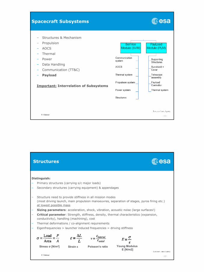
Spacecraft Subsystems
– Structures & Mechanism
– Propulsion
– AOCS
– Thermal
– Power
– Data Handling
– Communication (TT&C)
– Payload
Important: Interrelation of Subsystems
P. Falkner -12-
Structures
Distinguish:
– Primary structures (carrying s/c major loads)
– Secondary structures (carrying equipment) & appendages
– Structure need to provide stiffness in all mission modes(most driving launch, main propulsion manoeuvres, separation of stages, pyros firing etc.) at lowest possible mass
– Sizing parameters: acceleration, shock, vibration, acoustic noise (large surfaces!)
– Critical parameter: Strength, stiffness, density, thermal characteristics (expansion, conductivity), handling (machining), cost
– Thermal deformations / co-alignment requirements
– Eigenfrequencies > launcher induced frequencies = driving stiffness
Stress σ [N/m2] Strain ε Young Modulus E [N/m2]
Poisson’s ratio
P. Falkner -13-
Mechanism
Moving parts:– Reliability is critical (lubrication in space, long storage, thermal range)– Introduce vibrations
Examples:– Launch lock mechanism (hold down release mechanism HDRM)– Deployment of structure, appendages and booms
(e.g. solar panel, sun shield, antennae, …)– Separation mechanism (separation of stages, multiple s/c,..)– Pointing mechanism (e.g. payload, HG-antenna, panels)– Reaction wheels– Deployable instrument covers
Mechanism are a source of mechanical noise
– Motors and gears: e.g. Maxon– Frangibolt® Actuator – http://www.tiniaerospace.com/fbt/fbfc3-20-16sr2.html
HDRM
P. Falkner -14-
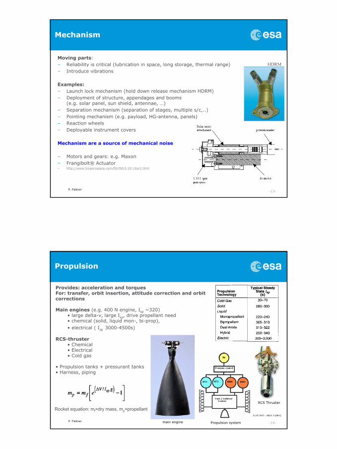
Propulsion
Provides: acceleration and torquesFor: transfer, orbit insertion, attitude correction and orbit corrections
Main engines (e.g. 400 N engine, Isp ~320)• large delta-v, large Isp, drive propellant need• chemical (solid, liquid mon-, bi-prop), • electrical ( Isp 3000-4500s)
RCS-thruster• Chemical• Electrical• Cold gas
• Propulsion tanks + pressurant tanks• Harness, piping
Rocket equation: mf=dry mass, mp=propellant
main engine
RCS Thruster
Propulsion system
P. Falkner -15-
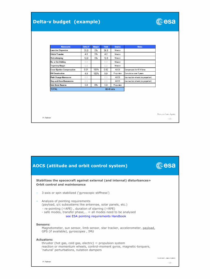
Delta-v budget (example)
P. Falkner -16-
AOCS (attitude and orbit control system)
Stabilizes the spacecraft against external (and internal) disturbances+Orbit control and maintenance
– 3-axis or spin stabilized (‘gyroscopic stiffness’)
– Analysis of pointing requirements (payload, s/c subsystems like antennae, solar panels, etc.)- re-pointing ( APE) , duration of starring ( RPE)- safe modes, transfer phase,… all modes need to be analysed
see ESA pointing requirements Handbook
Sensors:Magnetometer, sun sensor, limb sensor, star tracker, accelerometer, payload,GPS (if available), gyroscopes , IMU
Actuators:thruster (hot gas, cold gas, electric) propulsion systemreaction or momentum wheels, control-moment gyros, magnetic-torquers, ‘natural’ perturbations, nutation dampers
P. Falkner -17-
Thermal
Controls spacecraft thermal environment (within operational, non-operational ranges) in various mission modes:
– Launch, transfer, science mode, safe mode, eclipse, etc…
– Driven by equipment and payload requirements– Need careful analysis of all modes (internal dissipation and external input) under various
aspect angles.
Sensors: temperature sensors
Control Components:– Coatings, MLI, paint, radiators, sun shields, foam, heat pipes, optical reflectors, louvers,
fillers, thermal insulators, cooler, cold plates, phase change devices, electrical heaters & thermostats, RHU’s,….
– Using of emission (ε), absorption (α) values
– Requires: Geometrical Mathematical Model (GMM) and Thermal Mathematical Model (TMM) – e.g. ESATAN
– Need to understand the characteristics and dissipation of all s/c equipment
Attention (!) to: thermo-elastics ( co-alignment), outgasing
P. Falkner -18-
Power
Provides: electrical power to S/C bus and payloadSolar Panel (e.g. triple-Junction cell ~28-32% eff.)
• panels need to point to the sun (dependent on orbit characteristics pointing mechanism needed 1-2 DOF?)
• body mounted (typ. spinner) or panel type (3-axis)• input at Earth: 1367 W/m2 solar flux
• Batteries• Primary (up to ~300 Whr/kg) and Secondary (re-chargeable, e.g. Li-Ion ~120 Whr/kg)• Energy storage• needed for emergency (safe mode), eclipses,…
• Alternative energy sources• Nuclear Power (RTG, RHU’s, ASGR’s), …
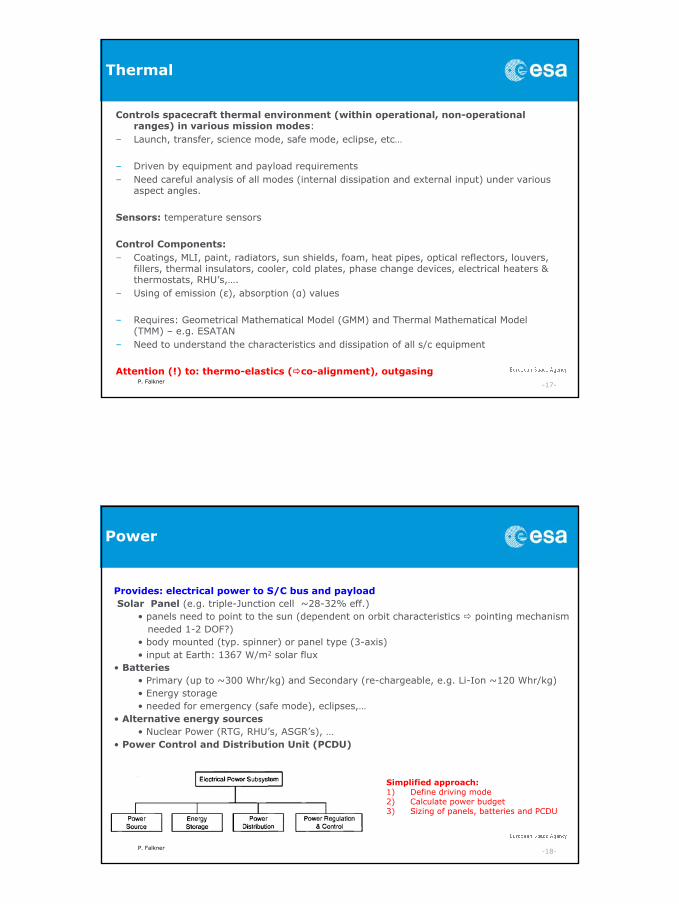
• Power Control and Distribution Unit (PCDU)
Simplified approach:1) Define driving mode2) Calculate power budget3) Sizing of panels, batteries and PCDU
P. Falkner -19-
Data Handling & Control
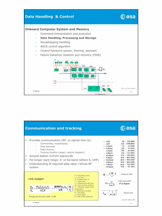
Onboard Computer System and Memory
– Command Interpretation and execution
– Data Handling, Processing and Storage
– Housekeeping handling
– AOCS control algorithm
– Control functions (power, thermal, payload)
– Failure Detection Isolation and recovery (FDIR)
P. Falkner -20-
Communication and tracking
• Provides communication (RF- or optical link) for:– Commanding, housekeeping
– Data download
– Radio-Science
– Tracking (location (range), velocity (doppler))
• Ground station to/from spacecraft
• For longer slant range: X- or Ka-band (others S, UHF)
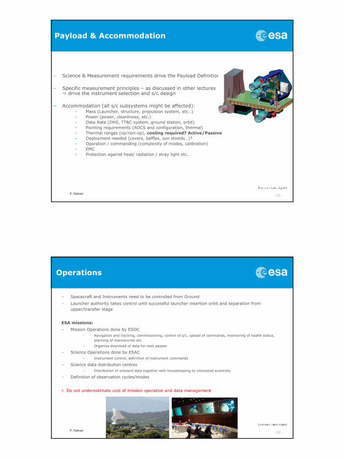
• Understanding of required data rates drives RF system
Energy per bit over noise >3 dB
P = transmitter powerLl = Line lossGt =Antenna Gain TxLs = space lossLa = transmission path lossGr = Gain receiver antennaTs = Receiver system noise temperaturek = Boltzmann constantR = data Rateλ = wave lengthS = path length (distance)
Antenna Gain
3-dB beamwidth
Space loss
Link budget:
P. Falkner -21-
Payload & Accommodation
– Science & Measurement requirements drive the Payload Definition
– Specific measurement principles – as discussed in other lectures drive the instrument selection and s/c design
– Accommodation (all s/c subsystems might be affected): – Mass (Launcher, structure, propulsion system, etc…)– Power (power, cleanliness, etc.)– Data Rate (DHS, TT&C system, ground station, orbit)– Pointing requirements (AOCS and configuration, thermal)– Thermal ranges (op/non-op), cooling required? Active/Passive– Deployment needed (covers, baffles, sun shields…)?– Operation / commanding (complexity of modes, calibration)– EMC– Protection against heat/ radiation / stray light etc.
P. Falkner -22-
Operations
– Spacecraft and Instruments need to be controlled from Ground
– Launcher authority takes control until successful launcher insertion orbit and separation from upper/transfer stage
ESA missions:
– Mission Operations done by ESOC– Navigation and tracking, commissioning, control of s/c, upload of commands, monitoring of health status,
planning of manoeuvres etc.
– Organise download of data for next passes
– Science Operations done by ESAC– Instrument control, definition of instrument commands
– Science data distribution centres– Distribution of onboard data together with housekeeping to interested scientists
– Definition of observation cycles/modes
Do not underestimate cost of mission operation and data management

P. Falkner -23-
Technology Development
• Level of technology readiness is a key system driver• Assessment of efforts required to reach flight status is difficult• Assessment done according to the table below• Non availability of Technology can be detrimental to the schedule and cost
Technology Readiness Levels (TRL):
P. Falkner -24-
Cost, Risk and Schedule
Cost estimate is very difficult !– 3 methods:
Bottom up approach, parametric analysis or by analogy with other missions– Need cost model and data base with cost info– Most difficult is the estimate on engineering cost, manpower etc.
cost of technology TRL upgrade– Cost is driven by complexity of mission
Cost at completion comprises:– Development cost– Procurement cost of the space segment (industrial cost)– Test facilities cost– Launch cost– Mission operation cost– Science operations cost (Data analysis, distribution and archiving)– Agency cost and margins– Management costs– Payload cost– …
P. Falkner -25-
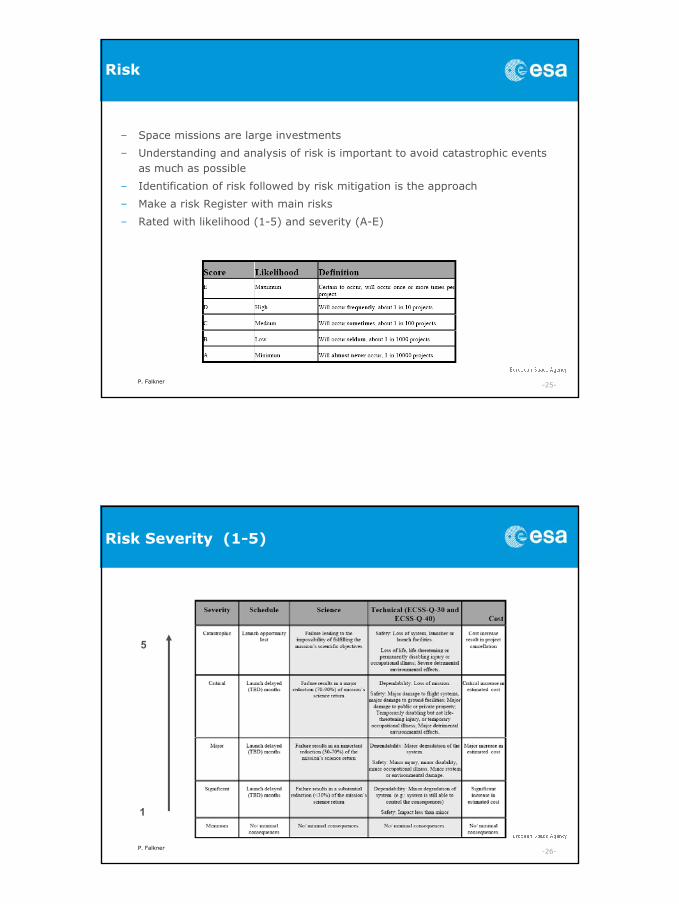
Risk
– Space missions are large investments
– Understanding and analysis of risk is important to avoid catastrophic events as much as possible
– Identification of risk followed by risk mitigation is the approach
– Make a risk Register with main risks
– Rated with likelihood (1-5) and severity (A-E)
P. Falkner -26-
Risk Severity (1-5)
1
5
P. Falkner -27-
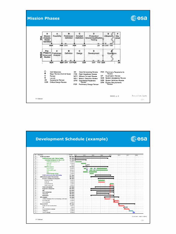
Mission Phases
SMAD, p. 8
P. Falkner -28-
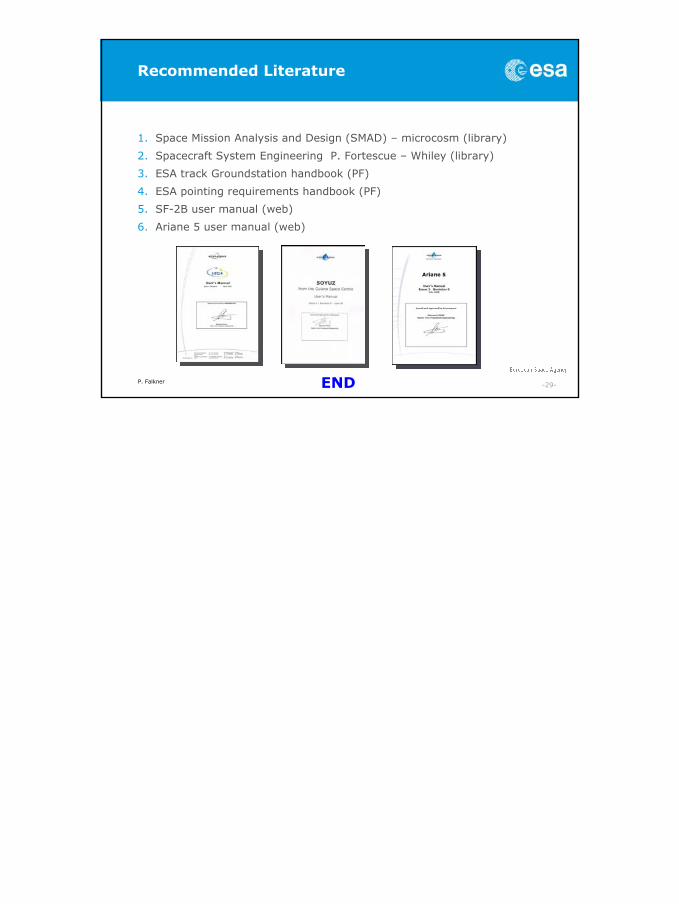
Development Schedule (example)
P. Falkner -29-
Recommended Literature
1. Space Mission Analysis and Design (SMAD) – microcosm (library)
2. Spacecraft System Engineering P. Fortescue – Whiley (library)
3. ESA track Groundstation handbook (PF)
4. ESA pointing requirements handbook (PF)
5. SF-2B user manual (web)
6. Ariane 5 user manual (web)
END