Embed Size (px)
DESCRIPTION
Introduction to Mobile Communication
Citation preview

Muhammad Ali Jinnah University, Islamabad Campus, Pakistan
© Dr. Noor M Khan
EE, MAJU Introduction to Wireless
Communications
EE/ECE6733 Cellular Mobile Communications
Week 1-2-3-4 ; Fall - 2013 1
Introduction to Wireless Communications
Lecturer: Engr. Prof. Dr. Noor M. Khan
Department of Electronic Engineering,
Muhammad Ali Jinnah University,
Islamabad Campus, Islamabad, PAKISTAN
Ph: +92 (51) 111-878787, Ext. 129 email: [email protected], [email protected]
PSTN MSC

Muhammad Ali Jinnah University, Islamabad Campus, Pakistan
© Dr. Noor M Khan
EE, MAJU Introduction to Wireless
Communications
EE/ECE6733 Cellular Mobile Communications
Week 1-2-3-4 ; Fall - 2013 2
Instructor’s Contact
Instructor: Dr. Noor M. Khan
Email: [email protected]
Phone: 051-111-878787, Ext: 129
Wireless Communications Research Lab, C-Block
Profiles:
• http://www.arwic.com/view-profile.php?id=194
• http://sc.hec.gov.pk/aphds/submit.asp?supid=2275

Muhammad Ali Jinnah University, Islamabad Campus, Pakistan
© Dr. Noor M Khan
EE, MAJU Introduction to Wireless
Communications
EE/ECE6733 Cellular Mobile Communications
Week 1-2-3-4 ; Fall - 2013 3
Research Interests
1. Wireless and Cellular Mobile Communication Systems
2. Fading Channel Modeling and Characterization
3. Smart Antennas and MIMO systems
4. Adaptive Signal Processing
5. Adaptive Multiuser Detection
6. CDMA Systems
7. Wireless Sensor Networks
8. Wireless LANs
9. Mobile Robot Navigation

Muhammad Ali Jinnah University, Islamabad Campus, Pakistan
© Dr. Noor M Khan
EE, MAJU Introduction to Wireless
Communications
EE/ECE6733 Cellular Mobile Communications
Week 1-2-3-4 ; Fall - 2013 4
Contents • Telephone history
• Types of radio communication systems – Cellular systems
– Cordless Systems
– Paging Systems
– Satellite Systems
– Wireless LANs
– Broadcast Systems
– Bluetooth
– Design challenges
Muhammad Ali Jinnah University, Islamabad Campus, Pakistan
© Dr. Noor M Khan
EE, MAJU Introduction to Wireless
Communications
EE/ECE6733 Cellular Mobile Communications
Week 1-2-3-4 ; Fall - 2013 5
Contents (Contd.) • History of Cellular Mobile Comm. Systems
• Basic Concepts andTerminology in Cellular
Mobile Systems
– Base station, Mobile station, Handoff

Muhammad Ali Jinnah University, Islamabad Campus, Pakistan
© Dr. Noor M Khan
EE, MAJU
Wireless Communications
Introduction to Wireless
Communications
EE/ECE6733 Cellular Mobile Communications
Week 1-2-3-4 ; Fall - 2013 6
• Multimedia wireless Communications at any Time and Anywhere
• Brief history
– Ancient Systems: Smoke Signals, Fire Signals, Carrier Pigeons
– Radio invented in the 1880s by Marconi
– Many sophisticated military radio systems were developed during and after WW2
– Cellular has enjoyed exponential growth since 1988, with more than 2 billion users worldwide today
– Ignited the recent wireless revolution, 1980-2010
– Growth rate tapering off (World wide) but may increase (in Pakistan)
– Is there any future for wireless?
Muhammad Ali Jinnah University, Islamabad Campus, Pakistan
© Dr. Noor M Khan
EE, MAJU Introduction to Wireless
Communications
EE/ECE6733 Cellular Mobile Communications
Week 1-2-3-4 ; Fall - 2013 7
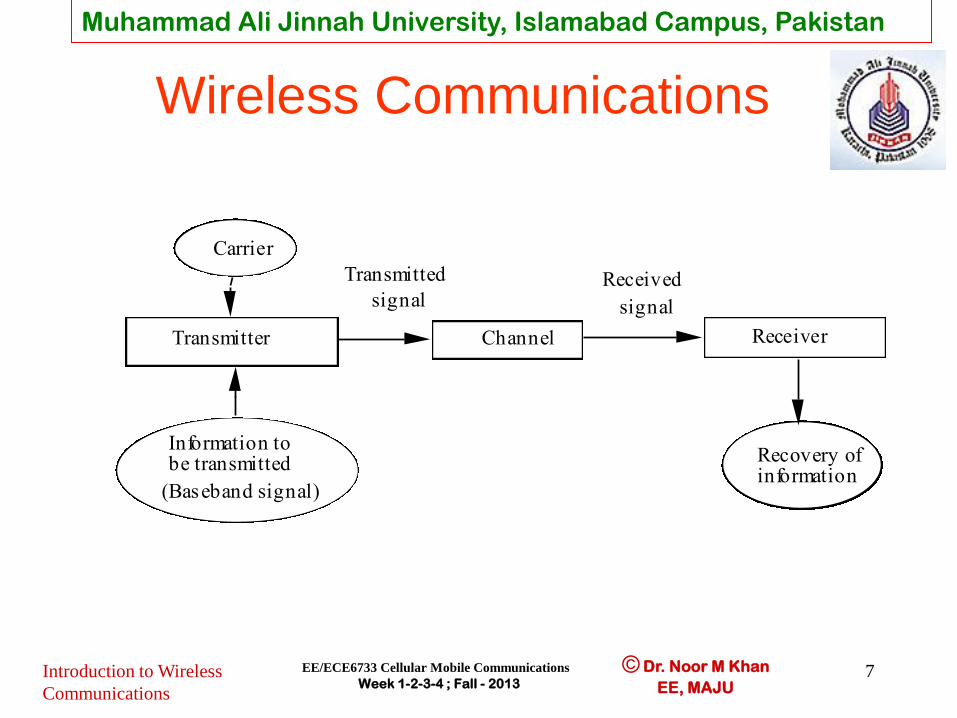
Wireless Communications
Transmitter
Carrier
Information to be transmitted
(Baseband signal)
Transmitted
signal
Channel
Received
signal
Receiver
Recovery of information

Muhammad Ali Jinnah University, Islamabad Campus, Pakistan
© Dr. Noor M Khan
EE, MAJU Introduction to Wireless
Communications
EE/ECE6733 Cellular Mobile Communications
Week 1-2-3-4 ; Fall - 2013 8
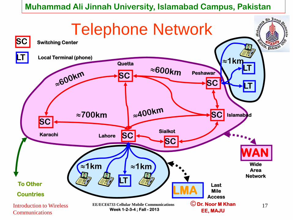
Telephone Network
SC
SC
SC
SC
SC
SC
LT
LT
Karachi
Quetta
Peshawar
Lahore Sialkot
Islamabad
SC Switching Center
LT Local Terminal (phone)
LT
WAN
LMA
Wide
Area
Network
Last
Mile
Access
To Other
Countries
Muhammad Ali Jinnah University, Islamabad Campus, Pakistan
© Dr. Noor M Khan
EE, MAJU Introduction to Wireless
Communications
EE/ECE6733 Cellular Mobile Communications
Week 1-2-3-4 ; Fall - 2013 9
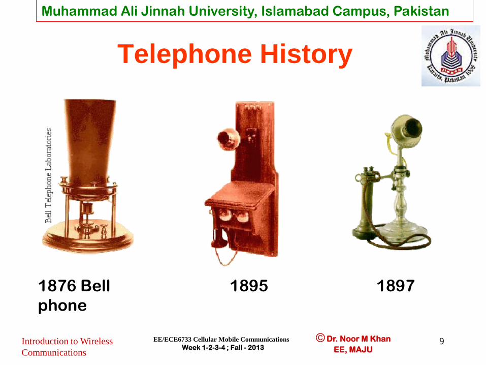
Telephone History
1876 Bell
phone
1895 1897

Muhammad Ali Jinnah University, Islamabad Campus, Pakistan
© Dr. Noor M Khan
EE, MAJU Introduction to Wireless
Communications
EE/ECE6733 Cellular Mobile Communications
Week 1-2-3-4 ; Fall - 2013 10
Telephone History
1904 1927 1937
Muhammad Ali Jinnah University, Islamabad Campus, Pakistan
© Dr. Noor M Khan
EE, MAJU Introduction to Wireless
Communications
EE/ECE6733 Cellular Mobile Communications
Week 1-2-3-4 ; Fall - 2013 11
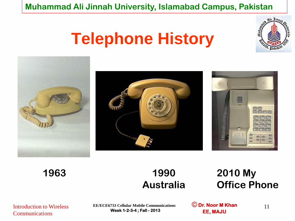
Telephone History
1963 1990
Australia
2010 My
Office Phone

Muhammad Ali Jinnah University, Islamabad Campus, Pakistan
© Dr. Noor M Khan
EE, MAJU
Wireless Systems: Range Comparison
Introduction to Wireless
Communications
EE/ECE6733 Cellular Mobile Communications
Week 1-2-3-4 ; Fall - 2013 12
Satellite
Links
SW
Radio
MW
Radio FM
Radio
Mobile
Telephony WLANs Blueooth
1,000 Km 100 Km 10 Km 1 Km 100 m 10 m 1 m

Muhammad Ali Jinnah University, Islamabad Campus, Pakistan
© Dr. Noor M Khan
EE, MAJU
US Frequency Bands
Introduction to Wireless
Communications
EE/ECE6733 Cellular Mobile Communications
Week 1-2-3-4 ; Fall - 2013 13
Band Frequency range
UHF ISM 902-928 MHz
S-Band 2-4 GHz
S-Band ISM 2.4-2.5 GHz
C-Band 4-8 GHz
C-Band satellite downlink 3.7-4.2 GHz
C-Band Radar (weather) 5.25-5.925 GHz
C-Band ISM 5.725-5.875 GHz
C-Band satellite uplink 5.925-6.425 GHz
X-Band 8-12 GHz
X-Band Radar (police/weather) 8.5-10.55 GHz

Muhammad Ali Jinnah University, Islamabad Campus, Pakistan
© Dr. Noor M Khan
EE, MAJU Introduction to Wireless
Communications
EE/ECE6733 Cellular Mobile Communications
Week 1-2-3-4 ; Fall - 2013 14
• Geographic region divided into cells • Frequencies/timeslots/codes reused at spatially-separated locations.
• Co-channel interference between same color cells.
• Base stations/MTSOs coordinate handoff and control functions
• Shrinking cell size increases capacity, as well as networking burden
BASE
STATIO
N MTSO
(MSC)
Cellular Systems: Reuse channels to maximize capacity

Muhammad Ali Jinnah University, Islamabad Campus, Pakistan
© Dr. Noor M Khan
EE, MAJU
Cellular Systems
Introduction to Wireless
Communications
EE/ECE6733 Cellular Mobile Communications
Week 1-2-3-4 ; Fall - 2013 15
Satellite
Macrocell Microcell
Urban In-Building
Picocell
Global
Suburban
Basic Terminal
PDA Terminal
Audio/Visual Terminal

Muhammad Ali Jinnah University, Islamabad Campus, Pakistan
© Dr. Noor M Khan
EE, MAJU
Cellular Networks
Introduction to Wireless
Communications
EE/ECE6733 Cellular Mobile Communications
Week 1-2-3-4 ; Fall - 2013 16
BS BS
MTSO/MSC PSTN
MTSO/MSC
BS
Peshawar
Karachi Internet
Muhammad Ali Jinnah University, Islamabad Campus, Pakistan
© Dr. Noor M Khan
EE, MAJU Introduction to Wireless
Communications
EE/ECE6733 Cellular Mobile Communications
Week 1-2-3-4 ; Fall - 2013 17
Telephone Network
SC
SC
SC
SC
SC
SC
LT
LT
Karachi
Quetta
Peshawar
Lahore Sialkot
Islamabad
SC Switching Center
LT Local Terminal (phone)
LT
WAN
LMA
Wide
Area
Network
Last
Mile
Access
To Other
Countries

Muhammad Ali Jinnah University, Islamabad Campus, Pakistan
© Dr. Noor M Khan
EE, MAJU Introduction to Wireless
Communications
EE/ECE6733 Cellular Mobile Communications
Week 1-2-3-4 ; Fall - 2013 18
Cordless System
• Cordless telephone (CT) is a
communication system using radio waves to
connect portable handset to a dedicated
fixed port (base station) which is connected
to PSTN as a normal telephone line (using
ordinary telephone numbers)
• CT provides limited range and mobility in
the vicinity of the base station (100 m)

Muhammad Ali Jinnah University, Islamabad Campus, Pakistan
© Dr. Noor M Khan
EE, MAJU Introduction to Wireless
Communications
EE/ECE6733 Cellular Mobile Communications
Week 1-2-3-4 ; Fall - 2013 19
Cordless Telephone
Public
Switched
Telephone
Network
(PSTN) Fixed
Port
Wireless
link
Cordless
Handset
Muhammad Ali Jinnah University, Islamabad Campus, Pakistan
© Dr. Noor M Khan
EE, MAJU Introduction to Wireless
Communications
EE/ECE6733 Cellular Mobile Communications
Week 1-2-3-4 ; Fall - 2013 20
Paging
• Paging systems are wireless
communication systems that send brief
messages to a subscriber
• A message is sent to a paging subscriber via
the paging system access number by a
telephone keypad or modem
• The issued message is called a page

Muhammad Ali Jinnah University, Islamabad Campus, Pakistan
© Dr. Noor M Khan
EE, MAJU Introduction to Wireless
Communications
EE/ECE6733 Cellular Mobile Communications
Week 1-2-3-4 ; Fall - 2013 21
Paging
Public
Switched
Telephone
Network
Paging
Control
Center
Paging
Terminal
Paging
Terminal
Paging
Terminal
Landline Link
Landline Link
Satellite Link
City 1
City 2
City N

Muhammad Ali Jinnah University, Islamabad Campus, Pakistan
© Dr. Noor M Khan
EE, MAJU Introduction to Wireless
Communications
EE/ECE6733 Cellular Mobile Communications
Week 1-2-3-4 ; Fall - 2013 22
Satellite Communication
System • In a geostationary satellite system, a message signal is transmitted
from an earth station via an uplink to a satellite, amplified in a
transponder on board the satellite, and then retransmitted via
downlink to another earth station.

Muhammad Ali Jinnah University, Islamabad Campus, Pakistan
© Dr. Noor M Khan
EE, MAJU Introduction to Wireless
Communications
EE/ECE6733 Cellular Mobile Communications
Week 1-2-3-4 ; Fall - 2013 23
Satellite Communication
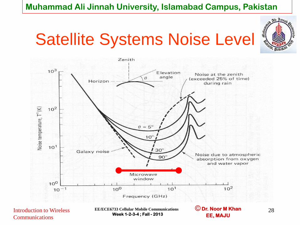
System • The most popular frequency band for satellite communications is
6GHz for the uplink and 4GHz for the downlink for the following
reasons:
– Relatively inexpensive microwave equipment
– Low attenuation due to rainfall (primary cause of signal
degradation)
– Insignificant sky background noise (galactic, solar and terrestrial
sources produce low noise in the region 1-10GHz)
• This (6/4GHz) band is used for terrestrial microwave links
• Second generation of satellites use 14/12 GHz band
• 14/12 GHz band requires smaller antennas than 6/4GHz band.

Muhammad Ali Jinnah University, Islamabad Campus, Pakistan
© Dr. Noor M Khan
EE, MAJU Introduction to Wireless
Communications
EE/ECE6733 Cellular Mobile Communications
Week 1-2-3-4 ; Fall - 2013 24
Wireless Local Area Networks (WLANs)
WLANs connect “local” computers (100m range)
Breaks data into packets
Channel access is shared (random access)
Backbone Internet provides best-effort service
Poor performance in some apps (e.g. video)
01011011
Internet
Access
Point
0101 1011

Muhammad Ali Jinnah University, Islamabad Campus, Pakistan
© Dr. Noor M Khan
EE, MAJU Introduction to Wireless
Communications
EE/ECE6733 Cellular Mobile Communications
Week 1-2-3-4 ; Fall - 2013 25
Wireless LAN Standards • 802.11b (Earlier Generation)
– Standard for 2.4GHz ISM band (80 MHz) – Frequency hopped spread spectrum – 1.6-10 Mbps, 500 ft range
• 802.11a (Emerging Generation) – Standard for 5GHz band (300 MHz) – OFDM with time division – 20-70 Mbps, variable range
• 802.11g (Current Generation) – Standard in 2.4 GHz and 5 GHz bands – OFDM – Speeds up to 54 Mbps
Now, almost
all available
WLAN
Cards
have all 3
standards

Muhammad Ali Jinnah University, Islamabad Campus, Pakistan
© Dr. Noor M Khan
EE, MAJU Introduction to Wireless
Communications
EE/ECE6733 Cellular Mobile Communications
Week 1-2-3-4 ; Fall - 2013 26
Wireless LAN Standards • 802.11n, ac (Next Generations)
– Standard in 2.4 GHz and 5 GHz bands with 20/40MHz – MIMO-OFDM – Speeds up to 600 Mbps

Muhammad Ali Jinnah University, Islamabad Campus, Pakistan
© Dr. Noor M Khan
EE, MAJU
WiFi Standards Comparison Table
Introduction to Wireless
Communications
EE/ECE6733 Cellular Mobile Communications
Week 1-2-3-4 ; Fall - 2013 27
802.11b 802.11g 802.11a 802.11n
IEEE Ratified 1999 2001 1999 2008
Frequency 2.4GHz 2.4GHz 5GHz 2.4GHz 5GHz
Non-overlapping
Channels
3 3 12 3 12
Baseline Bandwidth Per
Channel
11Mbps 54Mbps 54Mbps 65Mbps 65Mbps
Number of Spatial
Streams
1 1 1 2, 3* or 4* 2, 3* or 4*
Channel Bonding No No No No Yes
Max Bandwidth Per
Channel
11Mbps 54Mbps 54Mbps 130Mbps 270Mbps
Ref: Wireless Standards Comparison Table, Available Online at http://www.air-stream.org.au/wireless_standards
Muhammad Ali Jinnah University, Islamabad Campus, Pakistan
© Dr. Noor M Khan
EE, MAJU Introduction to Wireless
Communications
EE/ECE6733 Cellular Mobile Communications
Week 1-2-3-4 ; Fall - 2013 28
Satellite Systems Noise Level

Muhammad Ali Jinnah University, Islamabad Campus, Pakistan
© Dr. Noor M Khan
EE, MAJU Introduction to Wireless
Communications
EE/ECE6733 Cellular Mobile Communications
Week 1-2-3-4 ; Fall - 2013 29
Cellular Communication
System
• Cellular telephones are personally portable
devices that may be used in motor vehicles
or by pedestrians.
• Communicating by radio-wave in the 800-
900-megahertz band, they permit a
significant degree of mobility within a
defined serving region that may be
hundreds of square kilometers in area.

Muhammad Ali Jinnah University, Islamabad Campus, Pakistan
© Dr. Noor M Khan
EE, MAJU Introduction to Wireless
Communications
EE/ECE6733 Cellular Mobile Communications
Week 1-2-3-4 ; Fall - 2013 30
Cellular System
PSTN MSC

Muhammad Ali Jinnah University, Islamabad Campus, Pakistan
© Dr. Noor M Khan
EE, MAJU Introduction to Wireless
Communications
EE/ECE6733 Cellular Mobile Communications
Week 1-2-3-4 ; Fall - 2013 31
Cellular Coverage
• The geographic area served by a cellular radio system is
broken up into smaller geographic areas, or cells.
• Uniform hexagons most frequently are employed to
represent these cells on maps and diagrams;
• in practice, though, radio-waves do not confine themselves
to hexagonal areas, so that the actual cells have irregular
shapes.
• All communication with a mobile or portable instrument
within a given cell is made to the base station that serves
the cell.

Muhammad Ali Jinnah University, Islamabad Campus, Pakistan
© Dr. Noor M Khan
EE, MAJU Introduction to Wireless
Communications
EE/ECE6733 Cellular Mobile Communications
Week 1-2-3-4 ; Fall - 2013 32
Frequency Reuse
• The transmitting power of battery-operated portable units is relatively low and the attenuation of the propagating radio waves is relatively high.
• That gives us the opportunity for the sending and the receiving frequencies assigned to a cell to be reused in other (more distant) cells within the larger geographic area.
• Thus, the spectral efficiency of a cellular system is increased by a factor equal to the number of times a frequency may be reused within its service area.

Muhammad Ali Jinnah University, Islamabad Campus, Pakistan
© Dr. Noor M Khan
EE, MAJU Introduction to Wireless
Communications
EE/ECE6733 Cellular Mobile Communications
Week 1-2-3-4 ; Fall - 2013 33
Handoff (Handover)
• Usually a mobile unit proceeds from one cell to another during the course of a call,
• A central controller (mobile telephone switching office (MTSO)) automatically reroutes the call from the old cell to the new cell without a noticeable interruption in the signal reception.
• This process is known as handoff.
• MTSO acts as an intelligent central office switch that keeps track of the movement of the mobile subscriber.

Muhammad Ali Jinnah University, Islamabad Campus, Pakistan
© Dr. Noor M Khan
EE, MAJU Introduction to Wireless
Communications
EE/ECE6733 Cellular Mobile Communications
Week 1-2-3-4 ; Fall - 2013 34
BS1
BS2
BS3
Handoff (Handover)
Muhammad Ali Jinnah University, Islamabad Campus, Pakistan
© Dr. Noor M Khan
EE, MAJU Introduction to Wireless
Communications
EE/ECE6733 Cellular Mobile Communications
Week 1-2-3-4 ; Fall - 2013 35
Development of Mobile
Telephone Systems.
• In the United States, interconnection of mobile radio transmitters and receivers (transceivers) with the PSTN began in 1946, with the introduction of mobile telephone service (MTS) by AT&T.
• The MTS system employed frequencies in either the 35-megahertz band or the 150-megahertz band.
• A mobile user who wished to place a call from a radiotelephone had to search manually for an unused channel before placing the call.

Muhammad Ali Jinnah University, Islamabad Campus, Pakistan
© Dr. Noor M Khan
EE, MAJU Introduction to Wireless
Communications
EE/ECE6733 Cellular Mobile Communications
Week 1-2-3-4 ; Fall - 2013 36
Mobile Telephone Service
(MTS) by AT&T
• In MTS the user spoke with a mobile operator, who actually dialed the call over the PSTN.
• The radio connection was simplex--i.e., only one party could speak at a time
• The call direction was controlled by a push-to-talk switch in the mobile handset.

Muhammad Ali Jinnah University, Islamabad Campus, Pakistan
© Dr. Noor M Khan
EE, MAJU Introduction to Wireless
Communications
EE/ECE6733 Cellular Mobile Communications
Week 1-2-3-4 ; Fall - 2013 37
IMTS by AT&T
• In 1964 AT&T introduced a second generation of mobile telephony, known as improved mobile telephone service (IMTS).
• IMTS provided:
– 11channels in the 152-158-MHz band,
– full-duplex operation,
– automatic dialing, and
– automatic channel searching.
• 1969 an additional 12 channels were added in the 454-459-MHz band.

Muhammad Ali Jinnah University, Islamabad Campus, Pakistan
© Dr. Noor M Khan
EE, MAJU Introduction to Wireless
Communications
EE/ECE6733 Cellular Mobile Communications
Week 1-2-3-4 ; Fall - 2013 38
Success of IMTS by AT&T
• Only 11 (or 12) channels were available for all users of the system within a given geographic area (such as the metropolitan area around a large city)
• Each frequency was used only once in that area.
• The IMTS system faced a high demand for a very limited channel resource.
• Example: in New York City during 1976, the IMTS system served 545 customers.
• 3,700 customers were on a waiting list for the service.

Muhammad Ali Jinnah University, Islamabad Campus, Pakistan
© Dr. Noor M Khan
EE, MAJU Introduction to Wireless
Communications
EE/ECE6733 Cellular Mobile Communications
Week 1-2-3-4 ; Fall - 2013 39
Drawbacks of IMTS
• In IMTS each base-station antenna was
located on a tall structure and transmitted at
high power in an attempt to provide
coverage throughout the entire service area.
• Because of these high power requirements,
all subscriber mobile units in the IMTS
system were instruments that carried large
batteries.

Muhammad Ali Jinnah University, Islamabad Campus, Pakistan
© Dr. Noor M Khan
EE, MAJU Introduction to Wireless
Communications
EE/ECE6733 Cellular Mobile Communications
Week 1-2-3-4 ; Fall - 2013 40
Start of AMPS
• During this time the American cellular radio system, known as the advanced mobile phone system, or AMPS, was developed primarily by AT&T and Motorola, Inc.
• AMPS was based on 666 paired voice channels, spaced every 30 kilohertz in the 800-megahertz region.
• AMPS system employed an analog-frequency modulation, and was designed to support both mobile and portable subscriber units.

Muhammad Ali Jinnah University, Islamabad Campus, Pakistan
© Dr. Noor M Khan
EE, MAJU Introduction to Wireless
Communications
EE/ECE6733 Cellular Mobile Communications
Week 1-2-3-4 ; Fall - 2013 41
Success of AMPS.
• AMPS was publicly introduced in Chicago in 1983 and was a success from the beginning.
• At the end of the first year of service, there were a total of 200,000 AMPS subscribers throughout the United States;
• 1988 there were more than 2,000,000. In response to this growth, an additional 166 voice channels were allocated to cellular carriers in each market.
• Still, the cellular system soon experienced capacity shortages.

Muhammad Ali Jinnah University, Islamabad Campus, Pakistan
© Dr. Noor M Khan
EE, MAJU Introduction to Wireless
Communications
EE/ECE6733 Cellular Mobile Communications
Week 1-2-3-4 ; Fall - 2013 42
AMPS Improvements
• The American cellular industry responded with
several proposals for increasing capacity without
requiring additional spectrum allocations.
• One analog FM approach, proposed by Motorola
in 1991, was known as narrowband AMPS, or
NAMPS.
• In NAMPS systems each existing 30-kilohertz
voice channel is split into three 10-kilohertz
channels.

Muhammad Ali Jinnah University, Islamabad Campus, Pakistan
© Dr. Noor M Khan
EE, MAJU Introduction to Wireless
Communications
EE/ECE6733 Cellular Mobile Communications
Week 1-2-3-4 ; Fall - 2013 43
NAMPS and IS-54
• In place of the 832 channels available in AMPS the NAMPS system offered 2,496 channels.
• A second approach named IS-54 (IS-136), developed by Telecommunications Industry Association (TIA) in 1988, employed
– digital modulation
– digital voice compression and
– time-division multiple access (TDMA) method;
• IS-54 permitted also three new voice channels in place of one AMPS channel
Muhammad Ali Jinnah University, Islamabad Campus, Pakistan
© Dr. Noor M Khan
EE, MAJU Introduction to Wireless
Communications
EE/ECE6733 Cellular Mobile Communications
Week 1-2-3-4 ; Fall - 2013 44
IS-95
• In 1994 appeared a third approach, developed originally by Qualcomm, Inc., but also adopted as a standard IS-95 by the TIA.
• This third approach used a form of spread spectrum multiple access known as code-division multiple access (CDMA)--a technique that combined digital voice compression with digital modulation.
• The CDMA system offered 10 to 20 times the capacity of existing AMPS cellular techniques.

Muhammad Ali Jinnah University, Islamabad Campus, Pakistan
© Dr. Noor M Khan
EE, MAJU Introduction to Wireless
Communications
EE/ECE6733 Cellular Mobile Communications
Week 1-2-3-4 ; Fall - 2013 45
Developments Outside US
• All of these improved capacity cellular systems are deployed in the United States.
• In Oct. 2000 Telstra, Australia replaced its analog AMPS network with CDMA IS-95 network.
• AMPS was the first cellular system developed, yet the first cellular system actually to be deployed was a Japanese system deployed in 1979.
• Japanese system was followed by the Nordic mobile telephone (NMT) system, deployed in 1981 in Denmark, Finland, Norway, and Sweden.

Muhammad Ali Jinnah University, Islamabad Campus, Pakistan
© Dr. Noor M Khan
EE, MAJU Introduction to Wireless
Communications
EE/ECE6733 Cellular Mobile Communications
Week 1-2-3-4 ; Fall - 2013 46
Need for GSM
• Total access communication system (TACS), was deployed in the United Kingdom in 1983.
• A number of other cellular systems were developed and deployed in many more countries in the 80s and 90’s. All of them were incompatible with one another.
• In 1988 a group of government-owned public telephone bodies within the European Community announced the digital global system for mobile (GSM) communications,
• GSM was the first system that would permit a cellular user in one European country to operate in another European country with the same equipment.

Muhammad Ali Jinnah University, Islamabad Campus, Pakistan
© Dr. Noor M Khan
EE, MAJU CDMA Spread Spectrum 47 EE-5713
Advanced
Digital
Communications
Week 11-12;
Spring - 2013
Convergence of Applications • Old but Still Existing Services:
– Radio, TV, Telephone, VCR, CD, 1G/2G Cellular;
– Very LIMITED choice, Capacity Req: << 1 Mbps/user
– Dedicated Hardware.
• Current Services: – CD/DVD, WiFi, cable TV, Satellite Phone, 3G Cellular, Wireless
Broadband Internet Access, Personal Video;
– Large but still LIMITED choice, Capacity Req: = 1 Mbps/user
– Somewhat converged but still Dedicated Hardware.
• Future Services: – Wireless Broadband, Games, IP Library, IPTV , Personal Video, 4G
– Unlimited choice Capacity Req: >> 1 Mbps/user
– Internet software terminal, Software Defined Radio (SDR)

Muhammad Ali Jinnah University, Islamabad Campus, Pakistan
© Dr. Noor M Khan
EE, MAJU Introduction to Wireless
Communications
EE/ECE6733 Cellular Mobile Communications
Week 1-2-3-4 ; Fall - 2013 48
Path from 2G to 3G Mobile
Communication Systems

Muhammad Ali Jinnah University, Islamabad Campus, Pakistan
© Dr. Noor M Khan
EE, MAJU CDMA Spread Spectrum 49 EE-5713
Advanced
Digital
Communications
Week 11-12;
Spring - 2013
Migration Path to 4G
Mobile Comm. Systems • First Major Migration Path (Europe…)
– I Gen, 80’s, ETACS (C-450,NMT-450..),(FDMA), Analog
– II Gen, 90’s, GSM, GPRS, EDGE, (TDMA) Digital
– III Gen, 00’s, W-CDMA , (CDMA), All Digital
• Second Major Migration Path (USA)
– I Gen, 80’s, AMPS, (FDMA), Analog
– II Gen, 90’s, IS-54 (TDMA), IS-95 (CDMA), Digital
– III Gen, 00’s, CDMA2000 (CDMA), All Digital
• Universal 3GPP Migration Path (USA, Europe and Asia)
– III-IV Gen, 10’s, HSPA+-A, EVDO-A (CDMA), All Digital
– IV Gen, 10’s, LTE-A, WiMAX-MAN (OFDM), All Digital
Muhammad Ali Jinnah University, Islamabad Campus, Pakistan
© Dr. Noor M Khan
EE, MAJU
3G Cellular Systems
• Currently, 3G cellular systems are being deployed
worldwide.
• The 3G standards were developed by ITU (International
Telecommunication Union) under the name of IMT-2000
(International Mobile Telecommunications 2000) or
UMTS (Universal Mobile Telecommunications System).
• It demands a data rate of 2Mbits/s at stationary mobiles,
384 k-bits/s for a user at pedestrian speed, and 144 k-bits/s
in a moving vehicle.
Muhammad Ali Jinnah University, Islamabad Campus, Pakistan
© Dr. Noor M Khan
EE, MAJU
• In June 1998, ITU-R (ITU’s Radio-communication Sector) received 11 competing proposals for terrestrial mobile systems, and approved five. Two main-stream 3G standards are WCDMA and CDMA2000, which are administered by two bodies in ITU, 3GPP (Third-Generation Partnership Project) and 3GPP2 (Third-Generation Partnership Project 2), respectively.
• In October 2007, ITU decided to include WiMAX (802.16e) in the IMT2000 suite of wire less standards. WiMAX now is a strong contender to WCDMA and CDMA2000.

Muhammad Ali Jinnah University, Islamabad Campus, Pakistan
© Dr. Noor M Khan
EE, MAJU
WCDMA/UTRA
• WCDMA (Wideband CDMA), also known as UTRA (UMTS Terrestrial Radio Access), was jointly developed by ARIB (Association of Radio Industries and Businesses ), Japan and ETSI (European Telecommunications Standards Institute) in 1998-1999.
• Bandwidth of 5MHz and a chip rate of 3.84 M chips/s.
• Provided flexibility to conform with the spectrum spacing of GSM.
• WCDMA employs CDMA/FDD with QPSK/BPSK
• WCDMA supports user data rates up to 2.3 M bits/s both in the uplink and the downlink
Muhammad Ali Jinnah University, Islamabad Campus, Pakistan
© Dr. Noor M Khan
EE, MAJU
HSDPA/HSUPA/HSPA+ • The HSDPA (High-Speed Downlink Packet Access) and HSUPA
(High-Speed Uplink Packet Access) standards evolved as a
consequence of 3GPP to high-speed data services. They together are
known as HSPA (High Speed Packet Access)
• HSDPA employs orthogonal frequency division multiplexing (OFDM)
technology for transmission. HSDPA supports 16QAM (quadrature
amplitude modulation), achieving a data rate of up to 14.4Mbits/s.
HSUPA uses QPSK modulation only, and has a speed of upto
5.76Mbits/s. HSDPA and HSUPA are both treated as 3.5G systems,
and they have both FDD and TDD modes
• They both evolved to HSPA+ (3.9G), specified in 3GPP Release7 in
2008.
• Downlink MIMO (multiple input multiple output) is supported in
HSPA+

Muhammad Ali Jinnah University, Islamabad Campus, Pakistan
© Dr. Noor M Khan
EE, MAJU
CDMA2000
• CDMA2000, also known as IS2000, was proposed by
TIA/EIA. It is a narrow band multicarrier solution, with a
carrier width of 1.25MHz and a chip rate of 1.2288 M
chips/s, achieving a maximum data rate of 2.457 M bits/s
in the downlink.
• CDMA 2000 supports the legacy IS-95 at the air interface.
• It adopts CDMA/FDD in the FDD mode and
TDMA/CDMA/TDD in the TDD mode. The modulation
schemes are BPSK, QPSK, 8PSK and 16QAM.

Muhammad Ali Jinnah University, Islamabad Campus, Pakistan
© Dr. Noor M Khan
EE, MAJU
CDMA 2000 1x
• The CDMA 2000 family includes 1x(Phase1), 1xEV-DO
(Evolution, Data Optimized), and 1xEV-DV (Evolution, Data
and Voice) standards. 1xEV-DO and 1xEV-DV, together are
known as IS-856 of TIA/EIA.
• CDMA 2000 1x was first deployed in Korea in October 2000.
• CDMA 2000 1x is four times more efficient than TDMA
networks, and has a voice capacity that is twice that of IS-95. It
delivers a peak data rate of 144 k bits/s in loaded network, and
delivers a peak packet data rate of 307 k bits/s in mobile
environments.

Muhammad Ali Jinnah University, Islamabad Campus, Pakistan
© Dr. Noor M Khan
EE, MAJU
1xAdvanced/ 1xEV-Do/ 1xEV-DV • 3GPP2 published 1xAdvanced in August 2009 for upgrading the
1x platform. By taking advantage of several interference
cancellation and radio link enhancements, 1xAdvanced can
theoretically quadruple the voice capacity of 1x systems in the
same 1.25MHz of spectrum.
• 1xEV-Do provided peak forward data rates of up to2.4 M bits/s in
a 1.25 MHz channel, and achieves an average throughput of over
700 k bits/s, equivalent to cable modem speeds. The data rate on
the reverse link is up to 153.6 k bits/s. 1xEV-DO offers multicast
services, which enable multimedia services, such as real time TV
broad cast and movies, to an un limited number of users.
• 1xEV-DV supports a peak data rate of 3.09 M bits/s in the
forward link and 1.8456 M bits/s in the reverse link (3.5G)

Muhammad Ali Jinnah University, Islamabad Campus, Pakistan
© Dr. Noor M Khan
EE, MAJU
1x Advanced Main Features
Introduction to Wireless
Communications
EE/ECE6733 Cellular Mobile Communications
Week 1-2-3-4 ; Fall - 2013 57
Ref: Qualcomm

Muhammad Ali Jinnah University, Islamabad Campus, Pakistan
© Dr. Noor M Khan
EE, MAJU
1x Advanced Main Features
Introduction to Wireless
Communications
EE/ECE6733 Cellular Mobile Communications
Week 1-2-3-4 ; Fall - 2013 58
Ref: Qualcomm

Muhammad Ali Jinnah University, Islamabad Campus, Pakistan
© Dr. Noor M Khan
EE, MAJU
1x Advanced Main Features
Introduction to Wireless
Communications
EE/ECE6733 Cellular Mobile Communications
Week 1-2-3-4 ; Fall - 2013 59
Ref: Qualcomm

Muhammad Ali Jinnah University, Islamabad Campus, Pakistan
© Dr. Noor M Khan
EE, MAJU Introduction to Wireless
Communications
EE/ECE6733 Cellular Mobile Communications
Week 1-2-3-4 ; Fall - 2013 60

Muhammad Ali Jinnah University, Islamabad Campus, Pakistan
© Dr. Noor M Khan
EE, MAJU
N x EV-DO
• NxEV-DO or EV-DO Multicarrier was published in 2006.
It provides a peak forward link data rate of N×4.9 M bits/s,
and a peak reverse link data rate of N×1.8 M bits/s.
• It is capable of delivering a peak data rate of 73.5 M bits/s
in the forward link and 27 M bits/s in the reverse link by
using 15 carriers.
• This can be treated a 3.9G technology.

Muhammad Ali Jinnah University, Islamabad Campus, Pakistan
© Dr. Noor M Khan
EE, MAJU
UTRA-TDD and TD-SCDMA
• 3GPP also has two TDD modes: UTRA-TDD and TD-SCDMA
(Time Division-Synchronous Code Division Multiple Access).
• UTRA-TDD, developed by ETSI, is the TDD mode of UMTS.
• UTRA-TDD employs TDMA/CDMA/TDD with QPSK
modulation. It uses the same bandwidth (5MHz) and chip rate
(3.84 M chips/s) as UTRA-FDD.
• Like UTRA-FDD, UTRA-TDD supports the legacy GSM at the
network level.
• The frame of 10ms length is divided into 16 slots, and each slot
allows up to 8 CDMA channels.

Muhammad Ali Jinnah University, Islamabad Campus, Pakistan
© Dr. Noor M Khan
EE, MAJU
Cont…
• TD-SCDMA was proposed in China in 1998. It is similar to UTRA-TDD in many aspects, but uses a bandwidth of 1.6 MHz and a chip rate of 1.28 M chips/s.
• The maximum data rate is 2 M bits/s.
• TD-SCDMA is almost twice that of UTRA-TDD. TD-SCDMA provides a cost effective way to up grade existing GSM networks to 3G core networks.
• TD-SCDMA was first deployed in China on April 1,2008.

Muhammad Ali Jinnah University, Islamabad Campus, Pakistan
© Dr. Noor M Khan
EE, MAJU
UWC-136/EDGE • ITU also approved UWC-136 (Universal Wireless Communication
136)/EDGE as a candidate for IMT-2000 3G standards. UWC-
136/EDGE was developed by TIA/EIA to maximize commonality
between IS-136 and GPRS, and to meet the ITU-R requirements for
IMT-2000.
• UWC-136 provides backward compatibility with IS-136 and IS-
136+.
• UWC-136 increases the voice and data capacity of the 30kHz
channels by using enhanced modulations (π/4-DQPSK and 8PSK)
with the existing 30kHz IS-136+.
• A complementary wideband TDMA is defined to provide high data
rate. By adding a 200kHz carrier component to provide a data rate
of 384 k bits/s, compatibility with GPRS and EDGE is possible.
• For transmission at a data rate of 2 M bits/s, a carrier component of
1.6 MHz is added. EDGE also evolved to EDGE Evolution(3.5G).

Muhammad Ali Jinnah University, Islamabad Campus, Pakistan
© Dr. Noor M Khan
EE, MAJU
DECT
• DECT was also approved by ITU as a PCS solution for the
IMT-2000 standard.
• DECT employs FDMA/TDMA/TDD.
• In order to increase the data rate to meet IMT-2000
requirements, in addition to its original GMSK
modulation, other modulation schemes such as π/2-
DBPSK, π/4-DQPSK, andπ/8-D8PSK are also used.

Muhammad Ali Jinnah University, Islamabad Campus, Pakistan
© Dr. Noor M Khan
EE, MAJU
Mobile WiMAX • Mobile WiMAX, developed on the basis of IEEE 802.16e, is a
wireless metropolitan area network (MAN) technology.
• IEEE802.16e was completed in December 2005.
• IEEE 802.16e is based on OFDM technology.
• It allows OFDMA with both FDD and TDD operations.
• MIMO technology is supported in WiMAX.
• It can deliver a maximum of 75Mbits/s and cover a range of 70 miles.
• Mobile WiMAX can be treated as 3.9G.
• Mobile WiMAX is deployed in the 2 to 6 GHz licensed bands.
• The first commercial mobile WiMAX network was launched in Korea
in June 2006.

Muhammad Ali Jinnah University, Islamabad Campus, Pakistan
© Dr. Noor M Khan
EE, MAJU
3GPP LTE • 3GPP LTE (Long-Term Evolution), also referred to as E-
UTRA (Evolved UTRA) or E-UTRAN (Evolved UTRA
Network), is the project name for the evolution of UMTS,
which was started in 2005.
• LTE, publicized in 3GPP Release 8, was finalized in
December 2008.
• LTE was first launched by TeliaSonera in Sweden in 2012.
It was installed by Ericsson.
• LTE uses a number of bandwidths scalable from 1.25 MHz
to 20MHz, and both FDD and TDD can be used
• Both OFDM and MIMO technologies are employed to
enhance the data rate to 172.8 M bits/s for the down link
and 86.4 M bits/s for the uplink.
Muhammad Ali Jinnah University, Islamabad Campus, Pakistan
© Dr. Noor M Khan
EE, MAJU
Cont…
• LTE uses OFDM in the downlink, while in the uplink a single
carrier (SC) FDMA is used. The bandwidth of LTE is more than
twice that of HSDPA.
• LTE has a 2 to 6 dB peak-to-average power ratio (PAPR)
advantage over the OFMDA method used in mobile WiMAX.
• For a 5 MHz band, HSPA+ achieves 42 M bits/s downlink and
10Mbits/s uplink, while LTE achieves 43.2 M bits/s downlink
and 21.6Mbits/s uplink. But HSPA+ does not support over 5
MHz band, while LTE supports up to 20 MHz band.
• The modulations used in LTE are QPSK, 16QAM, or 64QAM.
• LTE can be treated as 3.9G.

Muhammad Ali Jinnah University, Islamabad Campus, Pakistan
© Dr. Noor M Khan
EE, MAJU Introduction to Wireless
Communications
EE/ECE6733 Cellular Mobile Communications
Week 1-2-3-4 ; Fall - 2013 69

Muhammad Ali Jinnah University, Islamabad Campus, Pakistan
© Dr. Noor M Khan
EE, MAJU 70
ITU-R Requirements for 4G
IMT-Advanced
• Worldwide functionality & roaming
• Compatibility of services
• Interworking with other radio access systems
• Enhanced peak data rates
100 Mbit/s for high
1 Gbit/s for low mobility
Muhammad Ali Jinnah University, Islamabad Campus, Pakistan
© Dr. Noor M Khan
EE, MAJU 71
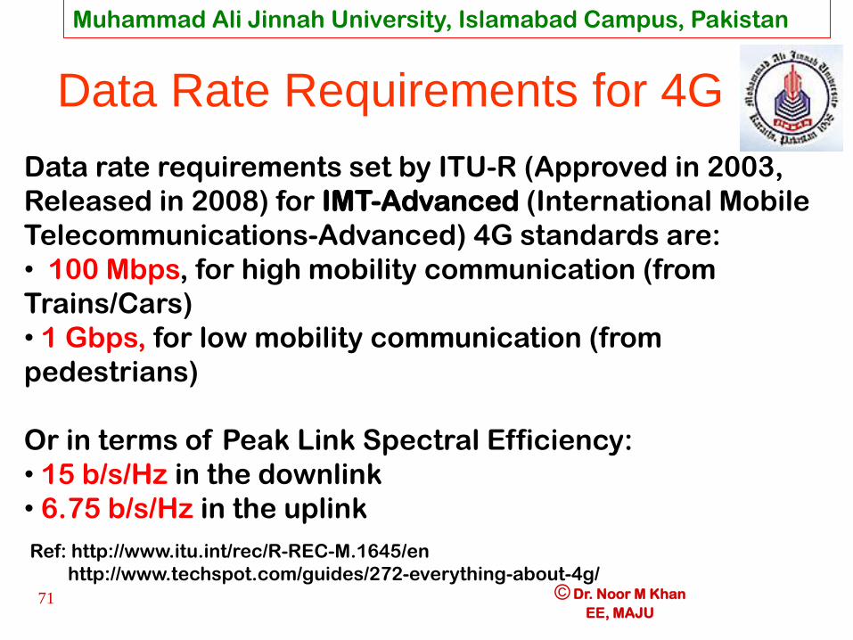
Data Rate Requirements for 4G
Data rate requirements set by ITU-R (Approved in 2003,
Released in 2008) for IMT-Advanced (International Mobile
Telecommunications-Advanced) 4G standards are:
• 100 Mbps, for high mobility communication (from
Trains/Cars)
• 1 Gbps, for low mobility communication (from
pedestrians)
Or in terms of Peak Link Spectral Efficiency:
• 15 b/s/Hz in the downlink
• 6.75 b/s/Hz in the uplink
Ref: http://www.itu.int/rec/R-REC-M.1645/en
http://www.techspot.com/guides/272-everything-about-4g/

Muhammad Ali Jinnah University, Islamabad Campus, Pakistan
© Dr. Noor M Khan
EE, MAJU Introduction to Wireless
Communications
EE/ECE6733 Cellular Mobile Communications
Week 1-2-3-4 ; Fall - 2013 72
Cellular System
PSTN MSC

Muhammad Ali Jinnah University, Islamabad Campus, Pakistan
© Dr. Noor M Khan
EE, MAJU Introduction to Wireless
Communications
EE/ECE6733 Cellular Mobile Communications
Week 1-2-3-4 ; Fall - 2013 73
Cellular Telephone System
Structure
• A cellular telephone system consists of:
– Mobile stations (MS)
• Handheld or vehicular
– Base stations (BS)
• Towers supporting several transceivers
– Mobile switching center (MSC) or mobile
telephone switching office (MTSO)
• Activity control of all BS, connects to PSTN
Muhammad Ali Jinnah University, Islamabad Campus, Pakistan
© Dr. Noor M Khan
EE, MAJU Introduction to Wireless
Communications
EE/ECE6733 Cellular Mobile Communications
Week 1-2-3-4 ; Fall - 2013 74
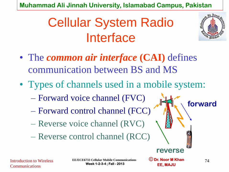
Cellular System Radio
Interface
• The common air interface (CAI) defines
communication between BS and MS
• Types of channels used in a mobile system:
– Forward voice channel (FVC)
– Forward control channel (FCC)
– Reverse voice channel (RVC)
– Reverse control channel (RCC)
reverse
forward

Muhammad Ali Jinnah University, Islamabad Campus, Pakistan
© Dr. Noor M Khan
EE, MAJU Introduction to Wireless
Communications
EE/ECE6733 Cellular Mobile Communications
Week 1-2-3-4 ; Fall - 2013 75
Cellular Telephone System
• Forward voice channel (FVC)
– BS to MS voice transmission
• Reverse voice channel (RVC)
– MS to BS voice transmission
• Forward control channel (FCC) and Reverse control channel (RCC)
– Setting up mobile call and moving it to voice channel
Muhammad Ali Jinnah University, Islamabad Campus, Pakistan
© Dr. Noor M Khan
EE, MAJU Introduction to Wireless
Communications
EE/ECE6733 Cellular Mobile Communications
Week 1-2-3-4 ; Fall - 2013 76
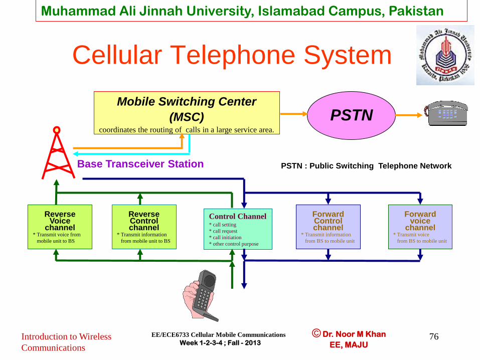
Cellular Telephone System
Mobile Switching Center
(MSC) coordinates the routing of calls in a large service area.
PSTN
PSTN : Public Switching Telephone Network Base Transceiver Station
Forward Control channel
* Transmit information
from BS to mobile unit
Forward
voice channel
* Transmit voice
from BS to mobile unit
Reverse Control channel
* Transmit information
from mobile unit to BS
Reverse
Voice channel
* Transmit voice from
mobile unit to BS
Control Channel * call setting
* call request
* call initiation
* other control purpose

Muhammad Ali Jinnah University, Islamabad Campus, Pakistan
© Dr. Noor M Khan
EE, MAJU Introduction to Wireless
Communications
EE/ECE6733 Cellular Mobile Communications
Week 1-2-3-4 ; Fall - 2013 77
Cellular Telephone Call
• Mobile station (phone) turned on
– it scans for the group of forward control channels(FCC) to find the one with the strongest signal
– Monitors that control channel until the signal drops below usable level
– Again scans for the strongest control channel
• The control channels are defined and standardized over the entire area

Muhammad Ali Jinnah University, Islamabad Campus, Pakistan
© Dr. Noor M Khan
EE, MAJU Introduction to Wireless
Communications
EE/ECE6733 Cellular Mobile Communications
Week 1-2-3-4 ; Fall - 2013 78
Call to a Mobile Phone
RVC
FVC
RCC
FCC
Mobile
Station
RVC
FVC
RCC
FCC
Base
Station
Receives call from PSTN Sends the MIN to all base stations
MSC
Receives page and matches the MIN with its own
Transmits page (MIN) for specified user
Acknowledges receipt of MIN and sends ESN and Station Class Mark
Receives MIN, ESN, Station Class Mark and passes to MSC
Requests BS to move mobile to unused voice channel pair
Verifies that the mobile has a valid MIN, ESN pair
Receives data message to move to specified voice channel
Connects the mobile with the calling party on the PSTN
Begin voice reception
Begin voice transmission
Begin voice reception
Begin voice transmission
Transmits data message for mobile to move to voice channel
Muhammad Ali Jinnah University, Islamabad Campus, Pakistan
© Dr. Noor M Khan
EE, MAJU Introduction to Wireless
Communications
EE/ECE6733 Cellular Mobile Communications
Week 1-2-3-4 ; Fall - 2013 79
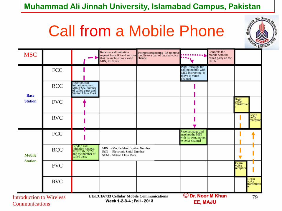
Call from a Mobile Phone
RVC
FVC
RCC
Sends a call initiation request, MIN,ESN, SCM and the number of called party
FCC
Mobile
Station
RVC
FVC
RCC
FCC
Base
Station
MSC Instructs originating BS to move mobile to a pair of unused voice channel
Receives call initiation request from BS and verifies that the mobile has a valid MIN, ESN pair
Connects the mobile with the called party on the PSTN
Page message for calling mobile with MIN instructing to move to voice channel
Receives page and matches the MIN with its own, moves to voice channel
Begin voice reception
Begin voice transmission
Begin voice reception
Begin voice transmission
Receives call initiation request, MIN,ESN, number of called party and Station Class Mark.
MIN - Mobile Identification Number ESN - Electronic Serial Number SCM - Station Class Mark

Muhammad Ali Jinnah University, Islamabad Campus, Pakistan
© Dr. Noor M Khan
EE, MAJU Introduction to Wireless
Communications
EE/ECE6733 Cellular Mobile Communications
Week 1-2-3-4 ; Fall - 2013 80
Roaming(1)
• Roaming allows subscribers to operate in mobile phone service areas other then the service area where the service is subscribed
• When a mobile enters area outside the home service area it is registered as roamer in the new service area
• Since FCC are everywhere the same, roamer is receiving information from FCC
Muhammad Ali Jinnah University, Islamabad Campus, Pakistan
© Dr. Noor M Khan
EE, MAJU Introduction to Wireless
Communications
EE/ECE6733 Cellular Mobile Communications
Week 1-2-3-4 ; Fall - 2013 81
Roaming(2)
• Every several minutes MSC issues command over each FCC to all mobiles previously unregistered to report their MIN and ESN over the RCC
• Unregistered mobiles periodically report back subscriber information upon receiving the registration request
• The MSC uses MIN/ESN data to request billing status from the home location register (HLR)
• If the mobile has roaming authorization at home, MSC registers the subscriber in a visiting location register (VLR) as a valid roamer
• Once registered roaming mobiles are allowed to receive and place calls from the new service area
• Billing is routed automatically to the subscribers home service provider (HLR)