Embed Size (px)
Citation preview
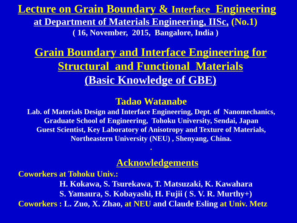
Grain Boundary and Interface Engineering for
Structural and Functional Materials
(Basic Knowledge of GBE)
Tadao WatanabeLab. of Materials Design and Interface Engineering, Dept. of Nanomechanics,
Graduate School of Engineering, Tohoku University, Sendai, Japan
Guest Scientist, Key Laboratory of Anisotropy and Texture of Materials,
Northeastern University (NEU) , Shenyang, China.
.
Lecture on Grain Boundary & Interface Engineering at Department of Materials Engineering, IISc, (No.1)
( 16, November, 2015, Bangalore, India )
AcknowledgementsCoworkers at Tohoku Univ.:
H. Kokawa, S. Tsurekawa, T. Matsuzaki, K. Kawahara
S. Yamaura, S. Kobayashi, H. Fujii ( S. V. R. Murthy+)
Coworkers : L. Zuo, X. Zhao, at NEU and Claude Esling at Univ. Metz

Outline
1. Historical Background of Grain Boundary Engineering
Basic Studies of
(1). “Structure-dependent Grain Boundary (GB) Properties” in Bicrystals
for Design and Control of GB-Related Bulk Properties in Polycrystals:
(2). “New Microstructural Parameters” to characterize “GB Microstructure”
and to bridge a Gap between Individual Grain Boundaries and Bulk
Properties in a Polycrystal:
“GB Character Distribution (GBCD)”, “GB Connectivity” & etc.
2. Control of Texture and Grain Boundary Microstructures How to relate “Texture” to “GB Microstructure” in Polycrystals.How to manipulate Microscale Texture and GB Microstructure.
3. Grain Boundary Engineering for GB-controlled Bulk Propertiesin “Structural” and “Functional” Materials
4. Future Persupective of Interface Engineering for Biological
Materials.

A Polycrystal System of Grains and Grain Boundaries
( Mo ingot solidified from the melt )
First Book on Grain Boundaries in Metals
Polycrysdtalline

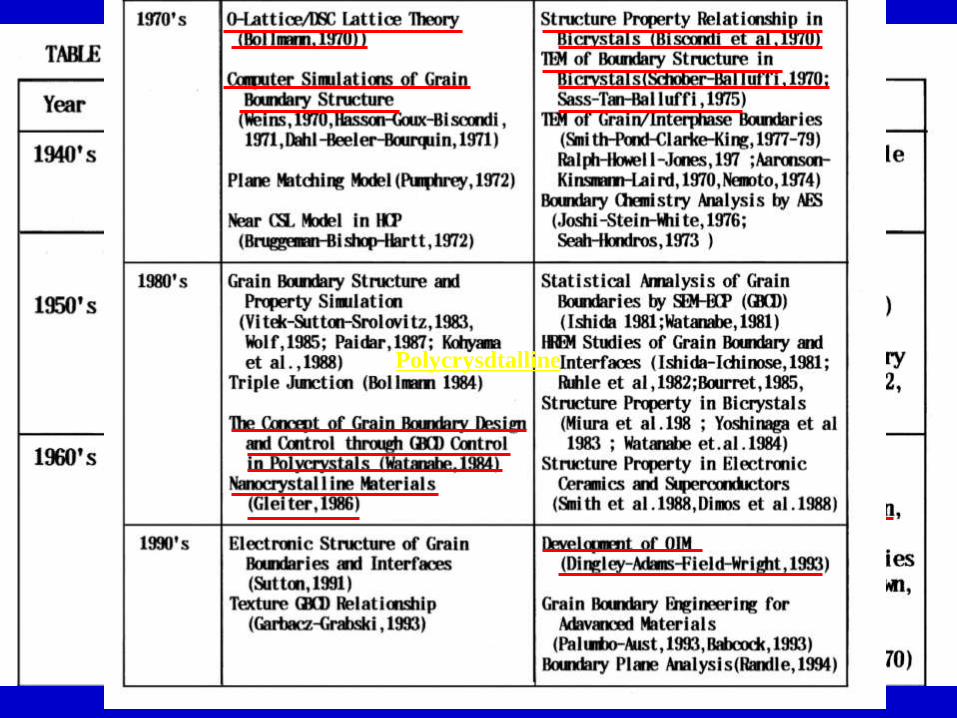
A Brief History of Studies of Grain Boundary Structure
and Properties leading to Grain Boundary Engineering
1900s-1940s
Amorphous Cement Theory ( Rosenhain-Ewen: 1912 )
Transition-Lattice Theory ( Hargreaves-Hill: 1929 )
GB Structure : CSL Model (Kronberg-Wilson: 1949)
Geometrical and Topological Approach to GB microstructure ( C. S. Smith: 1948 )
1950s-1960s
Dislocation Theory of Low-angle GBs ( Read-Schokley: 1952, Amelincks: 1957 )
Boundary Structure and Properties in Bicrystals ( Chalmers-Aust, R. W. Cahn: 1953 )
Thermodynamics of GBs ( J. W. Cahn,1956 ), First Book on GBs ( D. McLean: 1957 )
Geometrical and Mathematical Approach to CSL ( Brandon, Ranganathan :1966 )
FIM, TEM Observations ( Ryan-Suiter, Ralph-Jones, Gleiter )
1970s- 1980s
HREM of GB (Schober-Balluffi, Sass, Pond-Smith, Ishida-Ichinose,
Thibault, Bourret-Bacman, Rühle )
Bicrystal Work in Metals ( France, Russia, Japan ), O-Lattice Theory ( Bollmann: 1968)
Computer Calculations ( Biscondi, Vitel-Sutton, Wolf, Kohyama)
Microscale Texture ( Gottstein-Lȕcke: 1978, Bunge-Esling,: 1986 )
Nanocrystalline Materials ( Gleiter : 1986 ),
Grain Boundary Engineering ( Watanabe: 1983-1984, Aust –Palumbo: 1989 )
1990s-2000s
SEM-EBSD/OIM ( Adams, Wright, Kunze: 1994),
Bicrystals ( Metals: Gottstein-Shvindlerman-Molodov,
Ceramics :Sakuma-Ikuhara- Yamomoto-Shibata )
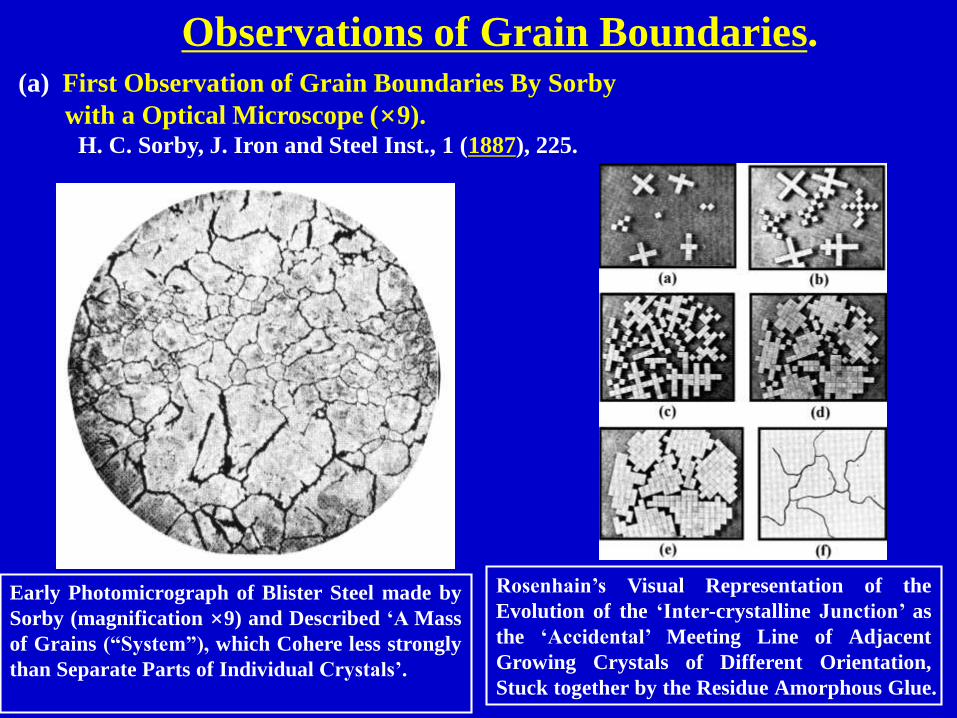
Observations of Grain Boundaries.(a) First Observation of Grain Boundaries By Sorby
with a Optical Microscope (×9).H. C. Sorby, J. Iron and Steel Inst., 1 (1887), 225.
Early Photomicrograph of Blister Steel made by
Sorby (magnification ×9) and Described ‘A Mass
of Grains (“System”), which Cohere less strongly
than Separate Parts of Individual Crystals’.
Rosenhain’s Visual Representation of the
Evolution of the ‘Inter-crystalline Junction’ as
the ‘Accidental’ Meeting Line of Adjacent
Growing Crystals of Different Orientation,
Stuck together by the Residue Amorphous Glue.

It is proposed that a thin layer of amorphous
metal may be formed and may persist in the
intercrystalline boundaries, even in the
absence of strain. ( W. Rosenhain, D. Ewen:
J. Inst. Metals, 8 (1912), 149~185.)
36.5°<001>/Σ5
Formation of Transition Zone
Patterns. To illustrate the conception
and not to give the actual positions of
the atoms ( F. Hargreaves, R. J.
Hills: J. Inst. Metal, 41 (1929),
257~288 )
Early Theories of Grain Boundary Structure in 1900s-1920s
Transition-Lattice Theory
Amorphous Cement Theory

Geometrical and Topological Approach to Microstructure
in Polycrystal (1940s-1950s)
Cyril Stanley Smith
“Soap Bubble Model” of Grain Growth
and Microstructural Evolution.
( 1903 ~ 1992 )
Background of Grain Boundary & Interface Engineering
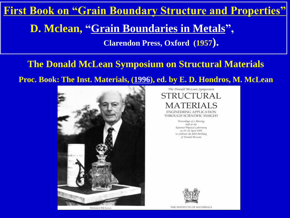
First Book on “Grain Boundary Structure and Properties”
D. Mclean, “Grain Boundaries in Metals”,
Clarendon Press, Oxford (1957).
The Donald McLean Symposium on Structural Materials
Proc. Book: The Inst. Materials, (1996), ed. by E. D. Hondros, M. McLean

Importance of Grain Boundary Structure
K.T. Aust and B. Chalmers : “Energies and Structure of Grain Boundaries”,
Metal Interfaces, ASM, (1952), 153-178.
K. T. Aust B. Chalmers

Effects of Grain Boundary Structure on Grain Boundary
Migration ( Pb-Sn Alloy bicrystals )
K. T. Aust and J. W. Rutter, Trans. Met. Soc. AIME., 215 (1959), 119-127.

Structure-dependent Grain Boundary Migration in Metals of Different Purity.
G. Gottstein, L. S.Shvindlerman: Scripta Met., 27 (1992), 1515-1520.

Pioneers in Grain Boundary Research Field
Mrs. Brandon, Prof. S. Ranganathan (IISc.), Prof. D. Brandon
(Technion)
( on the occasion of The 11th Israel Mater. Eng. Conf. in Haifa, on 23 Dec., 2003 )

Coincidence-Site Lattice (with S=9) based on [210].
( S. Ranganathan: Acta Cryst., 21 (1966), 197.)
Ranganathan’s equation
( D. Brandon, Acta Met., 14 (1966),1479)
Δ
15Δθ=
222
22
lkh=
y =x
R
RBrandon’s
Criterion
Mathematical Prediction of Coincidence-Site-Lattice Boundaries
S = 11 Boundary.


Our Pioneers who have led us for many years in
research field of Grain Boundary and Interfaces
T. S. Ke R. W. Cahn J. W. Christian H. I. AaronsonD. McLean
R. C. Gifkins P. Haasen D. A. Smith Y. Ishida R. W. Balluffi

Effects of Grain Boundaries on “Bulk Properties”Two-fold Effects: “Beneficial” or “Detrimental”
Early Work on “Grain Size Effects” on Deformation and Fracture.
“Hall-Petch Relationship”
Hall-Pethch Plots for Lower Yield Stress, Flow
Stress and Fracture Stress for Mild Steel.
N. J. Petch
2
1-
0 kdσ=σ
E.O.Hall; Proc. Phys. Soc., Lond. B, 64 (1951), 747.
N. J. Petch, ;J. Iron St. Inst., 174 (1953), 25.
Flow Stress, s
or
Fracture Stress,
d : Grain Size

Grain Size Dependence of Fracture Stress
in Various SteelsA.R. Rosenfield & G.T. Hahn: Trans. ASM., 59 (1966), 962

Roles of Grain Boundaries in Plastic Deformation Grain Boundaries as Preferential Sites for
Nb: A. Berghezan & A. Fourdeux:
J. Less Common Metals, 28(1972), 357
Stainless Steel; M. J. Whelan,& P. B. Hirsch;
Phil. Mag., 2(1957), 1121
“Dislocation Nucleation” “Dislocation Pile-up”

Type of grain boundary ;
(a) G.B. No. 1: Random Boundary,
(b) G.B. No.2: slightly off-S13b Coincidence
Boundary:
H. Kokawa, T. Watanabe and S. Karashima;
J. Mater. Sci., 18 (1983), 1183-1194.
R
S13
Interactions of Lattice Dislocations with Grain BoundariesAluminium Polycrystal Specimen Crept up to 1.3% Elongation
at Tensile Stress of 5 MPa and 600K.

Heterogeneity of Grain Boundary Phenomena
in Polycrystalline Materials
Corrosion MigrationGrain Boundary Fracture
“The extent of occurrence” of grain boundary phenomenon are quite different from
boundary to boundary, demonstrating “the difference in effectiveness of GB ” as
preferential sites for metallurgical phenomena controlling bulk properties.
This suggests Possible Effects of “GB Type and Structure” on “GB Properties”.

Square Networks of Screw GBD’s Observed
in Vicinities of CSL Misorientations : (a)
near q = 0°, S = 1; (b) near q = 36.9°, S = 5;
(c) near q = 22.6°, S = 13; (d) near q = 28.1°,S = 17. Note that the GBD Contrast
Decreases as S Increases. ( R.W. Balluffi, Y.
Komen and T. Schober, Suf. Sci., 31 (1972),
68-103.)
Absorbed Lattice Dislocations in a Grain
Boundary in an Fe-0.75%Mn-0.01%N
Alloy, Creep Tested at 773K to 0.94%
Strain. ( Y. Ishida and M. Henderson
Brown, Acta Metall., 15 (1967), 857-860. )
TEM Observations of GB Intrinsic and Extrinsic Dislocations

DSC-Lattices formed by interpenetrating (001)
planes of simple Cubic Lattices rotated with
respect to one another by Angle q around [001].
Top: q = 36.9 (S = 5). Bottom: q = 28.1 (S = 17).
The Burgers vectors of the DSC-intrinsic
dislocations are shown at the center of each
diagram.
Observed Primary Relaxation Spacing, d, and
Secondary Relaxation Spacing, ds, in [001] Twist
Boundaries in Gold as a Function of Twist Angle q.
Displacement Shift Complete
( DSC ) Lattice Model
R. W. Balluffi: “Grain Boundary Structure
and Segregation”, Interfacial Segregation,
ASM., (1979), 193-237.

(a) (b) (c) (d)
HREM Image of the (443) Symmetric
Tilt GB (tilt angle y= 55, S = 41).
High Resolution Micrographs Various Tilt Grain Boundary Structures Exhibiting
Dislocation Strain Field and Lattice Fringe Contrasts in Gold.( W. Krakow and D. A. Smith, Trans. JIM Suppl. 27 (1986), 277-284)
(a) 18°[001] / (610) (b) 28°[001] / (410)
(c) 10°[110] / (881) (d) 28°[110] / (331)
High Resolution TEM Observations of Grain Boundaries in Gold

Variations in Grain Boundary Energy for Symmetric Tilt Grain Boundaries
in Al Bicrystal. ( G. Hasson, J. –Y. Boos, I. Herbeuval, M. Biscondi and C.
Goux : Surface Science, 31 (1972), 115-137. )
(a) [100] tilt (b) [110] tilt
Misorientation-dependent Grain Boundary Energy
in [100] and [110 tilt] Al Bicrystals

Basic Study of Grain Boundary Properties in Bicrystals
Examplse: Structure-dependent Grain Boundary Energy
A. Otsuki: Al bicrystals: Trans. JIM., 27 (1986), 789, J. de. Phys., 49 (1988), C5-563,
Si bicrystals: Acta Mater., 49 (2001), 1737-1745.
Microscale Texture ( Bunge-Gottstein,

HREM Images for Grain Boundary Atomic Structuresdepending on Misorientation in ZrO2 Bicrystals
Y. Ikuhara, N. Shibata, T. Watanabe, F. Oba, T. Yamamoto and T. Sakuma,
Ann. Chim. Sci. Mat.: 27 (2002) Suppl 1, S21-30.

Misorientation Dependence of Grain Boundary Energy<110> Symmetric Tilt Boundaries in ZrO2
Y. Ikuhara, N. Shibata, T. Watanabe, F. Oba, T. Yamamoto and T. Sakuma;
Proc. Japan-France Joint Symp., Ann Chim Sci. Mat., 27(2002), Suppl 1:
S21-30 , or H. Yoshida et al; Acta Mater., 52 (2004), 2349.

Structure-Dependent Grain Boundary Hardness
in <100> Tilt Niobium Bicrystals.
Y. T. Chou, B. C. Cai, A. D. Romig, Jr., L. S. Lin; Phil. Mag. A, 47 (1983), 363-368.

Structure-dependent Grain Boundary Sliding and Structural
Transformation in <1010>Symmetric Tilt Zinc Bicrystals.
T. Watanabe, S. Kimura, S. Karashima: Phil. Mag., 49 (1984), 845-864.
“The Effect of a grain boundary structural transformation on Sliding
in <1010> tilt zinc bicrystals”.
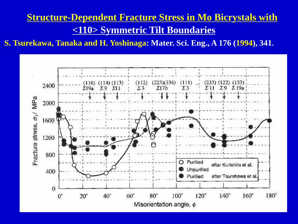
S. Tsurekawa, Tanaka and H. Yoshinaga: Mater. Sci. Eng., A 176 (1994), 341.
Structure-Dependent Fracture Stress in Mo Bicrystals with
<110> Symmetric Tilt Boundaries

Structure-Dependent Fracture Stress and Strain
in <1010> Tilt and <1010> Twist Zinc Bicrystals.
( T. Watanabe, S. Shima and S. Karashima:
Embrittlement by liquid and solid metals, Met. Soc.
AIME, (1984), 161-172)
Structure-Dependent Fracture Stress and Strain
in Cu-Bi <110> Tilt Bicrystals.
( H. Miura, T. Yoshida, T. Sakai, M. Kato and
T. Mori, J. Jpn. Inst. Metals, 57 (1993), 479-485)
S3S11
S3S11
Structure-Dependent Fracture Stress and Strain
Liquid Hg-induced Fracture in Zn Bismuth-induced Fracture in Cu

Fracture Stress Data for Different Types of Grain Boundaries
L. C. Lim and T. Watanabe; Acta Metall. Mater., 38 (1990), No.12, 2507-2516.

Schematic Diagram of Two Types of Structure-dependent
Grain Boundary Properties in BicrystalsT. Watanabe: “Grain boundary engineering: historical perspective and future prospects”,
J. Mater. Sci., 46 (2011), 4095-4115

SEM Micrographs Showing (a) the Surface of
Tricrystal Specimen Deformed at 1073K under 6 MPa
for 200h and (b) the Enlarged View of Triple Junction.
( S. Miura, T. Okada, S. Onaka and S. Hashimoto:
Colloq. de Phys., C1, 51 (1990), C1-587-592.)
Stress-strain Curves of <100> Bicrystals
having 4 °, 14° and 37° Boundaries and
Component Single Crystals.
( S. Miura and Y. Saeki: Acta Met.. 26
(1978), 93-101.)
Basic Study of Deformation in Bicrystals and Tricrystal
( S. Miura, S. Hashimoto, et al. )

From “GB Science” to “GB Engineering” ( Started in 1980s and being attempted increasingly up to now )
Progressing Steps to “Grain Boundary and Interface Engineering”.
1. Recognition of Basic knowledge of “Structure-dependent Properties”
“Effectiveness “ of grain boundaries and interfaces.
2. Quantitative and Statistical analysis of “Grain Boundary Microstructure
(GBM)” in Polycrystalline Materials.
3. Need of “New Microstructural Parameters” to describe GBM.
4. Importance of “Grain Boundary Character Distribution (GBCD)” and
“Grain Boundary Connectivity.” –OIM Analysis.
5. “Design and Control of Grain Boundary Microstructures” based on the
Understanding of “Percolation Processes of Grain Boundary-related
Phenomena” in Polycrystalline Material System.
6. Demand for Development of “A New Processing Technique for GBE”.
7. “The Importance of Grain Boundary Engineering (GBE)” increases
with increasing “Density of Grain boundaries” and their Directionality” :
“Nanocrystalline and Textured Materials”

Grain Boundary and Interface Engineering for
Structural and Functional Materials
Tadao Watanabe
Lab. of Materials Design and Interface Engineering, Dept. of Nanomechanics,
Graduate School of Engineering, Tohoku University, Sendai, Japan
Guest Scientist, Key Laboratory of Anisotropy and Texture of Materials,
Northeastern University (NEU) , Shenyang, China.
.
Lecture on Grain Boundary & Interface Engineering at Department of Materials Engineering, IISc, (No.2)
( 18, November, 2015, Bangalore, India )
AcknowledgementsCoworkers at Tohoku Univ.:
H. Kokawa, S. Tsurekawa, T. Matsuzaki, K. Kawahara
S. Yamaura, S. Kobayashi, H. Fujii ( S. V. R. Murthy+)
Coworkers : L. Zuo, X. Zhao, at NEU and Claude Esling at Univ. Metz

The Concept of Grain Boundary Design and Control:
“Grain Boundary Engineering”
The Potential of Grain Boundary Engineering(1) Enhancement of “Beneficial Effects”
(2) Control of “Detrimental Effects”
(3) Generation of “A New Function” and “Desirable Bulk Property”
by Controlling “Grain Boundary Microstructure”
(4) Properties are due to the Interaction of GB & Interfaces with Defects
Characterization of Grain Boundary Microstructure(1) Grain Boundary Character Distribution (GBCD)
(2) Grain Boundary Connectivity, (3) Triple Junction Character Distribution,
(4) GBCD vs Grain Size, (5) GBCD vs Texture (Grain Orientation Distribution)
(6) Grain Boundary Inclination Distribution ( Directional GBM )
(7) Grain Boundary Chemistry Distribution
T. Watanabe : “An Approach to Grain Boundary Design for Strong and
Ductile Polycrystals” Res Mechanica, 11 (1984), 47-84.
T. Watanabe: “Grain Boundary Engineering: Historical Perspective and
Future Prospects” , J. Mater. Sci., 46 (2011), No.12, 4095-4115.
T. Watanabe: in “Microstructural Design of Advanced Eng. Mater.” Wiley (2013).

Grain Boundary & Interface Engineering for Advanced Materials

A Polycrystal System of Grains and Grain Boundaries
( Mo ingot solidified from the melt )

Recent Technique for Characterization of Grain
Boundary Microstructures in Polycrystals
Orientation Imaging Microscopy (OIM)
FE-SEM/EBSD/OIM
( Hitachi S-4200 )
B. Adams, S. I. Wright and K. Kunze:
Metal. Trans., 24A (1993), 819-831.

Characterization and Classification of Grain Boundaries
1. Low-angle Boundaries based on Dislocation Model.---Pure Tilt-, Pure Twist-, Mixed-type Boundary.
2. High-angle Boundaries:(a) High-angle Random/General Boundary
(b) High-angle Special Boundaries:
----Symmetrical and Asymmetrical Boundaries.
--- Coincidence Site Lattice (CSL) Boundaries.
--- Plane-matching Boundaries.
--- Close-packed Plane Aligned Boundaries.
Current Theories of Grain Boundary Structure.“The Structure-Unit Models” of Periodic/Ordered GB Structures.
A. Sutton, V. Vitek: Phi. Trans. Roy. Soc. Lond., A309 (1983), 1-36.
A. Sutton, R. W. Balluffi: Interfaces in Crystalline Materials,
Oxford Science Pubs., (1995), Chap.4, “Atomic Structure of Interfaces”

Molybdenum Polycrystal ( Produced by Thermomechanical Processing from Single
Crystal with {111} Initial Orientation 78% Deformed under Compression and then
Annealed at 1873K for 7.2ks ).
Characterization of Grain Boundary Microstructure
in a Polycrystal by SEM-EBSP/OIM ( Mo )T. Watanabe, “Grain Boundary Architecture for High Performance Materials”,
D. A. Smith Symp. on Grain Boundaries and Interfaces in Materials, TMS (1998), pp.19~28.
(a) Optical Micrograph. (b) GBCD and Boundary Connectivity.
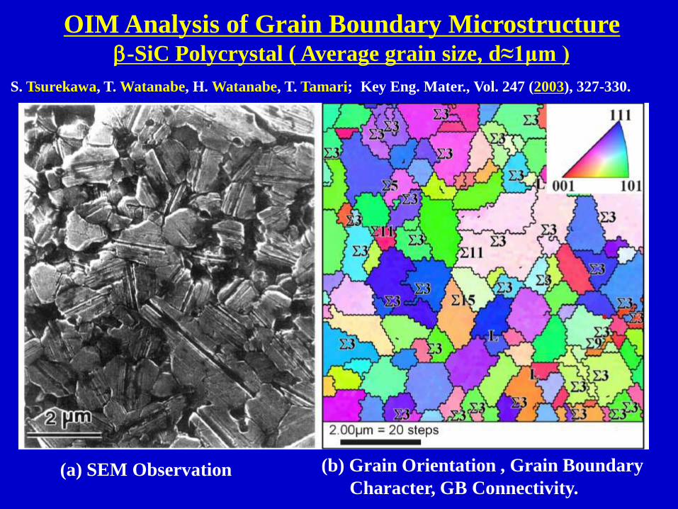
OIM Analysis of Grain Boundary Microstructure b-SiC Polycrystal ( Average grain size, d≈1μm )
(a) SEM Observation (b) Grain Orientation , Grain Boundary
Character, GB Connectivity.
S. Tsurekawa, T. Watanabe, H. Watanabe, T. Tamari; Key Eng. Mater., Vol. 247 (2003), 327-330.

ECP Analysis and Characterization of Grain
Boundaries in a Tensile Fracture Test
Specimen. Beta-Brass Polycrystal with Grain
Size from 1.4 to 4.0 mm. The Dimensions of
the Gauge Part of the Specimen are 5 mm
Wide, 20 mm Long and 1 or 2mm Thick.
In-situ Observation of Crack Propagation in
Liquid-gallium-induced Fracture of Beta-Brass
Polycrystal. Note the Change in Fracture Mode
between Intergranular and Transgranular
Fracture, depending on the Type of Grain
Boundary in front of the Propagating Crack.
T. Watanabe; Res Mechanica, 11 (1984), No.1, 47-84.
In-situ Observations of Fracture Processes in Polycrystals -How to bridge between Property of Individual Boundaries and Bulk Property-

Grain Boundary Structure-dependent Fracture
Processes in a Polycrystal
Path A: Combined Process of Intergranular and Transgranular Fracture.
Path B: Typical Intergranular Fracture.
T. Watanabe: Res Mechanica,11 (1984), 47-84.

The First Systematic Study of GBCD in Metallic Polycrystals.
Al polycrystals produced by thermomechanical processing
from single crystals with different initial orientations.
( SEM-ECP Analysis of GB Microstructure )T. Watanabe, No. Yoshikawa, S. Karashima: Proc. ICOTOM-6, (1981), 609-618
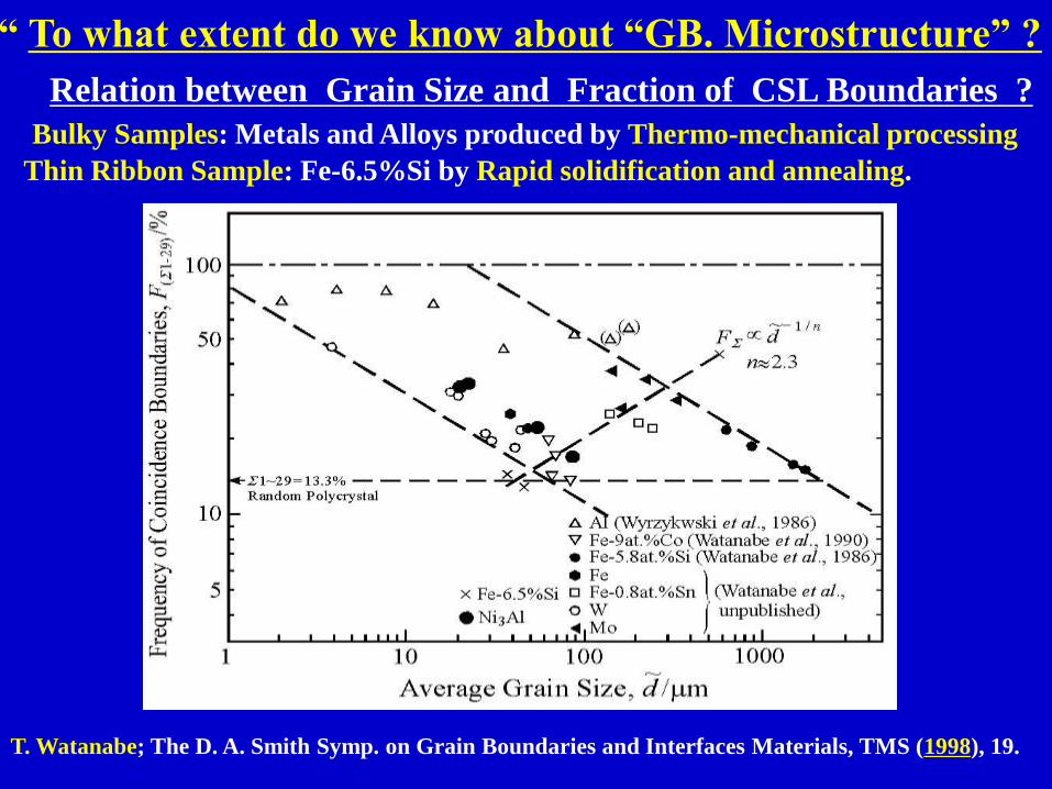
Relation between Grain Size and Fraction of CSL Boundaries ?
Bulky Samples: Metals and Alloys produced by Thermo-mechanical processing
Thin Ribbon Sample: Fe-6.5%Si by Rapid solidification and annealing.
T. Watanabe; The D. A. Smith Symp. on Grain Boundaries and Interfaces Materials, TMS (1998), 19.
“ To what extent do we know about “GB. Microstructure” ?

Grain Orientation Distributions for Fe-6.5 wt. % Si
Ribbons Annealed Differently. Specimen A: 1173K,
3.6ks, Specimen B: 1363K, 600s, Specimen C: 1363K,
3.6 ks, Specimen D: 1473K, 3.6ks.
The Frequency of CSL Boundaries as
a Function of S for Rapidly Solidified
and Annealed Fe-6.5 wt.% Si Ribbons.
Grain Boundary Character Distribution (GBCD) vs Texture
T. Watanabe et al.: Acta Met., 37(1989), 941, Phil. Mag. Letters, 59 (1989), 47,
Textures and Microstructures, 20 (1993), 195-216.)
Spec. A
Spec. B
Spec. C
Spec. D
Spec. C
Spec. D

The Inverse Cubic Root S Dependence of
Coincidence Boundaries in Rapidly Solidified
and Annealed Fe-6.5 mass % Si Ribbons.
The Inverse Cubic Root S Dependence of the
Frequency of Low S Coincidence Boundaries in
Materials with BCC and FCC Structures.
The Inverse Cubic Root S Plot of Coincidence Boundaries T. Watanabe, H. Fujii, H. Oikawa, K. I. Arai: Acta Metal, Vol.37 (1989), 941~952

Theoretical Work on Grain Boundary Character Distribution
in Differently Textured Polycrystals in Cubic Crystal.
A. Garbacz, M. W, Grabski: Acta Met Mater., 41 (1993), 469-473

Misorientation Angles with Low Interfacial Energies Occur at Angles Known to
Correspond to {110} CSL Symmetric Tilt Boundaries with small Sigma Values.
( A. Zimbouski, C. S. Kim, G. Rohrer, A. D. Rollett and T. Watanabe, (2003),
cited in T. Watanabe: J. Mater. Sci., 46 (2011), No.12, 4095-4115 )
Grain Boundary Energy vs Misorientation Angle
in {110} Textured Fe-6.5%Si Ribbon

Annealing Textures in 304 L Stainless Steel produced by
Thermomechanical Processing from Single Crystals with
Different Initial Orientations
S. Tsurekawa, S. Nakamichi, T. Watanabe: Acta Mater., 54 (2006), 3617-3626

The Frequency of Low-S CSL Boundaries vs Grain Size 304L Austenitic Stainless Steel ( with Low-Stacking Fault Energy )
produced by Thermomechanical Processing from Single Crystals
S. Tsurekawa, S. Nakamichi, T. Watanabe: Acta Mater., 54 (2006), 3617-3626
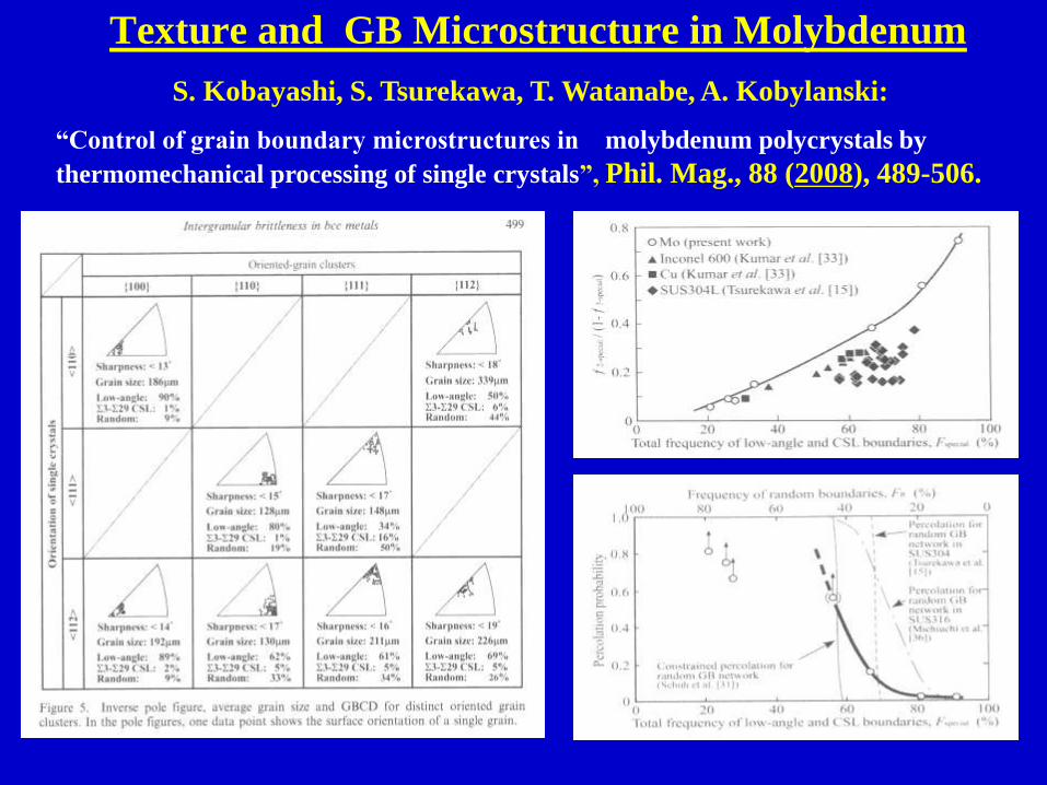
Texture and GB Microstructure in Molybdenum
S. Kobayashi, S. Tsurekawa, T. Watanabe, A. Kobylanski:
“Control of grain boundary microstructures in molybdenum polycrystals by
thermomechanical processing of single crystals”, Phil. Mag., 88 (2008), 489-506.

S. Kobayashi, S. Tsurekawa, T. Watanabe, A. Kobylanski:
“Control of grain boundary microstructures in molybdenum polycrystals by
thermomechanical processing of single crystals”, Phil. Mag., 88 (2008), 489-506.
Texture and GB Microstructure in Molybdenum
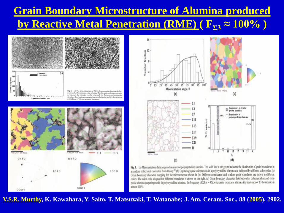
Grain Boundary Microstructure of Alumina produced
by Reactive Metal Penetration (RME) ( FΣ3 ≈ 100% )
V.S.R. Murthy, K. Kawahara, Y. Saito, T. Matsuzaki, T. Watanabe; J. Am. Ceram. Soc., 88 (2005), 2902.

Our Long Pending Preoblem in Materials Development
for Structural Materials.
• Enhanced strength tends to bring about Poor
Ductility and Severe Brittleness in almost all
kinds of Polycrystalline Materials:
• Increasing grain size generally enhances GB
Brittleness in metallic materials.
• Severe GB Brittleness can also occur in Nano-
crystalline materials.
• The main source of Brittleness is GB fracture.
Our Challenge: How to solve this dilemma ?

Long Pending Problem of Structural Materials:
How to Solve the Dilemma between Enhanced Strength
and Brittleness in Structural Engineering Materials
Our Challenge :
Toughening by Grain Boundary Engineering (GBE).
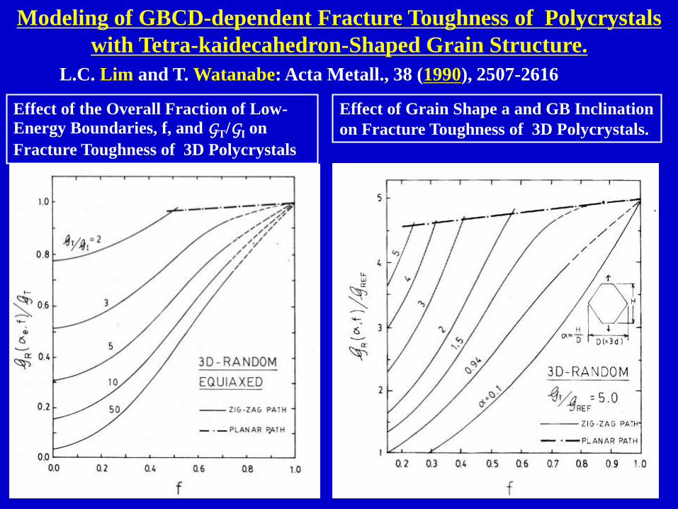
Effect of the Overall Fraction of Low-
Energy Boundaries, f, and GT/GI on
Fracture Toughness of 3D Polycrystals
Effect of Grain Shape a and GB Inclination
on Fracture Toughness of 3D Polycrystals.
L.C. Lim and T. Watanabe: Acta Metall., 38 (1990), 2507-2616
Modeling of GBCD-dependent Fracture Toughness of Polycrystals
with Tetra-kaidecahedron-Shaped Grain Structure.

Grain Boundary Engineering for Control of Intrinsic
Brittleness of Ni3Al Polycrystals without Boron
T. Watanabe, T. Hirano, T. Ochiai, H. Oikawa: Mater. Sic. Forum,157-162 (1994), 1103

Fracture Behaviour in Molybdnum Polycrystals with Two
Different Types of Grain Boundary Microstructures
Before Fracture Test Type I Type IType II Type II
After Fracture Test
T. Watanbe, S. Tsurekawa: Acta Mater., 47 (1999), 4171-4185

Fracture Behaviour in Molybdnum Polycrystals with Two
Different Types of Grain Boundary Microstructures
T. Watanabe, S. Tsurekawa: Acta Mater., 47 (1999), 4171-4185.
“The control of britleness and development of desirable mechanical
properties in Polycrystalline systems by grain boundary engineering”

Grain Size Dependence of Fracture Stress
controlled by GBCD in Polycrystalline Mo
S. Tsurekawa, T. Watanabe; MRS. Proc. on Interfacial Engineering
for Optimized PropertiesⅡ, 586 (2000), 237~242
Important Finding on The Hall-Petch: The slope changes depending of GBCD.

Grain Boundary Engineering for Improvement in Creep
Strength of Zn Bicrystals and Ni-base Alloy Polycrystal.
Creep Curves for <1010> Twist Zinc
Bicrystals with Different Boundaries
under Constant Resolved Shear Stress.
Effect of the Frequency of Low S(CSL)
Boundaries on Creep Deformation in
Ni-16Cr-9Fe Alloy at 360℃, s= 300MPa.
S9
S9
T. Thaveprungsriporn and G. S. Was;
Scripta Mater.,35 (1996),1, B. Alexandreanu
& G. S. Was: Scripta Mater. 54 (2006),1047.
T. Watanabe, M. Yamada and S. Karashima;
Phil. Mag., A63 (1993), 1013.

Change in Grain Boundary Microstructure during
Super-plastic Deformation in Al-Li Alloy.
Note: Evolution of an optimum grain boundary microstructure, particularly
the fraction of random boundaries during super-plastic deformation.
S. Kobayashi, T. Yoshimura, S. Tsurekawa and T. Watanabe: Mater. Trans. JIM, 44
(2003), 1469-1479.

Demonstration of Improvement in Super-
Plasticity by a Strain Rate Change Test at
723K.
Schematic Illustration for Evolution of a
new Grain Boundary Microstructure for
Improvement in Superplasticity.
Evolution of Optimal Grain Boundary Microstructure
for Enhancement of Super-plasticity in Al-Li Alloy.
S. Kobayashi, T. Yoshimura, S.Tsurekawa and T.Watanabe, Mater. Trans. JIM, 44
(2003), 1469-1479.

Grain Boundary Engineering for Control of Intergranular
Corrosion in Alloy 600 ( 75Ni-16Cr-9Fe Alloy )
1. G. Palumbo, E. M. Lehockey and P. Lin: “Applications for Grain Boundary Engineered
Materials”, J. Metals, 50 (1998), No.2, 40-43.
FS = 37% (S1~S29) FS = 70% (S1~S29)(b) GBE Processed Materials(a) Conventional Material
P. Lin, G. Palumbo, U. Erb, K. T. Aust: Scripta Met. Mater., 33 (1995), 1387-1392.

1. E. M. Lehockey, G. Palumbo, P. Lin and A. Brennenstuhl: Metal. Mater. Trans., 29A (1998), 387-396.
2. G. Palumbo, U. Erb: “Enhancing the operating life and performance of lead-acid batteries via grain
boundary engineering”, MRS Bulletin, 24 (1999), No.11, 27-32.
Grain Boundary Engineering ( Pb-based Battery Grid Alloy )
Pb-Ca-Sn-Ag Lead-Acid Positive Battery Grids Following 40 Charge-Discharge cycles in H2SO4 at
70℃ (1-1.781V Direct Current).
(b)
GBE-Processed
FS = 50%
(a)
Conventional
( Cast and Wrought)
FS = 15%

Grain Boundary Engineering for GB Corrosion Control
in 304 Stainless Steel
M. Shimada, H. Kokawa, Z.J . Wang, Y.S. Sato, I. Karibe: Acta Mater., 50 (2002), 2331.
“Optimization of GBCD for intergranular corrosion resistant 304 stainless steel by GBE”

Improvement in Oxidation Resistance and Control of Oxidation-
induced Brittleness by Grain Boundary Engineering
S. Yamaura, Y. Igarashi, S. Tsurekawa, and T. Watanabe:
Acta mater. Vol.47,(1999), 1163-1174.
Observations of Structure-Dependent Intergranular Oxidation
in Ni-40at%Fe Alloy
Note: Random boundaries are preferential sites for oxidation, but low-S not.

Grain Boundary Engineering for The Control of
Intergranular Oxidation Brittleness
Dependence of Intergranular Oxidation Morphology on S Value and Deviation
Angle Dq. ● : Heavily Oxidized Boundary, ▲ : Slightly Oxidized Boundary,
● : Non-Oxidixed Boundary.
( S. Yamaura, Y. Igarashi, S. Tsurekawa, and T. Watanabe, Acta mater. Vol.47,(1999), 1163-1174. )

Grain Boundary Engineering for Improvement in
Oxidation Resistance by controlling GBCD( Ni-39wt.%Fe Alloy: S. Yamaura et. al: Acta Mater., 47 (1999), 1163.)
(a) As-Solidified at 28.3m/s, d=2mm (b) As-Solidified at 14.1m/s, d=3.7mm
(c) Solidified-Annealed at 1073K, 1h,
d=3.5mm
(d) Solidified-Annealed at 1473K, 1h,
d=50mm
FR=62.8%
FR=33%
FR=61%
FR=28.5%

Principle of Control of Oxidation-Induced Intergranular
Brittleness by Grain Boundary Engineering
S. Yamaura, Y. Igarashi, S. Tsurekawa, T. Watanabe: Properties of Complex Inorganic
Solids 2, ed. by A. Meike et al, Kluwer Acad. Plenum Pub., 2006, pp.27-37.

Effect of Triple Junction Character on Crack Propagation
in Polycrystals
S. Kobayashi, S. Tsurekawa, T. Watanabe: Phil. Mag. 86 (2006), 5419-5429,
“Structure-dependent triple junction hardening and intergranular fracture in Mo”

The First Attempt of Fractal Analysis for Control of
Brittle Fracture based on GBs in Polycrystalline Nickel.
S. Kobayashi, T. Maruyama, S. Tsurekawa, T. Watanabe: Acta Mater., 60 (2012), 6200.“Grain boundary engineering based on fractal analysis for control of segregation-induced
intergranular brittle fracture in polycrystalline nickel”.

Fractal Approach to Control of Intergranular Brittleness:
Random Boundary Cluster Size, DR as a Function of
the Frequency of Fracture-resistant Boundaries.
S. Kobayashi, T. Maruyama, S. Tsurekawa, T. Watanabe: Acta Mater., 60 (2012), 6200
“Grain boundary engineering based on fractal analysis for control of segregation-
induced intergranular brittle fracture in polycrystalline nickel”.

Twin Boundaries as Growth Defects in Diamond Films
D. Shechtman, J. L. Hutchinson, L. H. Robins, E. N. Farabaugh, A. Feldman:
J. Mater. Res., 8 (1993), No.3, 473-479.
Dominant occurrence of Twin boundaries
at edge of diamond film.

Grain Boundary Microstructure of Alumina produced
by Reactive Metal Penetration (RME) ( FΣ3 ≈ 100% )
V.S.R. Murthy, K. Kawahara, Y. Saito, T. Matsuzaki, T. Watanabe; J. Am. Ceram. Soc., 88 (2005), 2902.

• “The fractal dimension D is a measure of toughness
in metals and the value of D decreases smoothly
with an increase of the impact energy measured by
• a standard Charpy impact test. This relationship
must reflect the change in the microstructure that
occur during aging”
On the basis of their fractal analysis of fracture
surfaces in maraging steel.
Mandelbrot et al’s Statement on Fracture Control
by using Fractal Dimension D, based on Fractal
Analysis of Fracture Surfaces in Maraging Steel.
Mandelbrot, BB, Passoja DE, Paullay ME: Nature, 308 (1984), 721.


Grain Boundary Engineering for Advanced Materials
through New Material Processing Methods
1. Thermomechanical Processing
(1) Conventional TM Processing
(2) ECAP Processing, & others.
2. Directional Processing under Gradient Temp.
Solidification, Annealing/Cryst.-Phase Transf.
3. External Field –Applied Processing
(1) Magnetic Field Application
Annealing, Crystallization, Solidification,
Phase transformation, Rejuvenation,
(2) Electric Field Application
4. Environment-Controlled Processing
(1) Deposition Processing ( PVD, CVD, etc)
(2) Vacuum/Gass (Low, High, Surface energy-driven)

1. Magnetic Annealing ( Control of Abnormal Growth, Segregation Brittleness)
2. Magnetic Sintering, 3. Magnetic Crystallization from Amorphous-state
4. Magnetic Solidification, 5. Magnetic Rejuvenation of Damaged Materials.
Grain Boundary Engineering by Mag. Field Application.
1. T. Watanabe, S. Tsurekawa, X. Zhao, L. Zuo: “Grain Boundary Engineering by Magnetic Field
Application”, Scripta Mater., 54 (2006), 969-975,Viewpoint Set on Grain Boundary Engineering.
2. T. Watanabe, S. Tsurekawa, X. Zhao, L. Zuo and C. Esling: “A New Challenge : GBE for Advanced
Materials by Magnetic Field Application”, J. Mater. Sci., 41 (2006), 7747-7799.


T. Watanabe, Y. Suzuki, S. Tanii, H. Oikawa: Phil. Mag. Letters, 62 (1990), 9-17.
The Effect of Magnetic Annealing on GBCD in Fe-9mass%Co Alloy Polycrystals.

Effect of Magnetic Annealing on Grain Growth
N. Ono, K. Kimura and T. Watanabe: Proc.
Intern. Conf. Thermomechanical Processing
of Steel and other Materials, (1997), 2125-2131.
Fe-50mol%Co ribbons.
Improvement of Thermal Stability in Nanocrystalline Materials
Control of Abnormal Grain Growthand Evolution of Homogeneous
Grain Microstructure.

Initial State of Electrodeposited Nanocrystalline Ni
Grain Size Distribution
TEM Image and Diffraction Pattern for Nanocrystalline Ni.
K. Harada, S. Tsurekawa, T. Watanabe、 G. Pslumbo, Scripta. Met., 49 (2003), 367-372.

Enhanced Homogeneity of Grain Size and GB Microstructure
by Magnetic Annealing in Nanocrystalline Nickel
SEM Micrographs of Nanocrystalline Nickel Annealed at 573K without and with an
Applied Magnetic Field of 1.2MA/m.
K. Harada, S. Tsurekawa, T. Watanabe, G. Palumbo, Scripta. Met., 49 (2003), 367-372.

Average grain size as a function on annealing time for nanocrystalline Ni annealed
at 693K without and with an external magnetic field (H=6T).
Effect of a Magnetic Field on Late Stage Abnormal Grain Growth
H=6T

Note: Thermal Stability in Nanocrystalline Nickel can
be enhanced by Application of a Magnetic Field.
Qexo=6.4 J/g(without a Magnetic Field)
Qexo=5.4 J/g(with a Magnetic Field)
100 200 300 400 500 600
0
0.05
0.1
0.15
Temperature, T / oC
DS
C /
mW
·mg
-1
without Magnetic Field
with Magnetic Field
328 oC 334 oC
0.01T)( H
Nano-Ni
SmCo
Magnet
H
Shift in the Peak position to high
temp. region by a magnetic field
Decrease of GB Energy
in a Magnetic Field
Av. Grain Size
(After Exothermal Peak)
d = 565nm~
d = 680nm~
Initial Av. Grain Size: 40nm
Effect of a Magnetic Field on DSC Profiles Associated with Annealing in Nanocrystalline Nickel
(Y.Ando, S.Tsurekekawa and T.Watanabe, Fall Meeting of JIM 11 ~ 13, (2003), Sapporo Japan.)

The Concept of Magnetic Crystallization in Amorphous
Alloys for Ferromagnetic Nanocrystalline Material
H. Fujii, S. Tsurekawa, T. Matsuzaki, T. Watanabe: Phil. Mag. Letters, 86 (2006),113-122.

Magnetic Crystallization from Amorphous-state :Fe78Si9B13 Alloy Ribbons crystallized in Magnetic Field at 853 K for 1.8ks.
H. Fujii, S. Tsurekawa, T. Matsuzaki, T. Watanabe; Phil. Mag. Letters, 86 (2006),113-122.

Magnetic Properties of Fe78Si9B13 Ribbons produced
by Magnetic Crystallization at 853 K.
H. Fujii, S. Tsurekawa, T. Matsuzaki, T. Watanabe; Phil. Mag. Letters, 86 (2006), 113-122,
“Evolution of a sharp {110} texture in microcrystaline Fe 78 Si9 B13 during magnetic
crystallization from the amorphous phase”
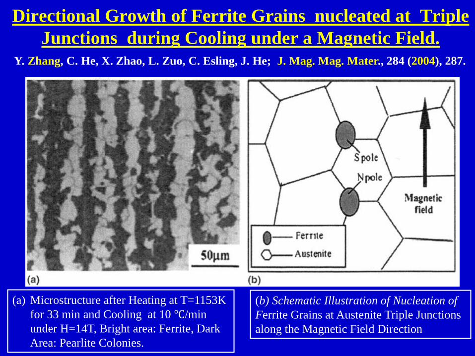
Directional Growth of Ferrite Grains nucleated at Triple
Junctions during Cooling under a Magnetic Field.
(a) Microstructure after Heating at T=1153K
for 33 min and Cooling at 10 ℃/min
under H=14T, Bright area: Ferrite, Dark
Area: Pearlite Colonies.
(b) Schematic Illustration of Nucleation of
Ferrite Grains at Austenite Triple Junctions
along the Magnetic Field Direction
Y. Zhang, C. He, X. Zhao, L. Zuo, C. Esling, J. He; J. Mag. Mag. Mater., 284 (2004), 287.

Effect of Magnetic Field Strength, H, on Ferrite
Elongation in Fe-0.4mass%C AlloyAfter :H.J. Hao, H. Ohtsuka, P. de. Rango, H. Wada; Mater. Trans., 44(2003), 211-213,
“ Quantitative Characterization of the Structural Alignment in Fe-0.4C Alloy
Transformed in High Magn. Fields.”
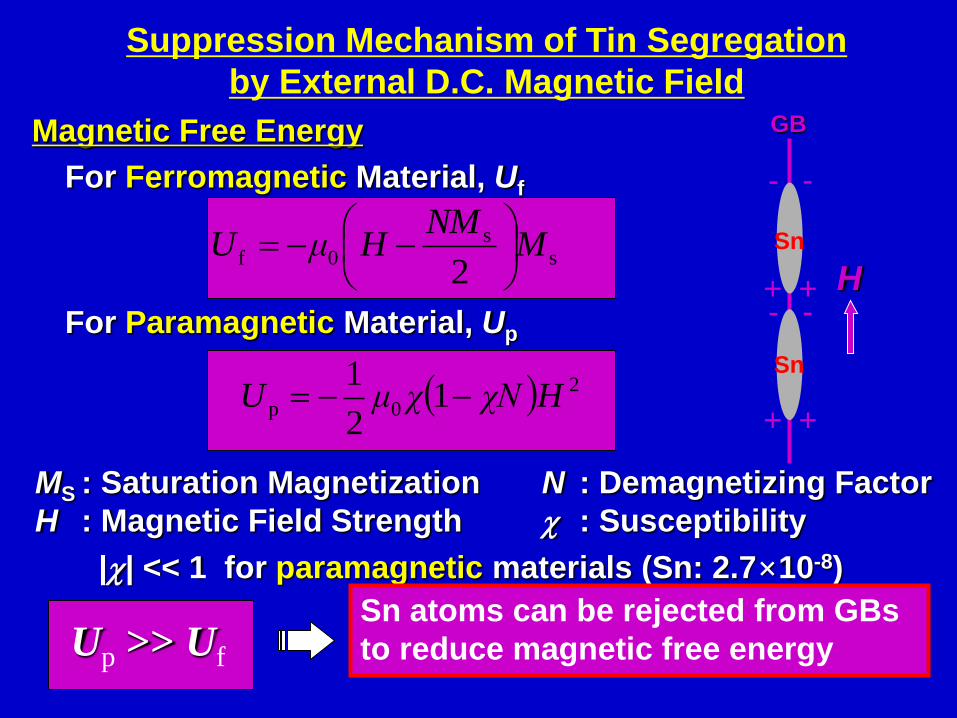
Suppression Mechanism of Tin Segregation
by External D.C. Magnetic Field
ss
0f2
MNM
HμU
=
2
0p 12
1HχNχμU =
MS : Saturation Magnetization N : Demagnetizing Factor
H : Magnetic Field Strength c : Susceptibility
|c| << 1 for paramagnetic materials (Sn: 2.7×10⁻⁸)
Up >> Uf
Magnetic Free Energy
For Ferromagnetic Material, Uf
For Paramagnetic Material, Up
Sn atoms can be rejected from GBs
to reduce magnetic free energy
Sn
Sn
+ +
- -
+ +
- -
H
GB

Control of Segregation-induced Grain Boundary
Brittleness in Fe-Sn Alloy by Magnetic Annealing
S. Tsurekawa, K. Kawahara, K. Okamoto, T. Watanabe, R. Faulkner;
Mater. Sci. Eng., A387-389 (2004), 442.
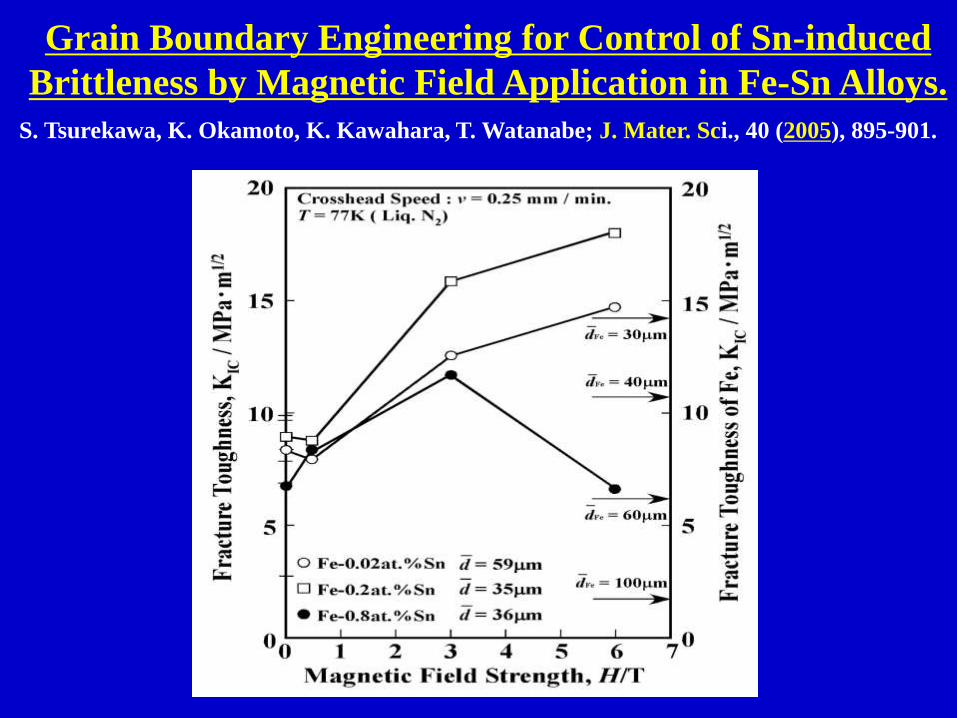
Grain Boundary Engineering for Control of Sn-induced
Brittleness by Magnetic Field Application in Fe-Sn Alloys.
S. Tsurekawa, K. Okamoto, K. Kawahara, T. Watanabe; J. Mater. Sci., 40 (2005), 895-901.

Fe-29.6 at.% Pd Ribbons rapidly Solidified and Annealed at 1173 K.
Grain Boundary Engineering for High Performance
“Ferromagnetic Fe-Pd Shape Memory Alloy”
( Y. Huruya, N.W. Hagood, H.Kimura and T.Watanabe; Mat. Trans. JIM, 39 (1998), 1248-1254.)
“Magnetostriction vs Magnetic Field Strength Characteristics”

Y. Huruya, N.W. Hagood, H.Kimura and T. Watanabe; Mat. Trans. JIM, 39 (1998), 1248-1254.)
Grain Boundary Character Distribution (GBCD) Controlled
Magnetostriction in Fe-29.6 at.%Pd Shape Memory Alloy
As Solidified (RS-1), Annealed (RSA-1) As solidified (RS-2), Annealed (RSA-2)
( Rapidly Solidified at 28.3m/s ) ( Rapidly solidified at 37.3m/s )
Note: The presence of a high density of S3 boundaries degrades the level magnetostriction
in ribbon-shaped specimens of Fe-29.6 at.% Pd ferromagnetic shape memory alloy.

Rejuvenation of Deformation–Induced Cavities by
Magnetic Annealing in Fe-Co Alloy ( T=1023K )
T. Watanabe, S. Nishizawa, S. Tsurekawa: Comlex Inorganic Solids,
Proc. 3rd Intern. Alloy Conf. ( IAC-3), Springer (2005), 327-336.

Generation of A New Function attempted by
“Dislocation and GB-Interface Engineering
Y. Ikuhara: “Nanowire Design by Dislocation Technology”,
Progress in Materials Science, 54 (2009), 770-791.

Herbert Gleiter : Met. Mater. Trans., 40A (2009), 1499-1509
Interface Engineering based on the Electronic Space
Charge at Interphase Boundaries in Nanocomposite.

Space Charge Distribution in a Nanocomposite
consisting of nm-sized Ag and Fe Crystals. At
the Heterophase Boundaries between Ag/Fe-
Crystals Space Charge Regions are Formed.
(a) Space Charge Regions (Gray Areas) in a Metallic
Polycrystal of A and B, the Crystal Size being Large
in comparison to the width of the Space Charge
Regions. (b) Space Charge Regions in a Metallic
Nanocomposite of A and B.
Possible Application of Grain Boundary Engineering
to Functional Materials“Is there a Hidden World of New Materials and Effects
between the Elements of the Periodic Table ?”Herbert Gleiter
Materials Transactions JIM, Vol.44 (2003), Mo.6 1057-1067
Nanostructured Functional Materials


Lecture on Grain Boundary & Interface Engineering
at Department of Materials Engineering, IISc, (No.3)( on 20th November, 2015, Bangalore, India )
Tadao WatanabeLab. of Materials Design and Interface Engineering, Dept. of Nanomechanics,
Graduate School of Engineering, Tohoku University, Sendai, Japan
Guest Scientist, Key Laboratory of Anisotropy and Texture of Materials,
Northeastern University (NEU) , Shenyang, China.
.
Part One: Grain Boundary & Interface Engineering
for Thin Film Materials.
Part Two: Nature-inspired Interface Engineering
for Living Biological Materials

Part One:
Grain Boundary & Interface Engineering
for Thin Film Materials.

How to control the Microstructure in Polycrystals for a Micromechine ?
Polysilicon Gear Train with the Diameter from 128~185mm.
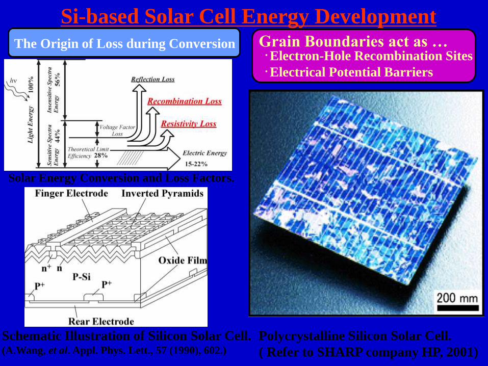
Si-based Solar Cell Energy Development
The Origin of Loss during Conversion
Schematic Illustration of Silicon Solar Cell.(A.Wang, et al. Appl. Phys. Lett., 57 (1990), 602.)
Polycrystalline Silicon Solar Cell.
( Refer to SHARP company HP, 2001)
Grain Boundaries act as …・Electron-Hole Recombination Sites
・Electrical Potential Barriers
Solar Energy Conversion and Loss Factors.

Possible Applications of GBE to Thin Films with
Desirable Properties and High Performance
( Requirements for Thin Films and MEMS materials )
1. Grain Boundary Engineering for Thin Films & Ribbons.
(1) Precise Microstructure Control for High Performance and Reliability.
(2) Enhancement in Fracture Toughness.---W, Mo, Ceramics (Al2O3, SiC, etc.)
(3) Improvement in Wear Resistance. --- Diamond and Ceramic Coatings
(4) Enhancement in Corrosion Resistance.
(5) Development of High Performance---Ferromagnetic Shape-memory Alloys
(6) High Performance Mechanical Flexibility for Polysilicon Solar Cells.
2. Grain Boundary & Interface Engineering for Electro-
Magnetic Ceramics.
(1) Generation of a New function & Multi-functionality.
(2) Improvement of Performance of existing function and properties.
(3) Control of Intrinsic Intergranular Brittleness.

Important Pending Issue of Processing Thin Films “How to control “Abnormal Grain Growth” in Thin Films”
C. V. Thompson; J. Appl. Phys., 58 (1985), 763-772.

Average grain size as a function on annealing time for nanocrystalline Ni annealed
at 693K without and with an external magnetic field (H=6T).
Effect of a Magnetic Field on Late Stage Abnormal Grain Growth
H=6T

Grain Boundary Engineering through Texturing in Au Thin Films:- Surface Energy-Driven Grain Growth and Texture Evolution-
S. Kobayashi, H. Takagi, T. Watanabe: Phil. Mag., (2013)
“Grain boundary character distribution and texture evolution during
surface energy-driven grain growth in nanocrystalline gold thin films”

Grain Boundary Engineering through Texturing in Au Thin Films:- Surface Energy-Driven Grain Growth and Texture Evolution-
S. Kobayashi, H. Takagi, T. Watanabe: Phil. Mag., (2013)
“Grain boundary character distribution and texture evolution during surface
energy-driven grain growth in nanocrystalline gold thin films”

Grain Boundary Microstructure in Au Thin Films
S. Kobayashi, H. Takagi, T. Watanabe: “Grain Boundary Character Distribution and
texture evolution during surface energy-driven grain growth in nanocrystalline
gold thin films”, Phil. Mag. (2013),

Pending Materials Problems to be solved
by GBE in the 21st Century
1. Control of Brittle Fracture which inevitably brings a
serious disaster to human society.
2. Highly reliable and long life Nuclear Reactor Material
to be used for Safe Power Reactor.
3. High performance Photovoltaic Materials to
convert clean Solar Energy to electricity.
4. Establishment of Interface Engineering for
Recyclability of Used or Damaged Materials.
5. Development of a New Multi-functional Material.
6. Interface Engineering for Biological Materials.

Part Two:
Nature-inspired Interface Engineering
for Living Biological Materials
1.Generation of Strong & Tough Materials from
Soft & Weak Components.
2. Generation of A New Function to be applied to
Medical Field.
3. Learning of Versatility of Shapes & Functions
applicable to Interface Engineering.

Different Types of Shell Shape Found in Nature ; Folding and Coiled Structure.
(S.WOLFRAM, “A NEW KIND of SCIENCE”, Wolfam media Inc., 2002.)

1. O. B.Boggild, “The shell structure of the mollusks”, K. Danske Vidensk. Selsk. Skr.
Copenhagen, 2 (1930), 232.
2. J.D.CURREY and A.J.KOHN, “Fracture in the crossed-lamellar structure of Conus shell”,
J. Mater. Sci. 11 (1976), 1615.
3. V. J. Laraia and A.H. Heuer, “Novel Composite Microstructure and Mechanical Behavior of
Mollusk Shell”, J. Am. Ceram. Soc., 11 (1989), 2177.
4. N.V.WILMOT, D.J.BARBER, J.D.TAYLOR and A.L.GRANHAM, “Electron microcopy of
molluscan crossed-lamellar microstructure”, Phil. Trans. R. Soc. Lond. B, 337 (1992), 21.
5. L.T.KUHN-SPEARING, H.KESSLER, E.CHATEAU, R.BALLARINI, A.H.HEUER and
S.M.SPEAEING, “Fracture mechanisms of the Strombus gigas conch shell: implications for
the design of brittle laminates”, J. Mater. Sci., 31 (1996), 6583.
6. S.WEINER and L.ADDADI, “Design strategies in mineralized biological materials”, J. Mater.
Chem., 7(5) (1997), 689.
7. D.CHATEIGNER, C.HEDEGAARD and H.-R.WENK, “Mollusc shell microstructure and
crystallographic textures”, J. Structural Geology, 22 (2000), 1723.
8. Q.L.FENG, F.Z.CUI, G.PU, R.Z.WANG and H.D.LI, “Crystal orientation, toughening
mechanisms and a mimic of nacre”, Mater. Sci. Eng., C11 (2000), 19.
9. R.Z.WANG, Z.SUO, A.G.EVANS, N.YAO and I.A.AKASY, “Deformation mechanisms in
nacre”, J. Mater. Res., 16 (2001), 2485.
10. A.G.EVANS, Z.SUO, R.Z.WANG, I.A.AKASY, M.Y.HE and J.W.HUTCHISON, “Model for
the robust mechanical behavior of nacre”, J. Mater. Sci., 16 (2001), 2475.
11. H.TONG, J.HU, W.MA, G.ZHONG, S.YAO and N.CAO, “In situ analysis of the organic
framework in the prismatic layer of mollusc shell”, Biomaterials, 23 (2002), 2593.
12. F.SONG, X.H.ZHNG and Y.L.BAI, “Microstructure and characteristics in the organic
matrix layers of nacre”, J. Mater. Res., 17 (2002), 1567.
Literature Survey about a microstructure in shells

JOURNAL OF MATERIALS SCIENCE 11 (1976) 1615-1623
Fracture in the crossed-lamellar structure of Conus shellsJ.D.CURREY
Department of Biology, University of York, York, UK
A.J.KOHN
Department of Zoology, University of Washington, Seattle, Washington USA
Crossed-lamellar crystal architecture is the characteristic textural pattern of the calcium carbonate shell
in many kinds of molluscs. By loading specimens from shells of the genus Conus in various orientations
in bending tests it is shown that crossed-lamellar structure is highly anisotropic. This anisotropy is to be
expected from the microscopic and submicroscopic structure, particularly the substructure of the
primary lamellae and their orientation to one another, and from the paths taken by cracks travelling
through layers of different orientation.
Fracture surface of crossed-lamellar
structure.
Schematic of the three layers structure of the
Conus shell.

Our Microstructural and Mechanical Study
on Japanese hard Clam ( “Hamaguri” )
Motivation and Questions
1. Why many types of shells can be robust and tough
to fracture, while they are composed of intrinsically
weak aragonite ( calcium carbonate ) ?
2. How can we toughen brittle materials like ceramics
through control of interfacial micostructure in
biological materials, nature-inspired Interfacial
Engineering ?

Well-Assembled and Crossed-lamellar Microstructure
for Robust Mechanical Properties
of Bioceramic Shell Structure
Tadao WATANABE, Kota KIDO and Sadahiro TSUREKAWALaboratory of Materials Design and Interface Engineering
Department of Machine Intelligence and Systems Engineering
Graduate School of Engineering, Tohoku University, Japan
Outline
1. Importance of the Control of Interfacial Fracture in Brittle Materials.
2. Learning Optimum Microstructure from Natural Bioceramic Structures.
3. SEM Observation of Microstructure in Japanese Clam (Meretrix Lusoria).
4. Hardness and Fracture Toughness Measurements of the Shells with
Crossed-lamellar Microstructure.
5. Conclusion
IUTAM Symposium Marrakesh, Morocco, 2002.

Photograph of Meretrix Lusoria (Japanese hard clam) (a). Schematic
Illustration of Sampling Positions in Meretrix Lusoria shell (b).

High Magnification Observation of Layered Structure
in Japanese Hard Clam (Meretrix Lusoria).

Vickers Hardness as a Function of Young’s Modulus for Various Types of
Brittle Materials. ( I. J. McColm, “Ceramic Hardness”, (1990).)

SEM Micrograph of the middle layer in Japanese Hard Clam
(Meretrix Lusoria) in Spec.2. Three dimensionally network
structure and complicated channel structure in the middle layer .

SEM Micrographs of Japanese Hard Clam (Meretrix Lusoria)
in Spec.2. Enlargement view from the outer layer in Spec.2.
Right hand side is higher magnification micrograph.

Crossed-lamellar Microstructure in the Outer Layer Observed
in Japanese Hard Clam (Meretrix Lusoria).

Schematic Illustrations of (a) Columnar
Nacre/abalone Shell and (b) Sheet
Nacre/pearl Oyster. Polygonal Aragonite
Tablets are adhered into a Lamellar
Structure by a thin Organic Interlayer. In
Columnar Nacre, the Intertablet
Boundaries are correlated into a tesselated
Arrangement. ( R.Z.Wang et al. J. Mster.
Sci., 16 (2001), 2485, Deformation
mechanisms in nacre.)
TEM Micrograph of the Platelets in
Nacre. ( Q.L.Feng et al. Mater. Sci. Eng.,
C11 (2000), 19.)
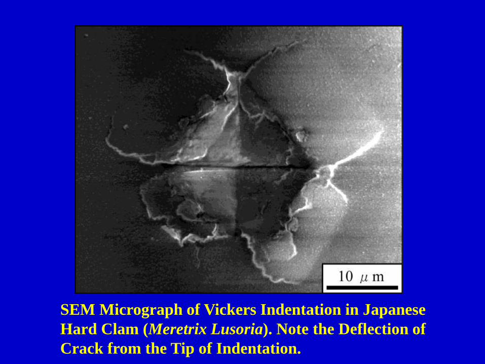
SEM Micrograph of Vickers Indentation in Japanese
Hard Clam (Meretrix Lusoria). Note the Deflection of
Crack from the Tip of Indentation.

(a) Load = 0.5 kgf
Hardness, Hv = 181
KIC = 0.94 MPa・m1/2
(b) Load = 1.0 kgf
Hardness, Hv = 813
KIC = 2.49 MPa・m1/2

α =14 1-84ν -0.5
1+ν
4
K√aα
E
Φ
c
aH
c 18a1.51
0.60.4
0.6IC =( )
Fracture Toughness vs. Hardness Relationship for Japanese
Hard Clam (Meretrix Lusoria).

Fracture Toughness, KIC, plotted against Young’s Modulus, E. ( M.F.Ashby, “Materials
Selection in Mechanical Design” (1992).)
Note: The Data obtained from this work locate at the top level in porous ceramic group.

1. Multi-layered and Crossed-lamellar
microstructures were observed.
2. Fracture Toughness, KIC, determined by
Indentation Technique shows almost top value
among those for Porous Ceramics.
3. Presence of Interfaces between Lamllae plays
important roles in Toughening of Brittle Ceramic
Structure with Crossed-lamellar Microstructure.
4. Crossed-lamellar Microstructure confers Optimal
and Robust Mechanical Property on Natural
Bioceramic Structure.

昆虫の複眼に見られる微細構造と光学機能(Corneal Microstructure of Insects and Optical Performance)

Beilstein J. Nanotechnology, 4 (2013), 292-299.


The Corneal Nipple Nanostructure of
Eye of Mourning Cloak Butterfly

Nipple structure consisting of rows of 5-7 coordination-defects,
with a CSL Superlattice indicated by white circles.

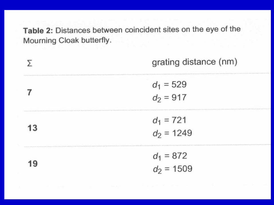
Grain Boundary Character Distribution (GBCD) in Corneal
Nanonipple Structure of Mourning Cloak Butterfly
(Total Number of GBs=73))

Coincidence Site Lattices for S=7, S=13 and S=19


DSC-Lattices formed by interpenetrating (001)
planes of simple Cubic Lattices rotated with
respect to one another by Angle q around [001].
Top: q = 36.9 (S = 5). Bottom: q = 28.1 (S = 17).
The Burgers vectors of the DSC-intrinsic
dislocations are shown at the center of each
diagram.
Observed Primary Relaxation Spacing, d, and
Secondary Relaxation Spacing, ds, in [001] Twist
Boundaries in Gold as a Function of Twist Angle q.
Displacement Shift Complete
( DSC ) Lattice Model
R. W. Balluffi: “Grain Boundary Structure
and Segregation”, Interfacial Segregation,
ASM., (1979), 193-237.


(1) . J.W.C. Dunlop, R. Weikamer, P. Fratzl:
Materials Today, 14 (2011), No.3, 70-78
“Artful Interfaces within Biological Materials”
(2). P. Fratzl, R. Weinkamer:
Progress in Materials Science, 52 (2007), 1263-1334,
“ Nature’s Hierachical Materials”
(3). J.W.C. Dunlop, P. Fratzl: Ann. Rev. Mater. Res.,
40 (2010), 1-24,
“Biological Composites”
Important Literature & Reviews on Interface
Engineering of Biological Materials.

Fig. 1. Description on an Imaginary Scale of the Evolution of the Innovation Content of Materials.
Interfacial Engineering – a PerspectiveE. D. Hondros; Materials Science and Engineering, A 166 (1993), 1-10.

Summary
1. Structure-dependent properties of grain boundaries are thesource of function and performance in polycrystallinematerials. Some grain boundaries can be active, but others areinactive in function-generating metallurgical phenomena. Ithas been well evidenced at the end of last century that GrainBoundary and Interface Engineering can confer desirablemechanical properties and high performance to a “PolycrystalSystem” by designing and controlling of the grain boundarymicrostructure.
2. Now we are facing the Second stage of Grain Boundary andInterface Engineering to produce a New type of “Structural orFunctional Material” not replaceable by any existing ones.Nanostructured materials and Thin Films with an extremelyhigh density of Interfaces are on one side, but there is a strongdemand for “Low-dimension GBE” which may be also one ofthe targets of MEMS, together with “Further Improvement inPerformance of Conventional materials”, in the 21st century.

3. In near future, the third stage of Grain Boundary and Interface
Engineering will be coming which may bring about a such New
types of “Structural or Functional Material” only those living
creatures like plants, animals and living cells can exhibit their
function and performance those are never produced and
demonstrated by presently existing Materials Science and
Engineering. For this purpose, a new challenge awaits those
who are given their original insight into a possibility to create
a new function and excellent performance unpredictable from
our current scientific knowledge. Multi-disciplinary knowledge
of Materials Science and Engineering, including Living Organic
Materials may open a New Era of Interface-controlled Materials
with a amazing function and performance.

Thank you for kind Attention and
Interest in Grain Boundary Engineering

Why were Peoples so much attracted by Studies
of GBs and Interfaces and involved in them ?
Proc. Intern. School on “Grain Boundaries” held at Ecole Polytechnique, Canada, 1973

December, 2002

To celebrate our great Pioneer in GB research field !!
Dr. Donald McLean who had 100th Birthday on July 25, 2015

D. A. Smith Y. IshidaT. Watanabe (1996)


Relation between Toughness and Modulus for
Natural Materials

Memorium
Yoichi Ishida (1935 – 1996)
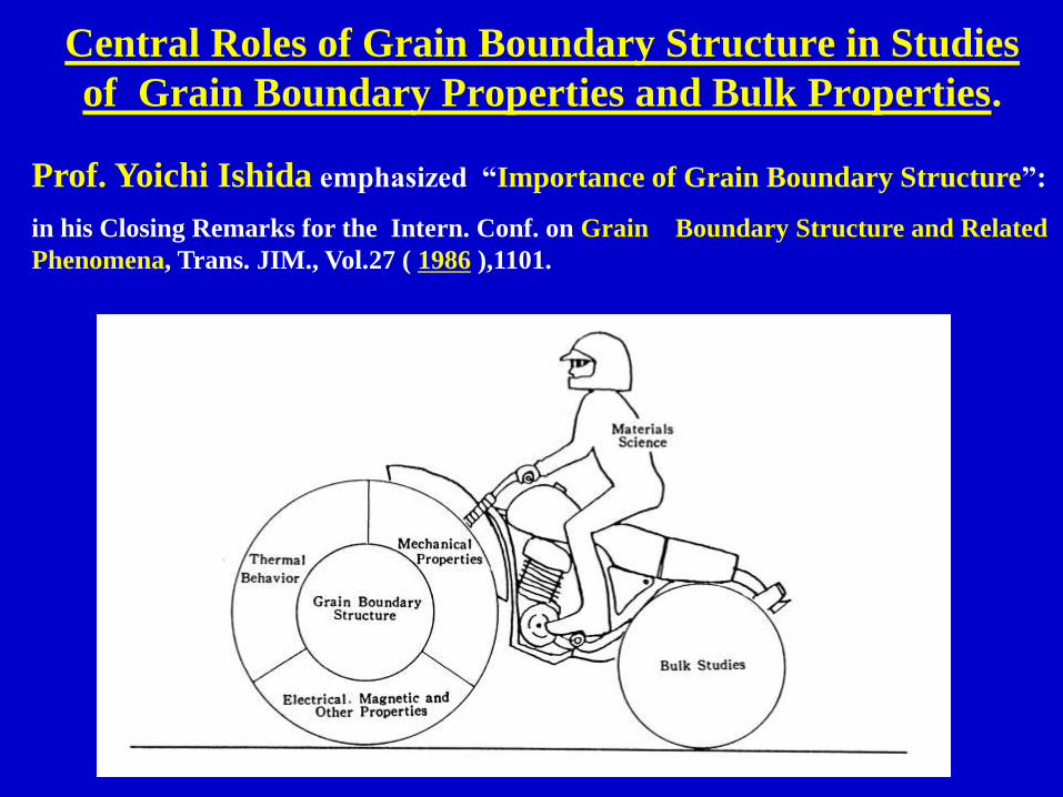
Central Roles of Grain Boundary Structure in Studies
of Grain Boundary Properties and Bulk Properties.
Prof. Yoichi Ishida emphasized “Importance of Grain Boundary Structure”:
in his Closing Remarks for the Intern. Conf. on Grain Boundary Structure and Related
Phenomena, Trans. JIM., Vol.27 ( 1986 ),1101.

Thickness Effect on the Flow Stress in Polycrystalline
Materials with Various Grain Sizes( S. Miyazaki, K, Shibata & H. Fujita: Acta Met., 27(1979), 855-862 )

Grain Boundary Intersecting a Tungsten Specimen. (J.
Hren)
Diagrams of Structure of Twist Type
Boundary in Field Ion Emission.
( M. A. Fortes )
Observations on Atomistic Structure of Grain Boundaries by
Field-Ion Microscopy (FIM)
K. M. Bowkett and D. A. Smith : Field Ion Microscopy, North-Holland (1970)

The grain-boundary critical current density Jc
normalized by the average value for two grains
at 4.2-5K as a function of the misorientation
angle in the basal plane in YBCO.
D. Dimos, et al. Phys. Rev. Lett., 61 (1988), 219.
Misfit angle Dq dependence of Resistance-
Temperature Characteristic of S = 3 Boundary
with and without misfit angle.
K. Hayashi, T. Yamamoto and T. Sakuma, J.
Am. Ceram. Soc., 79 (1996), 1669.
Electrical Properties of Grain Boundaries
Critical Current Density Jc of YBCO PTCR Characteristic of SrTiO3

Transport Properties controlled by Grain
Boundary Microstructure of YBCO
C. E. Ecom, J. M. Phillips, A.E. Marshall, T.H. Geballe; Interface Science, 1 (1993), 267.
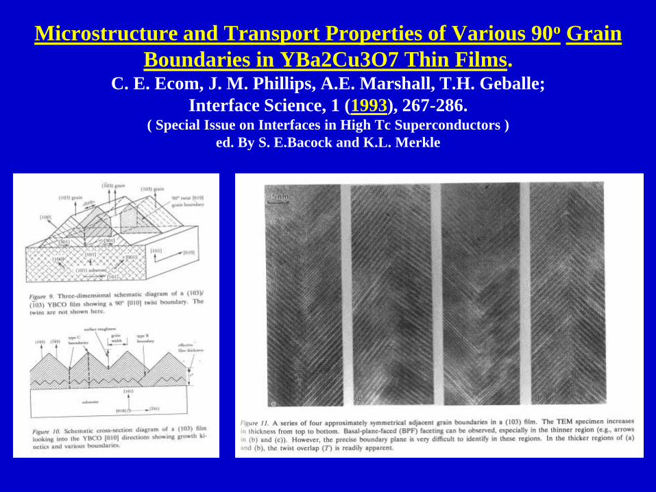
Microstructure and Transport Properties of Various 90o Grain
Boundaries in YBa2Cu3O7 Thin Films.C. E. Ecom, J. M. Phillips, A.E. Marshall, T.H. Geballe;
Interface Science, 1 (1993), 267-286.( Special Issue on Interfaces in High Tc Superconductors )
ed. By S. E.Bacock and K.L. Merkle

Conclusions
In order to study optimal Microstructure and Mechanical properties
in Brittle Bioceramic Structure, Japanese Hard Clam consisted of
Aragonite was studied.
1. Multi-layered and Crossed-lamellar microstructures were
observed.
2. Fracture Toughness, KIC, determined by Indentation Technique
shows almost top value among those for Porous Ceramics.
3. Presence of Interfaces between Lamllae plays important roles in
Toughening of Brittle Ceramic Structure with Crossed-lamellar
Microstructure.
4. Crossed-lamellar Microstructure confers Optimal and Robust
Mechanical Property on Natural Bioceramic Structure.