Embed Size (px)
Citation preview

© 2014 Pearson Education, Inc.
This work is protected by United States copyright laws and is provided solely for the use of instructors in teaching their courses and assessing student learning. Dissemination or sale of any part of this work (including on the World Wide Web) will destroy the integrity of the work and is not permitted. The work and materials from it should never be made available to students except by instructors using the accompanying text in their classes. All recipients of this work are expected to abide by these restrictions and to honor the intended pedagogical purposes and the needs of other instructors who rely on these materials.
Lecture PowerPoints
Chapter 21 Physics: Principles with Applications, 7th edition
Giancoli
Chapter 21 Electromagnetic Induction and
Faraday’s Law
© 2014 Pearson Education, Inc.

Contents of Chapter 21
• Induced EMF
• Faraday’s Law of Induction; Lenz’s Law
• EMF Induced in a Moving Conductor
• Changing Magnetic Flux Produces an Electric Field
• Electric Generators
© 2014 Pearson Education, Inc.

Contents of Chapter 21
• Back EMF and Counter Torque; Eddy Currents
• Transformers and Transmission of Power
• Information Storage: Magnetic and Semiconductor; Tape, Hard Drive, RAM
• Applications of Induction: Microphone, Seismograph, GFCI
• Inductance
© 2014 Pearson Education, Inc.

Contents of Chapter 21
• Energy Stored in a Magnetic Field
• LR Circuit
• AC Circuits and Reactance
• LRC Series AC Circuit
• Resonance in AC Circuits
© 2014 Pearson Education, Inc.

21-1 Induced EMF
Almost 200 years ago, Faraday looked for evidence that a magnetic field would induce an electric current with this apparatus:
© 2014 Pearson Education, Inc.

21-1 Induced EMF
He found no evidence when the current through the left-hand loop was steady, but did see a current induced in the right-hand loop when the switch was turned on or off.
© 2014 Pearson Education, Inc.

21-1 Induced EMF
In addition, a current will be induced in a wire loop if a magnet is moved through the loop, but not when the magnet is held steady.
© 2014 Pearson Education, Inc.

21-1 Induced EMF
Therefore, a changing magnetic field induces an emf.
Faraday’s experiment used a magnetic field that was changing because the current producing it was changing; the previous graphic shows a magnetic field that is changing because the magnet is moving.
© 2014 Pearson Education, Inc.

21-2 Faraday’s Law of Induction; Lenz’s Law
The induced emf in a wire loop is proportional to the rate of change of magnetic flux through the loop.
Magnetic flux:
Unit of magnetic flux: weber, Wb.
1 Wb = 1 T·m2
© 2014 Pearson Education, Inc.
(21-1)

21-2 Faraday’s Law of Induction; Lenz’s Law
This drawing shows the variables in the flux equation:
© 2014 Pearson Education, Inc.

21-2 Faraday’s Law of Induction; Lenz’s Law
The magnetic flux is analogous to the electric flux—it is proportional to the total number of lines passing through the loop.
© 2014 Pearson Education, Inc.
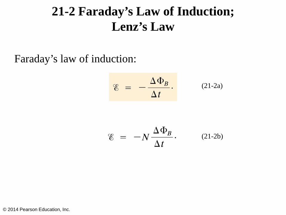
21-2 Faraday’s Law of Induction; Lenz’s Law
Faraday’s law of induction:
© 2014 Pearson Education, Inc.
(21-2a)
(21-2b)

21-2 Faraday’s Law of Induction; Lenz’s Law
The minus sign gives the direction of the induced emf:
A current produced by an induced emf moves in a direction so that the magnetic field it produces tends to restore the changed field.
© 2014 Pearson Education, Inc.

21-2 Faraday’s Law of Induction; Lenz’s Law
Magnetic flux will change if the area of the loop changes:
© 2014 Pearson Education, Inc.
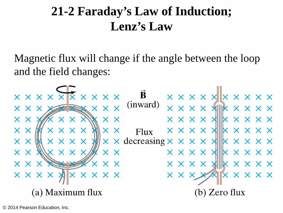
21-2 Faraday’s Law of Induction; Lenz’s Law
Magnetic flux will change if the angle between the loop and the field changes:
© 2014 Pearson Education, Inc.

21-2 Faraday’s Law of Induction; Lenz’s Law
Problem Solving: Lenz’s Law
1. Determine whether the magnetic flux is increasing, decreasing, or unchanged.
2. The magnetic field due to the induced current points in the opposite direction to the original field if the flux is increasing; in the same direction if it is decreasing; and is zero if the flux is not changing.
3. Use the right-hand rule to determine the direction of the current.
4. Remember that the external field and the field due to the induced current are different.
© 2014 Pearson Education, Inc.

21-3 EMF Induced in a Moving Conductor
This image shows another way the magnetic flux can change:
© 2014 Pearson Education, Inc.

21-3 EMF Induced in a Moving Conductor
The induced current is in a direction that tends to slow the moving bar—it will take an external force to keep it moving.
© 2014 Pearson Education, Inc.

21-3 EMF Induced in a Moving Conductor
The induced emf has magnitude
Measurement of blood velocity from induced emf:
© 2014 Pearson Education, Inc.
(21-3)

21-4 Changing Magnetic Flux Produces an Electric Field
A changing magnetic flux induces an electric field; this is a generalization of Faraday’s law. The electric field will exist regardless of whether there are any conductors around.
© 2014 Pearson Education, Inc.

21-5 Electric Generators
A generator is the opposite of a motor—it transforms mechanical energy into electrical energy. This is an ac generator:
The axle is rotated by an external force such as falling water or steam. The brushes are in constant electrical contact with the slip rings.
© 2014 Pearson Education, Inc.

21-5 Electric Generators
A dc generator is similar, except that it has a split-ring commutator instead of slip rings.
© 2014 Pearson Education, Inc.

21-5 Electric Generators
A sinusoidal emf is induced in the rotating loop (N is the number of turns, and A the area of the loop):
© 2014 Pearson Education, Inc.
(21-5)

21-6 Back EMF and Counter Torque; Eddy Currents
An electric motor turns because there is a torque on it due to the current. We would expect the motor to accelerate unless there is some sort of drag torque.
That drag torque exists, and is due to the induced emf, called a back emf.
© 2014 Pearson Education, Inc.

21-6 Back EMF and Counter Torque; Eddy Currents
A similar effect occurs in a generator—if it is connected to a circuit, current will flow in it, and will produce a counter torque. This means the external applied torque must increase to keep the generator turning.
© 2014 Pearson Education, Inc.

21-6 Back EMF and Counter Torque; Eddy Currents
Induced currents can flow in bulk material as well as through wires. These are called eddy currents, and can dramatically slow a conductor moving into or out of a magnetic field.
© 2014 Pearson Education, Inc.
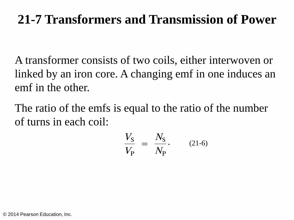
21-7 Transformers and Transmission of Power
A transformer consists of two coils, either interwoven or linked by an iron core. A changing emf in one induces an emf in the other.
The ratio of the emfs is equal to the ratio of the number of turns in each coil:
© 2014 Pearson Education, Inc.
(21-6)

21-7 Transformers and Transmission of Power
This is a step-up transformer—the emf in the secondary coil is larger than the emf in the primary:
© 2014 Pearson Education, Inc.

21-7 Transformers and Transmission of Power
Energy must be conserved; therefore, in the absence of losses, the ratio of the currents must be the inverse of the ratio of turns:
© 2014 Pearson Education, Inc.
(21-7)

21-7 Transformers and Transmission of Power
Transformers work only if the current is changing; this is one reason why electricity is transmitted as ac.
© 2014 Pearson Education, Inc.

21-8 Information Storage: Magnetic and Semiconductor; Tape, Hard Drive, RAM
Magnetic tape and computer hard drives store information by magnetizing small areas on a ferromagnetic coating. The information may be encoded in either digital or analog form.
© 2014 Pearson Education, Inc.

21-8 Information Storage: Magnetic and Semiconductor; Tape, Hard Drive, RAM
Random access memory (RAM) is used to store information in computers and other digital devices. The binary bits are stored as electric charges or voltages, and are either off or on (“0” or “1”). A common type of RAM is dynamic random access memory, or DRAM, based on transistors called MOSFETs (metal oxide semiconductor field effect transistors).
© 2014 Pearson Education, Inc.

21-8 Information Storage: Magnetic and Semiconductor; Tape, Hard Drive, RAM
This image shows how a DRAM array works. The bit lines are either on or off, and the word lines allow the bits to be read and written. This is a 2×2 array of MOSFETs.
© 2014 Pearson Education, Inc.

21-8 Information Storage: Magnetic and Semiconductor; Tape, Hard Drive, RAM
The DRAM array loses its information if the power goes off—it is called volatile. Some memory needs to be nonvolatile; this diagram shows a chip that is able to preserve its state even without power.
© 2014 Pearson Education, Inc.

21-9 Applications of Induction: Microphone, Seismograph, GFCI
This microphone works by induction; the vibrating membrane induces an emf in the coil
© 2014 Pearson Education, Inc.

21-9 Applications of Induction: Microphone, Seismograph, GFCI
A seismograph has a fixed coil and a magnet hung on a spring (or vice versa), and records the current induced when the earth shakes.
© 2014 Pearson Education, Inc.

21-9 Applications of Induction: Microphone, Seismograph, GFCI
A ground fault circuit interrupter (GFCI) will interrupt the current to a circuit that has shorted out in a very short time, preventing electrocution.
© 2014 Pearson Education, Inc.

21-10 Inductance
Mutual inductance: a changing current in one coil will induce a current in a second coil.
And vice versa; note that the constant M, known as the mutual inductance, is the same:
© 2014 Pearson Education, Inc.
(21-8a)
(21-8b)

21-10 Inductance
Unit of inductance: the henry, H.
1 H = 1 V·s/A = 1 Ω·s
A transformer is an example of mutual inductance.
© 2014 Pearson Education, Inc.

21-10 Inductance
A changing current in a coil will also induce an emf in the same coil:
Here, L is called the self-inductance.
© 2014 Pearson Education, Inc.
(21-9)
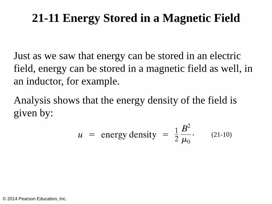
21-11 Energy Stored in a Magnetic Field
Just as we saw that energy can be stored in an electric field, energy can be stored in a magnetic field as well, in an inductor, for example.
Analysis shows that the energy density of the field is given by:
© 2014 Pearson Education, Inc.
(21-10)

21-12 LR Circuit
A circuit consisting of an inductor and a resistor will begin with most of the voltage drop across the inductor, as the current is changing rapidly. With time, the current will increase less and less, until all the voltage is across the resistor.
© 2014 Pearson Education, Inc.

21-12 LR Circuit
This plot shows the current as a function of time in an LR circuit that has just been connected across an emf.
© 2014 Pearson Education, Inc.

21-12 LR Circuit
If the circuit is then shorted across the battery, the current will gradually decay away.
© 2014 Pearson Education, Inc.

21-13 AC Circuits and Reactance
Resistors, capacitors, and inductors have different phase relationships between current and voltage when placed in an ac circuit.
The current through a resistor is in phase with the voltage.
© 2014 Pearson Education, Inc.
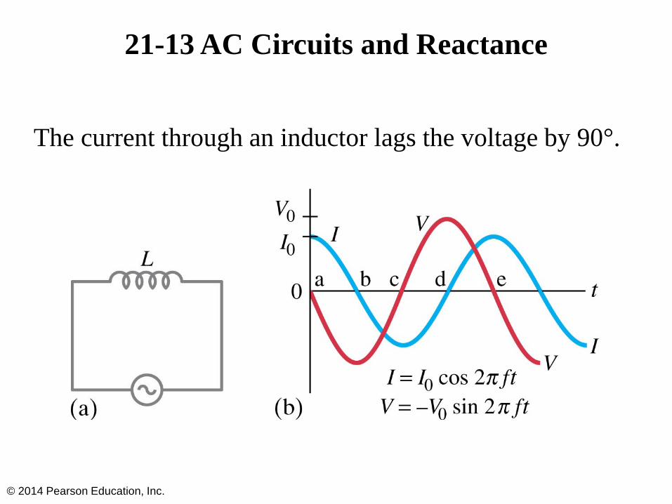
21-13 AC Circuits and Reactance
The current through an inductor lags the voltage by 90°.
© 2014 Pearson Education, Inc.

21-13 AC Circuits and Reactance
In a capacitor, the current leads the voltage by 90°.
© 2014 Pearson Education, Inc.

21-13 AC Circuits and Reactance
Both the inductor and capacitor have an effective resistance (ratio of voltage to current), called the reactance.
Inductor:
Capacitor:
Note that both depend on frequency.
© 2014 Pearson Education, Inc.
(21-11b)
(21-12b)

21-14 LRC Series AC Circuit
Analyzing the LRC series AC circuit is complicated, as the voltages are not in phase—this means we cannot simply add them. Furthermore, the reactances depend on the frequency.
© 2014 Pearson Education, Inc.

21-14 LRC Series AC Circuit
We calculate the voltage (and current) using what are called phasors—these are vectors representing the individual voltages.
Here, at t = 0, the current and voltage are both at a maximum. As time goes on, the phasors will rotate counterclockwise.
© 2014 Pearson Education, Inc.

21-14 LRC Series AC Circuit
Some time t later, the phasors have rotated.
© 2014 Pearson Education, Inc.

21-14 LRC Series AC Circuit
The voltages across each device are given by the x-component of each, and the current by its x-component. The current is the same throughout the circuit.
© 2014 Pearson Education, Inc.

21-14 LRC Series AC Circuit
We find from the ratio of voltage to current that the effective resistance, called the impedance, of the circuit is given by:
© 2014 Pearson Education, Inc.
(21-15)

21-15 Resonance in AC Circuits
The rms current in an ac circuit is:
Clearly, Irms depends on the frequency.
© 2014 Pearson Education, Inc.
(21-18)
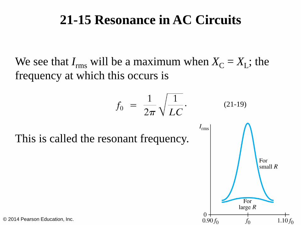
21-15 Resonance in AC Circuits
We see that Irms will be a maximum when XC = XL; the frequency at which this occurs is
This is called the resonant frequency.
© 2014 Pearson Education, Inc.
(21-19)

Summary of Chapter 21
• Magnetic flux:
• Changing magnetic flux induces emf:
• Induced emf produces current that opposes original flux change
• Changing magnetic field produces an electric field
• Electric generator changes mechanical energy to electrical energy; electric motor does the opposite
© 2014 Pearson Education, Inc.

Summary of Chapter 21
• Transformer uses induction to change voltage:
• Mutual inductance:
• Energy density stored in magnetic field:
• LRC series circuit:
© 2014 Pearson Education, Inc.