Embed Size (px)
Citation preview

8/22/2019 Lecture Ultrasound Beams
http://slidepdf.com/reader/full/lecture-ultrasound-beams 1/126
Transducers

8/22/2019 Lecture Ultrasound Beams
http://slidepdf.com/reader/full/lecture-ultrasound-beams 2/126
Ultrasound is produced and detectedwith a transducer, composed of one or
more ceramic elements withelectromechanical (piezoelectric)properties.• The ceramic element converts electrical
energy into mechanical energy to produceultrasound and mechanical energy intoelectrical energy for ultrasound detection.

8/22/2019 Lecture Ultrasound Beams
http://slidepdf.com/reader/full/lecture-ultrasound-beams 3/126
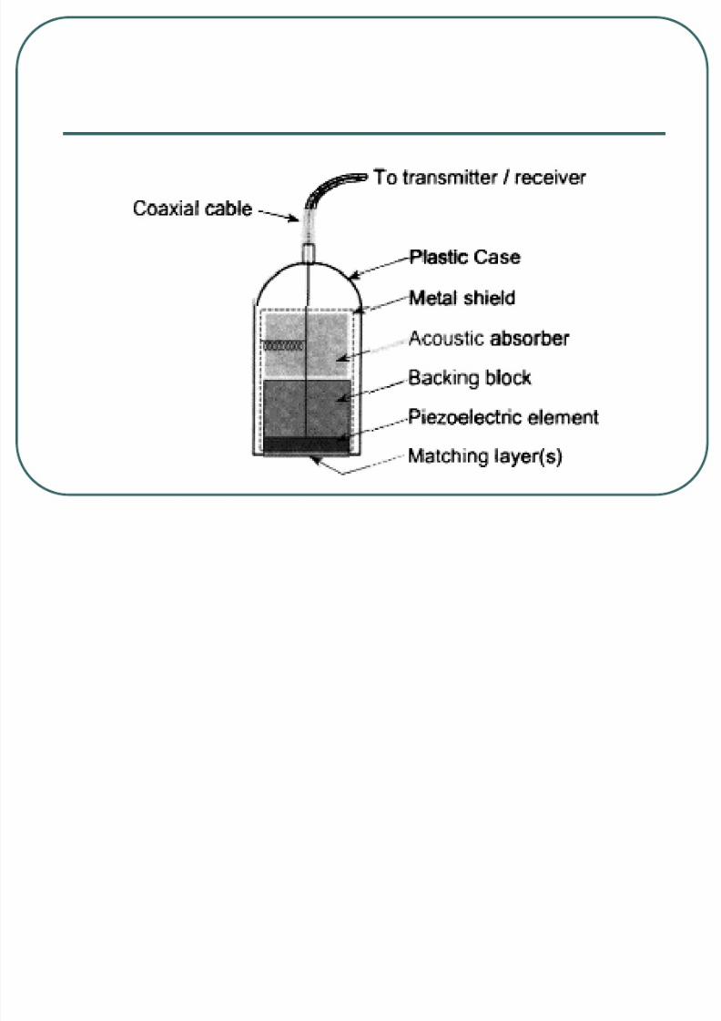
Over the past several decades, the transducer assembly has evolved considerably in design,function, and capability, from a single-elementresonance crystal to a broadband transducer
array of hundreds of individual elements.• A simple single-element, plane-piston source
transducer has major components including the• piezoelectric material,
• marching layer,
• backing block,• acoustic absorber,
• insulating cover,
• sensor electrodes, and
• transducer housing.
8/22/2019 Lecture Ultrasound Beams
http://slidepdf.com/reader/full/lecture-ultrasound-beams 4/126

8/22/2019 Lecture Ultrasound Beams
http://slidepdf.com/reader/full/lecture-ultrasound-beams 5/126
Piezoelectric Materials
A piezoelectric material (often a crystal
or ceramic) is the functional component
of the transducer.• It converts electrical energy into mechanical
(sound) energy by physical deformation of the
crystal structure.

8/22/2019 Lecture Ultrasound Beams
http://slidepdf.com/reader/full/lecture-ultrasound-beams 6/126
ConverseIy, mechanical pressure
applied to its surface creates electrical
energy.• Piezoelectric materials are characterized by a
well-defined molecular arrangement of
electrical dipoles (Fig. 16-9).
8/22/2019 Lecture Ultrasound Beams
http://slidepdf.com/reader/full/lecture-ultrasound-beams 7/126
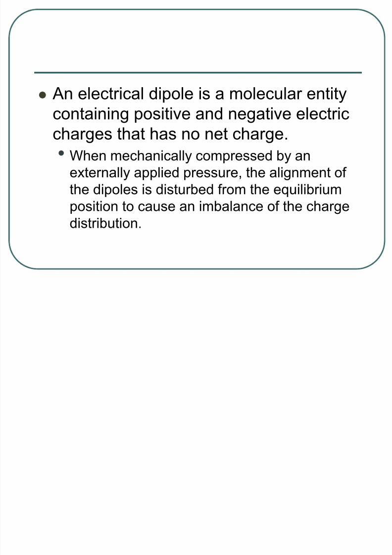
An electrical dipole is a molecular entity
containing positive and negative electric
charges that has no net charge.• When mechanically compressed by an
externally applied pressure, the alignment of
the dipoles is disturbed from the equilibrium
position to cause an imbalance of the chargedistribution.

8/22/2019 Lecture Ultrasound Beams
http://slidepdf.com/reader/full/lecture-ultrasound-beams 8/126
A potential difference (voltage) is created
across the element with one surface
maintaining a net positive charge andone surface a net negative charge.
• Surface electrodes measure the voltage,
which is proportional to the incident
mechanical pressure amplitude.

8/22/2019 Lecture Ultrasound Beams
http://slidepdf.com/reader/full/lecture-ultrasound-beams 9/126
Conversely, application of an external
voltage through conductors attached to
the surface electrodes induces themechanical expansion and contraction of
the transducer element.

8/22/2019 Lecture Ultrasound Beams
http://slidepdf.com/reader/full/lecture-ultrasound-beams 10/126
There are natural and syntheticpiezoelectric materials.
• An example of a natural piezoelectric materialis quartz crystal, commonly used in watchesand other time pieces to provide a mechanicalvibration source at 32.768 kHz for intervaltiming.
• This is one of several oscillation frequencies of quartz, determined by the crystal cut andmachining properties.

8/22/2019 Lecture Ultrasound Beams
http://slidepdf.com/reader/full/lecture-ultrasound-beams 11/126
Ultrasound transducers for medical imagingapplications employ a synthetic piezoelectricceramic, most often lead-zirconate-titanate
(PZT).• The piezoelectric attributes are attained after aprocess of • Molecular synthesis,
• Heating,
• Orientation of internal dipole structures with an appliedexternal voltage,
• Cooling to permanently maintain the dipole orientation,and
• Cutting into a specific shape.

8/22/2019 Lecture Ultrasound Beams
http://slidepdf.com/reader/full/lecture-ultrasound-beams 12/126
For PZT in its natural state, no piezoelectric
properties are exhibited; however, heating the
material past its “Curie temperature” (i.e., 3280
C to 3650 C ) and applying an external voltage
causes the dipoles to align in the ceramic.
• The external voltage is maintained until the material
has cooled to below its Curie temperature.
• Once the material has cooled, the dipoles retain their
alignment.
8/22/2019 Lecture Ultrasound Beams
http://slidepdf.com/reader/full/lecture-ultrasound-beams 13/126
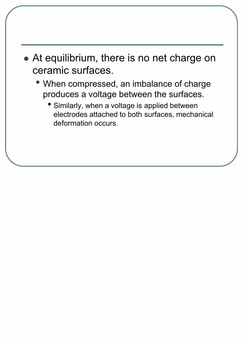
At equilibrium, there is no net charge on
ceramic surfaces.
• When compressed, an imbalance of chargeproduces a voltage between the surfaces.
• Similarly, when a voltage is applied between
electrodes attached to both surfaces, mechanical
deformation occurs.

8/22/2019 Lecture Ultrasound Beams
http://slidepdf.com/reader/full/lecture-ultrasound-beams 14/126
The piezoelectric element is composed
of aligned molecular dipoles.
8/22/2019 Lecture Ultrasound Beams
http://slidepdf.com/reader/full/lecture-ultrasound-beams 15/126
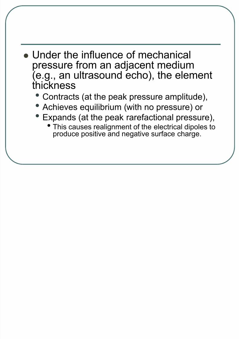
Under the influence of mechanicalpressure from an adjacent medium(e.g., an ultrasound echo), the element
thickness• Contracts (at the peak pressure amplitude),
• Achieves equilibrium (with no pressure) or
• Expands (at the peak rarefactional pressure),
• This causes realignment of the electrical dipoles toproduce positive and negative surface charge.

8/22/2019 Lecture Ultrasound Beams
http://slidepdf.com/reader/full/lecture-ultrasound-beams 16/126

8/22/2019 Lecture Ultrasound Beams
http://slidepdf.com/reader/full/lecture-ultrasound-beams 17/126
Surface electrodes (not shown)
measure the voltage as a function of
time.

8/22/2019 Lecture Ultrasound Beams
http://slidepdf.com/reader/full/lecture-ultrasound-beams 18/126
An external voltage source applied to the
element surfaces causes compression or
expansion from equilibrium byrealignment of the dipoles in response to
the electrical attraction or repulsion
force.

8/22/2019 Lecture Ultrasound Beams
http://slidepdf.com/reader/full/lecture-ultrasound-beams 19/126

8/22/2019 Lecture Ultrasound Beams
http://slidepdf.com/reader/full/lecture-ultrasound-beams 20/126
Resonance Transducers
Resonance transducers for pulse echoultrasound imaging are manufactured tooperate in a “resonance” mode, whereby a
voItage (commonly 150 V) of very shortduration (a voltage spike of 1 msec) is applied,causing the piezoelectric material to initiallycontract, and subsequently vibrate at a natural
resonance frequency.• This frequency is selected by the “thickness cut,” dueto the preferential emission of ultrasound waveswhose wavelength is twice the thickness of thepiezoelectric material.

8/22/2019 Lecture Ultrasound Beams
http://slidepdf.com/reader/full/lecture-ultrasound-beams 21/126
The operating frequency is determined
from the speed of sound in, and the
thickness of, the piezoelectric material.• For example, a 5-MHz transducer will have a
wavelength in PZT (speed of sound in PZT is
4,000 m/sec) of
mmmetersm
f
c80.0108
sec/105
sec/4000 4
6

8/22/2019 Lecture Ultrasound Beams
http://slidepdf.com/reader/full/lecture-ultrasound-beams 22/126
A short duration
voltage spike causes
the resonance
piezoelectric elementto vibrate at its
natural frequency, f o,
which is determined
by the thickness of the transducer equal
to 1/A.
8/22/2019 Lecture Ultrasound Beams
http://slidepdf.com/reader/full/lecture-ultrasound-beams 23/126
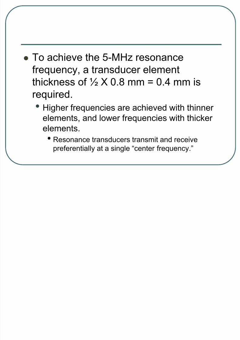
To achieve the 5-MHz resonance
frequency, a transducer element
thickness of ½ X 0.8 mm = 0.4 mm isrequired.
• Higher frequencies are achieved with thinner
elements, and lower frequencies with thicker
elements.• Resonance transducers transmit and receive
preferentially at a single “center frequency.”

8/22/2019 Lecture Ultrasound Beams
http://slidepdf.com/reader/full/lecture-ultrasound-beams 24/126
Damping Block
The damping block, layered on the back of the
piezoelectric element, absorbs the backward
directed ultrasound energy and attenuates
stray ultrasound signals from the housing.
• This component also dampens he transducer vibration
in create an ultrasound pulse width a short spatial
pulse length, which is necessary to preserve detail
along he beam axis (axial resolution).

8/22/2019 Lecture Ultrasound Beams
http://slidepdf.com/reader/full/lecture-ultrasound-beams 25/126

8/22/2019 Lecture Ultrasound Beams
http://slidepdf.com/reader/full/lecture-ultrasound-beams 26/126

8/22/2019 Lecture Ultrasound Beams
http://slidepdf.com/reader/full/lecture-ultrasound-beams 27/126

8/22/2019 Lecture Ultrasound Beams
http://slidepdf.com/reader/full/lecture-ultrasound-beams 28/126
Dampening of the vibration (also knownas “ring-down”) lessens the purity of theresonance frequency and introduces abroadband frequency spectrum.• With ring-down, an increase in he bandwidth
(range of frequencies) of he ultrasound pulseoccurs by introducing higher and lower frequencies above and below the center (resonance) frequency.

8/22/2019 Lecture Ultrasound Beams
http://slidepdf.com/reader/full/lecture-ultrasound-beams 29/126
The “Q factor” describes the bandwidth of the
sound emanating from a transducer as
where f o is the center frequency and the
bandwidth is the width of the frequencydistribution.
Bandwidth
f Q o
8/22/2019 Lecture Ultrasound Beams
http://slidepdf.com/reader/full/lecture-ultrasound-beams 30/126
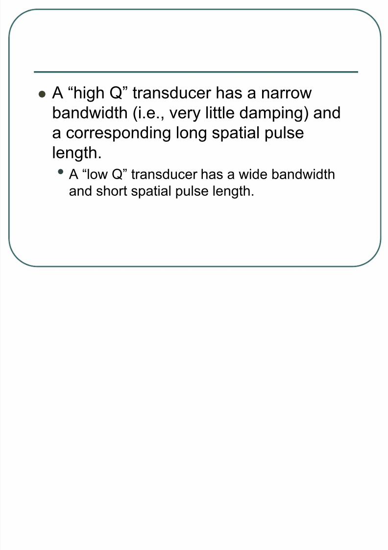
A “high Q” transducer has a narrow
bandwidth (i.e., very little damping) and
a corresponding long spatial pulselength.
• A “low Q” transducer has a wide bandwidth
and short spatial pulse length.

8/22/2019 Lecture Ultrasound Beams
http://slidepdf.com/reader/full/lecture-ultrasound-beams 31/126
Imaging applications require a broadbandwidth transducer in order to achievehigh spatial resolution along the directionof beam travel.• Blood velocity measurements by Doppler
instrumentation require a relatively narrow-band transducer response in order topreserve velocity information encoded bychanges in the echo frequency relative to theincident frequency.
8/22/2019 Lecture Ultrasound Beams
http://slidepdf.com/reader/full/lecture-ultrasound-beams 32/126
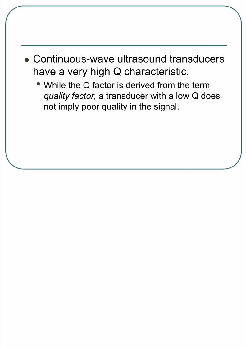
Continuous-wave ultrasound transducers
have a very high Q characteristic.
• While the Q factor is derived from the termquality factor, a transducer with a low Q does
not imply poor quality in the signal.

8/22/2019 Lecture Ultrasound Beams
http://slidepdf.com/reader/full/lecture-ultrasound-beams 33/126
Matching Layer
The matching layer provides the interfacebetween the transducer element and the tissueand minimizes the acoustic impedance
differences between the transducer and thepatient.• It consists of layers of materials with acoustic
impedances that are intermediate to those of softtissue and the transducer material.
• The thickness of each layer is equal to one-fourth thewavelength, determined from the center operatingfrequency of the transducer and speed of sound in thematching layer.
8/22/2019 Lecture Ultrasound Beams
http://slidepdf.com/reader/full/lecture-ultrasound-beams 34/126
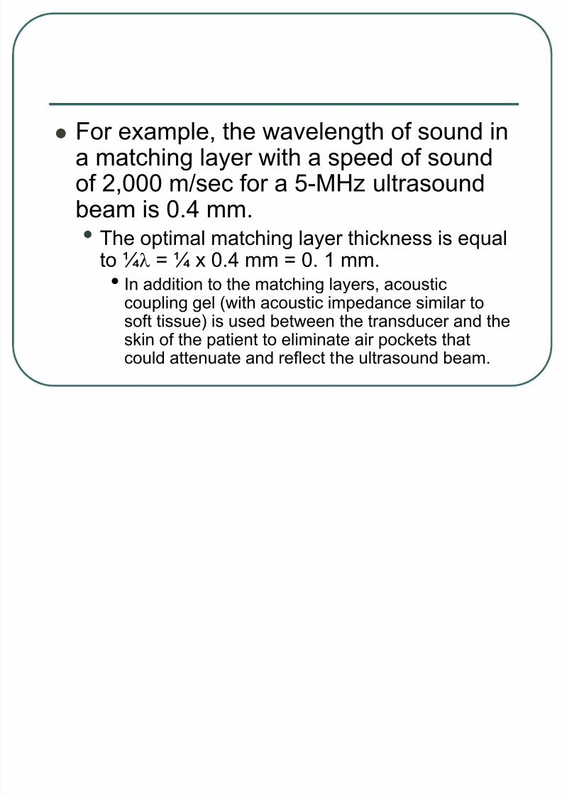
For example, the wavelength of sound ina matching layer with a speed of soundof 2,000 m/sec for a 5-MHz ultrasoundbeam is 0.4 mm.• The optimal matching layer thickness is equal
to ¼ = ¼ x 0.4 mm = 0. 1 mm.• In addition to the matching layers, acoustic
coupling gel (with acoustic impedance similar tosoft tissue) is used between the transducer and theskin of the patient to eliminate air pockets thatcould attenuate and reflect the ultrasound beam.
8/22/2019 Lecture Ultrasound Beams
http://slidepdf.com/reader/full/lecture-ultrasound-beams 35/126
Nonresonance (Broad-Bandwidth)
“Multifrequency” Transducers
Modern transducer design coupled with digital
signal processing enables “multifrequency or
“multihertz” transducer operation, whereby rhe
center frequency can be adjusted in he
transmit mode.
• Unlike the resonance transducer design, the
piezoelectric element is intricately machined into a
large number of small “rods,” and then filled with anepoxy resin to create a smooth surface.

8/22/2019 Lecture Ultrasound Beams
http://slidepdf.com/reader/full/lecture-ultrasound-beams 36/126

8/22/2019 Lecture Ultrasound Beams
http://slidepdf.com/reader/full/lecture-ultrasound-beams 37/126

8/22/2019 Lecture Ultrasound Beams
http://slidepdf.com/reader/full/lecture-ultrasound-beams 38/126
The acoustic properties are closer to
issue than a pure PZT material, and thus
provide a greater transmission efficiencyof the ultrasound beam without resorting
to multiple matching layers.
• Multifrequency transducers have bandwidths
that exceed 80% of the center frequency.
8/22/2019 Lecture Ultrasound Beams
http://slidepdf.com/reader/full/lecture-ultrasound-beams 39/126
Excitation of the multifrequencytransducer is accomplished with a short
square wave burst of 150 V with one tothree cycles, unlike the voltage spikeused for resonance transducers.
• This allows the center frequency to be
selected within the limits of the transducer bandwidth.

8/22/2019 Lecture Ultrasound Beams
http://slidepdf.com/reader/full/lecture-ultrasound-beams 40/126
Likewise, the broad bandwidth responsepermits the reception of echoes within a
wide range of frequencies.• For instance, ultrasound pulses can beproduced at a low frequency, and the echoesreceived at higher frequency.

8/22/2019 Lecture Ultrasound Beams
http://slidepdf.com/reader/full/lecture-ultrasound-beams 41/126
“Harmonic imaging” is a recentlyintroduced technique that uses this
ability;• lower frequency ultrasound is transmitted intothe patient, and the higher frequencyharmonics (e.g., two times the transmittedcenter frequency) created from the interactionwith contrast agents and tissues, are receivedas echoes.

8/22/2019 Lecture Ultrasound Beams
http://slidepdf.com/reader/full/lecture-ultrasound-beams 42/126
Native tissue harmonic imaging has
certain advantages including greater
depth of penetration, noise and clutter removal, and improved lateral spatial
resolution.

8/22/2019 Lecture Ultrasound Beams
http://slidepdf.com/reader/full/lecture-ultrasound-beams 43/126
Transducer Arrays
The majority of ultrasound systems
employ transducers with many individual
rectangular piezoelectric elementsarranged in linear or curvilinear arrays.
• Typically, 128 to 512 individual rectangular
elements compose the transducer assembly.
• Each element has a width typically less than half the wavelength and a length of several millimeters.

8/22/2019 Lecture Ultrasound Beams
http://slidepdf.com/reader/full/lecture-ultrasound-beams 44/126
Two modes of
activation are used
to produce a beam.
• These are the “linear”(sequential) and
“phased”
activation/receive
modes.

8/22/2019 Lecture Ultrasound Beams
http://slidepdf.com/reader/full/lecture-ultrasound-beams 45/126
Linear Arrays
Linear array transducers typically contain
256 to 512 elements; physically these
are the largest transducer assemblies.

8/22/2019 Lecture Ultrasound Beams
http://slidepdf.com/reader/full/lecture-ultrasound-beams 46/126
In operation, the simultaneous firing of’ a
small group of 20 adjacent elements
produces the ultrasound beam.• The simultaneous activation produces a
synthetic aperture (effetive transducer width)
defined by the number of active elements.

8/22/2019 Lecture Ultrasound Beams
http://slidepdf.com/reader/full/lecture-ultrasound-beams 47/126
Echoes are detected in the receive mode
by acquiring signals from most of the
transducer elements.• Subsequent “A-line” acquisition occurs by
firing another group of transducer elements
displaced by one or two elements.
8/22/2019 Lecture Ultrasound Beams
http://slidepdf.com/reader/full/lecture-ultrasound-beams 48/126
A rectangular field of view is produced
with this transducer arrangement.
• For a curvilinear array, a trapezoidal field of view is produced.
8/22/2019 Lecture Ultrasound Beams
http://slidepdf.com/reader/full/lecture-ultrasound-beams 49/126
Phased Arrays
A phased-array transducer is usually
composed of 64 to 128 individual
elements in a smaller package than alinear array transducer.
• All transducer elements are activated nearly
(but not exactly) simultaneously to produce a
single ultrasound beam.

8/22/2019 Lecture Ultrasound Beams
http://slidepdf.com/reader/full/lecture-ultrasound-beams 50/126
By using time delays in the electrical activarion
of the discrete elements across the face of the
transducer, the ultrasound beam can be
steered and focused electronically withoutmoving the transducer.
• During ultrasound signal reception, all of the
transducer elements detect the returning echoes from
the beam path, and sophisticated algorithmssynthesize the image from the detected data.
8/22/2019 Lecture Ultrasound Beams
http://slidepdf.com/reader/full/lecture-ultrasound-beams 51/126
BEAM PROPERTIES
The ultrasound beam propagates as alongitudinal wave from the transducer surface into the propagation medium,and exhibits two distinct beam patterns:• a slightly converging beam out to a distance
specified by the geometry and frequency of the transducer (the near field), and
• a diverging beam beyond that point (the far field).

8/22/2019 Lecture Ultrasound Beams
http://slidepdf.com/reader/full/lecture-ultrasound-beams 52/126
For an unfocused,
single-element
transducer, the
length of the near
field is determined
by the transducer
diameter and thefrequency of the
transmitted sound.

8/22/2019 Lecture Ultrasound Beams
http://slidepdf.com/reader/full/lecture-ultrasound-beams 53/126
For multiple transducer element arrays,an “effective” transducer diameter isdetermined by the excitation of a group
of’ transducer elements.• Because of the interactions of each of the
individual beams and the ability to focus and steer the overall beam, the formulasfor a single-element, unfocused transducer are not directly applicable.

8/22/2019 Lecture Ultrasound Beams
http://slidepdf.com/reader/full/lecture-ultrasound-beams 54/126
The Near Field
The near field, also known as theFresnel zone, is adjacent to thetransducer face and has a converging
beam profile.• Beam convergence in the near field occurs
because of multiple constructive anddestructive interference patterns of the
ultrasound waves from the transducer surface.

8/22/2019 Lecture Ultrasound Beams
http://slidepdf.com/reader/full/lecture-ultrasound-beams 55/126
Huygen’s principle describes a large
transducer surface as an infinite
number of point sources of soundenergy where each point is
characterized as a radial emitter.
• By analogy, a pebble dropped in a quiet pond
creates a radial wave pattern.
8/22/2019 Lecture Ultrasound Beams
http://slidepdf.com/reader/full/lecture-ultrasound-beams 56/126
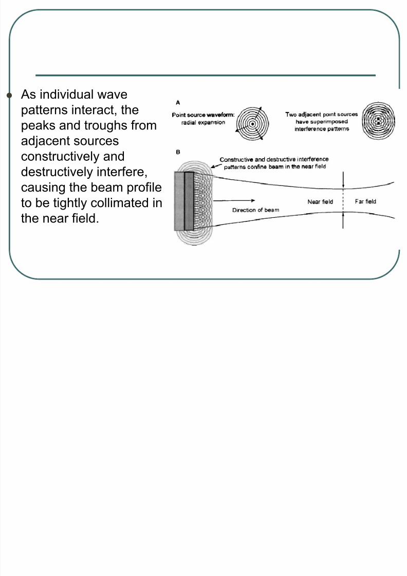
As individual wave
patterns interact, the
peaks and troughs from
adjacent sourcesconstructively and
destructively interfere,
causing the beam profile
to be tightly collimated in
the near field.

8/22/2019 Lecture Ultrasound Beams
http://slidepdf.com/reader/full/lecture-ultrasound-beams 57/126
The ultrasound beam path is thus largely
confined to the dimensions of the active
portion of the transducer surface, withthe beam diameter converging to
approximately half the transducer
diameter at the end of the near field.

8/22/2019 Lecture Ultrasound Beams
http://slidepdf.com/reader/full/lecture-ultrasound-beams 58/126
The near field length is dependent on the
transducer frequency and diameter:
• where d is the transducer diameter, r is the
transducer radius, and is the wavelength of
ultrasound in the propagation medium.
22
4
r d length field Near

8/22/2019 Lecture Ultrasound Beams
http://slidepdf.com/reader/full/lecture-ultrasound-beams 59/126
In soft tissue, = 1.54mm/f(MHz), and
the near field length can be expressed
as a function of frequency:
mm
MHz mmd length field Near
22
54.14

8/22/2019 Lecture Ultrasound Beams
http://slidepdf.com/reader/full/lecture-ultrasound-beams 60/126
A higher transducer
frequency (shorter
wavelength) will
result in a longer near field, as will a
larger diameter
element.
8/22/2019 Lecture Ultrasound Beams
http://slidepdf.com/reader/full/lecture-ultrasound-beams 61/126
For a 10-mm-diameter transducer, the
near field extends 5.7 cm at 3.5 MHz
and 16.2 cm at 10 MHz in soft tissue.• For a 15-mm-diameter transducer, the
corresponding near field lengths are 12.8 and
36.4 cm, respectively.

8/22/2019 Lecture Ultrasound Beams
http://slidepdf.com/reader/full/lecture-ultrasound-beams 62/126
Lateral resolution (the ability of the
system to resolve objects in a direction
perpendicular to the beam direction) isdependent on the beam diameter and is
best at the end of the near field for a
single-element transducer.
• Lateral resolution is worst in areas close to
and far from the transducer surface.

8/22/2019 Lecture Ultrasound Beams
http://slidepdf.com/reader/full/lecture-ultrasound-beams 63/126
Pressure amplitude characteristics in thenear field are very complex, caused bythe constructive and destructive
interference wave patterns of theultrasound beam.• Peak ultrasound pressure occurs at the end of
the near field, corresponding to the minimumbeam diameter for a single-elementtransducer.

8/22/2019 Lecture Ultrasound Beams
http://slidepdf.com/reader/full/lecture-ultrasound-beams 64/126
Pressures vary rapidly from peak
compression to peak rarefaction several
times during transit through the near field.
• Only when the far field is reached do the
ultrasound pressure variations decrease
continuously.
8/22/2019 Lecture Ultrasound Beams
http://slidepdf.com/reader/full/lecture-ultrasound-beams 65/126
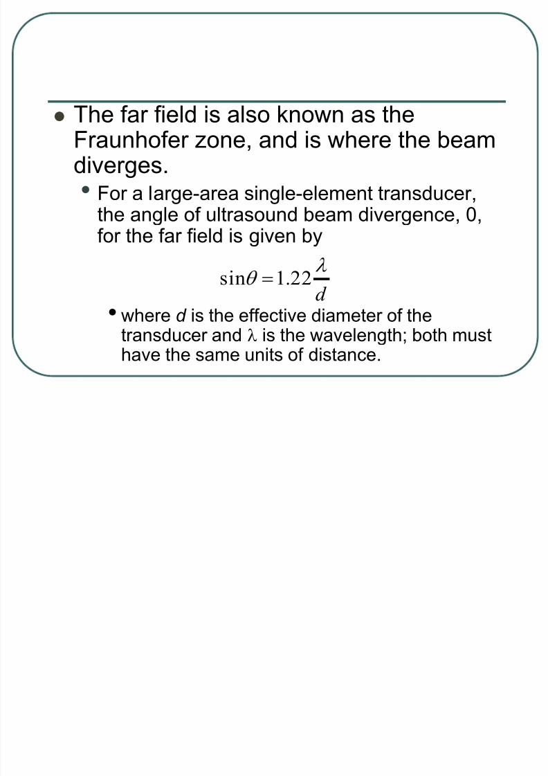
The far field is also known as theFraunhofer zone, and is where the beamdiverges.
• For a large-area single-element transducer,the angle of ultrasound beam divergence, 0,for the far field is given by
• where d is the effective diameter of thetransducer and is the wavelength; both musthave the same units of distance.
d
22.1sin

8/22/2019 Lecture Ultrasound Beams
http://slidepdf.com/reader/full/lecture-ultrasound-beams 66/126
Less beam divergence occurs with high-
frequency, large-diameter transducers.
• Unlike the near field, where beam intensityvaries from maximum to minimum to
maximum in a converging beam, ultrasound
intensity in the far field decreases
monotonically with distance.

8/22/2019 Lecture Ultrasound Beams
http://slidepdf.com/reader/full/lecture-ultrasound-beams 67/126
Focused Transducers
Single-element transducers are focused
by using a curved piezoelectric element
or a curved acoustic lens to reduce thebeam profile.
• The focal distance, the length from the
transducer to the narrowest beam width, is
shorter than the focal length of a non-focusedtransducer and is fixed.

8/22/2019 Lecture Ultrasound Beams
http://slidepdf.com/reader/full/lecture-ultrasound-beams 68/126
The focal zone is defined as the region
over which the width of the beam is less
than two times the width at the focaldistance;
• Thus, the transducer frequency and
dimensions should be chosen to match the
depth requirements of the clinical situation.

8/22/2019 Lecture Ultrasound Beams
http://slidepdf.com/reader/full/lecture-ultrasound-beams 69/126
Transducer Array Beam
Formation and Focusing
In a transducer array, the narrowpiezoelectric element width (typicallyless than one wavelength) produces a
diverging beam at a distance very closeto the transducer face.• Formation and convergence of the ultrasound
beam occurs with the operation of several or
all of the transducer elements at the sametime.
8/22/2019 Lecture Ultrasound Beams
http://slidepdf.com/reader/full/lecture-ultrasound-beams 70/126
Transducer elements in a linear array that are
fired simultaneously produce an effective
transducer width equal to the sum of the widths
of the individual elements.• Individual beams interact via constructive and
destructive interference to produce a collimated
beam that has properties similar to the properties
of a single transducer of the same size.

8/22/2019 Lecture Ultrasound Beams
http://slidepdf.com/reader/full/lecture-ultrasound-beams 71/126
With a phased-array transducer, thebeam is formed by interaction of theindividual wave fronts from each
transducer, each with a slight differencein excitation time.• Minor phase differences of adjacent beams
form constructive and destructive wave
summations that steer or focus the beamprofile.

8/22/2019 Lecture Ultrasound Beams
http://slidepdf.com/reader/full/lecture-ultrasound-beams 72/126
Transmit Focus
For a single transducer or group of simultaneously fired elements in a linear array,
• The focal distance is a function of thetransducer diameter (or the width of the groupof simultaneously fired elements),
• The center operating frequency, and
• The presence of any acoustic lenses attachedto the element surface.

8/22/2019 Lecture Ultrasound Beams
http://slidepdf.com/reader/full/lecture-ultrasound-beams 73/126
Phased array transducers and many
linear array transducers allow a
selectable focal distance by applyingspecific timing delays between
transducer elements that cause the
beam to converge at a specified
distance.
8/22/2019 Lecture Ultrasound Beams
http://slidepdf.com/reader/full/lecture-ultrasound-beams 74/126
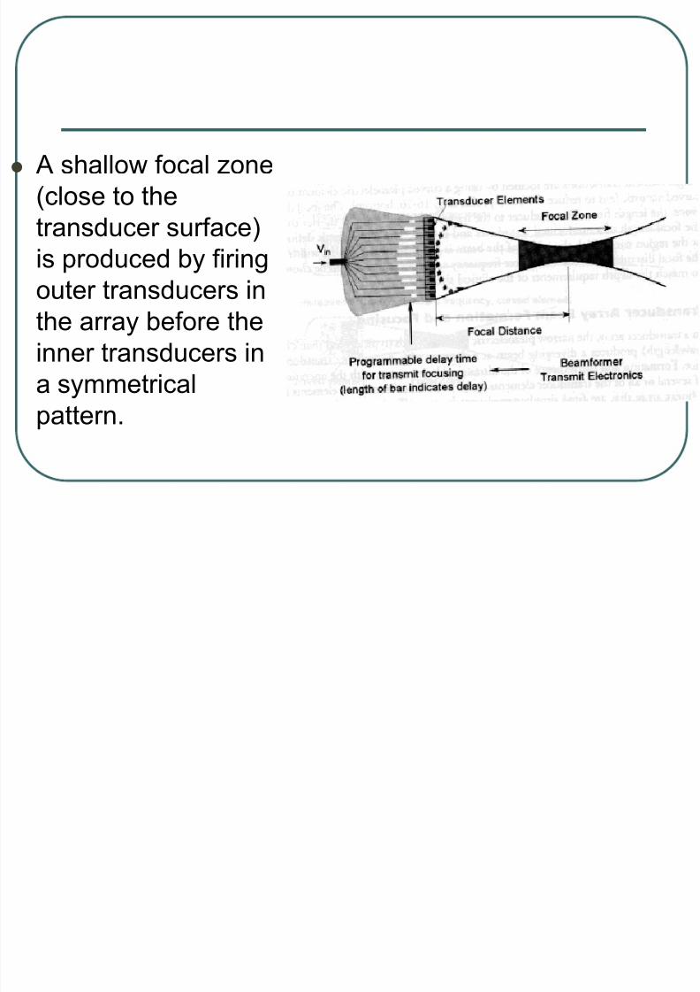
A shallow focal zone
(close to the
transducer surface)
is produced by firingouter transducers in
the array before the
inner transducers in
a symmetricalpattern.

8/22/2019 Lecture Ultrasound Beams
http://slidepdf.com/reader/full/lecture-ultrasound-beams 75/126
Greater focal distances are achieved byreducing the delay time differencesamong the transducer elements,
resulting in more distal beamconvergence.• Multiple transmit focal zones are created by
repeatedly acquiring data over the same
volume, but with different phase timing of thetransducer array elements.

8/22/2019 Lecture Ultrasound Beams
http://slidepdf.com/reader/full/lecture-ultrasound-beams 76/126
Receive Focus
In a phased array transducer, theechoes received by all of the individualtransducer elements are summed
together to create the ultrasound signalfrom a given depth.• Echoes received at the edge of the element
array travel a slightly longer distance than
those received at the center of the array,particularly at shallow depths.
8/22/2019 Lecture Ultrasound Beams
http://slidepdf.com/reader/full/lecture-ultrasound-beams 77/126
Signals from individual transducer elements therefore must be rephased toavoid a loss of resolution when the
individual signals are synthesized into animage.• Dynamic receive focusing is a method to
rephase the signals by dynamically
introducing electronic delays as a function of depth (time).

8/22/2019 Lecture Ultrasound Beams
http://slidepdf.com/reader/full/lecture-ultrasound-beams 78/126
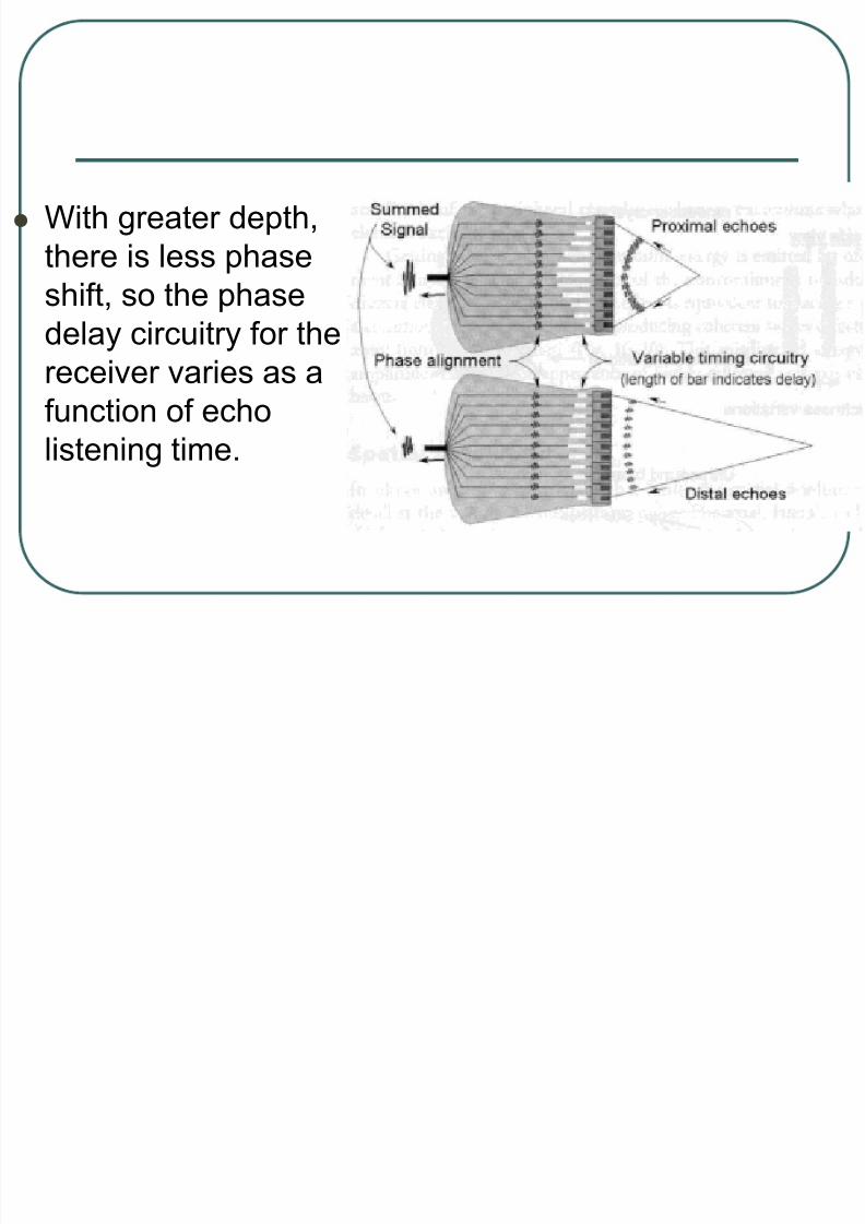
At shallow depths, rephasing delays
between adjacent transducer elements
are greatest.
8/22/2019 Lecture Ultrasound Beams
http://slidepdf.com/reader/full/lecture-ultrasound-beams 79/126
With greater depth,
there is less phase
shift, so the phase
delay circuitry for the
receiver varies as a
function of echo
listening time.

8/22/2019 Lecture Ultrasound Beams
http://slidepdf.com/reader/full/lecture-ultrasound-beams 80/126
In addition to phased array transducers,
many linear array transducers permit
dynamic receive focusing among the
active element group.
8/22/2019 Lecture Ultrasound Beams
http://slidepdf.com/reader/full/lecture-ultrasound-beams 81/126
Dynamic Aperture
The lateral spatial resolution of the linear array beam varies with depth, dependenton the total width of the simultaneously
fired elements (aperture).• A process termed dynamic aperture increases
the number of active receiving elements in thearray with reflector depth so that the lateral
resolution does not degrade with depth of propagation.

8/22/2019 Lecture Ultrasound Beams
http://slidepdf.com/reader/full/lecture-ultrasound-beams 82/126
Side Lobes and Grating
Lobes
8/22/2019 Lecture Ultrasound Beams
http://slidepdf.com/reader/full/lecture-ultrasound-beams 83/126
Side lobes are unwanted emissions of
ultrasound energy directed away from the main
pulse, caused by the radial expansion and
contraction of the transducer element duringthickness contraction and expansion.
• In the receive mode of transducer operation,
echoes generated from the side lobes are
unavoidably remapped along the main beam,which can introduce artifacts in the image.
8/22/2019 Lecture Ultrasound Beams
http://slidepdf.com/reader/full/lecture-ultrasound-beams 84/126
In continuous mode operation, thenarrow frequency bandwidth of thetransducer (high Q) causes the side lobe
energy to be a significant fraction of thetotal beam.• In pulsed mode operation. the low Q
broadband ultrasound beam produces a
spectrum of acoustic wavelengths chatreduces the emission of side lobe energy.

8/22/2019 Lecture Ultrasound Beams
http://slidepdf.com/reader/full/lecture-ultrasound-beams 85/126
For multielement
arrays, side lobe
emission occurs in a
forward directionalong the main
beam.

8/22/2019 Lecture Ultrasound Beams
http://slidepdf.com/reader/full/lecture-ultrasound-beams 86/126
By keeping the individual transducer element widths small (less than half thewavelength) the side lobe emissions are
reduced.• Another method to minimize side lobes with
array transducers is to reduce the amplitudeof the peripheral transducer element
excitations relative to the central elementexcitations.

8/22/2019 Lecture Ultrasound Beams
http://slidepdf.com/reader/full/lecture-ultrasound-beams 87/126
Grating lobes result when ultrasound energy is
emitted far off-axis by multielement arrays, and
are a consequence of the noncontinuous
transducer surface of the discrete elements.• The grating lobe effect is equivalent to placing a
grating in front of a continuous transducer
element, producing coherent waves directed at a
large angle away from the main beam.

8/22/2019 Lecture Ultrasound Beams
http://slidepdf.com/reader/full/lecture-ultrasound-beams 88/126
This misdirected energy of relatively low
amplitude results in the appearance of
highly reflective, off-axis objects in the
main beam.

8/22/2019 Lecture Ultrasound Beams
http://slidepdf.com/reader/full/lecture-ultrasound-beams 89/126
Spatial Resolution

8/22/2019 Lecture Ultrasound Beams
http://slidepdf.com/reader/full/lecture-ultrasound-beams 90/126
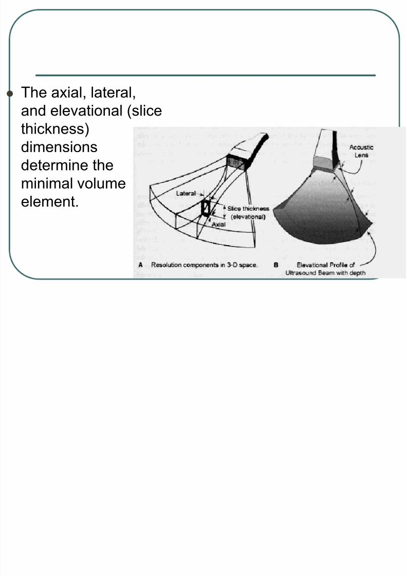
In ultrasound, the major factor that limits
the spatial resolution and visibility of
detail is the volume of the acoustic
pulse.
8/22/2019 Lecture Ultrasound Beams
http://slidepdf.com/reader/full/lecture-ultrasound-beams 91/126
The axial, lateral,
and elevational (slice
thickness)
dimensionsdetermine the
minimal volume
element.

8/22/2019 Lecture Ultrasound Beams
http://slidepdf.com/reader/full/lecture-ultrasound-beams 92/126
Each dimension has an effect on the
resolvability of objects in the image.

8/22/2019 Lecture Ultrasound Beams
http://slidepdf.com/reader/full/lecture-ultrasound-beams 93/126
Axial Resolution
Axial resolution (also known as linear,
range, longitudinal, or depth resolution)
refers to the ability to discern two closely
spaced objects in the direction of the
beam.
• Achieving good axial resolution requires that
the returning echoes be distinct withoutoverlap.

8/22/2019 Lecture Ultrasound Beams
http://slidepdf.com/reader/full/lecture-ultrasound-beams 94/126
The minimal required separation
distance between two reflectors is one-
half of the spatial pulse length (SPL) to
avoid the overlap of returning echoes, as
the distance traveled between two
reflectors is twice the separation
distance.

8/22/2019 Lecture Ultrasound Beams
http://slidepdf.com/reader/full/lecture-ultrasound-beams 95/126
Objects spaced
closer than ½ SPL
will not be resolved.

8/22/2019 Lecture Ultrasound Beams
http://slidepdf.com/reader/full/lecture-ultrasound-beams 96/126
The SPL is the number of cycles emitted
per pulse by the transducer multiplied by
the wavelength.
• Shorter pulses, producing better axial
resolution, can be achieved with greater
damping of the transducer element (to reduce
the pulse duration and number of cycles) or with higher frequency (to reduce wavelength).
8/22/2019 Lecture Ultrasound Beams
http://slidepdf.com/reader/full/lecture-ultrasound-beams 97/126
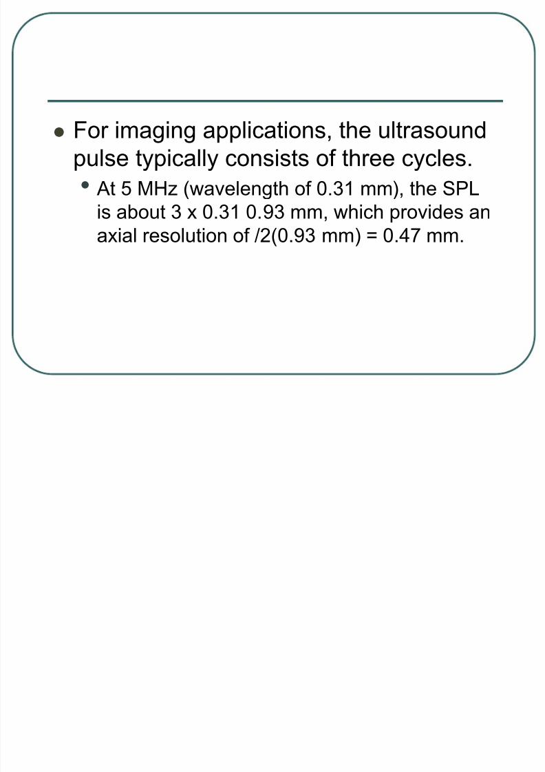
For imaging applications, the ultrasound
pulse typically consists of three cycles.
• At 5 MHz (wavelength of 0.31 mm), the SPL
is about 3 x 0.31 0.93 mm, which provides an
axial resolution of /2(0.93 mm) = 0.47 mm.

8/22/2019 Lecture Ultrasound Beams
http://slidepdf.com/reader/full/lecture-ultrasound-beams 98/126
At a given frequency, shorter pulse
lengths require heavy damping and low
Q, broad-bandwidth operation.
• For a constant damping factor, higher
frequencies (shorter wavelengths) give better
axial resolution, but the imaging depth is
reduced.• Axial resolution remains constant with depth.

8/22/2019 Lecture Ultrasound Beams
http://slidepdf.com/reader/full/lecture-ultrasound-beams 99/126
Lateral Resolution
Lateral resolution, also known as
azimuthal resolution, refers to the ability
to discern as separate two closely
spaced objects perpendicular to the
beam direction.
8/22/2019 Lecture Ultrasound Beams
http://slidepdf.com/reader/full/lecture-ultrasound-beams 100/126
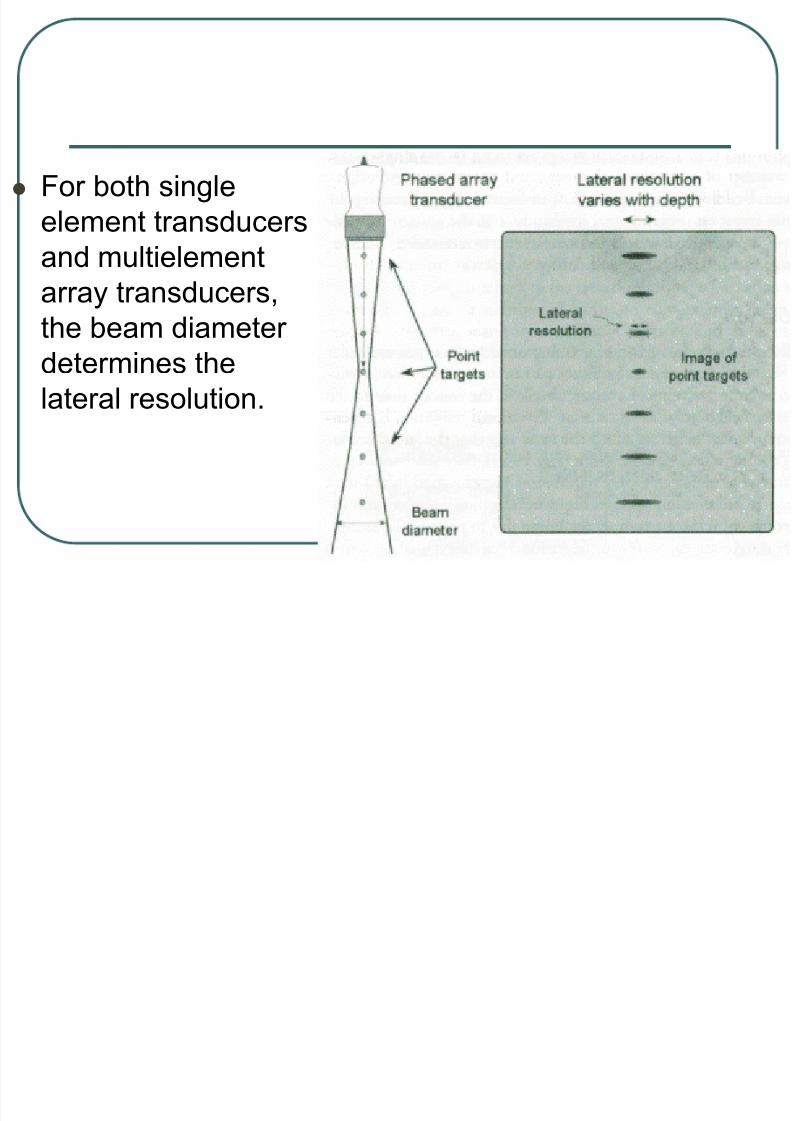
For both single
element transducers
and multielement
array transducers,the beam diameter
determines the
lateral resolution.

8/22/2019 Lecture Ultrasound Beams
http://slidepdf.com/reader/full/lecture-ultrasound-beams 101/126
Since the beam diameter varies with the
distance from the transducer in the near
and far field, the lateral resolution is
depth dependent.
• The best lateral resolution occurs at the near
field—far field face.

8/22/2019 Lecture Ultrasound Beams
http://slidepdf.com/reader/full/lecture-ultrasound-beams 102/126
At this depth, the effective beam
diameter is approximately equal to half
the transducer diameter.
• In the far field, the beam diverges and
substantially reduces the lateral resolution.

8/22/2019 Lecture Ultrasound Beams
http://slidepdf.com/reader/full/lecture-ultrasound-beams 103/126
The typical lateral resolution for an
unfocused transducer is approximately 2
to 5 mm.
• A focused transducer uses an acoustic lens (a
curved acoustic material analogous to an
optical lens) to decrease the beam diameter
at a specified distance from the transducer.

8/22/2019 Lecture Ultrasound Beams
http://slidepdf.com/reader/full/lecture-ultrasound-beams 104/126
With an acoustic lens, lateral resolution
at the near field-far field interface is
traded for better lateral resolution at a
shorter depth, but the far field beam
divergence is substantially increased.
• The lateral resolution of linear and curvilinear
array transducers can be varied.

8/22/2019 Lecture Ultrasound Beams
http://slidepdf.com/reader/full/lecture-ultrasound-beams 105/126
The number of elements simultaneously
activated in a group defines an
“effective” transducer width that has
similar behavior to a single transducer
element of the same width.
• Transmit and receive focusing can produce
focal at varying depths along each line.

8/22/2019 Lecture Ultrasound Beams
http://slidepdf.com/reader/full/lecture-ultrasound-beams 106/126
For the phased array transducer,
focusing to a specific depth is achieved
by both beam steering and
transmit/receive focusing to reduce the
effective beam width and improve lateral
resolution, especially in the near field.
8/22/2019 Lecture Ultrasound Beams
http://slidepdf.com/reader/full/lecture-ultrasound-beams 107/126
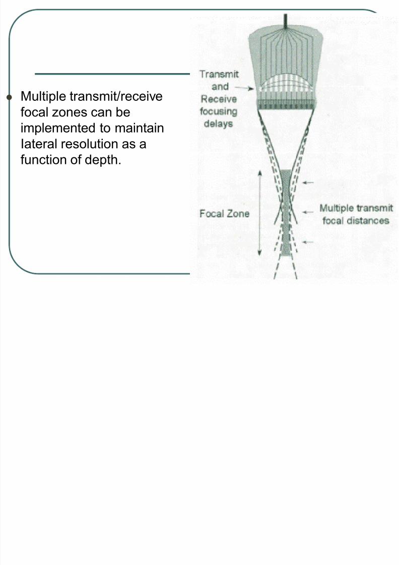
Multiple transmit/receive
focal zones can be
implemented to maintain
Iateral resolution as afunction of depth.

8/22/2019 Lecture Ultrasound Beams
http://slidepdf.com/reader/full/lecture-ultrasound-beams 108/126
Each focal zone requires separate pulse
echo sequences to acquire data.

8/22/2019 Lecture Ultrasound Beams
http://slidepdf.com/reader/full/lecture-ultrasound-beams 109/126
One way to accomplish this is to acquire dataalong one beam line multiple times (dependingon the number of transmit focal zones), and
accept only the echoes within each focal zone,building up a single line of in-focus zones.
• Increasing the number of focal zones improvesoverall lateral resolution, but the amount of timerequired to produce an image increases andreduces the frame rate and/or number of scanlines per image.

8/22/2019 Lecture Ultrasound Beams
http://slidepdf.com/reader/full/lecture-ultrasound-beams 110/126
Elevational Resolution
The elevational or slice-thickness
dimension of the ultrasound beam is
perpendicular to the image plane.
• Slice thickness plays a significant part in
image resolution, particularly with respect to
volume averaging of acoustic details in the
regions dose to the transducer and in the far
field beyond the focal zone.

8/22/2019 Lecture Ultrasound Beams
http://slidepdf.com/reader/full/lecture-ultrasound-beams 111/126
Elevationalresolution isdependent on the
transducer elementheight in much thesame way that thelateral resolution isdependent on thetransducer elementwidth.
8/22/2019 Lecture Ultrasound Beams
http://slidepdf.com/reader/full/lecture-ultrasound-beams 112/126
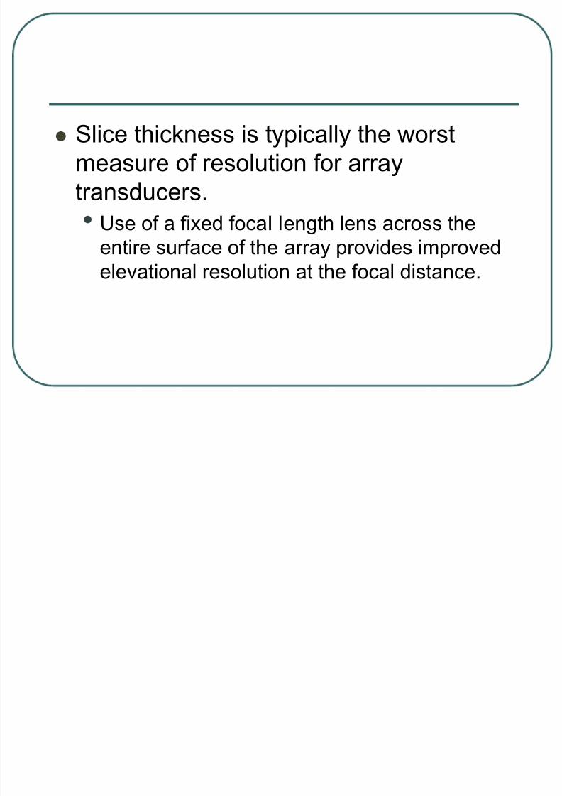
Slice thickness is typically the worst
measure of resolution for array
transducers.
• Use of a fixed focaI length lens across the
entire surface of the array provides improved
elevational resolution at the focal distance.
8/22/2019 Lecture Ultrasound Beams
http://slidepdf.com/reader/full/lecture-ultrasound-beams 113/126
Unfortunately, this compromises
resolution due to partial volume
averaging before and after the
elevational focal zone (elevational
resolution quality control phantom image
shows the effects of variable resolution
with depth.

8/22/2019 Lecture Ultrasound Beams
http://slidepdf.com/reader/full/lecture-ultrasound-beams 114/126
Multiple linear array transducers with fiveto seven rows, known as 1.5-dimensional (1.5-D) transducer arrays,
have the ability to steer and focus thebeam in the elevational dimension.

8/22/2019 Lecture Ultrasound Beams
http://slidepdf.com/reader/full/lecture-ultrasound-beams 115/126
Elevational focusing is implemented withphased excitation of the outer to inner arrays to minimize the slice thickness
dimension at a given depth (Fig. 16-25).

8/22/2019 Lecture Ultrasound Beams
http://slidepdf.com/reader/full/lecture-ultrasound-beams 116/126
By using subsequent excitations withdifferent focusing distances, multipletransmit focusing can produce smaller
slice thickness over a range of tissuedepths.
• A disadvantage of elevational focusing is aframe rate reduction penalty required for multiple excitations to build one image.

8/22/2019 Lecture Ultrasound Beams
http://slidepdf.com/reader/full/lecture-ultrasound-beams 117/126
The increased width of the transducer array also limits positioning flexibility.
• Extension to full 2D transducer arrays with
enhancements in computational power willallow 3D imaging with uniform resolutionthroughout the image volume.

8/22/2019 Lecture Ultrasound Beams
http://slidepdf.com/reader/full/lecture-ultrasound-beams 118/126
IMAGE DATA ACQUISITION
Understanding ultrasonic image
formation requires knowledge of
ultrasound production, propagation, and
interactions.
• Images are created using a pulse echo
method of ultrasound production and
detection.

8/22/2019 Lecture Ultrasound Beams
http://slidepdf.com/reader/full/lecture-ultrasound-beams 119/126
• Each pulse transmits directionally into the
patient, and then experiences partial
reflections from tissue interfaces that create
echoes, which return to the transducer.

8/22/2019 Lecture Ultrasound Beams
http://slidepdf.com/reader/full/lecture-ultrasound-beams 120/126
Image formation using
the pulse echo approach
requires a number of
hardware components:
• the beam former,
• pulser,
• receiver,
• amplifier,
• scan converter/imagememory, and
• display system.

8/22/2019 Lecture Ultrasound Beams
http://slidepdf.com/reader/full/lecture-ultrasound-beams 121/126
Ultrasound equipment is
rapidly evolving toward
digital electronics and
processing, and current
state-of-the-art systems
use various combin-
ations of analog and
digital electronics.
8/22/2019 Lecture Ultrasound Beams
http://slidepdf.com/reader/full/lecture-ultrasound-beams 122/126
Beam Formers
The beam former is responsible for generating
the electronic delays for individual transducer
elements in an array to achieve transmit and
receive focusing and, in phased arrays, beamsteering.
• Most modern, high-end ultrasound equipment
incorporates a digital beam former and digital
electronics for both transmit and receivefunctions.

8/22/2019 Lecture Ultrasound Beams
http://slidepdf.com/reader/full/lecture-ultrasound-beams 123/126
A digital beam former controls application-
specific integrated circuits (ASICs) that
provide transmit/receive switches, digital-to-
analog and analog-to-digital converters, andpreamplification and time gain compensation
circuitry for each of the transducer elements
in the array.

8/22/2019 Lecture Ultrasound Beams
http://slidepdf.com/reader/full/lecture-ultrasound-beams 124/126
Major advantages of digital acquisition
and processing include the flexibility to
introduce new ultrasound capabilities by
programmable software algorithms and
to enhance control of the acoustic beam.

8/22/2019 Lecture Ultrasound Beams
http://slidepdf.com/reader/full/lecture-ultrasound-beams 125/126
Pulser
The pulser (also known as the transmitter)
provides the electrical voltage for exciting the
piezoelectric transducer elcnwnts, and controls
the output transmit power by adjustment of theapplied voltage.
• In digital beam-former systems, a digital-to analog-
converter determines the amplitude of the voltage. An
increase in transmit amplitude creates higher intensitysound and improves echo detection from weaker
reflectors.

8/22/2019 Lecture Ultrasound Beams
http://slidepdf.com/reader/full/lecture-ultrasound-beams 126/126
A direct consequence is higher signal-to-noiseratio in the images, but also higher power deposition to the patient. User controls of theoutput power are labeled “output,” “power,”
“dB,” or “transmit” by the manufacturer. Insome systems, a low power setting for obstetric imaging is available to reduce power deposition to the fetus. A method for indicatingoutput power in terms of a thermal index (TI)
and mechanical index (MI) is usually provided(see section 16.1 1).
![[PPT]Ultrasound Lecture 1 - Nc State Universityradfileshare.cvm.ncsu.edu/TP/VMA960/GenUS/GenUS.ppt · Web viewTitle Ultrasound Lecture 1 Author Tony Pease Last modified by Tony Pease](https://img.pdfslide.net/doc/110x75/5b00b05b7f8b9a84338cfc95/pptultrasound-lecture-1-nc-state-un-viewtitle-ultrasound-lecture-1-author-tony.jpg)


![Lecture 2 Beams Jb Apr 2013 [Compatibility Mode] (1)](https://img.pdfslide.net/doc/110x75/55cf9447550346f57ba0e153/lecture-2-beams-jb-apr-2013-compatibility-mode-1.jpg)


