Embed Size (px)
Citation preview
1
Rapidly Varied Channel Flow
Hydromechanics VVR090
Rapidly Varied Flow in Non-Prismatic Channels
Example of such flows to be discussed:
• bridge pier contractions
• control of hydraulic jumps
• drop spillway structures
• channel transitions
Rapidly varied flows previously discussed
• broad- and sharp-crested weirs
• critical flow flumes
Discussion focuses on practical aspects rather thantheoretical.
2
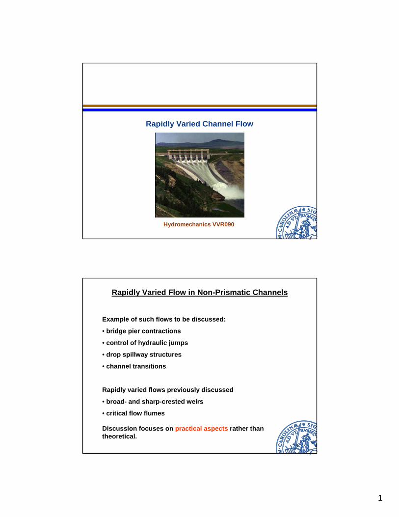
Bridge Piers
Bridge piers imply a constriction of the area. Backwater effects may occur => increased water level upstream with possible flooding.
Flow conditions at the pier:
• acceleration of the flow upstream
• continued acceleration and lowering of the water level at the constriction
• a vena contracta type section occurs in the constriction
• downstream the constriction uniform flow is re-established
Flow around the bridge pier might be analyzed using the momentum equation (takes into account the drag on the piers). However, an accurate solution typically requires experiments.
Formula developed by Yarnell (based on experiments):
( )( )2 2 43 3
3
2
1
5 0.6 15
1
y kFr k Fry
bb
Δ= + − σ+ σ
σ = −Γ
Γ =
3
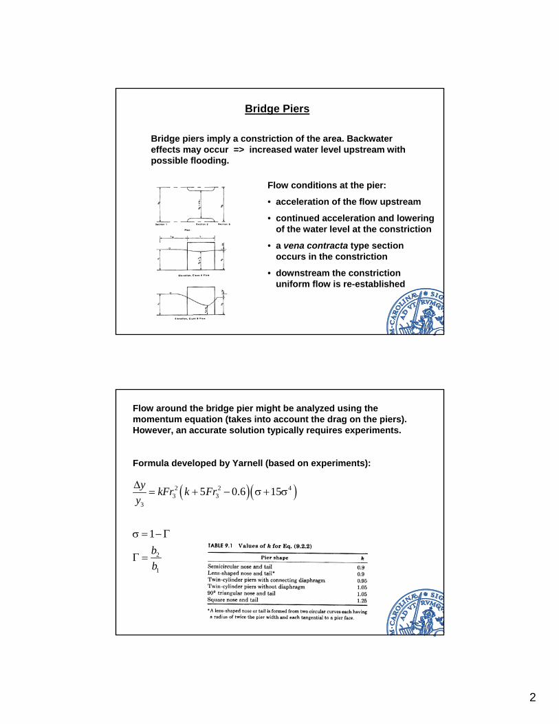
Yarnell formula only valid as long as the flow is not choked(i.e., no backwater effects).
Limiting value on G in order for choking not to take place maybe calculated from (E1 = E2 assumed):
( )
1/ 22
132
1
27
2L
Fr
Fr
⎛ ⎞⎜ ⎟Γ =⎜ ⎟+⎝ ⎠
If G < GL then choking occurs.
Derivation of Choking Conditions
The limit conditions corresponds to critical flow in the constriction and no backwater effects upstream.
Assume E1 = E2 and critical flow in section 2:
21
1 1 2
21
1 12
1
1
21
1
32 231
2 2
312 2
2 3
c
c
c
c
uE y y Eg
yugy y
yFryyFry
= + = =
+ =
+ =
+ =
4
Continuity equation:
1 1 1 2
1 1 1 2
11 2
1 1 1
3/ 2
1 1 21
c c
c c
c c
c
u y b u y b
u y b gy y b
y yu b bgy y y
yFrb by
=
=
=
⎛ ⎞= ⎜ ⎟⎝ ⎠
2 /3 2 /31 1
1 2 1/cy Fr Fr
y b b⎛ ⎞ ⎛ ⎞= =⎜ ⎟ ⎜ ⎟Γ⎝ ⎠⎝ ⎠
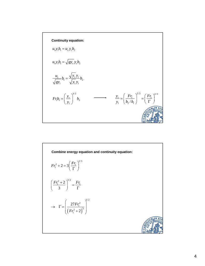
Combine energy equation and continuity equation:
( )
2/32 1
1
3/ 221 1
1/ 22
132
1
2 3
23
27
2
FrFr
Fr Fr
Fr
Fr
⎛ ⎞+ = ⎜ ⎟Γ⎝ ⎠
⎛ ⎞+=⎜ ⎟ Γ⎝ ⎠
⎛ ⎞⎜ ⎟→ Γ =⎜ ⎟+⎝ ⎠
5
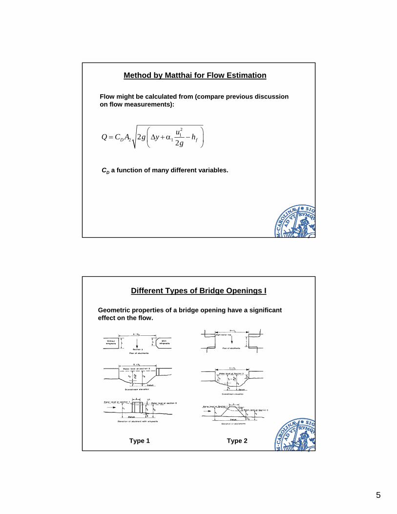
Method by Matthai for Flow Estimation
Flow might be calculated from (compare previous discussion on flow measurements):
21
2 122D fuQ C A g y hg
⎛ ⎞= Δ +α −⎜ ⎟
⎝ ⎠
CD a function of many different variables.
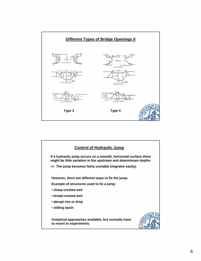
Different Types of Bridge Openings I
Geometric properties of a bridge opening have a significant effect on the flow.
Type 1 Type 2
6
Different Types of Bridge Openings II
Type 3 Type 4
Control of Hydraulic Jump
If a hydraulic jump occurs on a smooth, horizontal surface theremight be little variation in the upstream and downstream depths
=> The jump becomes fairly unstable (migrates easily).
However, there are different ways to fix the jump.
Example of structures used to fix a jump:
• sharp-crested weir
• broad-crested weir
• abrupt rise or drop
• stilling basin
Analytical approaches available, but normally have to resort to experiments.
7
Dimensional Analysis of Control Structure
The following relationship is obtained:
Dz: height of the sill
Fr1: Froude number in approaching flow
y1: depth of approaching flow
y2: depth of flow immediately upstream the sill
y3: depth of flow downstream
X: distance from toe of jump to the sill
31
1 2 1
, , yz XFry y y
⎛ ⎞Δ= Θ⎜ ⎟
⎝ ⎠
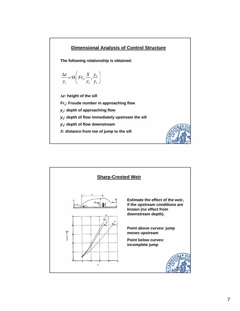
Sharp-Crested Weir
Estimate the effect of the weir, if the upstream conditions are known (no effect from downstream depth).
Point above curves: jump moves upstream
Point below curves: incomplete jump
8
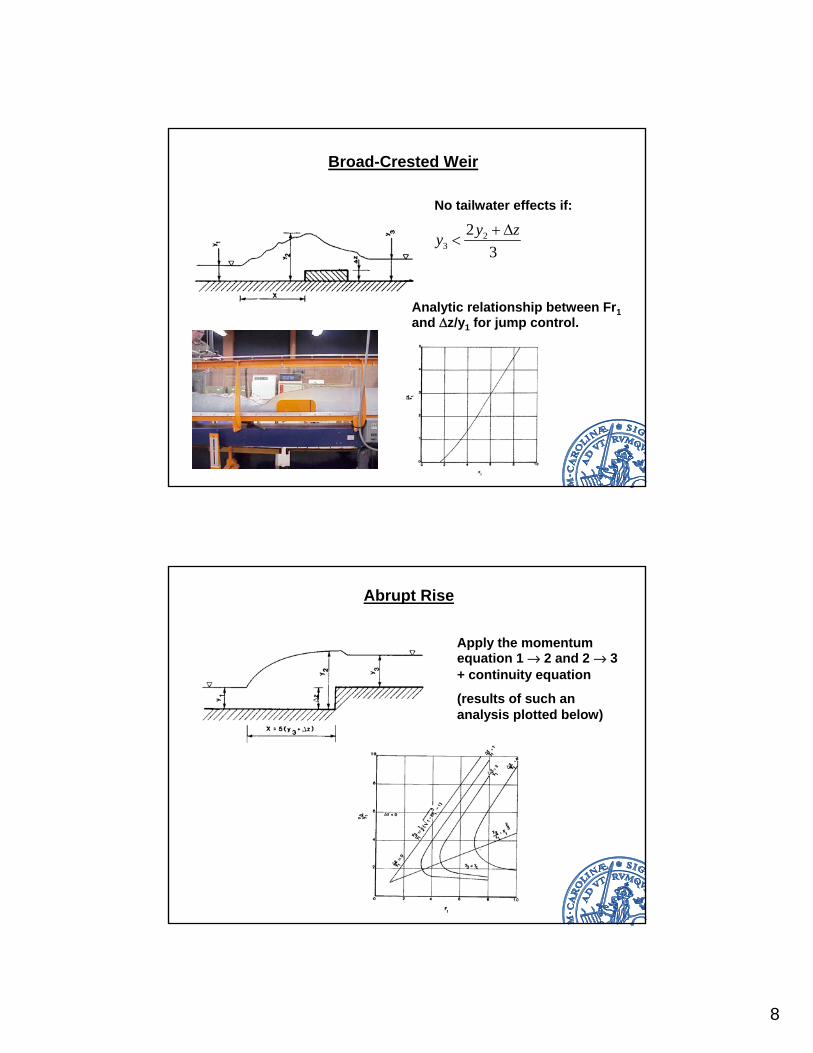
Broad-Crested Weir
No tailwater effects if:
23
23
y zy + Δ<
Analytic relationship between Fr1and Dz/y1 for jump control.
Abrupt Rise
Apply the momentum equation 1 Æ 2 and 2 Æ 3 + continuity equation
(results of such an analysis plotted below)
9
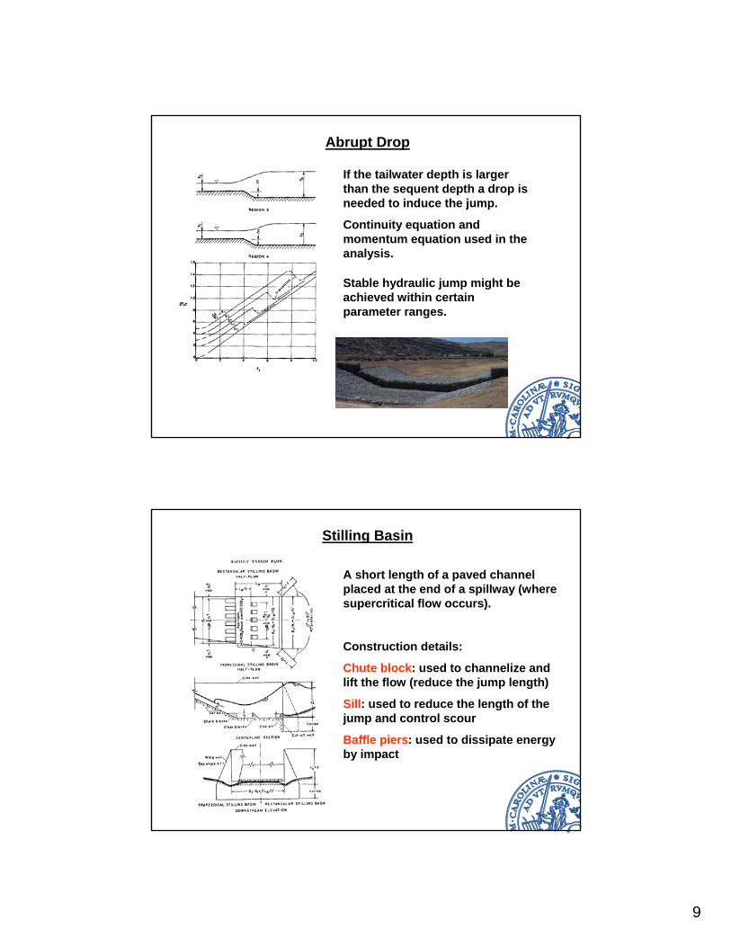
Abrupt Drop
If the tailwater depth is larger than the sequent depth a drop is needed to induce the jump.
Continuity equation and momentum equation used in the analysis.
Stable hydraulic jump might be achieved within certain parameter ranges.
Stilling Basin
A short length of a paved channel placed at the end of a spillway (where supercritical flow occurs).
Construction details:
Chute block: used to channelize and lift the flow (reduce the jump length)
Sill: used to reduce the length of the jump and control scour
Baffle piers: used to dissipate energy by impact
10
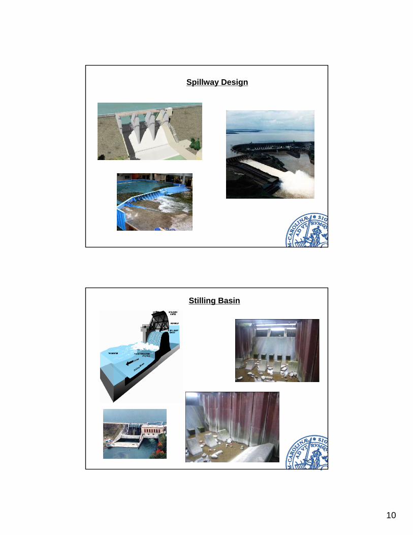
Spillway Design
Stilling Basin
11
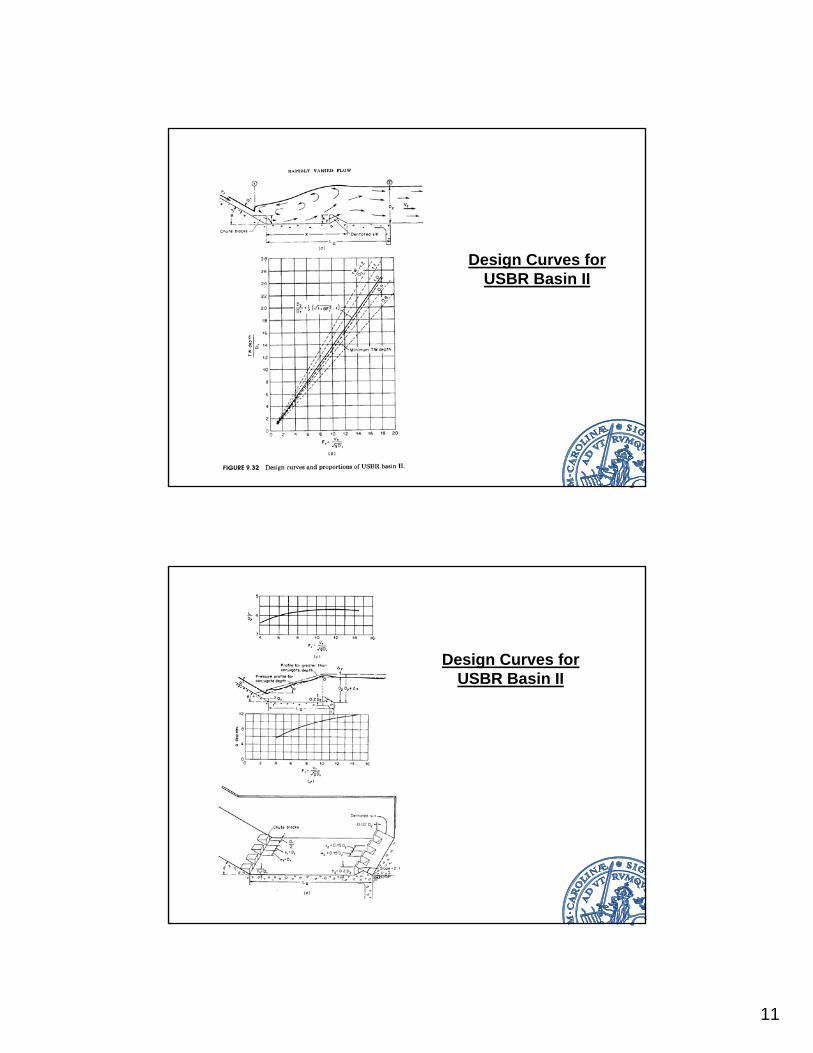
Design Curves for USBR Basin II
Design Curves for USBR Basin II
12
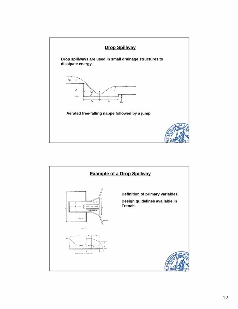
Drop Spillway
Drop spillways are used in small drainage structures to dissipate energy.
Aerated free-falling nappe followed by a jump.
Example of a Drop Spillway
Definition of primary variables.
Design guidelines available in French.
13
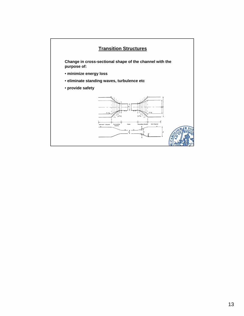
Transition Structures
Change in cross-sectional shape of the channel with the purpose of:
• minimize energy loss
• eliminate standing waves, turbulence etc
• provide safety