Embed Size (px)
Citation preview
Lecture7Development of Transmission Line Models
Professor Tom OverbyeDepartment of Electrical and
Computer Engineering
ECE 476
POWER SYSTEM ANALYSIS
2
Announcements
For next two lectures read Chapter 5. HW 2 is 4.10 (positive sequence is the same here as per phase),
4.18, 4.19, 4.23. Use Table A.4 values to determine the Geometric Mean Radius of the wires (i.e., the ninth column). Due September 15 in class.
“Energy Tour” opportunity on Oct 1 from 9am to 9pm. Visit a coal power plant, a coal mine, a wind farm and a bio-diesel processing plant. Sponsored by Students for Environmental Concerns. Cost isn’t finalized, but should be between $10 and $20. Contact Rebecca Marcotte at [email protected] for more information or to sign up.
3
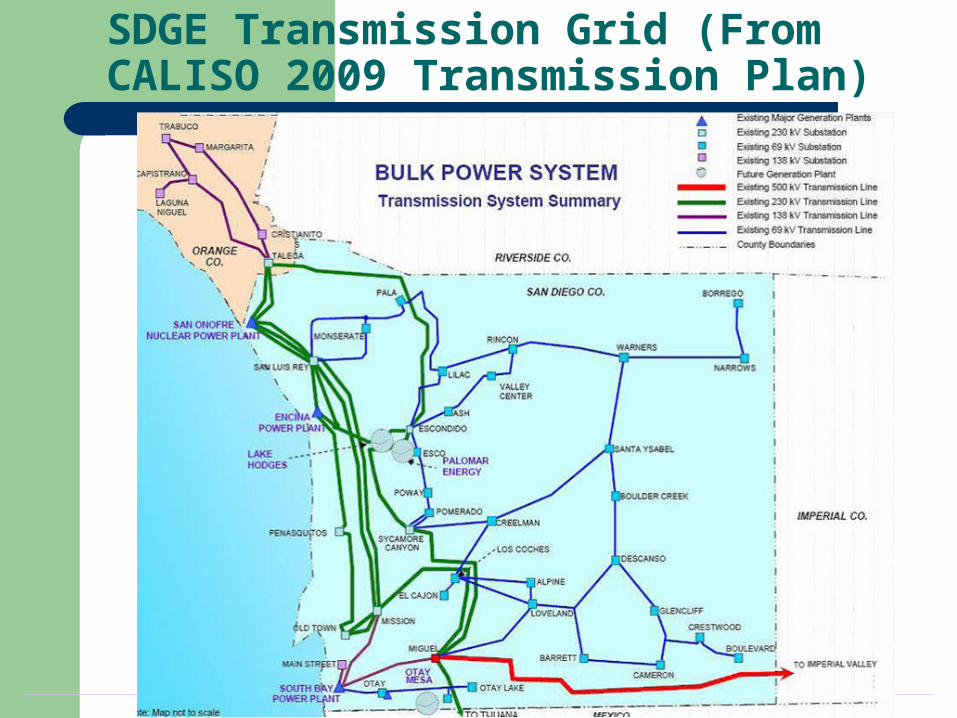
SDGE Transmission Grid (From CALISO 2009 Transmission Plan)
4
Line Conductors
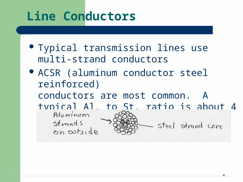
Typical transmission lines use multi-strand conductors
ACSR (aluminum conductor steel reinforced) conductors are most common. A typical Al. to St. ratio is about 4 to 1.
5
Line Conductors, cont’d
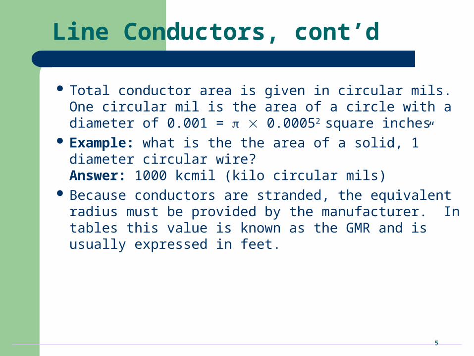
Total conductor area is given in circular mils. One circular mil is the area of a circle with a diameter of 0.001 = 0.00052 square inches
Example: what is the the area of a solid, 1” diameter circular wire? Answer: 1000 kcmil (kilo circular mils)
Because conductors are stranded, the equivalent radius must be provided by the manufacturer. In tables this value is known as the GMR and is usually expressed in feet.
6
Line Resistance
-8
-8
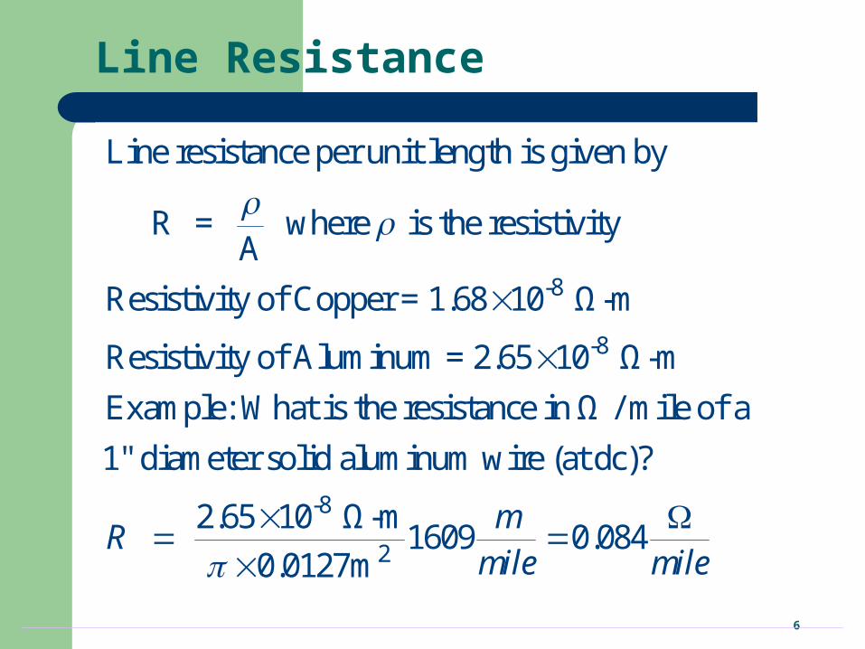
Line resistance per unit length is given by
R = where is the resistivityA
Resistivity of Copper = 1.68 10 Ω-m
Resistivity of Aluminum = 2.65 10 Ω-m
Example: What is the resistance in Ω / mile of a
-8
2
1" diameter solid aluminum wire (at dc)?
2.65 10 Ω-m1609 0.084
0.0127m
mR
mile mile
7
Line Resistance, cont’d
Because ac current tends to flow towards the surface of a conductor, the resistance of a line at 60 Hz is slightly higher than at dc.
Resistivity and hence line resistance increase as conductor temperature increases (changes is about 8% between 25C and 50C)
Because ACSR conductors are stranded, actual resistance, inductance and capacitance needs to be determined from tables.
8
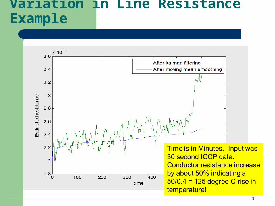
Variation in Line Resistance Example
9
Review of Electric Fields
eA
2
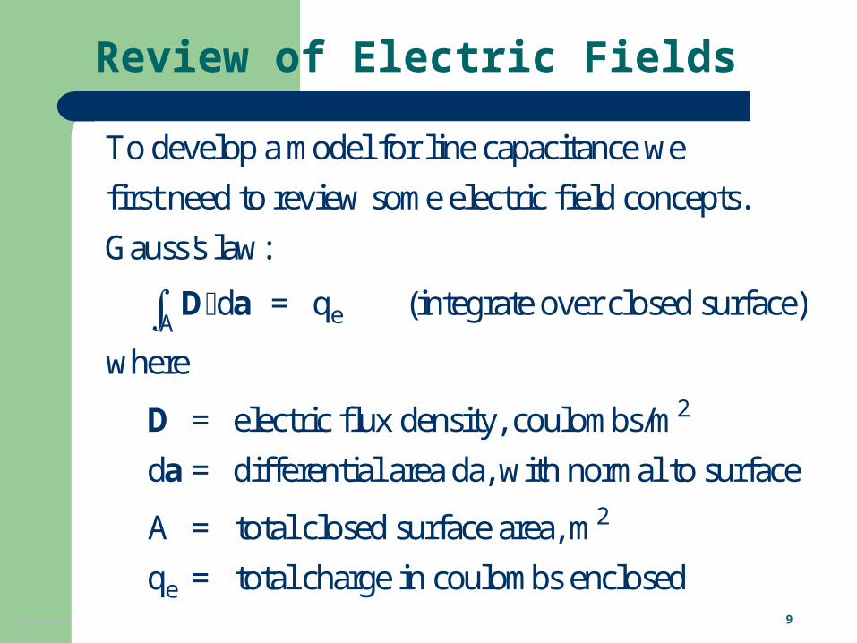
To develop a model for line capacitance we
first need to review some electric field concepts.
Gauss's law:
d = q (integrate over closed surface)
where
= electric flux density, coulombs/m
d = differential
D a
D
a
2
e
area da, with normal to surface
A = total closed surface area, m
q = total charge in coulombs enclosed
10
Gauss’s Law Example
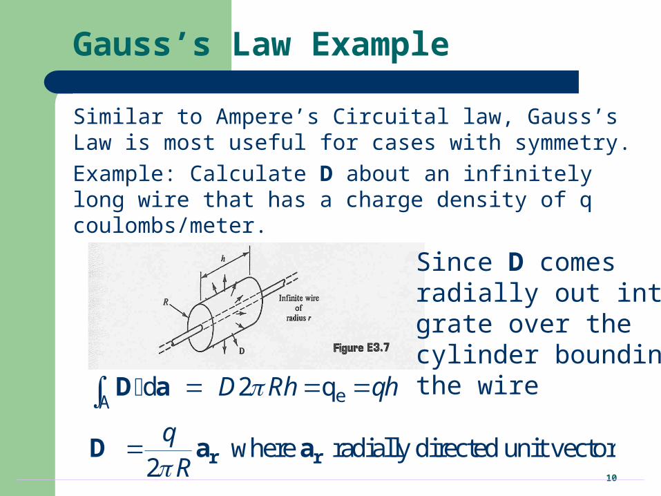
Similar to Ampere’s Circuital law, Gauss’s Law is most useful for cases with symmetry.
Example: Calculate D about an infinitely long wire that has a charge density of q coulombs/meter.
Since D comesradially out inte-grate over the cylinder bounding the wireeA
d 2 q
where radially directed unit vector2
D Rh qh
qR
r r
D a
D a a
11
Electric Fields
The electric field, E, is related to the electric flux density, D, by
D = E
where
E = electric field (volts/m)
= permittivity in farads/m (F/m)
= o r
o = permittivity of free space (8.85410-12 F/m)
r = relative permittivity or the dielectric constant(1 for dry air, 2 to 6 for most dielectrics)
12
Voltage Difference
P
P
The voltage difference between any two
points P and P is defined as an integral
V
In previous example the voltage difference between
points P and P , located radial distance R and R
f
d
E l
R
R
rom the wire is (assuming = )
V ln2 2
o
o o
Rq qdR
R R
13
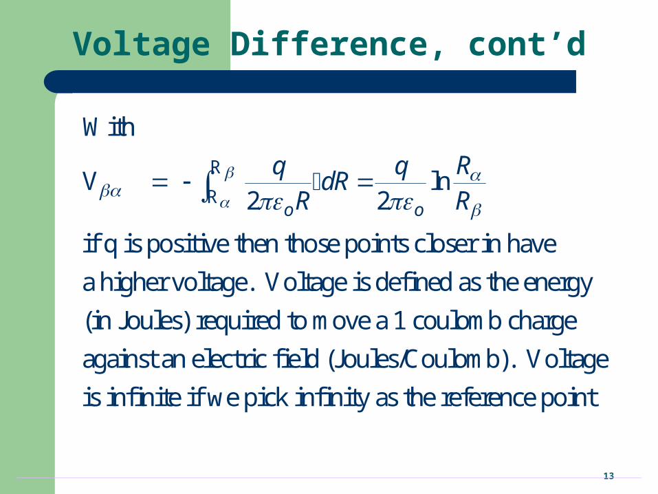
Voltage Difference, cont’d
R
R
With
V ln2 2
if q is positive then those points closer in have
a higher voltage. Voltage is defined as the energy
(in Joules) required to move a 1 coulomb charge
against an ele
o o
Rq qdR
R R
ctric field (Joules/Coulomb). Voltage
is infinite if we pick infinity as the reference point
14
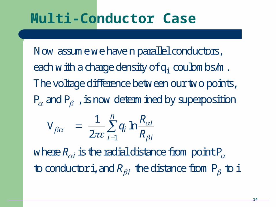
Multi-Conductor Case
i
1
Now assume we have n parallel conductors,
each with a charge density of q coulombs/m.
The voltage difference between our two points,
P and P , is now determined by superposition
1V ln
2
ni
iii
Rq
R
where is the radial distance from point P
to conductor i, and the distance from P to i.i
i
R
R
15
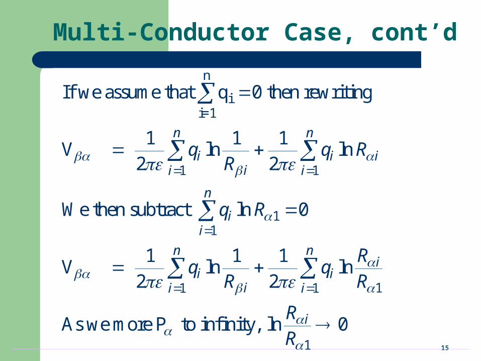
Multi-Conductor Case, cont’d
n
ii=1
1 1
11
11 1
1
If we assume that q 0 then rewriting
1 1 1V ln ln
2 2
We then subtract ln 0
1 1 1V ln ln
2 2
As we more P to infinity, ln 0
n n
i i iii i
n
ii
n ni
i iii i
i
q q RR
q R
Rq q
R R
RR
16
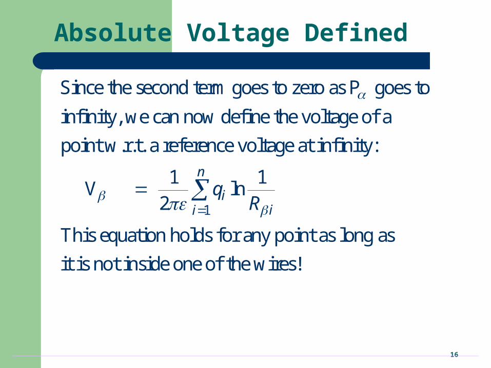
Absolute Voltage Defined
1
Since the second term goes to zero as P goes to
infinity, we can now define the voltage of a
point w.r.t. a reference voltage at infinity:
1 1V ln
2
This equation holds for any point as long a
n
iii
qR
s
it is not inside one of the wires!
17
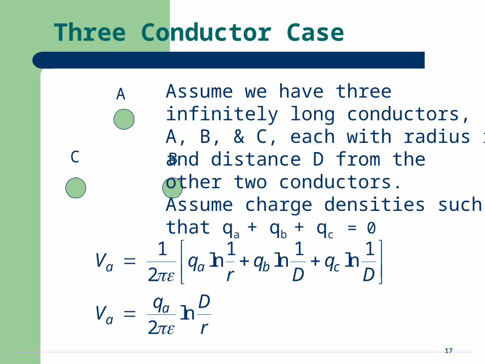
Three Conductor Case
A
BC
Assume we have three infinitely long conductors, A, B, & C, each with radius r and distance D from the other two conductors. Assume charge densities suchthat qa + qb + qc = 0
1 1 1 1ln ln ln
2
ln2
a a b c
aa
V q q qr D D
q DV
r
18
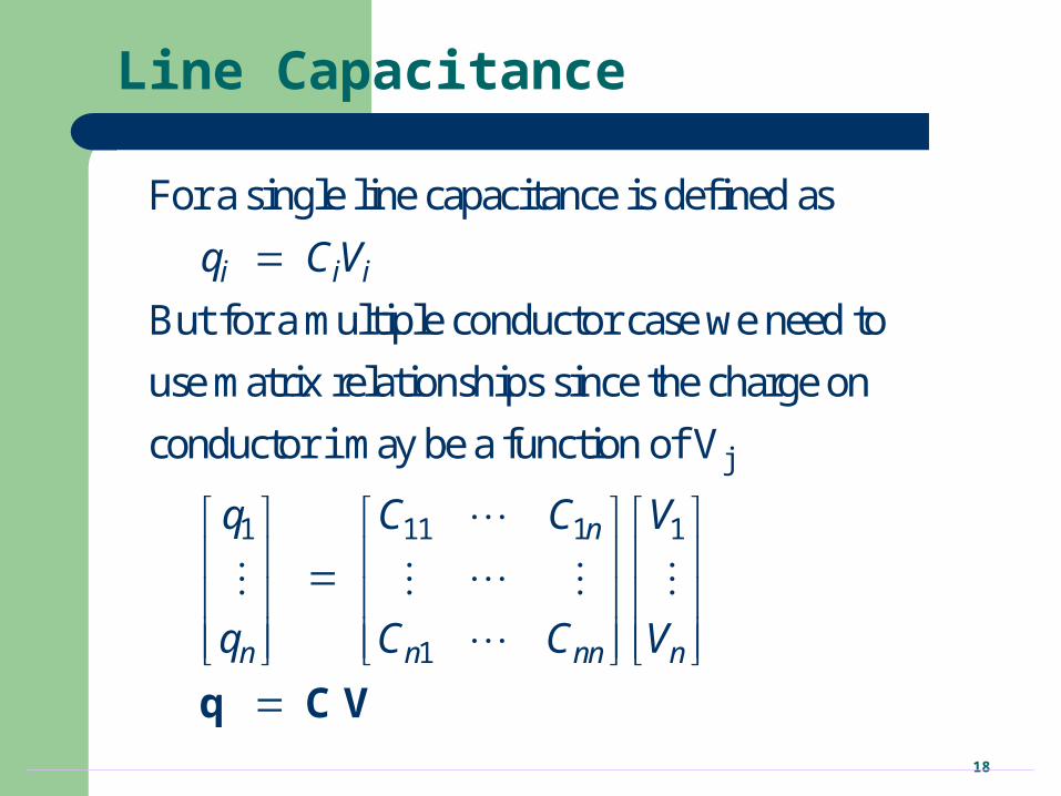
Line Capacitance
j
1 11 1
For a single line capacitance is defined as
But for a multiple conductor case we need to
use matrix relationships since the charge on
conductor i may be a function of V
i i i
n
n
q CV
q C C
q
1
1n nn n
V
C C V
q C V
19
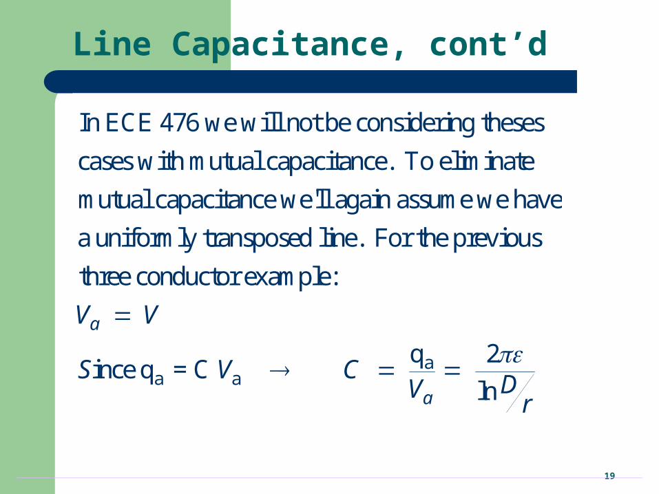
Line Capacitance, cont’d
In ECE 476 we will not be considering theses
cases with mutual capacitance. To eliminate
mutual capacitance we'll again assume we have
a uniformly transposed line. For the previous
three conductor exam
aa a
ple:
q 2ince q = C
ln
a
a
V V
S V CDVr
20
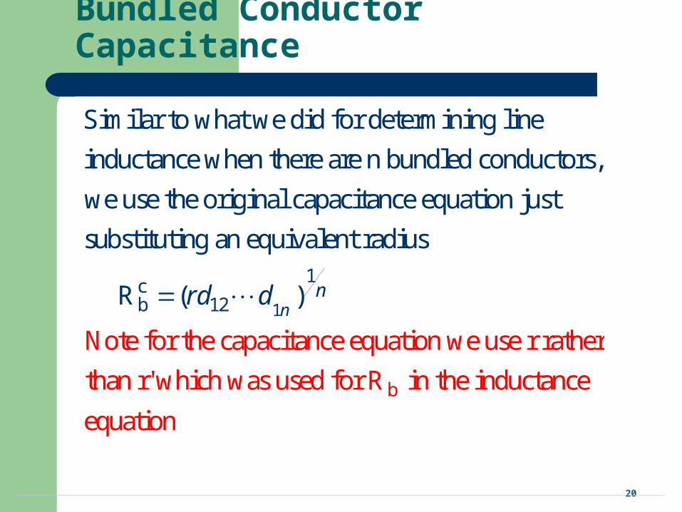
Bundled Conductor Capacitance
1
1cb 12
Similar to what we did for determining line
inductance when there are n bundled conductors,
we use the original capacitance equation just
substituting an equivalent r
Note fo
adius
r t
( )
he
Rn
nrd d
b
capacitance equation we use r rather
than r' which was used for R in the inductance
equation
21
Line Capacitance, cont’d
1
m
13
m
1cb 12
-12o
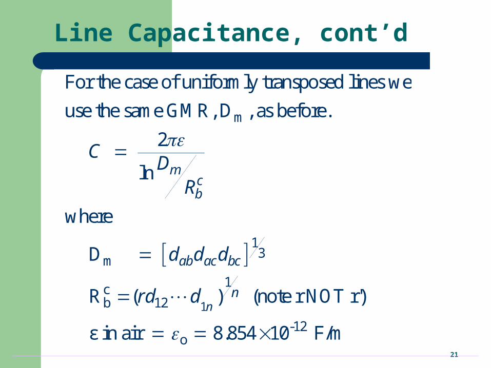
For the case of uniformly transposed lines we
use the same GMR, D , as before.
2
ln
where
D
R ( ) (note r NOT r')
ε in air 8.854 10 F/m
n
mcb
ab ac bc
n
CDR
d d d
rd d
22
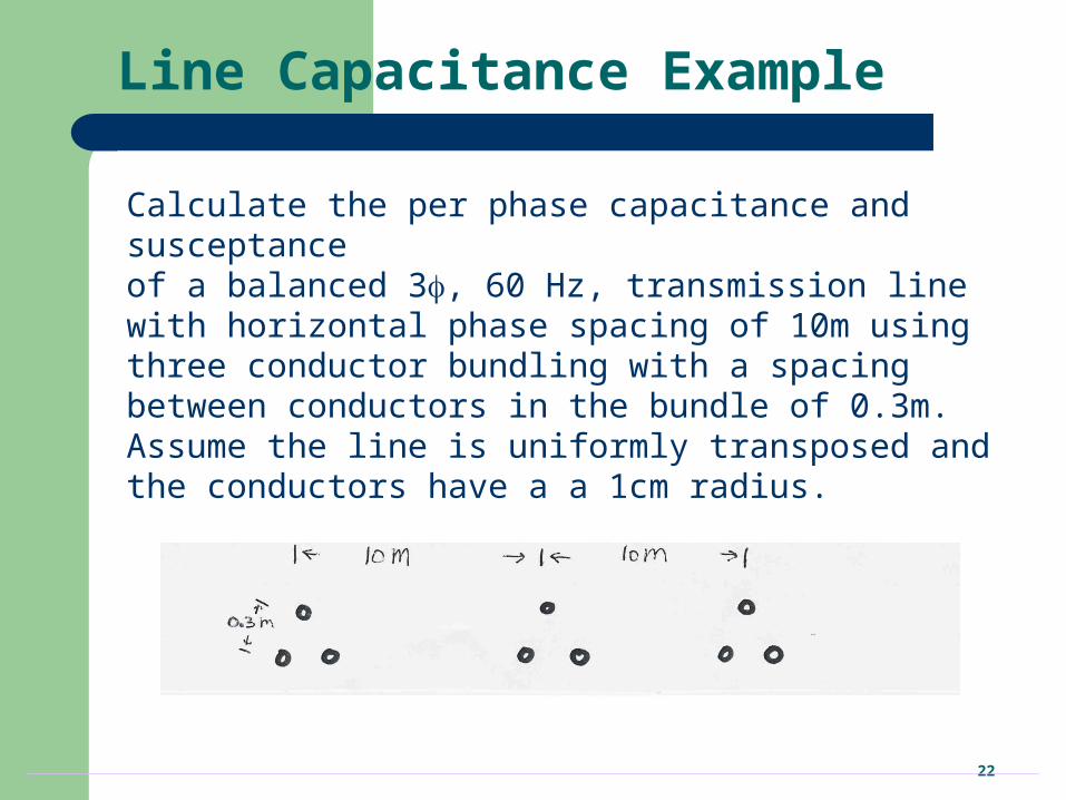
Line Capacitance Example
Calculate the per phase capacitance and susceptance of a balanced 3, 60 Hz, transmission line with horizontal phase spacing of 10m using three conductor bundling with a spacing between conductors in the bundle of 0.3m. Assume the line is uniformly transposed and the conductors have a a 1cm radius.
23
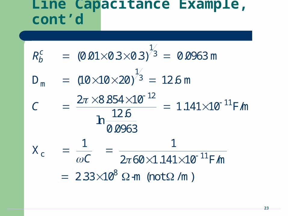
Line Capacitance Example, cont’d
13
13
m
1211
c 11
8
(0.01 0.3 0.3) 0.0963 m
D (10 10 20) 12.6 m
2 8.854 101.141 10 F/m
12.6ln
0.09631 1
X2 60 1.141 10 F/m
2.33 10 -m (not / m)
cbR
C
C
24
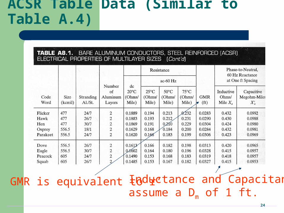
ACSR Table Data (Similar to Table A.4)
Inductance and Capacitance assume a Dm of 1 ft.
GMR is equivalent to r’
25
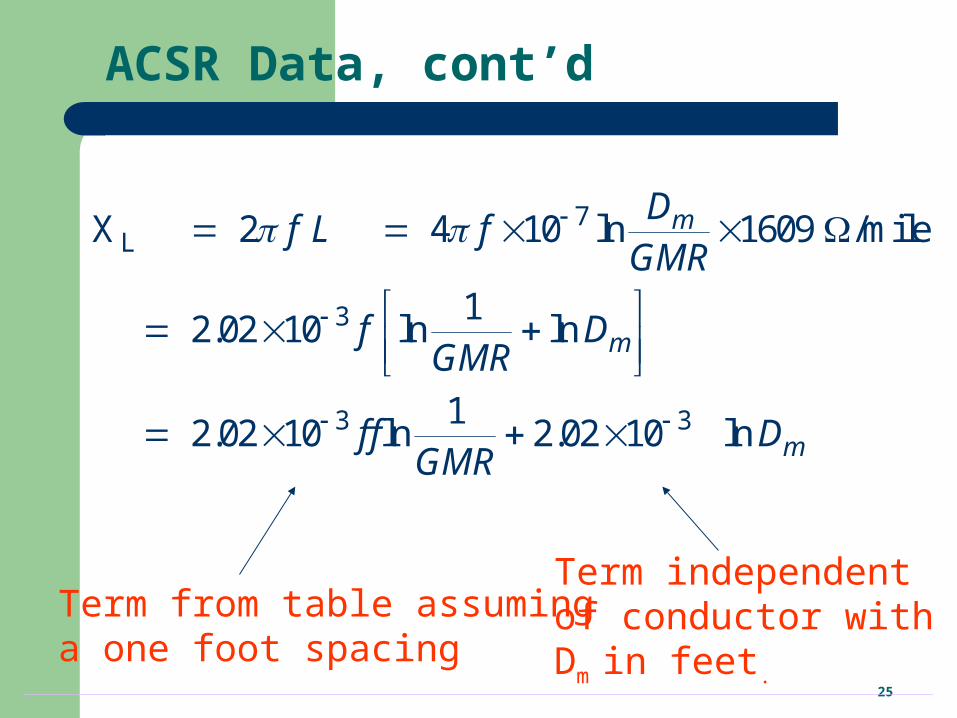
ACSR Data, cont’d
7L
3
3 3
X 2 4 10 ln 1609 /mile
12.02 10 ln ln
12.02 10 ln 2.02 10 ln
m
m
m
Df L f
GMR
f DGMR
f f DGMR
Term from table assuminga one foot spacing
Term independentof conductor withDm in feet.
26
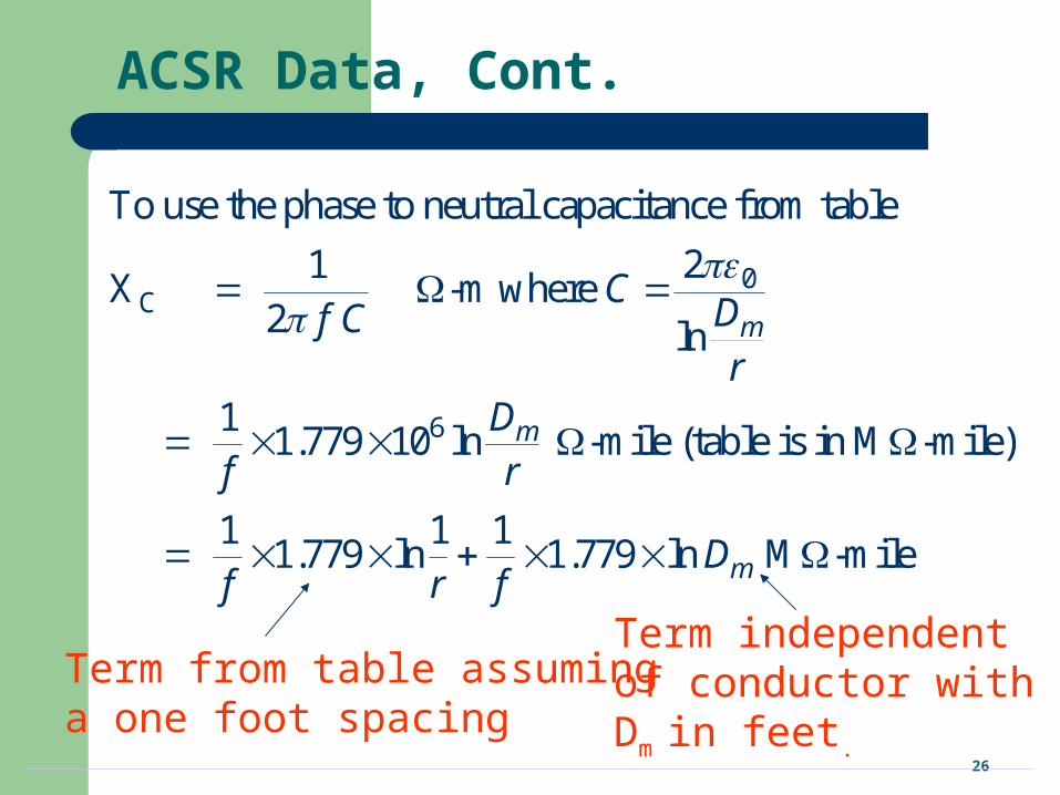
ACSR Data, Cont.
0C
6
To use the phase to neutral capacitance from table
21X -m where
2 ln
11.779 10 ln -mile (table is in M -mile)
1 1 11.779 ln 1.779 ln M -mile
m
m
m
CDf Cr
Df r
Df r f
Term from table assuminga one foot spacing
Term independentof conductor withDm in feet.
27
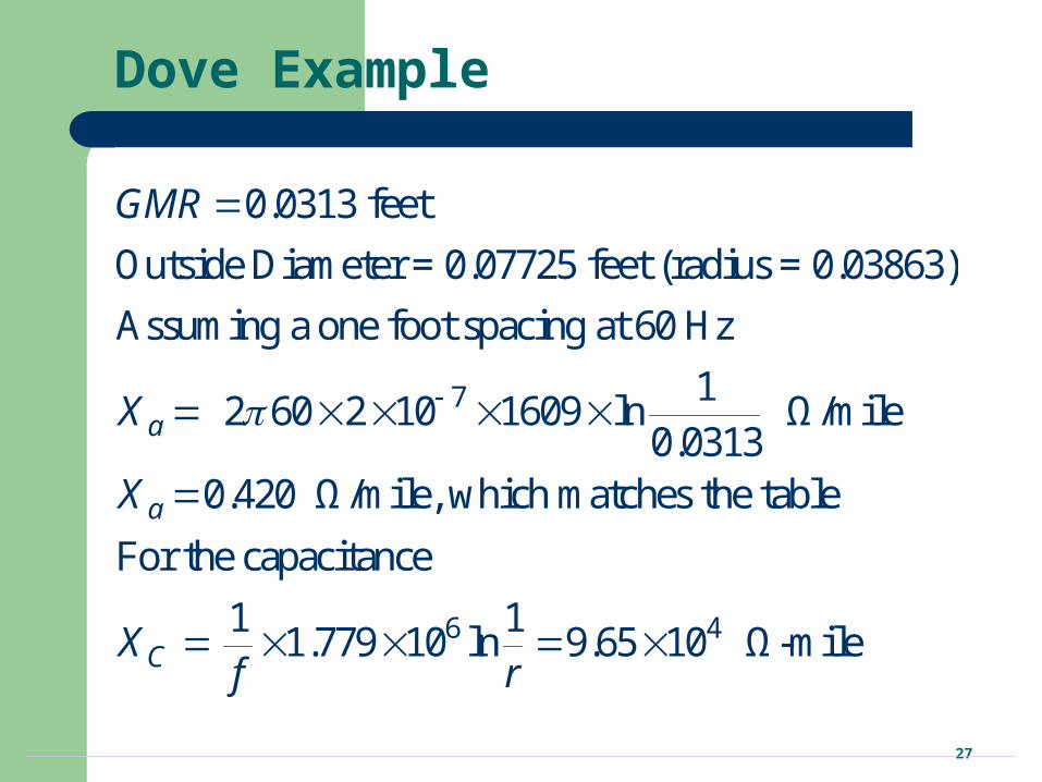
Dove Example
7
0.0313 feet
Outside Diameter = 0.07725 feet (radius = 0.03863)
Assuming a one foot spacing at 60 Hz
12 60 2 10 1609 ln Ω/mile
0.03130.420 Ω/mile, which matches the table
For the capacitance
a
a
C
GMR
X
X
X
6 41 11.779 10 ln 9.65 10 Ω-mile
f r
28
Additional Transmission Topics
Multi-circuit lines: Multiple lines often share a common transmission right-of-way. This DOES cause mutual inductance and capacitance, but is often ignored in system analysis.
Cables: There are about 3000 miles of underground ac cables in U.S. Cables are primarily used in urban areas. In a cable the conductors are tightly spaced, (< 1ft) with oil impregnated paper commonly used to provide insulation
– inductance is lower – capacitance is higher, limiting cable length
29
Additional Transmission topics
Ground wires: Transmission lines are usually protected from lightning strikes with a ground wire. This topmost wire (or wires) helps to attenuate the transient voltages/currents that arise during a lighting strike. The ground wire is typically grounded at each pole.
Corona discharge: Due to high electric fields around lines, the air molecules become ionized. This causes a crackling sound and may cause the line to glow!
30
Additional Transmission topics
Shunt conductance: Usually ignored. A small current may flow through contaminants on insulators.
DC Transmission: Because of the large fixed cost necessary to convert ac to dc and then back to ac, dc transmission is only practical for several specialized applications
– long distance overhead power transfer (> 400 miles)– long cable power transfer such as underwater– providing an asynchronous means of joining different power
systems (such as the Eastern and Western grids).
31
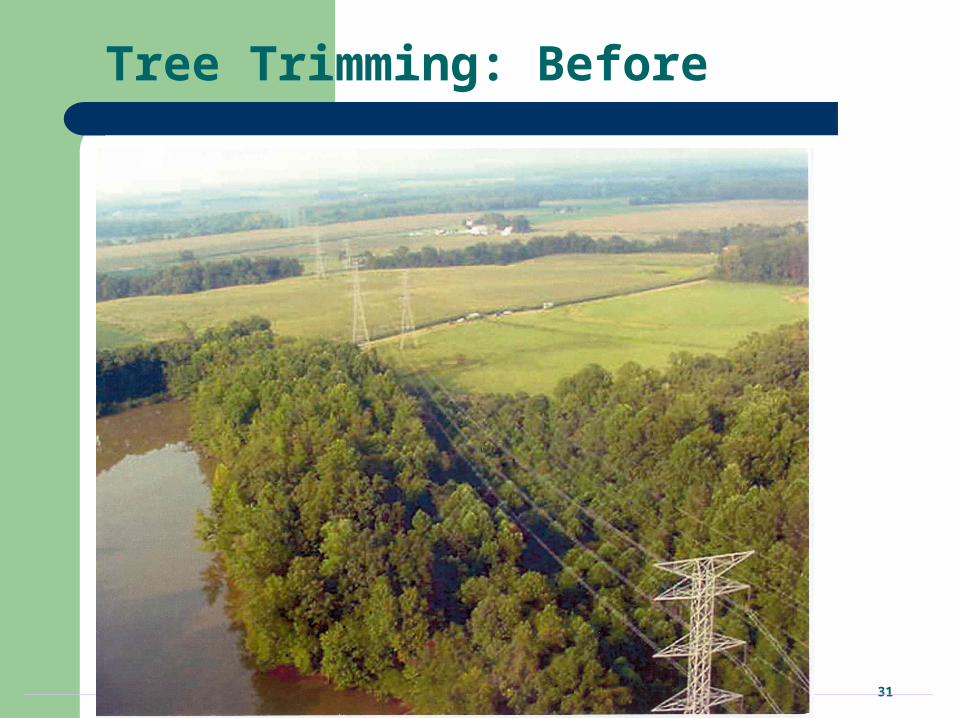
Tree Trimming: Before
32
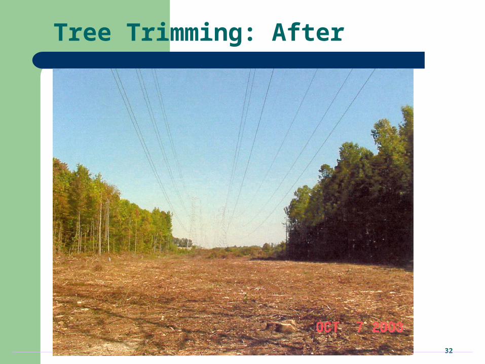
Tree Trimming: After
33
Transmission Line Models
Previous lectures have covered how to calculate the distributed inductance, capacitance and resistance of transmission lines.
In this section we will use these distributed parameters to develop the transmission line models used in power system analysis.
34
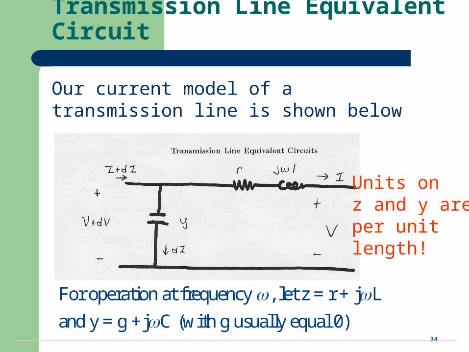
Transmission Line Equivalent Circuit
Our current model of a transmission line is shown below
For operation at frequency , let z = r + j L
and y = g +j C (with g usually equal 0)
Units on z and y areper unit length!
35
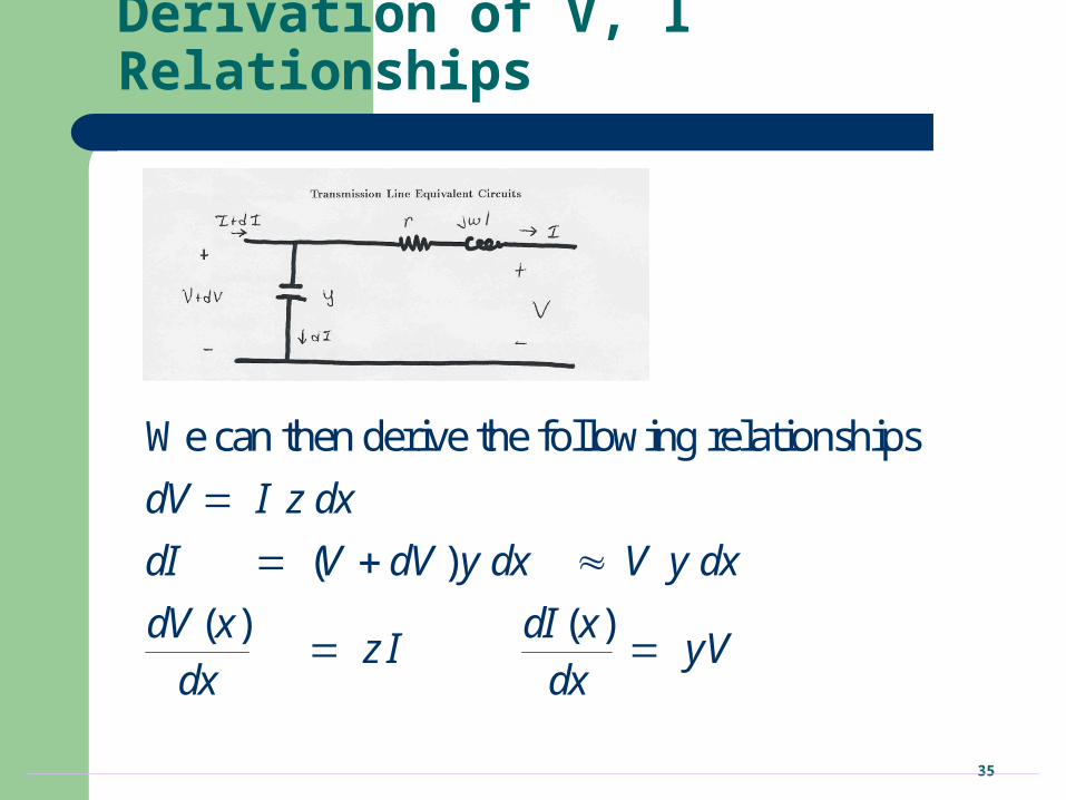
Derivation of V, I Relationships
We can then derive the following relationships:
( )
( ) ( )
dV I z dx
dI V dV y dx V y dx
dV x dI xz I yV
dx dx
36
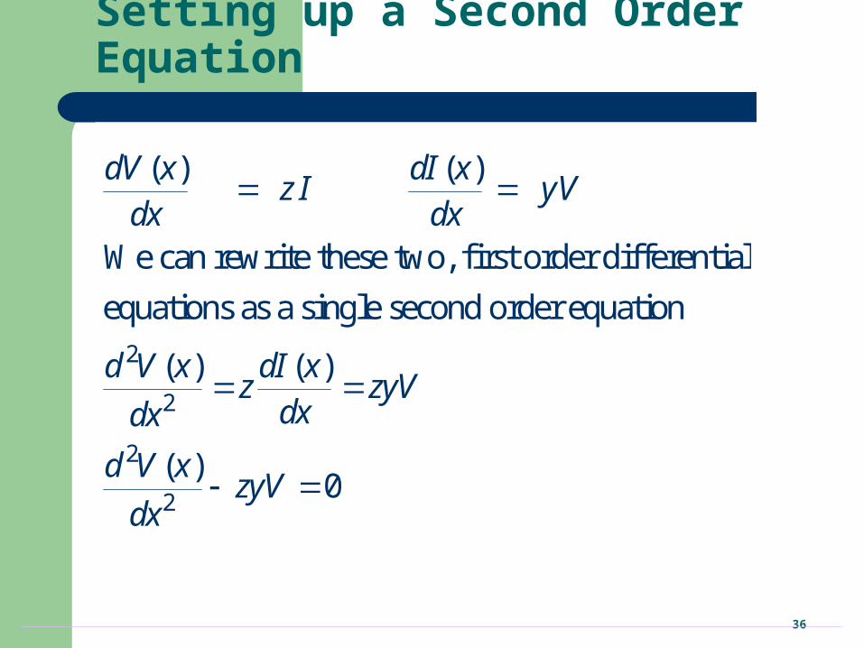
Setting up a Second Order Equation
2
2
2
2
( ) ( )
We can rewrite these two, first order differential
equations as a single second order equation
( ) ( )
( )0
dV x dI xz I yV
dx dx
d V x dI xz zyVdxdx
d V xzyV
dx
37
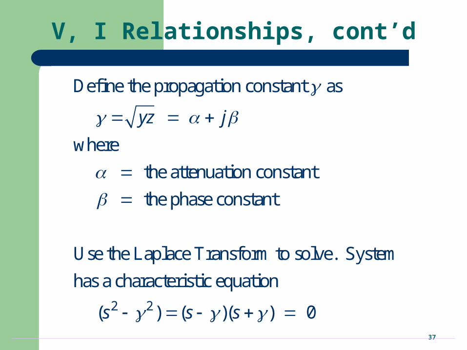
V, I Relationships, cont’d
2 2
Define the propagation constant as
where
the attenuation constant
the phase constant
Use the Laplace Transform to solve. System
has a characteristic equation
( ) ( )( ) 0
yz j
s s s
38
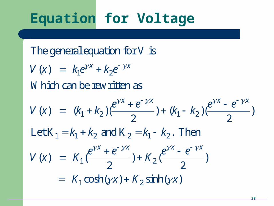
Equation for Voltage
1 2
1 2 1 2
1 1 2 2 1 2
1 2
1 2
The general equation for V is
( )
Which can be rewritten as
( ) ( )( ) ( )( )2 2
Let K and K . Then
( ) ( ) ( )2 2
cosh( ) sinh( )
x x
x x x x
x x x x
V x k e k e
e e e eV x k k k k
k k k k
e e e eV x K K
K x K x
39
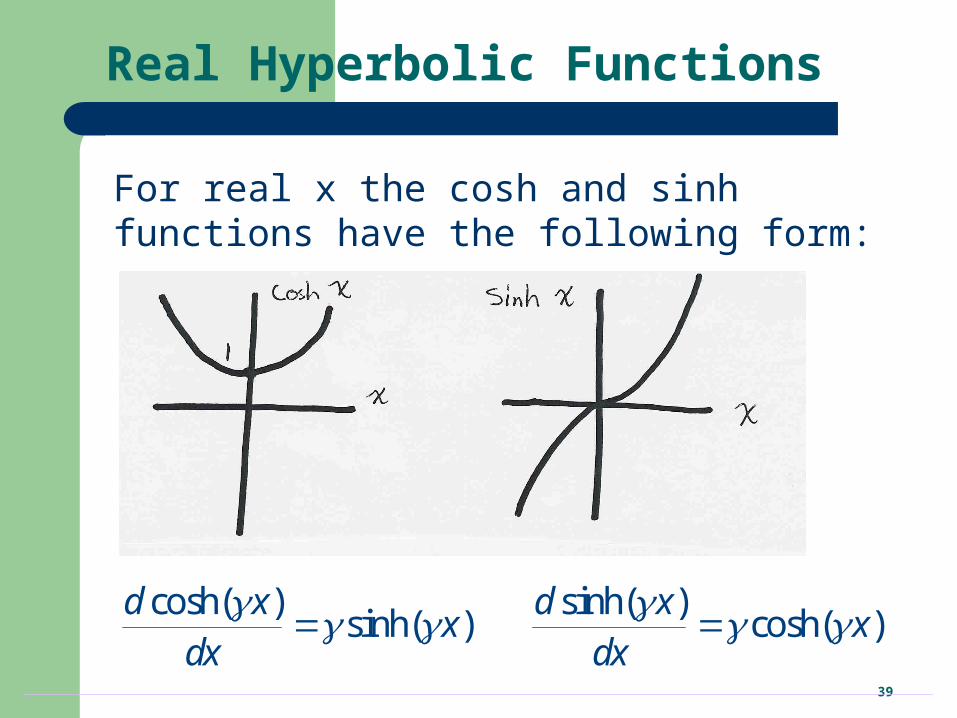
Real Hyperbolic Functions
For real x the cosh and sinh functions have the following form:
cosh( ) sinh( )sinh( ) cosh( )
d x d xx x
dx dx
40
Complex Hyperbolic Functions
For x = + j the cosh and sinh functions have the following form
cosh cosh cos sinh sin
sinh sinh cos cosh sin
x j
x j