Embed Size (px)
Citation preview
8/3/2019 Led Circuits
http://slidepdf.com/reader/full/led-circuits 1/18
This { BELOW }one looks like a pair of eyesslowly brightening and then dimming over and over again. I really like this circuit. I built severala while back and put them in plastic Easter eggs. I drilled out holes for the eyes and put theLED's through the holes. Then put them in bushes around the yard to give the appearance of ghostly eyes. This is the circuit I used...
If you hard wire this circuit onto a perf board, it can be very small and fit together with a 9V battery into anormal sized plastic Easter egg.Bill updated his circuit in 2001 by adding a few more LED's that alternate.
8/3/2019 Led Circuits
http://slidepdf.com/reader/full/led-circuits 2/18
The values I noted on the picture {below }will give you a cycle of about 10 seconds, LED on for 5secs, LED off for 5 secs. Using a different capacitor will change the blink rate. A 10uF capacitorwill blink every second, a 1000uF capacitor will have a 100 secs cycle, always at a 50% on/off ratio. Capacitors are rated on their voltage also, make sure you use a higher voltage rating thanthe voltage of your battery.
Figure 1
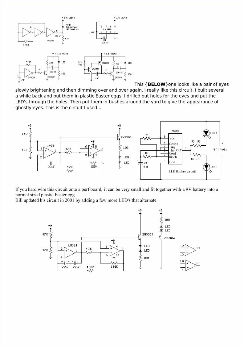
Astable Flip-Flop Circuits
The familiar astable flip-flop circuit is a handy configuration formaking flashers or generating squarewaves. Here is a typicalalternating LED flasher with the LEDs in the emitters instead of collectors as is normally done. (There is another good reason toput them in the emitters - see Karen's note below. ) The biasresistors are directly connected to the supply and are chosen tohave a value about 100 times the collector resistor for ordinarygain transistors. The flashing period is approximately theproduct of this resistance and the capacitance which is about 1second for the circuit as shown. The 470 ohm resistors set theLED current and may be reduced for lower battery voltage butremember to also reduce the bias resistors. If no LEDs aredesired, the emitters may be directly connected to ground andtwo out-of-phase voltage squarewaves are available on thecollectors.
8/3/2019 Led Circuits
http://slidepdf.com/reader/full/led-circuits 3/18
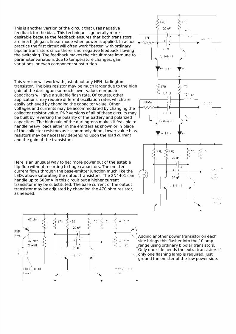
This is another version of the circuit that uses negativefeedback for the bias. This technique is generally moredesirable because the feedback ensures that both transistorsare in a high-gain, linear mode when power is applied. In actualpractice the first circuit will often work "better" with ordinarybipolar transistors since there is no negative feedback slowingthe switching. The feedback makes the circuit more immune toparameter variations due to temperature changes, gainvariations, or even component substitution.
This version will work with just about any NPN darlingtontransistor. The bias resistor may be much larger due to the highgain of the darlington so much lower value, non-polarcapacitors will give a suitable flash rate. Of coures, otherapplications may require different oscillation rates which areeasily achieved by changing the capacitor value. Othervoltages and currents may be accommodated by changing thecollector resistor value. PNP versions of all of these circuits maybe built by reversing the polarity of the battery and polarizedcapacitors. The high gain of the darlingtons makes it feasible tohandle heavy loads either in the emitters as shown or in placeof the collector resistors as is commonly done. Lower value biasresistors may be necessary depending upon the load currentand the gain of the transistors.
Here is an unusual way to get more power out of the astableflip-flop without resorting to huge capacitors. The emittercurrent flows through the base-emitter junction much like the
LEDs above saturating the output transistors. The 2N4401 canhandle up to 600mA in this circuit but a higher currenttransistor may be substituted. The base current of the outputtransistor may be adjusted by changing the 470 ohm resistor,as needed.
Adding another power transistor on eachside brings this flasher into the 10 amprange using ordinary bipolar transistors.Only one side needs the extra transistors if only one flashing lamp is required. Justground the emitter of the low power side.
8/3/2019 Led Circuits
http://slidepdf.com/reader/full/led-circuits 4/18
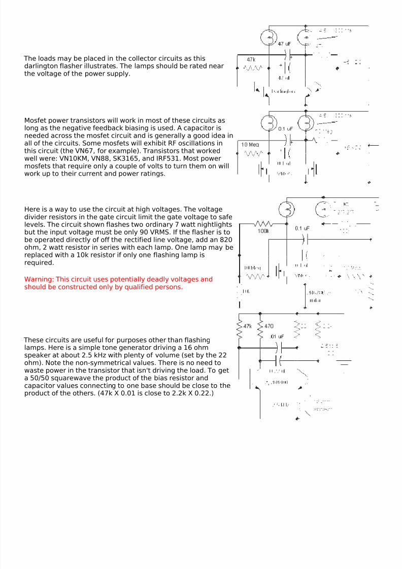
The loads may be placed in the collector circuits as thisdarlington flasher illustrates. The lamps should be rated nearthe voltage of the power supply.
Mosfet power transistors will work in most of these circuits aslong as the negative feedback biasing is used. A capacitor isneeded across the mosfet circuit and is generally a good idea inall of the circuits. Some mosfets will exhibit RF oscillations inthis circuit (the VN67, for example). Transistors that workedwell were: VN10KM, VN88, SK3165, and IRF531. Most powermosfets that require only a couple of volts to turn them on willwork up to their current and power ratings.
Here is a way to use the circuit at high voltages. The voltagedivider resistors in the gate circuit limit the gate voltage to safelevels. The circuit shown flashes two ordinary 7 watt nightlightsbut the input voltage must be only 90 VRMS. If the flasher is tobe operated directly of off the rectified line voltage, add an 820ohm, 2 watt resistor in series with each lamp. One lamp may bereplaced with a 10k resistor if only one flashing lamp isrequired.
Warning: This circuit uses potentially deadly voltages andshould be constructed only by qualified persons.
These circuits are useful for purposes other than flashinglamps. Here is a simple tone generator driving a 16 ohmspeaker at about 2.5 kHz with plenty of volume (set by the 22ohm). Note the non-symmetrical values. There is no need towaste power in the transistor that isn't driving the load. To geta 50/50 squarewave the product of the bias resistor andcapacitor values connecting to one base should be close to theproduct of the others. (47k X 0.01 is close to 2.2k X 0.22.)
8/3/2019 Led Circuits
http://slidepdf.com/reader/full/led-circuits 5/18
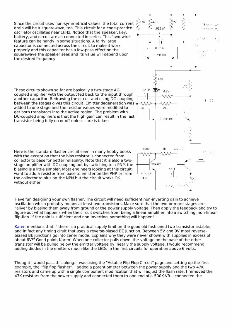
Since the circuit uses non-symmetrical values, the total currentdrain will be a squarewave, too. This circuit for a code-practiceoscillator oscillates near 1kHz. Notice that the speaker, key,battery, and circuit are all connected in series. This "two-wire"feature can be handy in some situations. A fairly largecapacitor is connected across the circuit to make it workproperly and this capacitor has a low-pass effect on thesquarewave the speaker sees and its value will depend uponthe desired frequency.
These circuits shown so far are basically a two-stage AC-coupled amplifier with the output fed back to the input throughanother capacitor. Redrawing the circuit and using DC-couplingbetween the stages gives this circuit. Emitter degeneration wasadded to one stage and the resistor values were modified toget both transistors into the active region. The problem withDC-coupled amplifiers is that the high gain can result in the lasttransistor being fully on or off unless care is taken.
Here is the standard flasher circuit seen in many hobby bookswith the exception that the bias resistor is connected fromcollector to base for better reliability. Note that it is also a two-stage amplifier with DC coupling but by switching to a PNP, thebiasing is a little simpler. Most engineers looking at this circuitwant to add a resistor from base to emitter on the PNP or fromthe collector to plus on the NPN but the circuit works OK without either.
Have fun designing your own flasher. The circuit will need sufficient non-inverting gain to achieveoscillation which probably means at least two transistors. Make sure that the two or more stages are"alive" by biasing them away from ground or the power supply voltage. Then apply the feedback and try tofigure out what happens when the circuit switches from being a linear amplifier into a switching, non-linearflip-flop. If the gain is sufficient and non inverting, something will happen!
Karen mentions that, " there is a practical supply limit on the good old fashioned two transistor astable,and in fact any timing ciruit that uses a reverse-biased BE junction. Between 5V and 9V most reverse-biased BE junctions go into zener mode. Explains why they were never shown with supplies in excess of about 6V!" Good point, Karen! When one collector pulls down, the voltage on the base of the othertransistor will be pulled below the emitter voltage by nearly the supply voltage. I would recommendadding diodes in the emitters much like the LEDs in the first circuits for operation above 6 volts.
Thought I would pass this along. I was using the "Astable Flip Flop Circuit" page and setting up the firstexample, the "flip flop flasher". I added a potentiometer between the power supply and the two 47K resistors and came up with a single component modification that will adjust the flash rate. I removed the47K resistors from the power supply and connected them to one end of a 500K VR. I connected the
8/3/2019 Led Circuits
http://slidepdf.com/reader/full/led-circuits 6/18
opposite end of the 500K VR to the power supply. The center tap gets connected to either side of the VRproducing a 0 - 500K (slow to fast) or 500K - 0 (fast to slow) range.
Trial and error shows that the second circuit, "With negative feedback bias", can be adjustable using a 10kresistor and a 0-100k variable resistor in series between the two transistor bases.
Jay Herde Louisville KY
Thanks Jay!
Jay's first modification connects the bases together somewhat but since one is directly connected to thecollector of the other transistor through the capacitor, the switching still occurs. There might be a problemif the potentiometer is much higher in resistance than the resistors, especially if the transistors do nothave similar characteristics. A small capacitor, maybe 10% of the timing capacitors, connected to groundat the junction of the bias resistors and potentiometer might fix any problem. Jay's worked with a pot 10times bigger than the resistor so perhaps the problem is minimal.
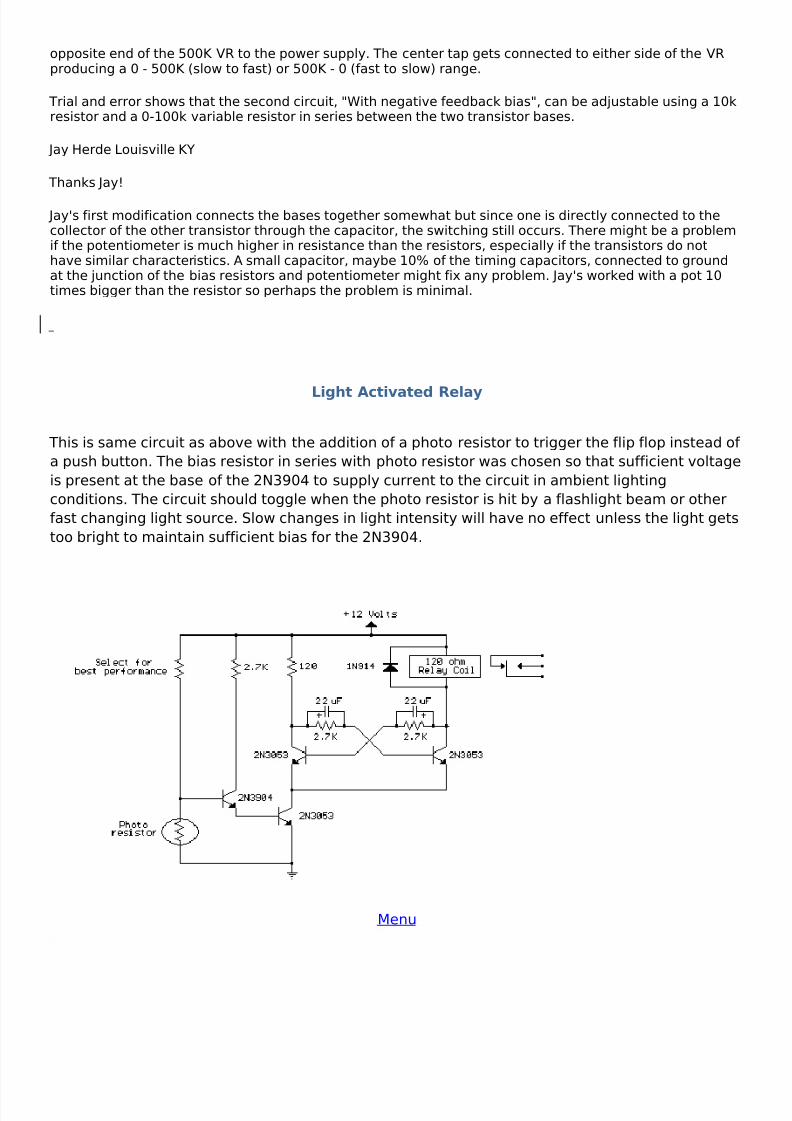
Light Activated Relay
This is same circuit as above with the addition of a photo resistor to trigger the flip flop instead of a push button. The bias resistor in series with photo resistor was chosen so that sufficient voltageis present at the base of the 2N3904 to supply current to the circuit in ambient lightingconditions. The circuit should toggle when the photo resistor is hit by a flashlight beam or otherfast changing light source. Slow changes in light intensity will have no effect unless the light getstoo bright to maintain sufficient bias for the 2N3904.
Menu
8/3/2019 Led Circuits
http://slidepdf.com/reader/full/led-circuits 7/18
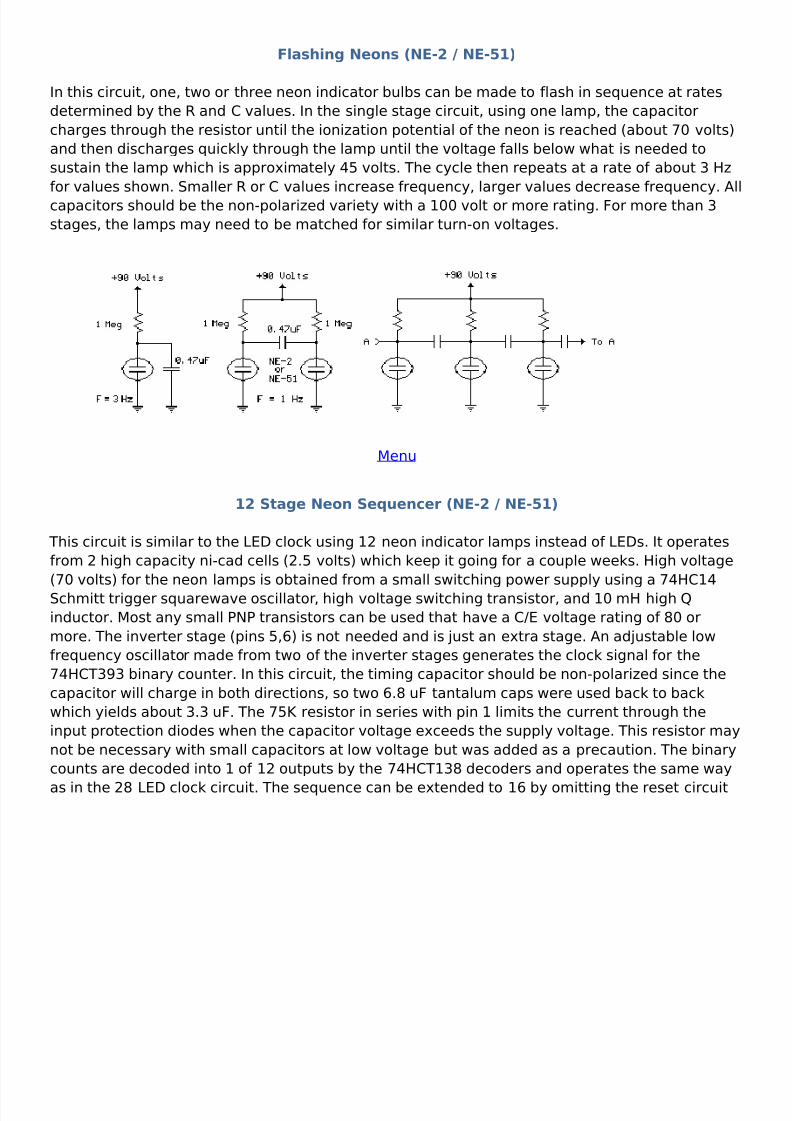
Flashing Neons (NE-2 / NE-51)
In this circuit, one, two or three neon indicator bulbs can be made to flash in sequence at ratesdetermined by the R and C values. In the single stage circuit, using one lamp, the capacitorcharges through the resistor until the ionization potential of the neon is reached (about 70 volts)and then discharges quickly through the lamp until the voltage falls below what is needed tosustain the lamp which is approximately 45 volts. The cycle then repeats at a rate of about 3 Hzfor values shown. Smaller R or C values increase frequency, larger values decrease frequency. Allcapacitors should be the non-polarized variety with a 100 volt or more rating. For more than 3stages, the lamps may need to be matched for similar turn-on voltages.
Menu
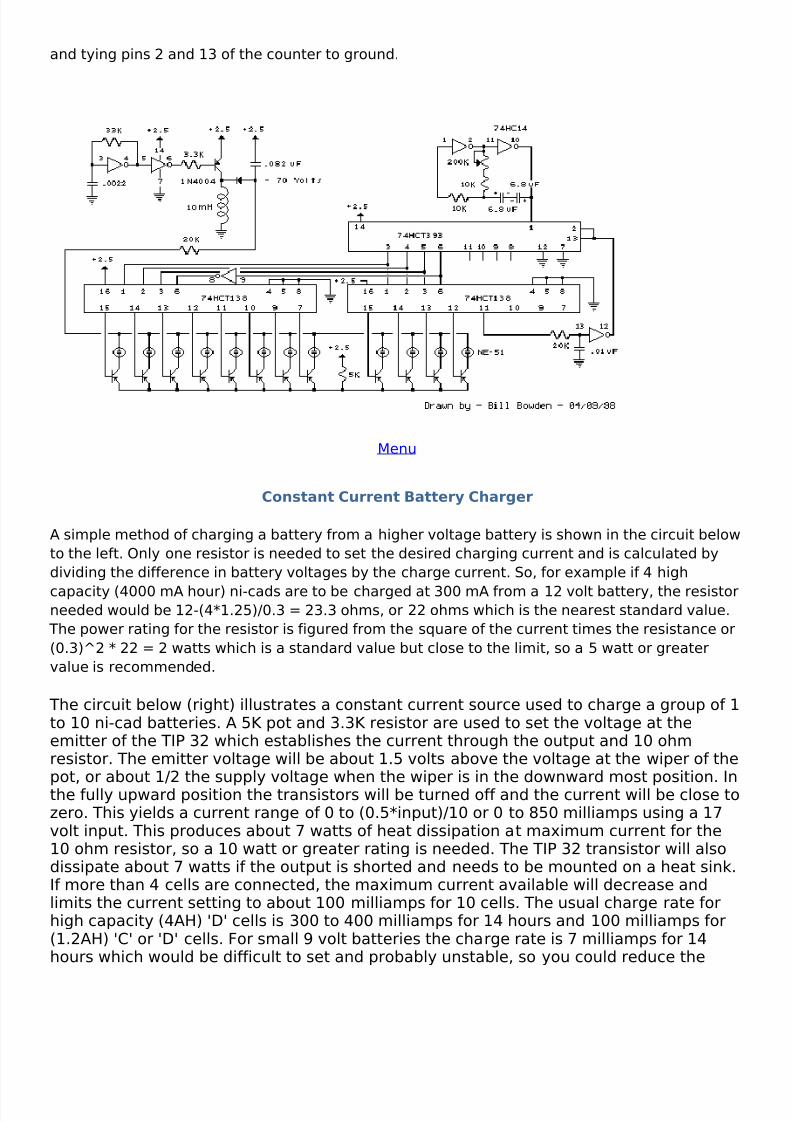
12 Stage Neon Sequencer (NE-2 / NE-51)
This circuit is similar to the LED clock using 12 neon indicator lamps instead of LEDs. It operatesfrom 2 high capacity ni-cad cells (2.5 volts) which keep it going for a couple weeks. High voltage(70 volts) for the neon lamps is obtained from a small switching power supply using a 74HC14Schmitt trigger squarewave oscillator, high voltage switching transistor, and 10 mH high Qinductor. Most any small PNP transistors can be used that have a C/E voltage rating of 80 ormore. The inverter stage (pins 5,6) is not needed and is just an extra stage. An adjustable lowfrequency oscillator made from two of the inverter stages generates the clock signal for the74HCT393 binary counter. In this circuit, the timing capacitor should be non-polarized since thecapacitor will charge in both directions, so two 6.8 uF tantalum caps were used back to backwhich yields about 3.3 uF. The 75K resistor in series with pin 1 limits the current through theinput protection diodes when the capacitor voltage exceeds the supply voltage. This resistor maynot be necessary with small capacitors at low voltage but was added as a precaution. The binarycounts are decoded into 1 of 12 outputs by the 74HCT138 decoders and operates the same way
as in the 28 LED clock circuit. The sequence can be extended to 16 by omitting the reset circuit
8/3/2019 Led Circuits
http://slidepdf.com/reader/full/led-circuits 8/18
and tying pins 2 and 13 of the counter to ground.
Menu
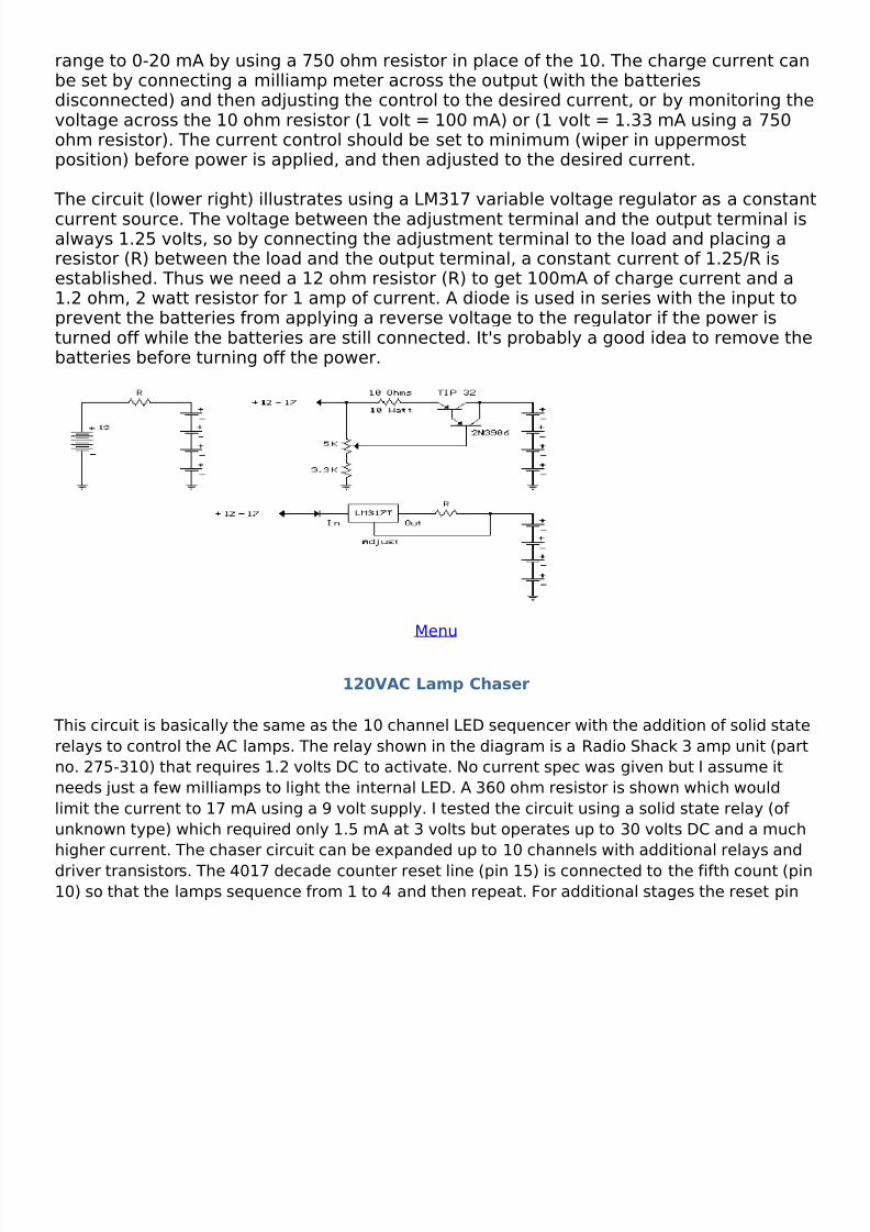
Constant Current Battery Charger
A simple method of charging a battery from a higher voltage battery is shown in the circuit belowto the left. Only one resistor is needed to set the desired charging current and is calculated bydividing the difference in battery voltages by the charge current. So, for example if 4 high
capacity (4000 mA hour) ni-cads are to be charged at 300 mA from a 12 volt battery, the resistorneeded would be 12-(4*1.25)/0.3 = 23.3 ohms, or 22 ohms which is the nearest standard value.
The power rating for the resistor is figured from the square of the current times the resistance or(0.3)^2 * 22 = 2 watts which is a standard value but close to the limit, so a 5 watt or greatervalue is recommended.
The circuit below (right) illustrates a constant current source used to charge a group of 1to 10 ni-cad batteries. A 5K pot and 3.3K resistor are used to set the voltage at theemitter of the TIP 32 which establishes the current through the output and 10 ohmresistor. The emitter voltage will be about 1.5 volts above the voltage at the wiper of thepot, or about 1/2 the supply voltage when the wiper is in the downward most position. Inthe fully upward position the transistors will be turned off and the current will be close tozero. This yields a current range of 0 to (0.5*input)/10 or 0 to 850 milliamps using a 17volt input. This produces about 7 watts of heat dissipation at maximum current for the10 ohm resistor, so a 10 watt or greater rating is needed. The TIP 32 transistor will alsodissipate about 7 watts if the output is shorted and needs to be mounted on a heat sink.If more than 4 cells are connected, the maximum current available will decrease andlimits the current setting to about 100 milliamps for 10 cells. The usual charge rate forhigh capacity (4AH) 'D' cells is 300 to 400 milliamps for 14 hours and 100 milliamps for(1.2AH) 'C' or 'D' cells. For small 9 volt batteries the charge rate is 7 milliamps for 14hours which would be difficult to set and probably unstable, so you could reduce the
8/3/2019 Led Circuits
http://slidepdf.com/reader/full/led-circuits 9/18
range to 0-20 mA by using a 750 ohm resistor in place of the 10. The charge current canbe set by connecting a milliamp meter across the output (with the batteriesdisconnected) and then adjusting the control to the desired current, or by monitoring thevoltage across the 10 ohm resistor (1 volt = 100 mA) or (1 volt = 1.33 mA using a 750ohm resistor). The current control should be set to minimum (wiper in uppermostposition) before power is applied, and then adjusted to the desired current.
The circuit (lower right) illustrates using a LM317 variable voltage regulator as a constantcurrent source. The voltage between the adjustment terminal and the output terminal isalways 1.25 volts, so by connecting the adjustment terminal to the load and placing aresistor (R) between the load and the output terminal, a constant current of 1.25/R isestablished. Thus we need a 12 ohm resistor (R) to get 100mA of charge current and a1.2 ohm, 2 watt resistor for 1 amp of current. A diode is used in series with the input toprevent the batteries from applying a reverse voltage to the regulator if the power isturned off while the batteries are still connected. It's probably a good idea to remove thebatteries before turning off the power.
Menu
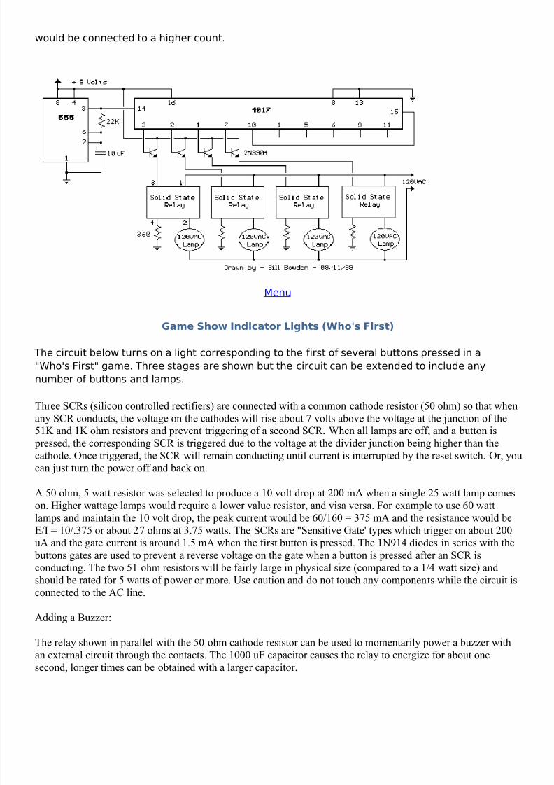
120VAC Lamp Chaser
This circuit is basically the same as the 10 channel LED sequencer with the addition of solid staterelays to control the AC lamps. The relay shown in the diagram is a Radio Shack 3 amp unit (partno. 275-310) that requires 1.2 volts DC to activate. No current spec was given but I assume itneeds just a few milliamps to light the internal LED. A 360 ohm resistor is shown which wouldlimit the current to 17 mA using a 9 volt supply. I tested the circuit using a solid state relay (of unknown type) which required only 1.5 mA at 3 volts but operates up to 30 volts DC and a muchhigher current. The chaser circuit can be expanded up to 10 channels with additional relays anddriver transistors. The 4017 decade counter reset line (pin 15) is connected to the fifth count (pin10) so that the lamps sequence from 1 to 4 and then repeat. For additional stages the reset pin
8/3/2019 Led Circuits
http://slidepdf.com/reader/full/led-circuits 10/18
would be connected to a higher count.
Menu
Game Show Indicator Lights (Who's First)
The circuit below turns on a light corresponding to the first of several buttons pressed in a"Who's First" game. Three stages are shown but the circuit can be extended to include anynumber of buttons and lamps.
Three SCRs (silicon controlled rectifiers) are connected with a common cathode resistor (50 ohm) so that whenany SCR conducts, the voltage on the cathodes will rise about 7 volts above the voltage at the junction of the51K and 1K ohm resistors and prevent triggering of a second SCR. When all lamps are off, and a button is
pressed, the corresponding SCR is triggered due to the voltage at the divider junction being higher than thecathode. Once triggered, the SCR will remain conducting until current is interrupted by the reset switch. Or, youcan just turn the power off and back on.
A 50 ohm, 5 watt resistor was selected to produce a 10 volt drop at 200 mA when a single 25 watt lamp comeson. Higher wattage lamps would require a lower value resistor, and visa versa. For example to use 60 wattlamps and maintain the 10 volt drop, the peak current would be 60/160 = 375 mA and the resistance would beE/I = 10/.375 or about 27 ohms at 3.75 watts. The SCRs are "Sensitive Gate' types which trigger on about 200uA and the gate current is around 1.5 mA when the first button is pressed. The 1N914 diodes in series with the
buttons gates are used to prevent a reverse voltage on the gate when a button is pressed after an SCR isconducting. The two 51 ohm resistors will be fairly large in physical size (compared to a 1/4 watt size) andshould be rated for 5 watts of power or more. Use caution and do not touch any components while the circuit isconnected to the AC line.
Adding a Buzzer:
The relay shown in parallel with the 50 ohm cathode resistor can be used to momentarily power a buzzer withan external circuit through the contacts. The 1000 uF capacitor causes the relay to energize for about onesecond, longer times can be obtained with a larger capacitor.
8/3/2019 Led Circuits
http://slidepdf.com/reader/full/led-circuits 11/18
Parts List:
Quantity Description Radio Shack Part Number
1 4 Amp/400 Volt Bridge Rectifier 276-11733 Silicon Controlled Rectifier (SCR) NTE54573 120 VAC/ 25 Watt incandescent lamp1 50-100 microfarad/ 200 volt capacitor1 1000 microfarad / 35 volt capacitor 272-10321 50 ohm resistor/ 5 or 10 Watt 271-1333 Push Button Switch (normally open)1 Push Button Switch (normally closed)3 2K resistor, 1/4 watt 271-13254 1N914 Diode1 51K resistor, 1 watt1 2 Amp Fuse 270-10641 Relay (SPDT) 9 Volt DC, 500 ohm coil 275-005
Menu
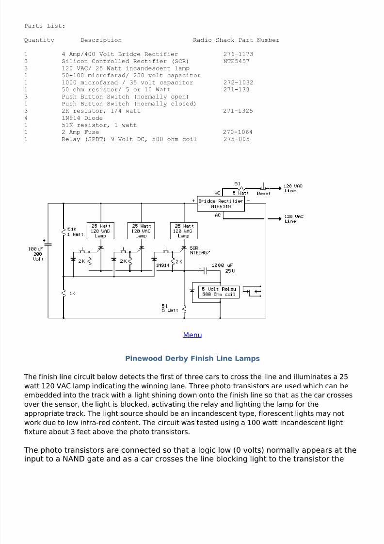
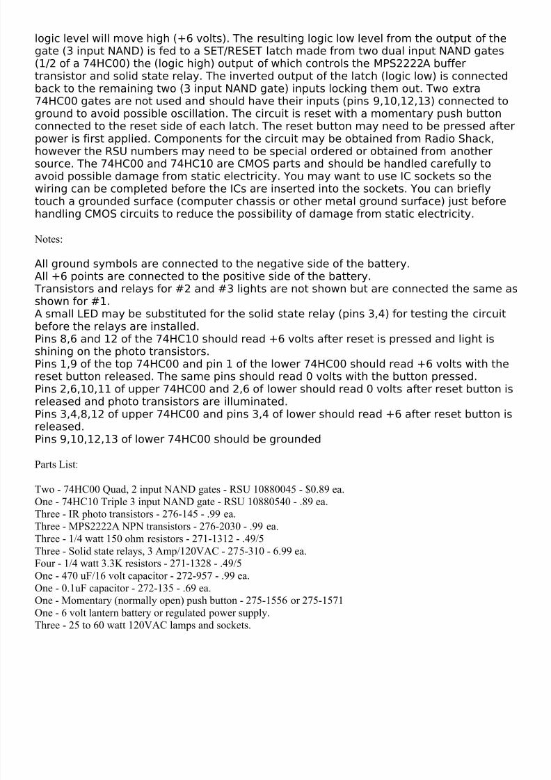
Pinewood Derby Finish Line Lamps
The finish line circuit below detects the first of three cars to cross the line and illuminates a 25watt 120 VAC lamp indicating the winning lane. Three photo transistors are used which can beembedded into the track with a light shining down onto the finish line so that as the car crossesover the sensor, the light is blocked, activating the relay and lighting the lamp for theappropriate track. The light source should be an incandescent type, florescent lights may notwork due to low infra-red content. The circuit was tested using a 100 watt incandescent lightfixture about 3 feet above the photo transistors.
The photo transistors are connected so that a logic low (0 volts) normally appears at theinput to a NAND gate and as a car crosses the line blocking light to the transistor the
8/3/2019 Led Circuits
http://slidepdf.com/reader/full/led-circuits 12/18
logic level will move high (+6 volts). The resulting logic low level from the output of thegate (3 input NAND) is fed to a SET/RESET latch made from two dual input NAND gates(1/2 of a 74HC00) the (logic high) output of which controls the MPS2222A buffertransistor and solid state relay. The inverted output of the latch (logic low) is connectedback to the remaining two (3 input NAND gate) inputs locking them out. Two extra74HC00 gates are not used and should have their inputs (pins 9,10,12,13) connected toground to avoid possible oscillation. The circuit is reset with a momentary push buttonconnected to the reset side of each latch. The reset button may need to be pressed afterpower is first applied. Components for the circuit may be obtained from Radio Shack,however the RSU numbers may need to be special ordered or obtained from anothersource. The 74HC00 and 74HC10 are CMOS parts and should be handled carefully toavoid possible damage from static electricity. You may want to use IC sockets so thewiring can be completed before the ICs are inserted into the sockets. You can brieflytouch a grounded surface (computer chassis or other metal ground surface) just beforehandling CMOS circuits to reduce the possibility of damage from static electricity.
Notes:
All ground symbols are connected to the negative side of the battery.All +6 points are connected to the positive side of the battery.
Transistors and relays for #2 and #3 lights are not shown but are connected the same asshown for #1.A small LED may be substituted for the solid state relay (pins 3,4) for testing the circuitbefore the relays are installed.Pins 8,6 and 12 of the 74HC10 should read +6 volts after reset is pressed and light isshining on the photo transistors.Pins 1,9 of the top 74HC00 and pin 1 of the lower 74HC00 should read +6 volts with thereset button released. The same pins should read 0 volts with the button pressed.Pins 2,6,10,11 of upper 74HC00 and 2,6 of lower should read 0 volts after reset button isreleased and photo transistors are illuminated.Pins 3,4,8,12 of upper 74HC00 and pins 3,4 of lower should read +6 after reset button isreleased.Pins 9,10,12,13 of lower 74HC00 should be grounded
Parts List:
Two - 74HC00 Quad, 2 input NAND gates - RSU 10880045 - $0.89 ea.One - 74HC10 Triple 3 input NAND gate - RSU 10880540 - .89 ea.Three - IR photo transistors - 276-145 - .99 ea.Three - MPS2222A NPN transistors - 276-2030 - .99 ea.Three - 1/4 watt 150 ohm resistors - 271-1312 - .49/5Three - Solid state relays, 3 Amp/120VAC - 275-310 - 6.99 ea.Four - 1/4 watt 3.3K resistors - 271-1328 - .49/5One - 470 uF/16 volt capacitor - 272-957 - .99 ea.One - 0.1uF capacitor - 272-135 - .69 ea.One - Momentary (normally open) push button - 275-1556 or 275-1571One - 6 volt lantern battery or regulated power supply.Three - 25 to 60 watt 120VAC lamps and sockets.
8/3/2019 Led Circuits
http://slidepdf.com/reader/full/led-circuits 13/18
Amateur and Short Wave Radio ElectronicsExperimenter's Web Site
• SWL Page• What's New?• Site Info & Links• VE7BPO's Junk Box•
Guitar Amp• Design Center• Email • Topics 1998 - 2002
RF Preamps
QRPHB Software
Popcorn DC Receiver Mainframe
40 M popcorn Superhet Receiver

8/3/2019 Led Circuits
http://slidepdf.com/reader/full/led-circuits 14/18
Broadband Transformer Topics
Crystal Oscillator Frequency Offsets
Diplexer Topics
RF Filters
Ugly Construction
Selected QRP Reading List
Powdered Iron Toroidal Coating
VFO Topics
30 M DC Receiver Experiment
QRPHB Workshop Ideas
Astable Multivibrator Circuits
QRP Transmitters
Discrete Component RC Audio Filters
Wee Willy 75 M DSB Transceiver
Tuning VFOs with a PN-Junction
Funster 40 M Transceiver
W7ZOI JFET Biasing Tutorial
Miscellaneous Pictures and Circuits
• Topics 2003 - 2005Voltage Probe RF Preamplifier
EMRFD Review
Tapped Cap Impedance Transformation
WA7JHZ SSB 75m Transceiver
Cascode 7 Superhet Receiver
More Active Antenna Experiments
Cascode BJT RF Amp Bias Experiments
Fun with LEDs
8/3/2019 Led Circuits
http://slidepdf.com/reader/full/led-circuits 15/18
Introduction this summer I built several LED projects includingsequential LED chasers (sequentially left to right) and also "Nite-Rider" style which go (sequentially left-right-left-right-etc). Manymore LED schematics can be found on the World Wide Web via aGoogle search. LED projects are great fun for both HAM's and SWL'salike. They are also a lot of fun for children to experiment with.
Currently, I am experimenting with PIC microcontrollers to performLED "tricks".
I also built several very bright LED flashlights which run on a single 1.5 volt battery. For ultra-bright LEDflashlight schematics, check out Dick Cappel's excellent and very informative web site . He has a number of LED driver circuits and other great schematics and theory. To wind the inductor for these LED flashlights, I hadgood success using an FT-37-43 ferrite torroid core. I used at least 40 turns of wire which is generally center tapped.
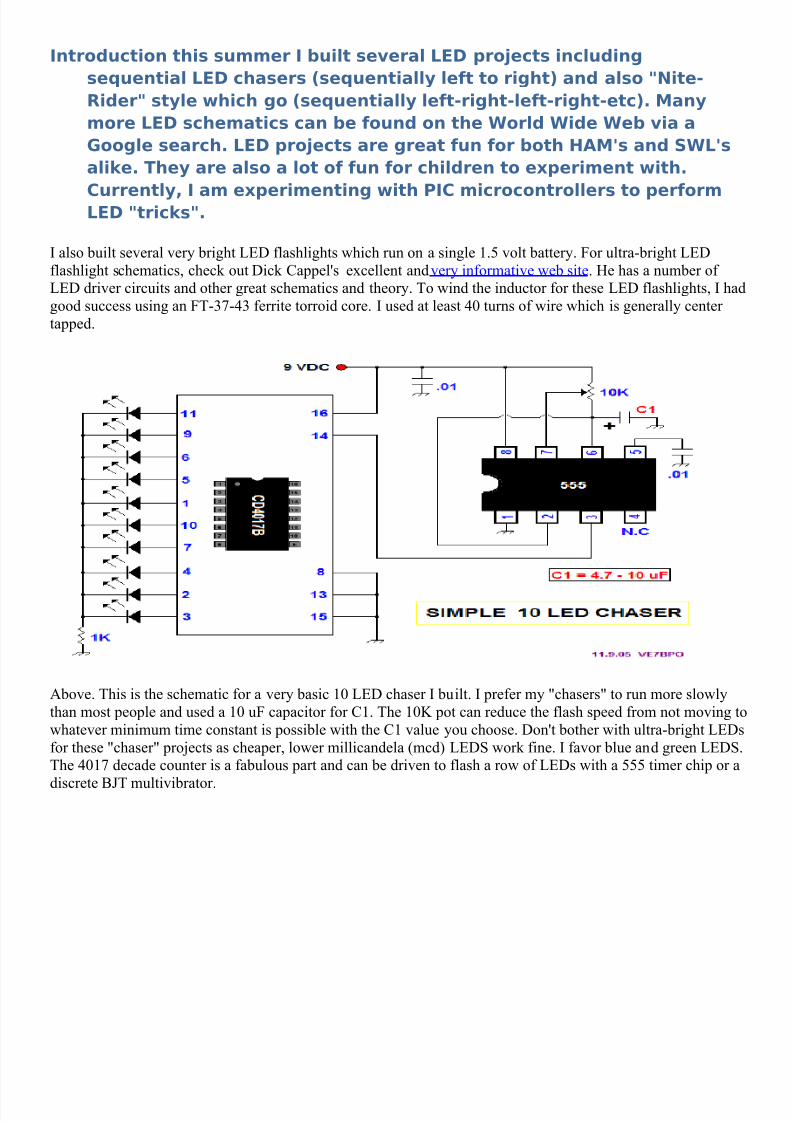
Above. This is the schematic for a very basic 10 LED chaser I built. I prefer my "chasers" to run more slowlythan most people and used a 10 uF capacitor for C1. The 10K pot can reduce the flash speed from not moving towhatever minimum time constant is possible with the C1 value you choose. Don't bother with ultra-bright LEDsfor these "chaser" projects as cheaper, lower millicandela (mcd) LEDS work fine. I favor blue and green LEDS.The 4017 decade counter is a fabulous part and can be driven to flash a row of LEDs with a 555 timer chip or a
discrete BJT multivibrator.
8/3/2019 Led Circuits
http://slidepdf.com/reader/full/led-circuits 16/18
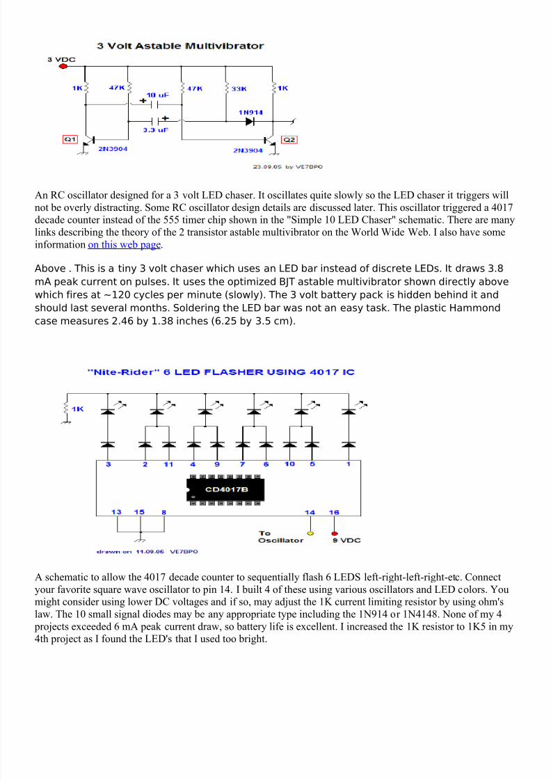
An RC oscillator designed for a 3 volt LED chaser. It oscillates quite slowly so the LED chaser it triggers willnot be overly distracting. Some RC oscillator design details are discussed later. This oscillator triggered a 4017decade counter instead of the 555 timer chip shown in the "Simple 10 LED Chaser" schematic. There are manylinks describing the theory of the 2 transistor astable multivibrator on the World Wide Web. I also have someinformation on this web page .
Above . This is a tiny 3 volt chaser which uses an LED bar instead of discrete LEDs. It draws 3.8mA peak current on pulses. It uses the optimized BJT astable multivibrator shown directly abovewhich fires at ~120 cycles per minute (slowly). The 3 volt battery pack is hidden behind it andshould last several months. Soldering the LED bar was not an easy task. The plastic Hammondcase measures 2.46 by 1.38 inches (6.25 by 3.5 cm).
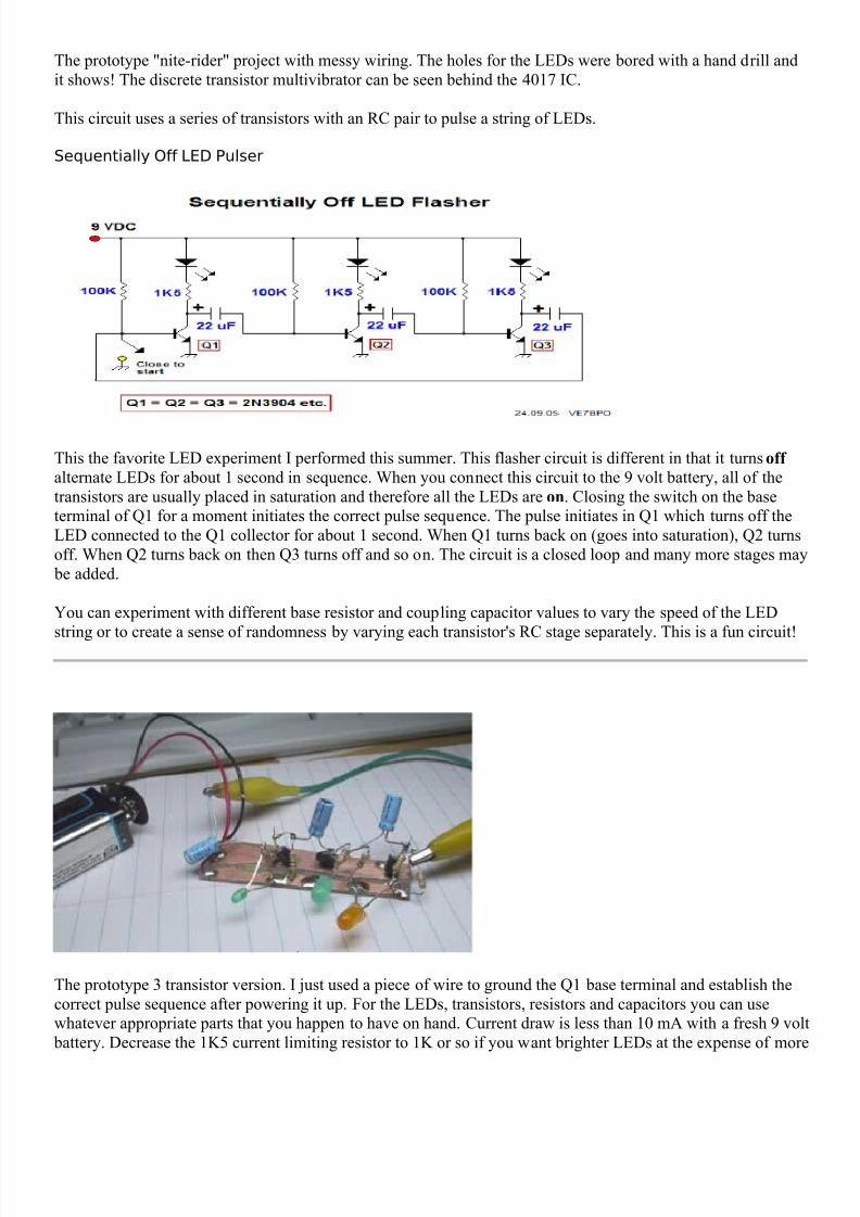
A schematic to allow the 4017 decade counter to sequentially flash 6 LEDS left-right-left-right-etc. Connectyour favorite square wave oscillator to pin 14. I built 4 of these using various oscillators and LED colors. Youmight consider using lower DC voltages and if so, may adjust the 1K current limiting resistor by using ohm'slaw. The 10 small signal diodes may be any appropriate type including the 1N914 or 1N4148. None of my 4
projects exceeded 6 mA peak current draw, so battery life is excellent. I increased the 1K resistor to 1K5 in my4th project as I found the LED's that I used too bright.
8/3/2019 Led Circuits
http://slidepdf.com/reader/full/led-circuits 17/18
The prototype "nite-rider" project with messy wiring. The holes for the LEDs were bored with a hand drill andit shows! The discrete transistor multivibrator can be seen behind the 4017 IC.
This circuit uses a series of transistors with an RC pair to pulse a string of LEDs.
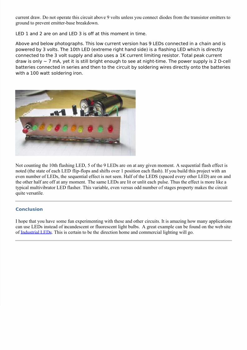
Sequentially Off LED Pulser
This the favorite LED experiment I performed this summer. This flasher circuit is different in that it turns off
alternate LEDs for about 1 second in sequence. When you connect this circuit to the 9 volt battery, all of thetransistors are usually placed in saturation and therefore all the LEDs are on . Closing the switch on the baseterminal of Q1 for a moment initiates the correct pulse sequence. The pulse initiates in Q1 which turns off theLED connected to the Q1 collector for about 1 second. When Q1 turns back on (goes into saturation), Q2 turnsoff. When Q2 turns back on then Q3 turns off and so on. The circuit is a closed loop and many more stages may
be added.
You can experiment with different base resistor and coupling capacitor values to vary the speed of the LED
string or to create a sense of randomness by varying each transistor's RC stage separately. This is a fun circuit!
The prototype 3 transistor version. I just used a piece of wire to ground the Q1 base terminal and establish thecorrect pulse sequence after powering it up. For the LEDs, transistors, resistors and capacitors you can usewhatever appropriate parts that you happen to have on hand. Current draw is less than 10 mA with a fresh 9 volt
battery. Decrease the 1K5 current limiting resistor to 1K or so if you want brighter LEDs at the expense of more
8/3/2019 Led Circuits
http://slidepdf.com/reader/full/led-circuits 18/18
current draw. Do not operate this circuit above 9 volts unless you connect diodes from the transistor emitters toground to prevent emitter-base breakdown.
LED 1 and 2 are on and LED 3 is off at this moment in time.
Above and below photographs. This low current version has 9 LEDs connected in a chain and ispowered by 3 volts. The 10th LED (extreme right hand side) is a flashing LED which is directlyconnected to the 3 volt supply and also uses a 1K current limiting resistor. Total peak current
draw is only ~ 7 mA, yet it is still bright enough to see at night-time. The power supply is 2 D-cellbatteries connected in series and then to the circuit by soldering wires directly onto the batterieswith a 100 watt soldering iron.
Not counting the 10th flashing LED, 5 of the 9 LEDs are on at any given moment. A sequential flash effect isnoted (the state of each LED flip-flops and shifts over 1 position each flash). If you build this project with aneven number of LEDs, the sequential effect is not seen. Half of the LEDS (spaced every other LED) are on and
the other half are off at any moment. The same LEDs are lit or unlit each pulse. Thus the effect is more like atypical multivibrator LED flasher. This variable, even versus odd number of stages property makes the circuitquite versatile.
Conclusion
I hope that you have some fun experimenting with these and other circuits. It is amazing how many applicationscan use LEDs instead of incandescent or fluorescent light bulbs. A great example can be found on the web siteof Industrial LEDs . This is certain to be the direction home and commercial lighting will go.