Embed Size (px)
Citation preview
Operating Instructions BLHE Series
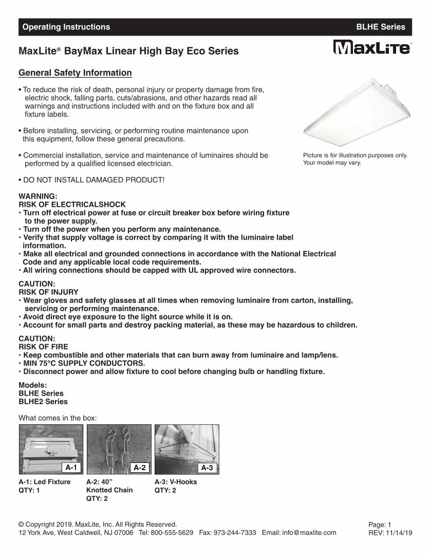
MaxLite BayMax Linear High Bay Eco Series
• To reduce the risk of death, personal injury or property damage from fire, electric shock, falling parts, cuts/abrasions, and other hazards read all warnings and instructions included with and on the fixture box and all fixture labels.
• Before installing, servicing, or performing routine maintenance upon this equipment, follow these general precautions.
• Commercial installation, service and maintenance of luminaires should be performed by a qualified licensed electrician.
• DO NOT INSTALL DAMAGED PRODUCT!
WARNING:RISK OF ELECTRICALSHOCK• Turn off electrical power at fuse or circuit breaker box before wiring fixture
to the power supply.• Turn off the power when you perform any maintenance.• Verify that supply voltage is correct by comparing it with the luminaire label information.
• Make all electrical and grounded connections in accordance with the National Electrical Code and any applicable local code requirements.
• All wiring connections should be capped with UL approved wire connectors. CAUTION: RISK OF INJURY• Wear gloves and safety glasses at all times when removing luminaire from carton, installing,
servicing or performing maintenance.• Avoid direct eye exposure to the light source while it is on.• Account for small parts and destroy packing material, as these may be hazardous to children.CAUTION: RISK OF FIRE• Keep combustible and other materials that can burn away from luminaire and lamp/lens.• MIN 75°C SUPPLY CONDUCTORS.• Disconnect power and allow fixture to cool before changing bulb or handling fixture.Models:BLHE SeriesBLHE2 Series
What comes in the box:
© Copyright 2019. MaxLite, Inc. All Rights Reserved.12 York Ave, West Caldwell, NJ 07006 Tel: 800-555-5629 Fax: 973-244-7333 Email: [email protected]
Page: 1REV: 11/14/19
®
General Safety Information
Picture is for illustration purposes only. Your model may vary.
A-1: Led FixtureQTY: 1
A-2: 40” Knotted ChainQTY: 2
A-3: V-HooksQTY: 2
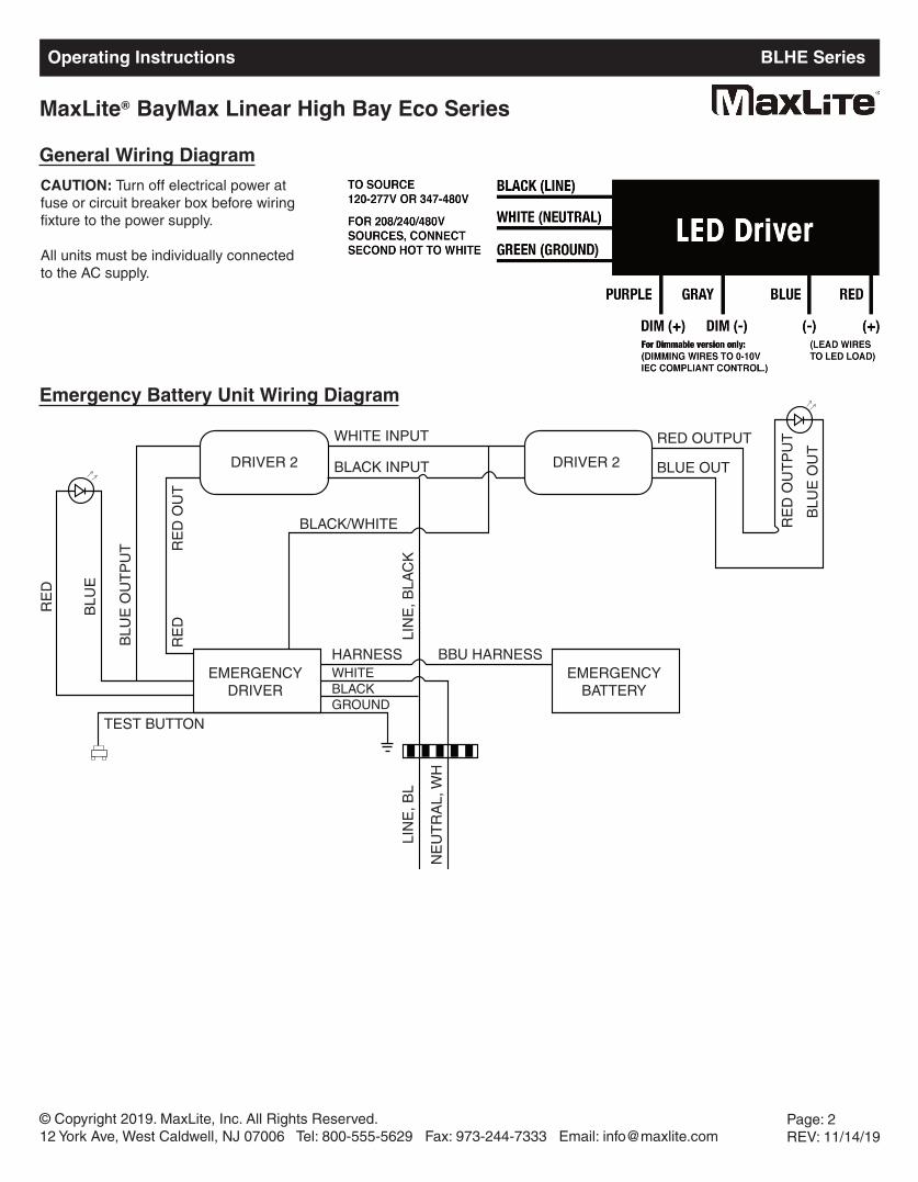
General Wiring DiagramCAUTION: Turn off electrical power at fuse or circuit breaker box before wiring fixture to the power supply.
All units must be individually connected to the AC supply.
© Copyright 2019. MaxLite, Inc. All Rights Reserved.12 York Ave, West Caldwell, NJ 07006 Tel: 800-555-5629 Fax: 973-244-7333 Email: [email protected]
Page: 2REV: 11/14/19
Operating Instructions BLHE Series
MaxLite BayMax Linear High Bay Eco Series®
Emergency Battery Unit Wiring Diagram
RE
D
BLU
E
BLU
E O
UT
PU
T
TEST BUTTON
EMERGENCYDRIVER
EMERGENCYBATTERY
DRIVER 2 DRIVER 2
LIN
E, B
L
NE
UT
RA
L, W
H
RE
DR
ED
OU
T
BLACK/WHITE
LIN
E, B
LAC
K
RED OUTPUT
BLUE OUT
RE
D O
UT
PU
T
BLU
E O
UT
WHITE INPUT
BLACK INPUT
BBU HARNESSHARNESSWHITEBLACKGROUND
Installation & Operation
Disconnect the power by turning off the circuit breaker or by removing the appropriate fuse at the fuse box. Turning the power off using the light switch is not sufficient to prevent electrical shock.1. Remove the new LED fixture from packaging and inspect for any damage. Handle new LED fixture with care.
2. Connect the LED high bay wiring to line wire, black to black, white to white and green to green. Use only UL listed wiring.
3. Clean all residues/fingerprints from the new LED high bay and lens. Double check all hanging hardware before moving onto the next installation.
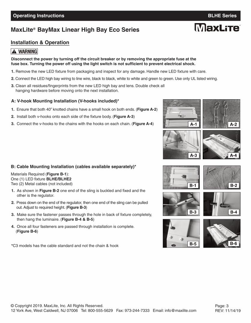
A: V-hook Mounting Installation (V-hooks included)*1. Ensure that both 40” knotted chains have a small hook on both ends. (Figure A-2)
2. Install both v-hooks onto each side of the fixture body. (Figure A-3)
3. Connect the v-hooks to the chains with the hooks on each chain. (Figure A-4)
B: Cable Mounting Installation (cables available separately)*Materials Required (Figure B-1):One (1) LED fixture BLHE/BLHE2Two (2) Metal cables (not included)
1. As shown in Figure B-2 one end of the sling is buckled and fixed and theother is the regulator.
2. Press down on the end of the regulator, then one end of the sling can be pulled out. Adjust to required height. (Figure B-3)
3. Make sure the fastener passes through the hole in back of fixture completely, then hang the luminaire. (Figure B-4 & B-5)
4. Once all four fasteners are passed through installation is complete. (Figure B-6)
*C3 models has the cable standard and not the chain & hook
© Copyright 2019. MaxLite, Inc. All Rights Reserved.12 York Ave, West Caldwell, NJ 07006 Tel: 800-555-5629 Fax: 973-244-7333 Email: [email protected]
Page: 3REV: 11/14/19
Operating Instructions BLHE Series
MaxLite BayMax Linear High Bay Eco Series®
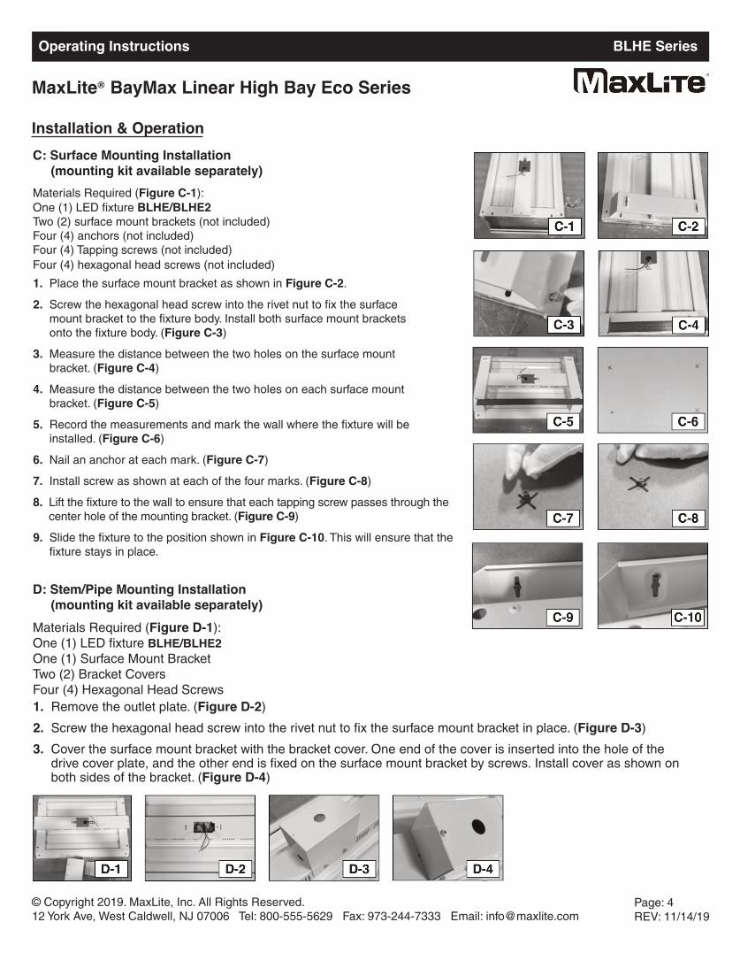
C: Surface Mounting Installation(mounting kit available separately)
Materials Required (Figure C-1):One (1) LED fixture BLHE/BLHE2Two (2) surface mount brackets (not included)Four (4) anchors (not included)Four (4) Tapping screws (not included)Four (4) hexagonal head screws (not included)
Installation & Operation
1. Place the surface mount bracket as shown in Figure C-2.
2. Screw the hexagonal head screw into the rivet nut to fix the surface mount bracket to the fixture body. Install both surface mount brackets onto the fixture body. (Figure C-3)
3. Measure the distance between the two holes on the surface mount bracket. (Figure C-4)
4. Measure the distance between the two holes on each surface mountbracket. (Figure C-5)
5. Record the measurements and mark the wall where the fixture will beinstalled. (Figure C-6)
6. Nail an anchor at each mark. (Figure C-7)
7. Install screw as shown at each of the four marks. (Figure C-8)
8. Lift the fixture to the wall to ensure that each tapping screw passes through the center hole of the mounting bracket. (Figure C-9)
9. Slide the fixture to the position shown in Figure C-10. This will ensure that the fixture stays in place.
D: Stem/Pipe Mounting Installation(mounting kit available separately)
Materials Required (Figure D-1):One (1) LED fixture BLHE/BLHE2One (1) Surface Mount BracketTwo (2) Bracket CoversFour (4) Hexagonal Head Screws1. Remove the outlet plate. (Figure D-2)
2. Screw the hexagonal head screw into the rivet nut to fix the surface mount bracket in place. (Figure D-3)
3. Cover the surface mount bracket with the bracket cover. One end of the cover is inserted into the hole of the drive cover plate, and the other end is fixed on the surface mount bracket by screws. Install cover as shown on both sides of the bracket. (Figure D-4)
© Copyright 2019. MaxLite, Inc. All Rights Reserved.12 York Ave, West Caldwell, NJ 07006 Tel: 800-555-5629 Fax: 973-244-7333 Email: [email protected]
Page: 4REV: 11/14/19
Operating Instructions BLHE Series
MaxLite BayMax Linear High Bay Eco Series®
Operating Instructions BLHE Series
MaxLite BayMax Linear High Bay Eco Series®
© Copyright 2019. MaxLite, Inc. All Rights Reserved.12 York Ave, West Caldwell, NJ 07006 Tel: 800-555-5629 Fax: 973-244-7333 Email: [email protected]
Page: 5REV: 11/14/19
Optional Motion Sensor Settings
Daylight sensor
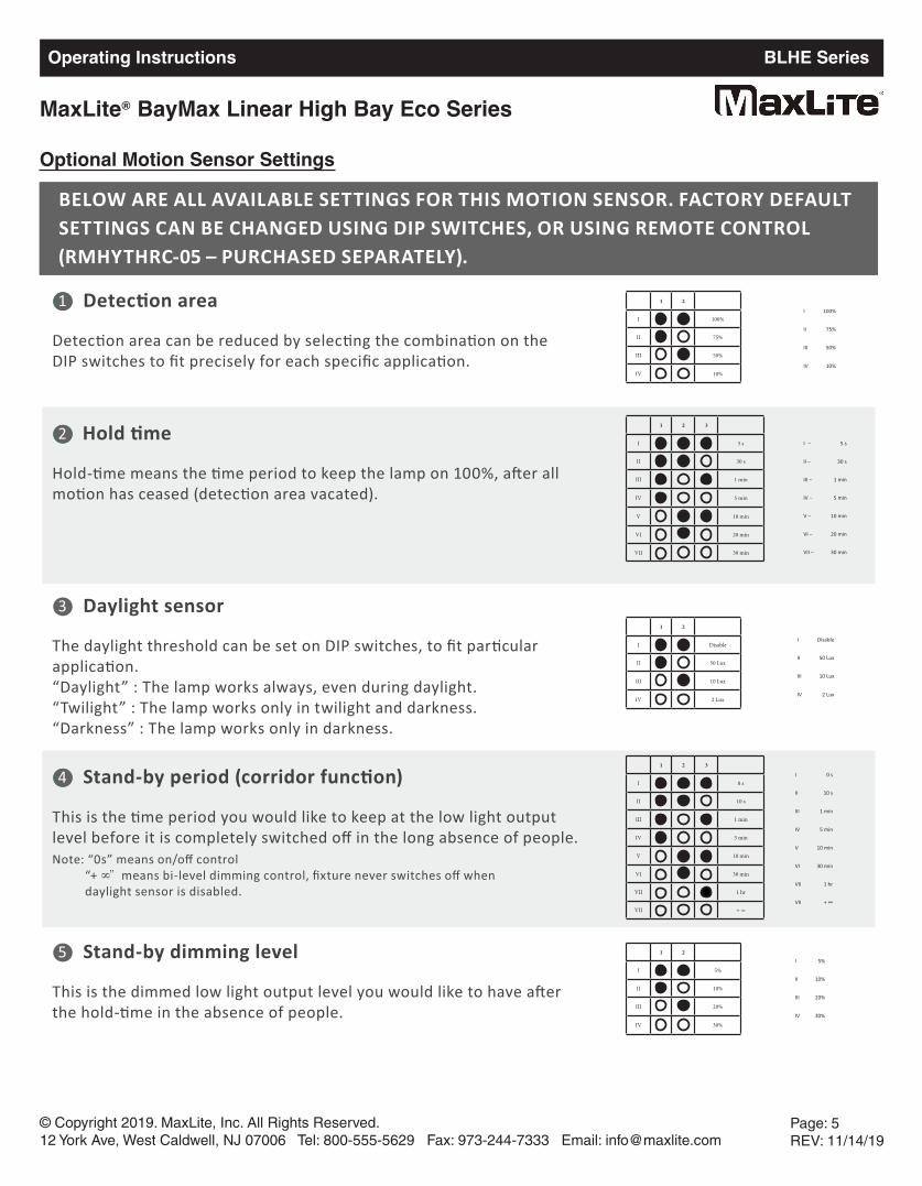
BELOW ARE ALL AVAILABLE SETTINGS FOR THIS MOTION SENSOR. FACTORY DEFAULT SETTINGS CAN BE CHANGED USING DIP SWITCHES, OR USING REMOTE CONTROL (RMHYTHRC-05 – PURCHASED SEPARATELY).
1 2
I 100%
II 75%
III 50%
IV 10%
1 2 3
I 5 s
II 30 s
III 1 min
IV 5 min
V 10 min
VI 20 min
VII 30 min
1 2
I Disable
II 50 Lux
III 10 Lux
IV 2 Lux
1 2 3
I 0 s
II 10 s
III 1 min
IV 5 min
V 10 min
VI 30 min
VII 1 hr
VII + ∞
2
3
5
Detec on area
Detec on area can be reduced by selec ng the combina on on theDIP switches to fit precisely for each specific applica on.
1
Hold me
Hold- me means the me period to keep the lamp on 100%, a!er all mo on has ceased (detec on area vacated).
I – 5 s
II – 30 s
III – 1 min
IV – 5 min
V – 10 min
VI – 20 min
VII – 30 min
The daylight threshold can be set on DIP switches, to fit par cular applica on.“Daylight” : The lamp works always, even during daylight.“Twilight” : The lamp works only in twilight and darkness.“Darkness” : The lamp works only in darkness.
Stand-by period (corridor func on)
This is the me period you would like to keep at the low light output level before it is completely switched off in the long absence of people.Note: “0s” means on/off control “+ ∞” means bi-level dimming control, fixture never switches off when daylight sensor is disabled.
4 I 0 s
II 10 s
III 1 min
IV 5 min
V 10 min
VI 30 min
VII 1 hr
VII + ∞
1 2
I 5%
II 10%
III 20%
IV 30%
Stand-by dimming level
This is the dimmed low light output level you would like to have a!er the hold- me in the absence of people.
I 5%
II 10%
III 20%
IV 30%
I Disable
II 50 Lux
III 10 Lux
IV 2 Lux
I 100%
II 75%
III 50%
IV 10%
Operating Instructions BLHE Series
MaxLite BayMax Linear High Bay Eco Series®
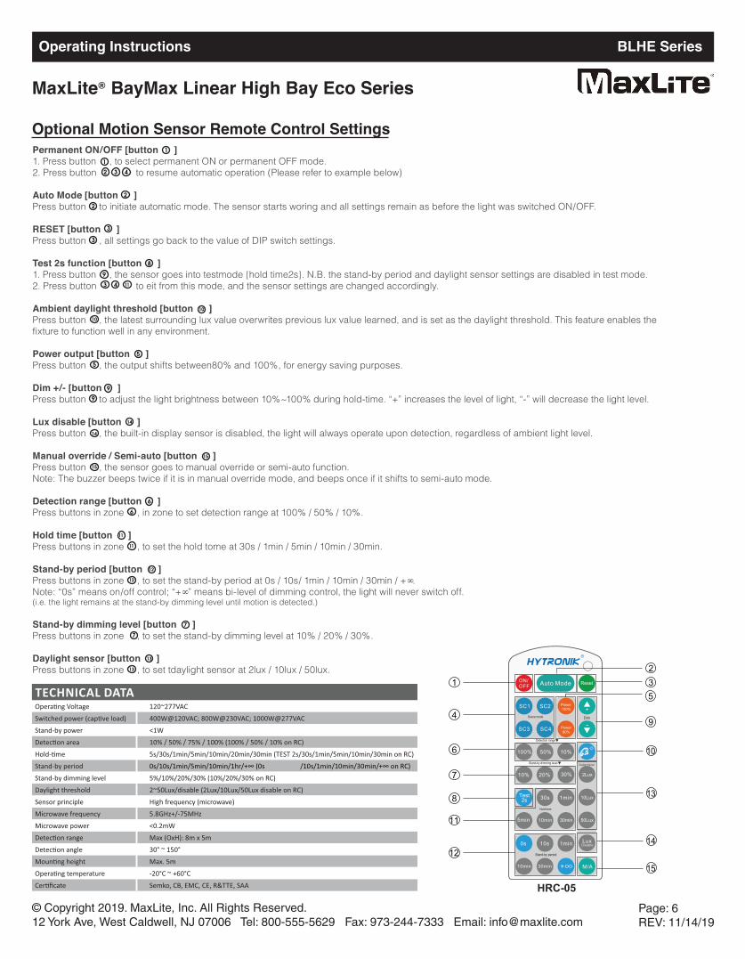
Optional Motion Sensor Remote Control Settings
© Copyright 2019. MaxLite, Inc. All Rights Reserved.12 York Ave, West Caldwell, NJ 07006 Tel: 800-555-5629 Fax: 973-244-7333 Email: [email protected]
Page: 6REV: 11/14/19
2. Press button to eit from this mode, and the sensor settings are changed accordingly.
2. Press button to resume automatic operation (Please refer to example below)
Permanent ON/OFF [button ]1. Press button , to select permanent ON or permanent OFF mode.
Auto Mode [button ]Press button to initiate automatic mode. The sensor starts woring and all settings remain as before the light was switched ON/OFF.
RESET [button ]Press button , all settings go back to the value of DIP switch settings.
Test 2s function [button ]1. Press button , the sensor goes into testmode {hold time2s}. N.B. the stand-by period and daylight sensor settings are disabled in test mode.
Ambient daylight threshold [button ]Press button , the latest surrounding lux value overwrites previous lux value learned, and is set as the daylight threshold. This feature enables thefixture to function well in any environment.
Power output [button ]Press button , the output shifts between80% and 100%, for energy saving purposes.
Dim +/- [button ]Press button to adjust the light brightness between 10%~100% during hold-time. “+” increases the level of light, “-” will decrease the light level.
Lux disable [button ]Press button , the built-in display sensor is disabled, the light will always operate upon detection, regardless of ambient light level.
Manual override / Semi-auto [button ]Press button , the sensor goes to manual override or semi-auto function.Note: The buzzer beeps twice if it is in manual override mode, and beeps once if it shifts to semi-auto mode.
Detection range [button ]Press buttons in zone , in zone to set detection range at 100% / 50% / 10%.
Hold time [button ]Press buttons in zone , to set the hold tome at 30s / 1min / 5min / 10min / 30min.
Stand-by period [button ]Press buttons in zone , to set the stand-by period at 0s / 10s/ 1min / 10min / 30min / +∞.Note: “0s” means on/off control; “+∞” means bi-level of dimming control, the light will never switch off.(i.e. the light remains at the stand-by dimming level until motion is detected.)
Stand-by dimming level [button ]Press buttons in zone , to set the stand-by dimming level at 10% / 20% / 30%.
Daylight sensor [button ]Press buttons in zone , to set tdaylight sensor at 2lux / 10lux / 50lux.
1
1
2 3 4
2
2
3
3
8
9
3 4 11
10
10
5
5
9
9
14
14
15
15
6
6
11
11
12
12
7
7
13
13
5
94
11
12
Stand-by dimming level
Detection range
ON/OFF Auto Mode Reset
Power80%
Test2s
10% 20%
30s 1min
100%
30min10min5min
0s 10s 1min
30%
SC1 SC2
SC3
Scene mode
10min
50% 10%
30min
Hold-time
Stand-by period
5min
LuxDisable
2Lux
10Lux
50Lux
Daylight Sensor
SC4
Power100% +
-Dim
M/A
312
7
8
6 10
13
14
15
HRC-05
TECHNICAL DATA120~277VAC400W@120VAC; 800W@230VAC; 1000W@277VAC
Stand-by power <1W10% / 50% / 75% / 100% (100% / 50% / 10% on RC)5s/30s/1min/5min/10min/20min/30min (TEST 2s/30s/1min/5min/10min/30min on RC)
Stand-by period 0s/10s/1min/5min/10min/1hr/+∞ (0s /10s/1min/10min/30min/+∞ on RC)Stand-by dimming level 5%/10%/20%/30% (10%/20%/30% on RC)Daylight threshold 2~50Lux/disable (2Lux/10Lux/50Lux disable on RC)Sensor principle High frequency (microwave)Microwave frequency 5.8GHz+/-75MHzMicrowave power <0.2mW
Max (OxH): 8m x 5m30° ~ 150°Max. 5m-20°C ~ +60°CSemko, CB, EMC, CE, R&TTE, SAA
© Copyright 2019. MaxLite, Inc. All Rights Reserved.12 York Ave, West Caldwell, NJ 07006 Tel: 800-555-5629 Fax: 973-244-7333 Email: [email protected]
Page: 7REV: 11/14/19
Operating Instructions BLHE Series
MaxLite BayMax Linear High Bay Eco Series®
MaxLite Inc. warrants its products for a minimum period of FIVE (5) years from the earlier of the actual installation dateor 90 days after the original date of purchase from a MaxLite authorized distributor/dealer (the “Warranty Period”), asfollows: If a Product fails to operate during the Warranty Period as a result of defects in materials or workmanship,MaxLite will, at its option, repair it, replace it with the same or like Product.
Please refer to Maxlite’s website (at http://maxlite.com/resources/warranties) for the complete coverage details as wellas the terms and conditions of our warranty. Please note that it is NOT a requirement to register your warranty in orderto initiate a warranty claim unless a Ten Year warranty has been purchased separately, or when applicable and/or purchased separately, your warranty contains a replacement labor allowance.
Limitation of Liability
THIS WARRANTY IS EXCLUSIVE, AND IS THE SOLE REMEDY FOR ANY AND ALL CLAIMS, WHETHER IN CONTRACT, IN TORT OR OTHERWISE ARISING FROM THE FAILURE OF PRODUCT AND IS IN LIEU OF ALLOTHER WARRANTIES, EXPRESS OR IMPLIED, INCLUDING ALL WARRANTIES OF MERCHANTABILITY OR FITNESS FOR A PARTICULAR PURPOSE, WHICH WARRANTIES ARE HEREBY EXPRESSLY DISCLAIMED TOTHE EXTENT PERMITTED BY LAW AND, IN ANY EVENT, SHALL BE LIMITED TO THE WARRANTY PERIODSPECIFIED ABOVE. THE LIABILITY OF MAXLITE SHALL BE LIMITED TO THE TERMS OF THE EXPRESS WARRANTY SET FORTH HEREIN. IN NO EVENT WILL MAXLITE BE LIABLE FOR ANY SPECIAL, INCIDENTAL OR CONSEQUENTIAL DAMAGES INCLUDING, WITHOUT LIMITATION, DAMAGES RESULTING FROM LOSS OFUSE, PROFITS, BUSINESS OR GOODWILL, LABOR COSTS, REMOVAL OR INSTALLATION COSTS, WHETHEROR NOT MAXLITE HAS BEEN ADVISED OF THE POSSIBILITY THEREOF. UNDER NO CIRCUMSTANCES SHALLMAXLITE’S ENTIRE LIABILITY FOR A DEFECTIVE PRODUCT EXCEED THE PURCHASE PRICE OF THAT PRODUCT (EXCLUDING LABOR WARRANTY COVERAGE WHERE SPECIFCALLY OFFERED BY MAXLITE). WARRANTY SERVICES PROVIDED UNDER THESE TERMS AND CONDITIONS DONOT ENSURE THE UNINTERRUPTED OPERATION OF PRODUCTS; MAXLITE SHALL NOT BE LIABLE FOR DAMAGES CAUSED BY ANY DELAYS INVOLVING WARRANTY SERVICE.
This Warranty gives you specific legal rights and you may also have other rights that may vary from state to state. Because some states or jurisdictions do not allow the exclusion or limitation of liability for consequential or incidentaldamages, such limitation may not apply to you.
Warranty Information