Embed Size (px)
Citation preview

An Efficient Defense Scheme
against Selective Forwarding Attack in Wireless Sensor Networks
Thesis submitted in partial fulfillment of the requirements
for the degree of
Master of Technology
Department of Computer Science and Engineering
National Institute of Technology Rourkela
Rourkela, Orissa, 769 008, India
May 2011

An Efficient Defense Scheme
against Selective Forwarding Attack in Wireless Sensor Networks
in
Computer Science and Engineering(Specialization: Information Security)
by
Leela Krishna Bysani
Department of Computer Science and Engineering
National Institute of Technology Rourkela
Rourkela, Orissa, 769 008, India
May 2011

An Efficient Defense Scheme
against Selective Forwarding Attack in Wireless Sensor Networks
Thesis submitted in partial fulfillment of the requirements for the degree of
Master of Technology
in
Computer Science and Engineering(Specialization: Information Security)
by
Leela Krishna Bysani(Roll- 209CS2083 )
Supervisor
Dr.Ashok Kumar Turuk
Department of Computer Science and Engineering
National Institute of Technology Rourkela
Rourkela, Orissa, 769 008, India
May 2011

An Efficient Defense Scheme
against Selective Forwarding Attack in Wireless Sensor Networks
Department of Computer Science and Engineering
National Institute of Technology Rourkela
Rourkela, Orissa, 769 008, India
May 2011

Department of Computer Science and Engineering National Institute of Technology Rourkela Rourkela-769 008, Orissa, India.
Certificate
This is to certify that the work in the thesis entitled An Efficient Defense
Scheme against Selective Forwarding Attack in Wireless Sensor Net-
works by Leela Krishna Bysani is a record of an original research work carried
out by him under my supervision and guidance in partial fulfillment of the require-
ments for the award of the degree of Master of Technology with the specialization
of Information Security in the department of Computer Science and Engineering,
National Institute of Technology Rourkela. Neither this thesis nor any part of it
has been submitted for any degree or academic award elsewhere.
NIT Rourkela Dr. Ashok Kumar Turuk May 2011 Associate Professor, CSE Department
NIT Rourkela, Orissa

Acknowledgment
I am grateful to numerous local and global peers who have contributed towards
shaping this thesis. At the outset, I would like to express my sincere thanks to
Dr.Ashok Kumar Turuk for his advice during my thesis work. As my supervisor, he
has constantly encouraged me to remain focused on achieving my goal. His
observations and comments helped me to establish the overall direction of the re-
search and to move forward with investigation in depth. He has helped me greatly
and been a source of knowledge. I am also thankful to all the professors of the
department for their support.
I am really thankful to my all friends. My sincere thanks to everyone who has
provided me with kind words, a welcome ear, new ideas, useful criticism, or their
invaluable time, I am truly indebted.
I must acknowledge the academic resources that I have got from NIT Rourkela. I
would like to thank administrative and technical staff members of the Depart- ment
who have been kind enough to advise and help in their respective roles.
Last, but not the least, I would like to dedicate this thesis to my family, for
their love, patience, and understanding.
Leela Krishna Bysani
l ee l a k r i s h n a b ys a n i @ g m a i l . c o m

Abstract
Wireless Sensor Networks(WSN) has a wide range of applications in military
and civilian domains. They are more prone to security attacks once deployed, as the
nodes in the network are unattended and unprotected. Conventional security
solutions are infeasible to WSN due to its limited battery and memory constraints.
Selective Forwarding Attack is one among the many security threats in wireless
sensor networks which can degrade network performance. An adversary on the
transmission path selectively drop packet. The adversary same time transfer the
packet, while in few occasions it drops the packet. It is difficult to detect this type
of attack since the packet loss may be due to unreliable wireless communication. In
this thesis, we proposed a defensive mechanism against selective forwarding
attack. The proposed scheme is based on trust value of each node. During data
transmission a node selects a downstream node that has highest trust value, which
is updated dynamically based on the number of packets a node has forwarded and
dropped. We compared our scheme with existing scheme and found that the packet
loss in the proposed scheme is much less than the existing scheme.

Contents
Introduction 2
1.1 Wireless Sensor Network . . . . . . . . . . . . . . . . . . . . . . . . 2
1.2
Problem Definition .
. . . . . . . . . . . . . . . . . . . . . . . . . . 3
1.3
Motivation . . . . . .
. . . . . . . . . . . . . . . . . . . . . . . . . . 3
1.4
Thesis Organization .
. . . . . . . . . . . . . . . . . . . . . . . . . . 4
Certificate
ii Acknowledgement
iii Abstract
iv List of Figures
vii List of Tables
ix
1
Background 6
2.1 Attacks and their Classification . . . . . . . . . . . . . . . . . . . . 7
2.1.1
Selective Forwarding
. . . . . . . . . . . . . . . . . . . . . . 7
2.1.2
Wormhole . . . . . .
. . . . . . . . . . . . . . . . . . . . . . 7
2.1.3
Sybil . . . . . . . . .
. . . . . . . . . . . . . . . . . . . . . . 8
2.1.4 Acknowledgement Spoofing . . . . . . . . . . . . . . . . . . 8
v

2.1.5
Impersonation .
. . . . . . . . . . . . . . . . . . . . . . . . . 8
2.1.6
Eavesdropping .
. . . . . . . . . . . . . . . . . . . . . . . . . 8
2.1.7
Traffic Analysis
. . . . . . . . . . . . . . . . . . . . . . . . . 9
2.2
Selective Forwarding Attack and its classification
. . . . . . . . . . 9
2.3
Countermeasures and Detection Schemes . . . .
. . . . . . . . . . . 11
2.3.1 Detection using acknowledgments . . . .
. . . . . . . . . . . 12
2
v

2.3.2 Lightweight Defense scheme Using Neighbour Nodes as Mon-
itor Nodes . . . . . . . . . . . . . . . . . . . . . . . . . . . . 13
2.3.3 Multi Data Flow Scheme . . . . . . . . . . . . . . . . . . . . 15
2.3.4 Detection Scheme in Hetrogeneous Networks . . . . . . . . . 16
2.3.5 Detection Using Twohop Neighbourhood Information: . . . . 17
Proposed Mechanism 20
3.1
Assumptions: . . . . . . . . . . . . . .
. . . . . . . . . . . . . . . . 20
3.2
Network Construction: . . . . . . . . .
. . . . . . . . . . . . . . . . 21
3.3
Routing Selection based on trust value:
. . . . . . . . . . . . . . . . 23
3.4
Packet Forwarding in presence of attack
. . . . . . . . . . . . . . . 25
3
4 Implementation and Results 28
4.1 Simulation Environment . . .
. . . . . . . . . . . . . . . . . . . . . 28
4.2 Simulation Results . . . . . .
. . . . . . . . . . . . . . . . . . . . . 29
4.2.1 Packet Delivery Ratio . . . . . . . . . . . . . . . . . . . . . 29
4.2.2 Packet Drop Ratio . .
. . . . . . . . . . . . . . . . . . . . . 30
5 Conclusion 35
5.1 Conclusion . . . . . .
. . . . . . . . . . . . . . . . . . . . . . . . . . 35
5.2 Further Development
. . . . . . . . . . . . . . . . . . . . . . . . . . 35
Bibliography 36

List of Figures
2.1 Node B launching selective forwarding attack by dropping a packet 9
2.2 Categorization Of Selective Forwarding Attack based on malicious
node count in network [1]. . . . . . . . . . . . . . . . . . . . . . . . 10
2.3 An example with ACK Span=3 and ACK TTL=6 and u5 as mali-
cious node [2]. . . . . . . . . . . . . . . . . . . . . . . . . . . . . . . 12
2.4 An example where monitor nodes detects an attack and then reroute
the packet [3]. . . . . . . . . . . . . . . . . . . . . . . . . . . . . . . 15
2.5 Dividing original network into two dataflows [1]. . . . . . . . . . . . 16
2.6 Threshold values for detection [4]. . . . . . . . . . . . . . . . . . . . 17
3.1 Hello packet format . . . . . . . . . . . . . . . . . . . . . . . . . . . 21
3.2 Structure Of Neighbor Table . . . . . . . . . . . . . . . . . . . . . . 22
3.3 Example network with 20 nodes deployed in a 4X 5 grid structure . 22
3.4 Network after Construction phase . . . . . . . . . . . . . . . . . . . 23
3.5 Routing Packet Format . . . . . . . . . . . . . . . . . . . . . . . . . 23
3.6 Example to show how the route is selected . . . . . . . . . . . . . . 24
3.7 An Example of packet routing with presence of malicious node . . 26
4.1 Packet Delivery Ratio with malicious nodes varying from zero to two 29
4.2 Packet Delivery Ratio vs Number of Sensor Nodes in presence of
one Malicious Node . . . . . . . . . . . . . . . . . . . . . . . . . . . 29
4.3 Packet Delivery Ratio vs Number of Sensor Nodes in presence of
two Malicious Node . . . . . . . . . . . . . . . . . . . . . . . . . . . 30
4.4 Packet Delivery Ratio vs Number of Malicious Node for a network
of 100 nodes . . . . . . . . . . . . . . . . . . . . . . . . . . . . . . . 30
vii

4.5 Packet Delivery Ratio when malicious nodes are present in different
levels . . . . . . . . . . . . . . . . . . . . . . . . . . . . . . . . . . . 31
4.6 Packet Drop Ratio with malicious nodes varying from zero to two . 31
4.7 Packet Drop Ratio vs Number of Sensor Nodes in presence of one
Malicious Node . . . . . . . . . . . . . . . . . . . . . . . . . . . . . 32
4.8 Packet Drop Ratio vs Number of Sensor Nodes in presence of two
Malicious Node . . . . . . . . . . . . . . . . . . . . . . . . . . . . . 32
4.9 Packet Drop Ratio vs Number of Malicious Nodes for a network of
100 nodes . . . . . . . . . . . . . . . . . . . . . . . . . . . . . . . . 33
4.10 Packet Drop Ratio when malicious nodes are present in different
levels . . . . . . . . . . . . . . . . . . . . . . . . . . . . . . . . . . . 33

List of Tables
4.1 Simulation Parameters . . . . . . . . . . . . . . . . . . . . . . . . . 28
ix

Introduction
Wireless Sensor Network
Problem Definition
Motivation
Thesis Organization

Chapter 1
Introduction
1.1 Wireless Sensor Network
In recent days, WSN are emerging as a promising and interesting area.Wireless
Sensor Network consists of a large number of hetrogeneous/homogeneous nodes
(usually called as sensor nodes) which communicates through wireless medium and
works cooperatively to sense or monitor the environment. The number of sensor
nodes in a network can vary from hundreds to thousands. The nodes senses data
from environment and sends these data cooperatively to the sink/gateway node.
Mostly network is build only for a single application purpose. Mostly WSN are
used for applications such as millitary surveillance and disaster monitoring. Since
its type of applications WSN is mostly deployed in hostile environment where it is
unattended. Coming to the architecture, each sensor node consists of a radio
transciever for communication purpose, micro controller for processing abilities, a
sensor for sensing or monitoring and battery for providing energy. Some of the
popular applications of sensor network are area monitoring, environment moni-
toring(such as pollution monitoring), industrial and machine health monitoring,
waste water monitoring and millitary surviellance.
The characterstics of sensor nodes are as follows. They are
Resource Constraint
Unknown topology before deployment
Unattended and unprotected once deployed
15

1.3 Motivation
Unreliable wireless communication
Due to the above characterstics, WSN are easily vulnerable to attacks. Providing
security solutions to these networks is difficult due to its characterstics such as tiny
in nature and constraints in resources. One of the attacks in WSN, is Selective
Forwarding attack which we are going to explain here.
1.2 Problem Definition
In WSN, sensor nodes use wireless communication to send packets. Due to limited
transmission range, a sensor node uses multi hop transmission to deliver the packet
to a base station. Hence a packet is forwarded through so many nodes to reach the
destination. Sensor networks are usually deployed in hostile environment where an
adversary can compromise some internal nodes which may launch various inside
attacks. One kind of attack caused by malicious nodes is Selective Forwarding. In
Selective Forwarding attack, the compromised internal nodes intentionally drops
some packets passing through them. If node drops all the packets then it becomes
black hole attack. The selective forwarding is difficult to detect since the wireless
communications are not reliable where normally there is a loss of data packets due
to noise. In some cases sensor nodes goes into sleep state to save power, in that
period of time node can not send and receive data. So we have to be careful whether
the packet drop is due to selective forwarding or any other reason.
1.3 Motivation
Monitoring is the main application area of the sensor networks. But, due to
selective forwarding attack the packets are dropped due to which some of the
monitored data is lost. These may degrade the performance of our application.
For example, in millitary battle field; if we lost the data about enemy tanks
arrival, then we would lost the battle. Most of the previous works concentrated on
how to detect the malicious nodes. But, here a multi level secure routing scheme
16

1.3 Motivation
is proposed which would defend the network from the selective forwarding
17

1.4 Thesis Organization
attack. Our motivation for proposing a secure routing is to provide reliable data
transmission to the sink node and at the same time reduce the packet drops by
choosing the nodes with trust value greater than threshold.
1.4 Thesis Organization
The remainder of the thesis is organized as follows. Chapter 2 throws light on
the history of Selective Forwarding Attack and presents the related work done to
mitigate such attacks in WSN.
Chapter 3 describes the proposed mechanism in full detail, that includes Network
Construction, Route Discovery and Packet Forwarding under the attack.
Chapter 4 gives the implementation details of the mechanism, and presents the
results of the implementation with varying parameters.
The work presented is summarized in chapter 5.
18

Background
Attacks and their Classification
Selective Forwarding Attack and its Classification
Countermeasures and Detection Schemes

Chapter 2
Background
Securing WSN is a challenging task because of its characteristics or properties
such as unreliable wireless communication, resource constraints, unknown topol-
ogy prior to deployment, physical tampering of nodes due to unattended and un-
protected environment. To secure them, we have to satisfy security goals. These
security goals can be classified into primary and secondary based on their impor-
tance. The primary security goals are data confidentiality, integrity, availability
and authenticity. The secondary goals which has least importance than primary are
data freshness, self-organization, time synchronization and secure localization.
These primary goals are required based on the application meant for WSN [5]. WSN
are easily prone to security attacks due to its deployment in hostile envi-
ronment. Although, there are many security solutions for traditional networks.
They are not suitable for WSN due to its open space deployment and resource
constraints of memory and energy because of which nodes can not do complex
computations and store large data. So, there is a need of finding new security
measures which will be best suited for the sensor networks. Selective Forwarding
attack is one of the security attack in WSN for which we provide a solution here.
Before discussing about Selective Forwarding attack, we are going to discuss se-
curity threat models and attacks in WSN.
The threat models can be classified in two different ways [6]. One classification is
mote-class attacker and laptop-class attacker. In mote-class type of attack, at-
tacker has same properties as that of node. But, in laptop-class attacker type,
he/she may have access to high energy and more memory by which he can affect
20

2.1 Attacks and their Classification
network more. Coming to the second classification, they are inside attacks and
outside attacks. The security attacks can also be classified based on layer they
attack.
2.1 Attacks and their Classification
The classification of attacks makes us easy to find the threat severity and makes
easy to provide solutions to them. Some of the attacks has been explained below.
They are
2.1.1 Selective Forwarding
In a selective forwarding attack [3, 7], malicious nodes behaves like black hole and
may refuse to forward certain messages and simply drop them, ensuring that they
are not propagated any further. However, such an attacker runs the risks that
neighboring nodes will conclude that she has failed and decide to seek another
route. A more subtle form of this attack is when an adversary selectively forwards
packets. An adversary interested in suppressing or modifying packets originating
from a few selected nodes can reliably forward the remaining traffic and limit
suspicion of her wrongdoing.
2.1.2 Wormhole
In the wormhole attack[1], an adversary tunnels messages received in one part of
the network over a low latency link and replays them in a different part. An
adversary situated close to a base station may be able to completely disrupt routing
by creating a well-placed wormhole. An adversary could convince nodes who would
normally be multiple hops from a base station that they are only one or two hops
away via the wormhole. This can create a sinkhole: since the adversary on the
other side of the wormhole can artificially provide a high-quality route to the base
station, potentially all traffic in the surrounding area will be drawn through her if
alternate routes are significantly less attractive.
21
2.1 Attacks and their Classification
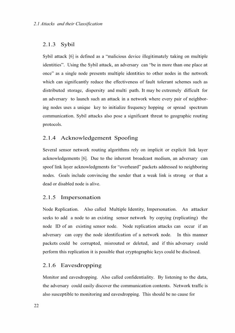
2.1.3 Sybil
Sybil attack [6] is defined as a “malicious device illegitimately taking on multiple
identities”. Using the Sybil attack, an adversary can “be in more than one place at
once” as a single node presents multiple identities to other nodes in the network
which can significantly reduce the effectiveness of fault tolerant schemes such as
distributed storage, dispersity and multi path. It may be extremely difficult for
an adversary to launch such an attack in a network where every pair of neighbor-
ing nodes uses a unique key to initialize frequency hopping or spread spectrum
communication. Sybil attacks also pose a significant threat to geographic routing
protocols.
2.1.4 Acknowledgement Spoofing
Several sensor network routing algorithms rely on implicit or explicit link layer
acknowledgements [6]. Due to the inherent broadcast medium, an adversary can
spoof link layer acknowledgments for “overheard” packets addressed to neighboring
nodes. Goals include convincing the sender that a weak link is strong or that a
dead or disabled node is alive.
2.1.5 Impersonation
Node Replication. Also called Multiple Identity, Impersonation. An attacker
seeks to add a node to an existing sensor network by copying (replicating) the
node ID of an existing sensor node. Node replication attacks can occur if an
adversary can copy the node identification of a network node. In this manner
packets could be corrupted, misrouted or deleted, and if this adversary could
perform this replication it is possible that cryptographic keys could be disclosed.
2.1.6 Eavesdropping
Monitor and eavesdropping. Also called confidentiality. By listening to the data,
the adversary could easily discover the communication contents. Network traffic is
also susceptible to monitoring and eavesdropping. This should be no cause for
22

2.2 Selective Forwarding Attack and its classification
concern given a robust security protocol, but monitoring could lead to attacks
similar to those previously described. It could also lead to wormhole or black hole
attacks.
2.1.7 Traffic Analysis
Traffic analysis attacks are forged where the base station is determinable by ob-
servation that the majority of packets are being routed to one particular node. If
an adversary can compromise the base station then it can render the network
useless
2.2 Selective Forwarding Attack and its classifi- cation
Selective Forwarding Attack is one of the network layer attack described in [6]. In
multi-hop wsn, the nodes send packets to the neighboring nodes thinking that they
forward messages to destination faithfully. In Selective Forwarding attack, mali-
cious or compromised nodes legitimately refuses some packets and drops them. A
packetA B
packet
X CX1 2 3
1 32
Packet Forward
X Packet Drop
23

2.2 Selective Forwarding Attack and its classification
Figure 2.1: Node B launching selective forwarding attack by dropping a packet
24

simple form of this attack is when a malicious node acts like a black hole and drops
all the packets passing through it. However in such an attack, the nodes can easily
detect the attack and can exclude attacker from routing. But, here in selective
forwarding attack, malicious nodes selectively drop/forward packet; which makes
detection of the attack more complicated. Thats why, selective forwarding attack
is known as refined form of black hole attack.
The figure 2.1 explains you how selective forwarding attack occurs. In the figure
2.1, node B is a being compromised by an adversary and it randomly or selectively
drops some of the packets coming from node A; which have to be forwarded to node
C. This is how intruder compromises a node in transmission path and drops some of
the packets selectively. Selective forwarding attacks are typically most effective
when the attacker is explicitly included on the path of a data flow. However, it is
conceivable an adversary overhearing a flow passing through neighboring nodes
might be able to emulate selective forwarding by jamming or causing a collision on
each forwarded packet of interest.
In the fig:2.2 (referred from [1]), we shown how many ways an adversary can de-
(a) Single Malicious Node (b) Two Consecutive Malicious
Nodes
(c) Surrounding Malicious Nodes (d)Non Consecutive Malicious Nodes
Malicious Node Base Station
2525

Figure 2.2: Categorization Of Selective Forwarding Attack based on malicious node count in network [1].
2626

2.3 Countermeasures and Detection Schemes
ploy malicious nodes in transmission path to BS. Fig 2.2(c) shows how all the nodes
surrounding base station are compromised. Note that in this case, base station
does not recieve any message and none of the countermeasures work. Physically
the network has to be redeployed.
Based on its selection in packet drops, selective forwarding can be classified into two
types:
Drops packets of some specified nodes
Drops packets of some specified type
2.3 Countermeasures and Detection Schemes
In this section, we discuss some countermeasures for selective forwarding attack.
Based on the previous research, we can classify mitigation schemes into following
ways
1. Schemes that detect malicious nodes and remove them from routing infor-
mation.
Acknowledgment based detection.
Detection using neighbourhood information.
2. Schemes that uses multi-data flow to mitigate attack.
In latter case, we are not focusing on detecting the attack and malicious nodes, but
just avoiding packet loss using multi data flow. In every detection scheme, there
will be some prior requirements. Before we go through mitigation schemes, let
have a look at some of the requirements and assumptions needed in every
detection process. They are
There must be a secure communication among nodes in the network. In
deployment phase, nodes can not be compromised.
To differentiate an attack from normal dropping of packets due to unreliable
transmission of sensor networks, the drop ratio has to be more than normal.
2727

2.3 Countermeasures and Detection Schemes
2.3.1 Detection using acknowledgments
Yu and Xiao in [2], proposed a scheme which uses a multi-hop acknowledgment
scheme to launch alarms by obtaining responses from intermediate nodes. Each
node in the forwarding path is incharge of detecting malicious nodes. If an in-
termediate node detects a node as malicious in its downstream/upstream, then it
will send an alarm packet to the source node/base station through multi-hops.
Downstream denotes direction towards base station and upstream denotes direc-
tion towards source node. The detection process consists of upstream detection
and downstream detection. The scheme uses three types of packets in transmis-
sion of an event packet and detection of the attack. They are report packet, ACK
packet and alarm packet. There are three different values to be set when a node is
transmitting an event packet. They are ACK Cnt which is a counter value, ACK
Span and ACK TTL which are predefined values.
Figure 2.3: An example with ACK Span=3 and ACK TTL=6 and u5 as malicious node [2].
Upstream Detection Process
When a node detects an event it forwards a report packet to base station through
multi hops. Initially, the field ACK Cnt is set to ACK Span which is a predefined
metric. When each intermediate node receives the report packet, it first saves the
report packet in its cache, decreases the ACK Cnt by one, or resets ACK Cnt to its
initial value ACK Span if ACK Cnt equals to 0 already, and then forwards the
report packet to the next downstream node. Meanwhile, if the node finds ACK
Cnt is equal to 0, it generates an ACK packet, where the TTL in the ACK packet
is initially set to ACK TTL, which is also a pre-defined metric. The node sends the
ACK packet to the upstream node where the previous report packet
2828
2.3 Countermeasures and Detection Schemes
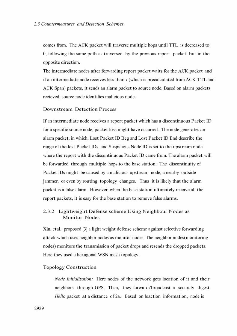
comes from. The ACK packet will traverse multiple hops until TTL is decreased to
0, following the same path as traversed by the previous report packet but in the
opposite direction.
The intermediate nodes after forwarding report packet waits for the ACK packet and
if an intermediate node receives less than t (which is precalculated from ACK TTL and
ACK Span) packets, it sends an alarm packet to source node. Based on alarm packets
recieved, source node identifies malicious node.
Downstream Detection Process
If an intermediate node receives a report packet which has a discontinuous Packet ID
for a specific source node, packet loss might have occurred. The node generates an
alarm packet, in which, Lost Packet ID Beg and Lost Packet ID End describe the
range of the lost Packet IDs, and Suspicious Node ID is set to the upstream node
where the report with the discontinuous Packet ID came from. The alarm packet will
be forwarded through multiple hops to the base station. The discontinuity of
Packet IDs might be caused by a malicious upstream node, a nearby outside
jammer, or even by routing topology changes. Thus it is likely that the alarm
packet is a false alarm. However, when the base station ultimately receive all the
report packets, it is easy for the base station to remove false alarms.
2.3.2 Lightweight Defense scheme Using Neighbour Nodes as Monitor Nodes
Xin, etal. proposed [3] a light weight defense scheme against selective forwarding
attack which uses neighbor nodes as monitor nodes. The neighbor nodes(monitoring
nodes) monitors the transmission of packet drops and resends the dropped packets.
Here they used a hexagonal WSN mesh topology.
Topology Construction
Node Initialization: Here nodes of the network gets location of it and their
neighbors through GPS. Then, they forward/broadcast a securely digest
Hello packet at a distance of 2a. Based on loaction information, node is
2929

2.3 Countermeasures and Detection Schemes
initialized.
Cell Partition: Each node has to determine which RC it belongs to. To
find which RC they belongs to a node first calculates distances from it to
midpoints of four adjacent RCs. Then the RC with minimum distance will be
adopted as its RC by node.
Active Node Election: Now we have to select an active node for each RC to
have communication with other RCs. Active node is the node (x, y) which
satisfies the condition x ≤ x0 andy ≤ y
0 for all x
0 ∈ G and y
0 ∈ G where G is
node coordinate set in RC
Secure Architecture Construction:
In this phase, we construct a secure architecture for secure commmunication be-
tween nodes. Each active node of RCs sends a request packet, the recipient active
node chescks the coordinates of the sent node are right or wrong. If true adds to the
neighbouring RC’s table.
Routing Discovery and Selection:
There are two phases in attack defense scheme, they are finding route & selecting
and data transmission with attack defense. Coming to routing discovery and
selection process, it is designed in a way to defend selective forwarding attack. In
discovery process, we find routes with number of hops in each direction by some
probability schemes.
Data Transmission with Attack Defense:
When an event is generated, a packet is sent by a source node through the selected
route which is generated from the above routing discovery process. During this
transmission if any malicious node in the transmission path drops a packet, then
the monitoring neighbour nodes detects the packet drop and broadcasts an alarm
packet informing that node as malicious. Now one of the monitoring node choses
another path to destination and sends packet without making any delay.
3030

2.3 Countermeasures and Detection Schemes
Figure 2.4: An example where monitor nodes detects an attack and then reroute the packet [3].
2.3.3 Multi Data Flow Scheme
Hung Min-Sun, Chen and Ying-Chu [1] have proposed a single scheme which de-
fends against selective forwarding attack. Their scheme uses multiflow topologies to
defend the attack. In multi-dataflow scheme, the whole network is divided into
different data topologies that makes, a sensor node belonging to one toplogy can
communicate and send information only through nodes of the same topology. This
division can be done at different times. Generally division takes place at
deployment time. If not then the nodes can randomly choose a topology number
after deployment phase.
The condition in this scheme is that every topology has to cover the sensing area
completely. The scheme is well explained in the figure(2). Here the network is
divided into two topologies A and B.
Suppose an event is raised, nodes in both topologies senses the event, raises an
event packet and forwards to the base station. Suppose, a malicious node drops
packet in toplogy A, still packet reaches base station through path in topology
B. By this scheme, it proves that the scheme successfully defend the selective for-
warding attack.
To find the malicious node in this scheme if we have deploye information of sensor
nodes. By using their location information base station can detect malicious node.3131

2.3 Countermeasures and Detection Schemes
Datafl
ow A
Datafl
ow B
Figure 2.5: Dividing original network into two dataflows [1].
2.3.4 Detection Scheme in Hetrogeneous Networks
Brown and Xiaojiang [4] has proposed a scheme to detect selective forwarding
using a Heterogeneous Sensor Network(HSN) model. The HSN consists of powerful
high-end sensors(H-sensors) and large number of low-end sensors(L-sensors). After
deploying sensors, a cluster formation takes place with H-sensor as cluster head.
Detection Process:
Whenever packet drops occur at a node, L-sensor nodes report the packet drop to a
cluster head (an H-sensor). Based on the reports recived, H-sensor runs a test and
determines whether a node is compromised or not.Due to its high memory and
high computational capabilities H-sensor can easily run the test.
The scheme uses a Sequential Probability Ratio Test(SPRT) method. In this
method, we use a random variable X is used to denote status of a packet forward-
ing. X only take values 0 or 1, where 0 denotes a successful packet forwarding and
1 denotes a packet drop. For each node, probability value ’p’ is calculated which is
3232

2.3 Countermeasures and Detection Schemes
equal to the percentage of dropped packets in all forwarded packets at a node. As
shown in the figure, the scheme considers three threshold values p0
, p1
andp2
. If the
node has a value of p below than p1
, then it is considered as legitimate sensor
3333

2.3 Countermeasures and Detection Schemes
Figure 2.6: Threshold values for detection [4].
node and greater than p1
is considered as a compromised node. The other two
thresholds are used to say the behaviour of node with more confidence.
Reporting packet drops and forwarding them:
The report packet format is [dataksequ
]KHu
. Suppose a packet travels from nodes
x,y,z to reach H-sensor then the format will be [[[datakseqx]KHx
kI Dx]KHy
kI Dy
]KHz
.
Here the encryption occurs at L-sensors and after report reaches H-sensor it does
multiple decryption.
2.3.5 Detection Using Twohop Neighbourhood Informa- tion:
Hoang Hai and Eui-Nam Huh [8] proposed a lightweight detection sheme which
uses only neighbourhood information.
Collecting Twohop Neighbourhood information
The scheme uses two hop neighborhood information to detect the attack. In de-
ployment phase, each node constructs two-hop neighbor table. To achieve this,
each node sends/broadcasts a hello packet which contains three important fields
source node ID, intermediate node ID and hop counter value. Initially the source
node and intermediate node ID fields are equal to node ID which broadcasts the
packet and hop counter is initialized to 2. When a node receives hello packet,
checks the hop count value if it is equal to 2 then stores source node ID as its im-
mediate neighbor and changes intermediate node ID with its node ID, decrements
the hop count by 1 and rebroadcasts it. Sensor node receiving this packet will
store intermediate node as their immediate neighbor and source node as two-hop
3434

2.3 Countermeasures and Detection Schemes
neighbor. Here we are assuming that in deployment phase all communications are
secure.
Detection Scheme
Each sensor node associates each neighbor node with malicious counter. If mali-
cious counter crosses the threshold then the node is set as malicious and revoked
from its neighboring list. When a sensor node receives a packet it checks both
source and destination of the packet. If both are in its direct neighbouring list
then it activates monitoring/detection process.
Rule1 The monitor node waits to see if the destination node forwards the
packet on the path to the sink. If not, it raises an alert packet with malicious
factor α to the sender/source node.
Rule2 The monitor node waits and detects the packet which has been for-
warded on the path to the sink. It checks it two-hop neighbour knwoledge to
see if the destination node of the forwarded packet is on the right path to
the sink. If not, it raises an alert packet with malicious factor β to the
sender/source node.
α and β are the malicious factors with 0 < α < 0.5 < β < 1. When a sensor node
recieves an alert packet from its neighbours it calculates the malicious value of the
node and if it crosses threshold value then it revocates it from neighbouring list.
3535

Proposed Mechanism
Assumptions
Network Construction
Routing Selection based On Trust Value
Forwarding Packet in Presence of Attack

Chapter 3
Proposed Mechanism
In this chapter, we proposed an efficient defensive scheme against selective for-
warding attack. The scheme uses a multi level dynamic tree routing for forwarding
the packets to the sink node, where the downstream node is selected based on the
trust value stored in their neighbor table. The nodes which are neighbors to
source and destination act as monitor nodes. These nodes including the source
node monitor the loss of packet. In case of packet drop, source resends the packet
through alternate path. This makes scheme more secure and reliable in presence of
malicious nodes. If the downstream node drops the packet, then the monitoring
nodes reduce the trust value of the downstream node in their neighbor table.
3.1 Assumptions:
We made the following assumptions.
Nodes can not be compromised in the deployment/network construction
phase.
Network is densely populated, i.e, there exist more than one path from a
node to sink.
Transmission links are bidirectional.
Communication between nodes are secured.
3737

3.2 Network Construction:
3.2 Network Construction:
In this section, we discuss the construction of multi level tree. Each node main-
tains its current level which is the number of hops away from the sink node and a
neighbor table which consists of one hop neighbor nodes information. The net- work
construction process begins when a Hello packet is broadcasted by the sink node.
The structure of the H ello packet is as shown in figure 3.1.
Source_ID HopCount NodeLevel
Figure 3.1: Hello packet format
The Source ID refers to the current node which is sending the Hello packet,
NodeLevel refers to current level of the node sending the H ello packet which is
zero for sink node.
The process of network construction is as follows.
Step 1. Sink broadcasts a Hello packet with Source ID field set to its own ID and
NodeLevel to zero.
Step 2. A node on receiving the Hello packet does the following. If the currentLevel
greater than value in N odeLevel + 1
– Set the currentLevel to N odeLevel + 1.
– Update the neighbor table by entering the Source I D in the N eighborI D,
N odeLevel to currentLevel.
– Rebroadcast the H ello packet with N odeLevel set field set to currentLevel,
Source I D set to N ode I D and H opC ount to H opC ount + 1.
If the currentLevel less than or equal to N odeLevel + 1
– Update neighbor table by entering the appropriate fields.
– Discard the H ello packet.
3838

3.2 Network Construction:
Step 3. Repeat Step 2 until all nodes have received H ello packet.
3939

Neighbor_ID NodeLevel Trust Value
1 2 0.
2 1 0.3
3 1 0.6
Figure 3.2: Structure Of Neighbor Table
The structure of the Neighbor Table is shown in figure 3.2. We illustrate the
network construction phase by an example. Consider a network with 20 nodes
which are deployed in a 4x5 grid structure as shown in the figure 3.3. Here S is as a
sink node. In the network construction phase, S broadcast a H ello packet with
N odeLevel field set to zero. One hop neoghbors of S on receive the H ello packet
update the value of their currentLevel and necessary update is done in the neighbor
table. Initially the value of currentLevel at each node is set to infinity. These node
again rebroadcast the H ello packet and the process continues until every node
receives H ello packet. In Figure 3.4 we have shown the neighbor table at node 5
and 18. construction of multilevel tree is shown in Figure 3.4. Neighbor table of a
node maintains the same, higher by 1 and lower by 1 level in the multi level tree.
S
1 2 3 4 5
6 7 8 9 10
11 12 13 14 15
16 17 18 19
20
Figure 3.3: Example network with 20 nodes deployed in a 4X 5 grid structure

3.3 Routing Selection based on trust value:
S Level 0
S 0 0.4 1 0.1
02 0
.9 2 0
.
1 2 3 4 5Level 1
6 7 8 9 10
Level 2
11 12 13 14
15
Level 3
16 17 18 19 20
Level 4
12 3 0.13 3 0.14 3 0.17 40.19
40.
Figure 3.4: Network after Construction phase
3.3 Routing Selection based on trust value:
In this section, we are going to discover the route for forwarding packet in such a
way that it defends the selective forwarding attack. The routing scheme is a
dynamic one. The routing packet format is as shown in figure 3.5.
Source_ID Destination_ID
LastHop_ID
NextHop_ID
Seq_NO
Figure 3.5: Routing Packet Format
The Source ID field refers to the source node for the event packet, lasthop and
nexthop fields refers to the current node holding the event packet and the next
downstream node to which packet will be forwarded. The SeqN o field is set by
the source node using the value currentSeqN o.

3.3 Routing Selection based on trust value:
A node forwards a packet to one of its neighbors that has a lower N odeLevel and
more trust value. If two nodes of the same N odeLevel have same trust value, then
one of them is selected at random.
Let us consider an example shown in Figure 3.6, where node 18 wants to send

Algorithm 1 Routing SelectionInput: isSource, Recieved Routing Packet, currentSeqNO, Neighbor Table(NT)
of node u, γ(threshold value)
Output: Routing Packet
if node u is source node then
Source I D = u
SeqN O = currentSeqN O + 1
end if lasthop = u
Set = {}
for node v in N T do
if currentLevel = v.level + 1 and v.trust >= γ then
Set = Set + v
end if
end for
Randomly choose a node w from Set
S Level 0
1 2 3
6 7
8
11 12 13
4
5
10 9
15
1
4
Level 1
Level 2
Level 3
16 17
1
8 19
20Level 4
12 3 0.13 3 0.14 3 0.17 4 0.19 4 0.
Figure 3.6: Example to show how the route is selected

3.4 Packet Forwarding in presence of attack
data. It selects a node that has greater trust value from nodes 12, 13, 14 which are
in lower node level than that of node 18. In this way, the path to sink node is chosen
from node 18 as shown in Figure 3.6. In the Figure 3.6, the dashed arrow shows the
path selected to sink node.
3.4 Packet Forwarding in presence of attack
We describe below packet forwarding mechanism in the presence of malicious
nodes. The following steps are involved in packet forwarding.
Step 1 Whenever an event occurs, the node generates an event packet.
Step 2 It forwards the packet to the nexthop on the path to the sink and starts a
timer. If the sender can not overhear the transmission from destination, then
it selects another path to the sink.
Step 3 Neighbors of the source, which are in transmission range of destination also
starts a timer on overhearing the transmission from source.
Step 4 Nodes that are monitoring the transmission from the destination decrements
or increments the trust value in the neighbor table.
We maintain a window size w. That is we consider the last w packets for in-
crementing or decrementing the trsut value of a neighbor node. If p number of
packets are dropped in last w packets, then the trust value is decremented by
p/w and incremented by (1 − p/w). In this way trust value of a neigbor node is
updated in neighbor table.
We consider Figure 3.7 to illustrate the transmission in the presence of malicious
nodes. Figure 3.7 shows the transmission in the presence of selective forwarding
attack in level 3. Here node 14 acts as a malicious node that selectively drops the
packet. Assume that the packet from node 18 is dropped at node 14. The source
can not overhear the transmission from 14, so it choose an alternate path
18 − 13 − 8 − 3 to sink. Thus we minimize the impact of malicious node in the
network.

3.4 Packet Forwarding in presence of attack
S Level 0
1 2
3
6 7
8
4 5
9
10
Level 1
Level 2
11 12
16 17
15 1
3 14
12
3 0.1
33 0
.14
3 0.1
7 40.1
94 0
.
1
8 19
20
Level 3
Level 4
Malicious Node
Figure 3.7: An Example of packet routing with presence of malicious node

Implementation and Results
Simulation Model and Environment
Results

Chapter 4
Implementation and Results
In this chapter, we discuss the simulation and results of the simulation. We simu-
lated the proposed method using Castalia Simulator which runs in OMNET++.
4.1 Simulation Environment
For simulation, we have selected Castalia simulator.The number of nodes is varied
between 10 to 50 and are randomly deployed in an area of 150 x 150 square meters.
Simulation time is 600 seconds. Simulation parameters are shown in the Table 4.1.
Parameters considered for simulation are taken from Telosb mote. The metrics
we considered for comparison are he packet delivery ratio and packet drop ratio in
presence and absence of malicious node and compared with and without the
proposed scheme.
Simulation Area 150 x 150 square metresNo. Of Nodes n
Simulation Duration 600 secondsData Rate 250Kb
psNoise Bandwidth 194 KHzRx Power 62mWTx Power 62mWsleep Power 1.4mW
Table 4.1: Simulation Parameters
4747

4.2 Simulation Results
4.2 Simulation Results
4.2.1 Packet Delivery Ratio
It is observed from the Figures 4.1, 4.2, 4.3, 4.4, 4.5 that the packet delivery ratio in
the presence of malicious node is higher on the proposed scheme. This is due to the
fact that in the proposed scheme a node selects a trusted downstream to deliver a
packet to the sink node. In case of a packet loss it retransmit to the next most
trusted download link.
100
Packet Delivery Ratio vs Number of Sensor Nodes
zero malicious node one malicous node
two malicous nodes
95
Packet Delivery Ratio(%)
90
85
80
75
7010 15 20 25 30 35 40 45 50
Number of Sensor Nodes
Figure 4.1: Packet Delivery Ratio with malicious nodes varying from zero to two
100
Packet Delivery Ratio in presence of one Malicious Node
with scheme without scheme
90
Packet Delivery Ratio(%)
80
70
60
5010 15 20 25 30 35 40 45 50
Number of Sensor Nodes
Figure 4.2: Packet Delivery Ratio vs Number of Sensor Nodes in presence of oneMalicious Node
4848

100
Packet Delivery Ratio in presence of Two Malicious Node
with scheme without scheme
90
Packet Delivery Ratio(%)
80
70
60
5010 15 20 25 30 35 40 45 50
Number of Sensor Nodes
Figure 4.3: Packet Delivery Ratio vs Number of Sensor Nodes in presence of twoMalicious Node
Packet Delivery Ratio in presence of attack
85
80
with scheme without scheme
75
Packet Delivery Ratio(%)
70
65
60
55
50
45
40
350 5 10 15 20 25 30 35 40 45 50
Number of Malicious Nodes
Figure 4.4: Packet Delivery Ratio vs Number of Malicious Node for a network of100 nodes
4.2.2 Packet Drop Ratio
It is seen from the Figures 4.6, 4.7, 4.8, 4.9, 4.10 the packet drop ratio in the
proposed scheme is less in the presence of malicious nodes. With increase in the
number of malicious nodes, the packet drio ratio increases. This is an expected
result.
4949

100
95
Packet Delivery Ratio under attack in different levels
Level 1Level 2Level 3Level 4
Packet Delivery Ratio(%)
90
85
80
75
701 1.5 2 2.5 3 3.5 4 4.5 5
Number of Malicious Nodes(%)
Figure 4.5: Packet Delivery Ratio when malicious nodes are present in different levels
0.08
0.07
Packet Drop Ratiozero malicious node one malicious node two malicious node
0.06
Packet Drop Ratio
0.05
0.04
0.03
0.02
0.01
010 15 20 25 30 35 40 45 50
Number of Sensor Nodes
Figure 4.6: Packet Drop Ratio with malicious nodes varying from zero to two

0.11
0.1
Packet Drop Ratio in presence of one malicious node
with scheme without scheme
0.09
0.08
Packet Drop Ratio0.07
0.06
0.05
0.04
0.03
0.02
0.01
010 15 20 25 30 35 40 45 50
Number of Sensor Nodes
Figure 4.7: Packet Drop Ratio vs Number of Sensor Nodes in presence of oneMalicious Node
0.12
Packet Drop Ratio in presence of two malicious node
with scheme without scheme
0.1
0.08
Packet Drop Ratio
0.06
0.04
0.02
010 15 20 25 30 35 40 45 50
Number of Sensor Nodes
Figure 4.8: Packet Drop Ratio vs Number of Sensor Nodes in presence of twoMalicious Node

0.5
Packet Drop Ratio in presence of attack
0.45
0.4
0.35
0.3
Packet Drop Ratio
0.25
0.2
0.15
0.1
0.05
with scheme without scheme
0 5 10 15 20 25 30 35 40 45 50
Number of Malicious Nodes
Figure 4.9: Packet Drop Ratio vs Number of Malicious Nodes for a network of100 nodes
0.2
0.18
Packet Drop Ratio under attack in different levels
Level 1Level 2Level 3Level 4
0.16
0.14
Packet Drop Ratio
0.12
0.1
0.08
0.06
0.04
0.02 1 1.5 2 2.5 3 3.5 4 4.5 5
Number of Malicious Nodes(%)
Figure 4.10: Packet Drop Ratio when malicious nodes are present in different levels

Conclusion
Further Development

Chapter 5
Conclusion
5.1 Conclusion
A new multi level secure routing scheme has been proposed which defense the
sensor network from the attack. The routing scheme is a reactive one, which
dynamically finds the path and sends the packet. Due to this, the adversary can
not know in advance which node to compromise. Due to the concept of trust value,
the packet reliability increases. This reduces node to choose a compromised node
till it finds the presence of attack. Our scheme is effectively defends the attack
and also provides reliable data transmission to the sink node using resending
mechanism.
The scheme has been evaluated using the simulator and results are compared under
attack with and without the scheme. The results show a significant increase in
throughput and decrease in packet drop ratio. Thus, the system has successfully
defend the attack and provide a reliable transmission to the sink node.
5.2 Further Development
In reality, WSN links are not symmetric. So, in the future we can provide system to
improve the scheme to work for a network with asymmetric links. Our scheme is
just defending the attack but not finding the malicious node. In future, we can find
a solution on how to find the malicious node and how optimally and reliably we can
alert the neighbor nodes about the malicious node.
5454

Bibliography
[1] Hung-Min Sun, Chien-Ming Chen, and Ying-Chu Hsiao. Un-
mask: Utilizing neighbor monitoring for attack mitigation in mul-
tihop wireless sensor networks. volume 8, pages 148–164, 2010.
h tt p : // d x . d oi . o r g / 10 . 1016 / j.adhoc.2009.06.002.
[2] Bo Yu and Bin Xiao. Detecting selective forwarding attacks in wireless sensor
networks. In Parallel and Distributed Processing Symposium, 2006. IPDPS
2006. 20th International, page 8 pp., 2006.
[3] Wang Xin-sheng, Zhan Yong-zhao, Xiong Shu-ming, and Wang Liang-min.
Lightweight defense scheme against selective forwarding attacks in wireless
sensor networks. pages 226–232, oct. 2009.
[4] Jeremy Brown and Xiaojiang Du. Detection of selective forwarding at-
tacks in heterogeneous sensor networks. In ICC, pages 1583–1587, 2008.
h tt p : // d x . d oi . o r g / 10 . 1109 / ICC.2008.306.
[5] G. Padmavathi and D. Shanmugapriya. A survey of attacks, security mech-
anisms and challenges in wireless sensor networks. CoRR, abs/0909.0576,
2009. h tt p : // a r x i v . o r g / a b s / 0909 . 0576 .
[6] Chris Karlof and David Wagner. Secure routing in wireless sensor net-
works: attacks and countermeasures. Ad Hoc Networks, 1(2-3):293–315, 2003.
h tt p : // d x . d oi . o r g / 10 . 1016 / S1570-8705(03)00008-8.
[7] S. Kaplantzis, A. Shilton, N. Mani, and Y.A. Sekercioglu. Detecting selective
forwarding attacks in wireless sensor networks using support vector machines.
5555
Bibliography
In Intelligent Sensors, Sensor Networks and Information, 2007. ISSNIP 2007.
3rd International Conference on, pages 335–340, 2007.
[8] Tran Hoang Hai and Eui nam Huh. Detecting selective forwarding attacks in
wireless sensor networks using two-hops neighbor knowledge. In NCA, pages
325–331, 2008. h tt p : // d oi . ieeeco m pu t e r s ocie t y . o r g / 10 . 1109 / NCA.2008.13.
[9] Tanveer Zia and Albert Y. Zomaya. Security issues in wireless sensor net-
works. In ICSNC, page 40, 2006.
[10] Bin Xiao, Bo Yu, and Chuanshan Gao. Chemas: Identify suspect nodes in
selective forwarding attacks. J. Parallel Distrib. Comput., 67(11):1218–1230,
2007. h tt p : // d x . d oi . o r g / 10 . 1016 / j.jpdc.2007.04.014.
[11] Hemanta Kumar Kalita and Avijit Kar. Wireless sensor network security
analysis. In International Journal of Next-Generation Networks, 2009.
[12] Issa Khalil, Saurabh Bagchi, Cristina Nita-Rotaru, and Ness B. Shroff.
Unmask: Utilizing neighbor monitoring for attack mitigation in multi-
hop wireless sensor networks. Ad Hoc Networks, 8(2):148–164, 2010.
h tt p : // d x . d oi . o r g / 10 . 1016 / j.adhoc.2009.06.002.
[13] Young Ki Kim, Hwaseong Lee, Kwantae Cho, and Dong Hoon Lee. Cade:
Cumulative acknowledgement based detection of selective forwarding attacks
in wireless sensor networks. In Convergence and Hybrid Information Technol-
ogy, 2008. ICCIT ’08. Third International Conference on, volume 2, pages
416–422, nov. 2008.
[14] An efficient countermeasure to the selective forwarding attack in wireless
sensor networks. TENCON 2007 - 2007 IEEE Region 10 Conference, pages
1–4, oct. 2007.
[15] Alec Woo, Terence Tong, and David Culler. Taming the underlying challenges of
reliable multihop routing in sensor networks. In Proceedings of the 1st
international conference on Embedded networked sensor systems, SenSys ’03,
5656

Bibliography
pages 14–27, New York, NY, USA, 2003. ACM.
5757

Bibliography
[16] h tt p :// ca s t a li a . np c . n i c t a . c o m . a u / .
[17] Hung cuong Le, Herve Guyennet, and Noureddine Zerhouni. Over-hearing
for energy efficient in event-driven wireless sensor network. IEEE Interna-
tional Conference on Mobile Adhoc and Sensor Systems Conference, 0:633–
638, 2006.
5858