Embed Size (px)
Citation preview
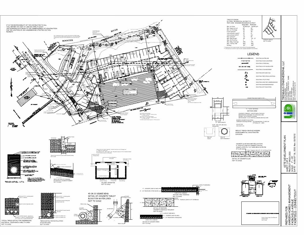
EXISTING WATER LINE
EXISTING CHAIN LINK FENCE
EXISTING STONE WALL
EXISTING CATCH BASIN & PIPE
EXISTING STOCKADE FENCE
EXISTING WETLAND FLAG
EXISTING TREE (FIELD LOCATION)
EXISTING UTILITY POLE
EXISTING SANITARY SEWER MANHOLE
EXISTING DRAINAGE MANHOLE
EXISTING SPOT ELEVATION
LEGEND
FA
IRC
HIL
D A
VE
NU
E
RIVER
ROOSTER
SAN MHTF=10.99CENTERLINE INV=1.39
SAN MHTF=13.76CENTERLINE INV=3.17
SAN MHTF=15.41CENTERLINE INV=3.59
SAN MHTF=9.22CENTERLINE INV=4.50
CBTF=9.77INV 15"(NW)=5.45
CBTF=10.95
STORM MHTF=10.71
STORM MHTF=11.10
STORM MHTF=10.93CENTERLINE INV=2.60
PROPOSED APARTMENT BUILDING
THREE STORIES
FIRST FLOOR = 18.0'
FOOTPRINT = 10,864 SQUARE FEET
16.00fg
16.00fg
16.00fg
15.00fg
15.00fg
15.00fg
15.00fg
16.00fg
16.00fg
15.00fg
15.00fg
15.40fg
15.60fg
15.40fg
15.60fg
15.40fg
15.60fg
15.60fg
16.00fg
13.20fg
15.60fg
11.00fg
12.00fg
10.80fg
12.50fg
15.60fg
14.50fg
High point & Limit of
Permeable Pavement
This area shall be standard
dense mix bituminous
concrete
Surface of this portion of parking
facility shall be permeable pavement
See detail
Proposed Finish Grade
Spot Elevation (typ)
3' Wide Trench Drain across
driveway
New CB
Rim = 12.00'
Invs. in & out = 8.50'
33 lf - 12" HDPE pipe
S = 0.013 ft/ft
Inv. of 12" HDPE
= 8.0'
s.s
PVC roof drain t
o
permeable pave
ment
PVC roof drain to permeable pavement
Regrade area as shown to provide
compensating storage in flood
way (4,078 cubic feet)
N79°44'29"E
260.41'
S38°20'10"E
235.29'
L = 322 . 70 '
R= 2441 . 83
N47°29'4
7"E
60.91'
N89°53'46"W
179.87'
N89°53'46"W
186.26'
N72°29'33"E
81.02'
N72°29'33"E
81.38'
N86°06'08"E
82.51'
Proposed Underground
Utilities
Closing line for surveyors
Proposed sanitary sewer lateral
min. pitch of 1/4" per foot
Proposed 2" water service
line
Water Quality Volume (Building)
WQV = 1"(A)/12 = 1" (0.267)/12 = 0.0223 acre-feet
or ( 970.66 cubic feet)
Water Quality Volume (Parking/sidewalks)
WQV = 1"(A)/12 = 1" (0.483)/12 = 0.0403 acre-feet
or ( 1,753.3 cubic feet)
Total Water Quality Volume (required) = 2,723.96 cubic feet
Note: Compensating storage is to replace flood storage within FEMA Floodway
that will be lost due to slight grading of parking facility. Area filled within FEMA
Floodway affects 3,930 cubic feet and compensating area provides 4,087 cubic
feet.
Three Foot Wide
Stone dust path
Thr
ee F
oot
Wid
e
Sto
ne d
ust
path
Underdrain for Permeable Pavement - Connect to
Trench Drain Outlet
Sol
id 6
" PV
C Pi
pe (A
STM
D30
34, S
dr. 3
5)
S =
0.0
ft/
ft
Inv. in = 12.58'
1000 GALLON
OIL/GRIT
SEPARATOR
See Detail
7 lf - 12" HDPE pipe
S = 0.01 ft/ft
Inv. = 8.43'Inv. = 8.43'
Raise MH rim to match
finish grade
B - 2
B - 1
Approximate Location of
test boring - see report
for more information
20' Wide PVC Grass
Pavers for fire access
20' Wide PVC Grass
Pavers for fire access
Concrete Apron
Back flow valve on
lateral line -
accessible from
finish grade
Note: All curbing and sidewalks
shall be concrete - see details
Concrete pad for dumpsters -
Enclose with wood privacy
fence - pitch pad to
driveway
6 cu.yd garbage dumpster
1 cu.yd recycle dumpster
Stream Channel Lines
State of Connecticut
Rooster River
Taken from TC Map #3078
Fairfield Land Records
18" ACCMP
Handicap
Sign (typ)
Handicap
Sign (typ)
Note: Elevation of dumpster pad = 15.80'
wat
wat
wat
wat
wat
wat
gas
gas
gas
gas
gas
gas
gas
gas
gas
elec
elec
elec
elec
elec
elec
tele
tele
tele
tele
tele
tele
cbl
cbl
cbl
cbl
cbl
cbl
IT IS THE RESPONSIBILITY OF THE CONTRACTOR TO CALL"CALL-BEFORE-YOU-DIG" AT 1-800-922-4455 AT LEASTTWO WORKING DAYS PRIOR TO THE COMMENCEMENT OF CONSTRUCTIONFOR THE LOCATION OF ANY UNDERGROUND UTILITIES ON THISPROPERTY.
TABLE OF ZONING
EX. ZONE: RESIDENTIAL DISTRICT "B"
REQUIRED PROPOSED
Min. Lot Area 43,560 sq.ft. 65,106 sq.ft.
Min. Square on Lot 60' 60'
Min. Lot Frontage 50' 207'
Front setback* 10' 49'
Side setback (left)* 10' 116'
Rear setback* 10' 78'
Max. Bldg Height 40' 39' - 11"
Max. # of stories 3 3
Max. Bldg. Coverage 20% 17%
Side setback (right)* 10' 13' Fairchild
Avenue
Bradf
ord
Stree
t
Dresde
n
Street
Nathan HaleStreet
Berwick
Avenue
Brentwood
AvenueHalleyAvenue
King
s H
ighw
ay E
ast
Site
VICINITY SKETCH
NOT TO SCALE
SECTION THRU SIDEWALK
NOT TO SCALE
COMPACTED SUBGRADE
8" - 3/4" PROCESSED STONE (BASE)
LAYER OF WIRE MESH
5" - CONCRETE (3000 PSI MIX)
NOT TO SCALE
DETAIL OF PROPOSED
TOWELED JOINTS AT 5' INTERVALS
4' WIDE
CONCRETE SIDEWALK/ WALKWAY
6" R=2"
12"
6"
8"
Cast In-place concrete
curb
Permeable Pavement
12" - 3/4" PROCESSED STONE (BASE)
6" - CONCRETE (3000 PSI MIX)
LAYER OF WIRE MESH
COMPACTED SUBGRADE
SECTION OF CONCRETE APRON
NOT TO SCALE
PROP. ZONE: DESIGNED RESIDENCE DISTRICT
Max. TOTAL FAR 50% 50%
Parking 81* 68**
* 1.5 spaces per unit required under Section 28.6.1 of the zoning regulations
** 1.25 spaces per bedroom required under proposed amendment to Section 28.6.1
FITTING
TYPICAL
TRENCH WALL
THRUST BLOCK
CONCRETE
18"
45 DEGREES
NOT TO SCALE
BLOCK FOR WATER LINES
DETAIL OF CONCRETE THRUST
WATER MAIN
TRENCH WALL
THRUST BLOK
CONCRETE
36"12"
45 OR 22 DEGREE BEND
Not to Scale
Typical Cross section of Cast In-place Concrete Curbing
See Site Plan
Finish Grade -
Concrete Curb
Edge
1" Radius Tooled
Pavement
Permeable
6"2"
5"
8"
16"
NOT TO SCALE
OF WATER LINES
TRENCH DETAIL FOR INSTALLATION
than 6" in diameter
Clean earth fill: no stones greater
6" dead sand
Bed and Backfill water lines with
2"
and top of water line
42" Minimum between finish grade
4" Ductile Iron Water Line
2" Ductile Iron Water Line
NOT TO SCALE
DETAIL OF CONCRETE SLAB
Note: Dumpster slab is 10' x 8' with Broom FinishOF SLAB
SINGLE LAYER OF 6" X 6" WIRE MESH IN CENTER
6" THICK OF 3,000 PSI CONCRETE, INSTALL
CONCRETE SLAB FOR DUMPSTER LOCATION
Clean earth fill: no stones greater
than 6" in diameter
2"
4"
Finish grade
conduit
Install magnetic location tape above center
fill 4" above top of conduit with dead sand
minimum of 1"; Bed on 2" dead sand and back-
3 - 4" Sch. 40 PVC Conduits - separate by a
NOT TO SCALE
ELECTRICAL, TELEPHONE & CABLE TV LINES
TYPICAL TRENCH DETAIL FOR UNDERGROUND
20
3-2
64
-45
59 (
fax)
20
3-2
64
-4558
SO
UT
HB
UR
Y, CO
NN
EC
TIC
UT
0
6488
114
HU
NT
ER
S R
IDG
E R
OA
DC
IVIL
EN
GIN
EE
RS
TR
IN
KA
US
EN
GIN
EE
RIN
G, LL
C
ww
w.t
rink
ause
ngin
eeri
ng.c
omE
mai
l:
stri
nkau
s@ea
rthlin
k.ne
t
FA
IR
FIE
LD -
CO
NN
EC
TIC
UT
PRE
PAR
ED
FO
R
FA
IR
CH
ILD
AV
EN
UE
GA
RD
EN
HO
ME
S M
AN
AG
EM
EN
T
DA
TE
: A
UG
US
T 1
6,
20
11; R
ev. 1
0/1
0/1
1S
CA
LE:
1"
= 2
0'
PRO
JE
CT
#0
23-2
011
SH
EE
T 1
OF 4
SIT
E D
EV
ELO
PME
NT
PLA
N
NOT TO SCALE
BITUMINOUS CONCRETE PAVEMENT
CROSS SECTION OF STANDARD
CONCRETE CURB - SEE DETAIL ON SHEET 1
1-1/2" BITUMINOUS CONCRETE (BASE COURSE)1-1/2" BITUMINOUS CONCRETE (FINISH COURSE)
GRADE PER SITE PLAN
2" - 3/4" PROCESSED GRAVEL BASE
10" - 1-1/4" PROCESSED GRAVEL BASE
COMPACTED SUBGRADE
Provide minimum capacity of 1,000 gallons
Min. Capacity of unit = 400 * 0.065 * 7.48 = 180 gallons capacity for First & Sediment Chamber
A = 2,855 sq.ft. (0.065 acres)
Sizing Criteria for Oil/Grit Separator: 400 cubic feet per acre of drainage area.
NOT TO SCALE
OIL/GRIT SEPARATOR
(flow buffering)
Third Chamber
catch basin
Outlet pipe to existing
regulates water level
Inverted Elbow pipes
Orifices ( 2 - 4" PVC pipes)
(oil separating)
Second Chamber
(sediment trapping)
First Chamber
Accumulated Sediment
finish grade
Access Manholes to
drainage system
Inlet from storm
Not to Scale
Hooded Outlet
Detail of Deep Sump Catch Basin with
www.modern.com
610-847-5112
OTTSVILLE, PA 18942CORPORATE HEADQUARTERS: 210 DURHAM ROAD, P.O. BOX 339
MODERN CONCRETE SOLUTIONS
GRATE DESIGN: HS-25 TRAFFIC LOADING, BICYCLE SAFE
DESIGN: HS-25 TRAFFIC LOADINGREINFORCING CONFORMS TO ASTM A615 & A185
CONCRETE STRENGTH: 4000 PSI MIN AT 28 DAYS
SECTION VIEW
5', 7' OR 10' SECTIONS
CONNECTING ROD POCKETS (TYP)
"D" = GRATE WIDTH
END VIEW
7"
DIVISION
ENVRIONMENTAL & WASTEWATER
PRECAST TRENCH DRAIN BY MODERN
WITH KNOCKOUT
END CAP
SOLID
END CAP
SEPARATELY
NOTE: END CAPS ARE SOLD
2"
7"26"
24"
30-3/4"
27-1/4"
40"
FA
IRC
HIL
D A
VE
NU
E
RIVER
ROOSTER
SAN MHTF=10.99CENTERLINE INV=1.39
SAN MHTF=13.76CENTERLINE INV=3.17
SAN MHTF=15.41CENTERLINE INV=3.59
SAN MHTF=9.22CENTERLINE INV=4.50
CBTF=9.77INV 15"(NW)=5.45
CBTF=10.95
STORM MHTF=10.71
STORM MHTF=11.10
STORM MHTF=10.93CENTERLINE INV=2.60
PROPOSED APARTMENT BUILDING
THREE STORIES
FIRST FLOOR = 18.0'
FOOTPRINT = 10,864 SQUARE FEET
PVC roof drain t
o
permeable pave
ment
PVC roof drain to permeable pavement
Regrade area as shown to provide
compensating storage in flood
way (4,078 cubic feet)
N79°44'29"E
260.41'
S38°20'10"E
235.29'
L = 322 . 70 '
R= 2441 . 83
N47°29'4
7"E
60.91'
N89°53'46"W
179.87'
N89°53'46"W
186.26'
N72°29'33"E
81.02'
N72°29'33"E
81.38'
N86°06'08"E
82.51'
Note: Compensating storage is to replace flood storage within FEMA Floodway
that will be lost due to slight grading of parking facility. Area filled within FEMA
Floodway affects 3,930 cubic feet and compensating area provides 4,087 cubic
feet.
Three Foot Wide
Stone dust path
Thr
ee F
oot
Wid
e
Sto
ne d
ust
path
sf
sf
sf
sf
sf
sf
sf
sf
sf
sf
sf
sf
sf
sf
sf
sf
sf
sf
sf
sf
sf
sf
sf
TEMPORARY SOIL STOCKPILE -
SURROUND WITH SILTATION
FENCE BARRIER
Siltation Fence Barrier
See Detail
50' Construction Entrance
See Detail
Siltation Fence Barrier
See Detail
Siltation Fence Barrier
See Detail
"A"
"A"
5 Mountain
Laurel
2 Gallon Container
7 Boxwood
2 Gallon Container
4 Oakleaf Hydranga
2 Gallon Container
5 Mountain
Laurel
2 Gallon Container
2" Cal. Pin Oak
Raise MH rim to match
finish grade
B - 2
B - 1
Approximate Location of
test boring - see report
for more information
Bench
PICNIC TABLE
8 - Emerald Green Arborvitae
(1.5" caliper) along northwest
property line at 6'+ on center
& in slightly staggered alignment
NS
CAL
5 VD
6 KL
9 SL
CF
3 JV
CF
JV
ACCF
CAL
NS
NS
REMOVE INVASIVE PLANTS
PER BIOLOGIST
SEED WITH
ECOLOGICAL SEED
MIX
SEED WITH NEW ENGLAND
WILDFLOWER MIX AND
INSTALL WILDFLOWERS
INSTALL ECOLOGICAL LAWN
SEED MIX ALONG THE
PERIMETER
BUTTERFLY WILDFLOWER
MEADOW
9 SL 8 SL
SEED WITH NEW ENGLAND
WILDFLOWER MIX &
INSTALL WILDFLOWERS
AR
6 KL
AR
BUTTERFLY WILDFLOWER
MEADOW
Bench
CF
4 Oakleaf Hydranga
2 Gallon Container
BUTTERFLY WILDFLOWER
MEADOW
20' Wide PVC Grass
Pavers for fire access
20' Wide PVC Grass
Pavers for fire access
Concrete Apron
Note: All curbing and sidewalks
shall be concrete - see details
Concrete pad for dumpsters -
Enclose with wood privacy
fence - pitch pad to
driveway
6 cu.yd garbage dumpster
1 cu.yd recycle dumpster
Stream Channel Lines
State of Connecticut
Rooster River
Taken from TC Map #3078
Fairfield Land Records
18" ACCMP
Handicap
Sign (typ)
Handicap
Sign (typ)
3 - Qp
Note: Elevation of dumpster pad = 15.80'
ER
OS
ION
CO
NT
RO
L /
LA
ND
SCA
PE P
LAN
PRO
JE
CT
#0
23-2
011
SCA
LE:
1"
= 2
0'
DA
TE
: A
UG
US
T 1
6,
20
11; R
ev. 1
0/1
0/1
1
SH
EE
T 2
OF 4
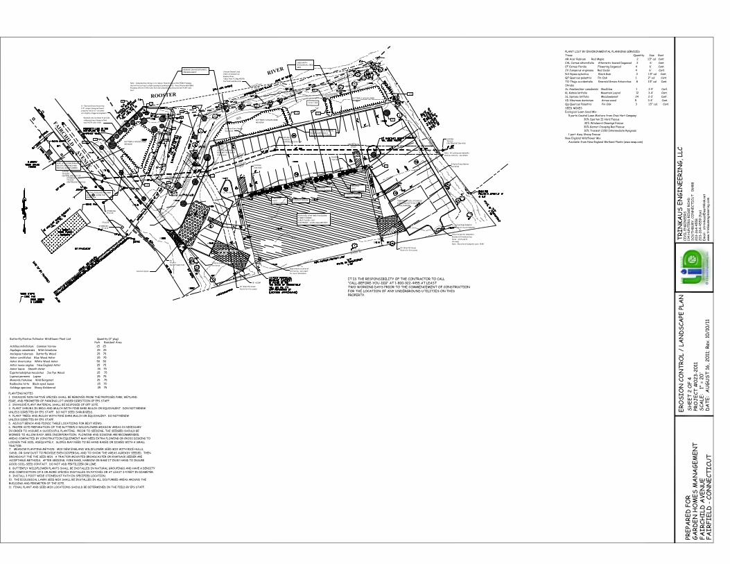
PLANT LIST BY ENVIRONMENTAL PLANNING SERVICES
Trees Quantity Size Root
AR Acer Rubrum Red Maple 2 1.5" cal Cont.
CAL Cornus alternifolia Alternativ-leaved Dogwood 2 6' Cont
CF Cornus florida Flowering Dogwood 4 6' Cont.JV Juniperus virginiana Red Cedar 4 6' Cont.
NS Nyssa sylvatica Black Gum 3 1.5" cal Cont.
QP Quercus palustris Pin Oak 1 2" cal Cont.
TO Thuja occidentalis Emerald Green Arborvitae 8 1.5" cal Cont.
Shrubs
Ac Amelanchier canadensis Shadblow 1 3-4' Cont.
KL Kalmia latifolia Mountain Laurel 12 3-4' Cont.
SL Spiraea latifolia Meadowsweet 24 2-3' Cont.
VD Viburnum dentatum Arrow-wood 5 3-4' Cont.
SEED MIXESEcological Lawn Seed Mix
5 parts Coastal Lawn Mixture from Chas Hart Company:
30% Spartan II Hard Fescue
30% Windward Chewings Fescue
30% Garnet Creeping Red Fescue
10% Transist 2200 Intermediate Ryegrass
1 part Azay Sheep Fescue
New England Wildflower Mix
Available from New England Wetland Plants (www.newp.com)
Butterfly/Native Pollinator Wildflower Plant List Quantity (2" plug)
Achillea millefolium Common Yarrow 25 25
Aquilegia canadensis Wild Columbine 25 25
Asclepias tuberosa Butterfly Weed 25 75
Aster cordifolius Blue Wood Aster 25 75
Aster divaricatus White Wood Aster 50 50
Aster novae angliae New England Aster 25 75
Aster laevis Smooth Aster 35 75
Eupatoriadelphus maculatus Joe Pye Weed 25 75
Lupinus perennis Lupine 25 75Monarda fistulosa Wild Bergamot 25 75
Rudbeckia hirta Black-eyed Susan 25 75
Solidago speciosa Showy Goldenrod 25 75
Park Resident Area
PLANTING NOTES
1. INVASIVE NON-NATIVE SPECIES SHALL BE REMOVED FROM THE PROPOSED PARK, WETLAND
EDGE, AND PERIMETER OF PARKING LOT UNDER DIRECTION OF EPS STAFF.
2. INVASIVE PLANT MATERIAL SHALL BE DISPOSED OF OFF SITE.3. PLANT SHRUBS IN BEDS AND MULCH WITH PINE BARK MULCH OR EQUIVALENT. DON NOT RENEW
UNLESS DIRECTED BY EPS STAFF. DO NOT SEED SHRUB BEDS.
4. PLANT TREES AND MULCH WITH PINE BARK MULCH OR EQUIVALENT. DO NOT RENEW
UNLESS DIRECTED BY EPS STAFF.
5. ADJUST BENCH AND PICNIC TABLE LOCATIONS FOR BEST VIEWS.
6. PROPER SITE PREPARATION OF THE BUTTERFLY/WILDFLOWER MEADOW AREAS IS NECESSARY
IN ORDER TO ASSURE A SUCCESSFUL PLANTING. PRIOR TO SEEDING, THE SEEDBED SHOULD BE
WORKED TO ALLOW EASY SEED INCORPORATION. PLOWING AND DISKING ARE RECOMMENDED.
AREAS COMPACTED BY CONSTRUCTION EQUIPMENT MAY NEED EXTRA PLOWING OR CROSS DISKING TO
LOOSEN THE SOIL ADEQUATELY, SLOPES MAY NEED TO BE HAND RAKED OR DISKED WITH A SMALLTRACTOR.7. MEADOW PLANTING METHOD: MIX NEW ENGLAND WILDFLOWER SEED MIX WITH RICE HULLS,
SAND, OR SAW DUST TO PROVIDE EVEN DISPERSAL AND TO SHOW THE AREAS ALREADY SEEDED. THEN
BROADCAST THE THE SEED MIX. A TRACTOR MOUNTED BROADCASTER OR KNAPSACK SEEDER AREACCEPTABLE METHODS. AFTER SEEDING, YORK RAKE, HARROW OR RAKE IT IN BY HAND TO INSURE
GOOD SOIL-SEED CONTACT. DO NOT ADD FERTILIZER OR LIME.
8. BUTTERFLY WILDFLOWER PLANTS SHALL BE INSTALLED IN NATURAL GROUPINGS AND HAVE A DENSITY
AND COMPOSITION OF 8 OR MORE SPECIES INSTALLED IN PATCHES OR AT LEAST 3-4 FEET IN DIAMETER.
9. INSTALL 3 FOOT WIDE STONEDUST PATH IN SPECIFIED LOCATION.
10. THE ECOLOGICAL LAWN SEED MIX SHALL BE INSTALLED IN ALL DISTURBED AREAS AROUND THE
BUILDING AND PERIMETER OF THE SITE.
11. FINAL PLANT AND SEED MIX LOCATIONS SHOULD BE DETERMINED IN THE FIELD BY EPS STAFF.
PROPERTY.FOR THE LOCATION OF ANY UNDERGROUND UTILITIES ON THISTWO WORKING DAYS PRIOR TO THE COMMENCEMENT OF CONSTRUCTION"CALL-BEFORE-YOU-DIG" AT 1-800-922-4455 AT LEASTIT IS THE RESPONSIBILITY OF THE CONTRACTOR TO CALL
Qp Quercus Palustris Pin Oak 3 1.5" cal. Cont.
GA
RD
EN
HO
ME
S M
AN
AG
EM
EN
TF
AIR
CH
ILD
AV
EN
UE
PRE
PAR
ED
FO
R
FA
IR
FIE
LD -
CO
NN
EC
TIC
UT
Em
ail:
stri
nkau
s@ea
rthl
ink.
net
ww
w.t
rink
ause
ngin
eeri
ng.c
om
TR
IN
KA
US
EN
GIN
EE
RIN
G, LL
CC
IVIL
EN
GIN
EE
RS
114
HU
NT
ER
S R
IDG
E R
OA
DS
OU
TH
BU
RY
, CO
NN
EC
TIC
UT
0
6488
20
3-2
64
-4558
20
3-2
64
-45
59 (
fax)
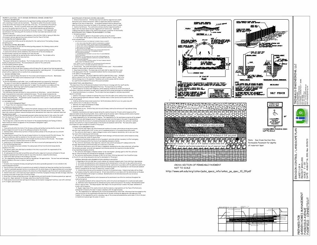
CROSS SECTION "A" - "A" SCALES:HORIZONTAL: 1" = 10'
VERTICAL: 1" = 4'
8
12
16
20
0 10 20 30 40 50 60 70 80 90
Stone Reservoir layer under Permeable Pavement
Bottom to be set level
15.66'
15.33'
14.66'
14.41'
12.91'
14.66'
14.33'
13.66'
13.41'
12.91'
Section through permeable pavement
4" PVC perforated underdrain - see
plan for more information
Ex. Grade
Landscape Bed
Building Slab Elevation (18')
Proposed Grade
Inv. of underdrain = 13.50'
Permeable Pavement
Chocker Course
Filter Course
Filter Blanket
Reservoir Course
BY THE DESIGN ENGINEER)
AMOUNT OF SEDIMENT REMOVED DURING EACH QUARTERLY OPERATION
(FREQUENCY OF VACUUMING MAY BE ADJUSTED AFTER OBSERVING THE
FOR POROUS ASPHALT" FOR MORE INFORMATION. (JUNE 2011)
NOTE: REFER TO UNHSC DOCUMENT ON "WINTER MAINTENANCE GUIDELINES
DEBRIS FROM THE PERMEABLE SURFACE.
2. USE LEAF BLOWERS AS NEEDED DURING THE YEAR TO REMOVE ORGANIC
SURFACE QUARTERLY.
1. USE REGENERATIVE AIR DIRECT VACUUM TRUCK TO CLEAN PERMEABLE
NON-WINTER MAINTENANCE:
OBSERVATIONS OF SNOW MELT ON PERMEABLE SURFACE.
5. AMOUNT OF DE-ICING TREATMENT SHALL BE ADJUSTED BASED UPON
AFTER PLOWING HAS OCCURRED.
4. ADDITIONAL DE-ICING TREATMENTS CAN BE APPLIED DURING SNOW EVENT
3. DO NOT APPLY SAND TO PERMEABLE SURFACE AFTER SNOW EVENT EVER.
2. PLOW AFTER EVERY STORM. RAISED BLADE IS NOT RECOMMMENDED.\
1. APPLY ANTI-ICING TREATMENTS PRIOR TO SNOW EVENTS AS NEEDED.
WINTER MAINTENANCE FOR PERMEABLE PAVEMENT/POROUS CONCRETE
http://www.unh.edu/erg/cstev/pubs_specs_info/unhsc_pa_spec_10_09.pdf
Native Materials
4" diameter perforated underdrain at top of reservoir layer
Reservoir Course: 6 - 18" layer of 3/4" washed crushed stone with
Filter Blanket: Intermediate settling bed: 3" thickness of 3/8" pea gravel
Filter Course: 8" of Bank-run sand and gravel
Chocker Course: 4" minimum thickness of 3/4" washed stone
Pervious Pavement (4" thick)
CROSS SECTION OF PERMEABLE PAVEMENT
NOT TO SCALE
is transferred is placed upon the owner of record.
transfer of this responsibility and for conveying a copy of the erosion and sedimentation control plan if title to the land
construction site of the requirements and objectives of the plan, notifying the appropriate town agencies of any
10. The responsibility for implementing the erosion and sedimentation control plan, informing all parties engaged on the
professional retained by the owner to assure compliance with the approved plans.
9. Regular inspections of the construction site shall be made by a representative of the Town of Fairfield and a
erosion control measures.
Officer requires them. The design engineer shall inspect the site periodically to ensure the proper installation of
8. Additional control measures will be installed during the construction period if the Zoning or Wetland Enforcement
7. Accumulated sediment will be removed from the control structures and disposed of in a lawful and safe manner.
construction period.
6. All erosion and sedimentation control measures will be maintained in an effective conditions throughout the
final grading in complete.
5. Land disturbance will be kept to a minimum. Restabilization of all disturbed areas will occur as soon as
as necessary during the construction period. All work done shall be in accordance with the details shown on the plans.
4. Siltation fence barriers will be installed at the limit of all disturbed areas. Staked straw bales, will be utilized
Control" as prepared by the State of Connecticut, revised to 2002.
details and in compliance with the specifications and standards found in the "Guidelines for Soil Erosion and Sediment
3. All erosion and sedimentation control measures shall be constructed in accordance with the submitted construction
2. All erosion and sedimentation control measures will be installed prior to the start of any construction activity.
1. Regrading on this site shall done in such a manner as to prevent stagnant water from collecting in depresssions.
GENERAL EROSION AND SEDIMENTATION CONTROL PLAN NOTES:
on the site for use during emergencies during the development of the project.
8. The contractor shall maintain a minimum of 150 lf of silt fence, 30 straw bales and 1 ton of modified riprap
may be contacted during the evenings and on weekends, if necessary.
7. The contractor shall supply a telephone number to the town engineer, planning agent so that the contractor
of any impending emergency situation.
the necessary personnel, materials and equipment and otherwise provide the required action when notified
6. The contractor shall have on call at all times, a responsible representative who, when authorized, will mobilize
drainage improvements on Fairchild Avenue are turned over to the town.
5. The contractor shall make a final inspection, clean all cross culverts and sweep off roadways before the
erosion control measures within four hours of any impending emergency situation.
4. The constactor shall make available on-site all equipment, materials and labor necessary to effect emergency
be necessary during the course of construction.
3. The contractor shall be prepared to implement interm drainage controls and erosion control measures as may
four hours after observing such deficiencies.
2. The contractor shall repair or replace damaged erosion control measures immediately, and in case, more than
and after each rainfall event of 0.5" or more, prior to weekends and prior to forecasted large storm events.
1. The contractor shall inspect the effectiveness and condition of erosion control devices during storm events,
CONTROL PLAN IMPLEMENTATION:
on all inspection reports prepared on behalf of the project.
and have the authority to require modifications to the Erosion and Sediment Control Plan. The town will be copied
the owner shall retain the services of a licensed professional who shall inspect and monitor the contractor's methods
to the contractor who shall designate one of its supervisory personnel to be the liason to the owner's representative.
j. Assign responsibility for the maintenance program. The responsibility for the maintenance program will be assigned
than 0.5 inches and repaired as needed to ensure that they function properly.
inspected weekly during the spring months, twice a month during the summer and/or following rainfall events of greater
i. Establish a maintenance and repair program during the construction period. Erosion control measures will be
the construction period.
h. Trap sediment on site. Siltation fence barriers and driveway construction entrance will trap sediment during
g. Maintain low runoff velocities.
f. Minimize the length and steepness of slopes.
active construction is to take place in this area.
e. Stabilize disturbed areas as soon as practical. Earth disturbance shall not occur on a given area until
extent of earthwork.
d. Retain existing vegetation wherever feasible. Siltation fence or other barriers will be used to limit the
c. Construct the project in phases to minimize the area of the site under active construction at one time.
impacts to wetlands.
b. Keep land disturbance to a minimum. The site layout has been designed to minimize any potential
disturbance, distribute stormwater through natural vegetation before being discharged into wetland systems.
a. Control erosion at its source with temporary control measures, minimize the runoff from areas of
earthwork operations by using Best Management Practices. The objectives are as follows:
The objectives of the Soil Erosion and Sediment Control Plan are to manage both the runoff and the
PLAN OBJECTIVES AND PRINCIPALS:
2.2 SOIL TEST RESULTS:
2.1 HYDRAULIC CALCULATIONS:
3. Project Plan Set comprised of Sheet 1 thru 3 of 3.
1. Storm Water Management Report
1.9 DOCUMENT LIST:
1.8 CONSERVATION PRACTICES:
and the Planning and Zoning Commission.
CT DEP guidelines. Monitoring reports shall be prepared and filed with the owner, contractor,
Certified Erosion & Sediment Control Specialist to inspect the site weekly in accordance with the
The owner of record shall be responsible for retaining a Licensed Professional Engineer or
As the site disturbance is well under 1 acre, no additional permits are required for this project.
1.7 OTHER PERMITS:
1.6 DESIGN INFORMATION:
1.5 CONSTRUCTION START DATES:
of the permeable pavement system.
building & underground utilities. The second phase will consist of the construction
This project will be done in two phases. The first phase shall consist of the the installation of the
1.4 CONSTRUCTION PHASES:
1.3 EROSION CONTROL MEASURES:
1.2 ESTIMATED DISTURBANCE AREA:
PROPERTY LOCATION: SOUTH ORANGE CENTER ROAD; ORANGE, CONNECTICUT
1.1 PROJECT DESCRIPTION:
Construction on the site will likely commence within 60 days after all requried local land use approvals
have been obtained from the Town of Fairfield assuming weather conditions permit. It is anticipated that
all work will be completed with six months from commencement date.
CONSTRUCTION PHASES:
This project proposes the construction of an apartment building containing 54 residential
units consisting of studio and one-bedrooms. The property contain 1.5 acres and is located
at the end of Fairchild Avenue on the east side of the road. It is bordered on the north by
the Rooster River. The site is currently vacant and a small topsoil processing operation is
be run on the southern portion of the site. A tidal wetland boundary was delineated by
Environmental Planning Services and located by the project surveyor. Field topographic data
was obtained in the field along with the location of all other man-made improvements on and
adjacent to the site.
It is anticipated that construction will commence in the late Fall of 2011 or Spring of 2012 after
all necessary land use approvals have been obtained from the Town of Fairfield.
It is estimated that 0.90 acres will be disturbed for the construction of the building, driveway
and parking areas.
Due to the flatness of the site and the minimal grading proposed, the following erosion control
measures will be implemented:
- Siltation fence barriers will be installed downgradient of all proposed grading activities.
- A construction entrance will be installed at the intersection of the site driveway and
Fairchild Avenue to prevent the tracking of dirt onto the road.
- A temporary stockpile will be used during the construction period. The stockpile will be
surrounded by staked siltation fence barriers.
There is no required design information for the erosion control measures on the site. Maintenance
requirements for the erosion control measures are part of this narrative.
Site distrubance has been minimized to reduce potential soil disturbance. Less soil disturbance
leads to less potential erosion and/or sedimentation issues. The site design incorporates one
Low Impact Development strategy, which is the use of Permeable Pavement for the majority of the
driveway and parking area. The pavement system incorporates a filter course to remove pollutants
from the post-development runoff.
The Stormwater Management report contains the hydraulic design process for the permeable pavement
system as well as the conventional drainage system to be used for the lower portion of the driveway. The
report also contains a pollutant renovation analysis which demonstates that reduction of pollutant loads from
non-point source runoff. The stone reservoir layer of the permeable pavement system has been sized to fully contain the runoff
from the majority of the parking area as well as the roof area below the invert of the underdrain pipe.
Two borings were conducted within the footprint of the proposed building by Soil Testing of Oxford.
These results are found in an appendix of the stormwater management report.
PHASE I:
1. Trees and brush within the limits of the driveway, parking and building locations shall be cleared. Brush
shall be chipped into mulch for use on the walkways as shown on the site plan.
2. Install perimter siltation fence barriers in those locations as shown on the site plan and in accord with
the attached detail.
3. Topsoil shall be removed from the new driveway location at its intersection with Fairchild Avenue. The
Construction Entrance shall be installed at this time and in accord with the submitted detail.
4. Topsoil shall be removed and placed in the stockpile location as shown on the site plan. The stockpile
shall be surrounded by a siltation fence barrier as shown.
5. Construction of the building shall commence at this time in accord with plans approved by the Town
of Fairfield Building Department.
6. Once the foundation has been installed, the underground utilities from Fairchild Avenue shall be
installed at this time.
7. The sanitary sewer later shall also be installed at this time in accord with the requirements of the
Fairfield Sewer Department.
8. All underground utilities shall be backfilled and sufficiently compacted to prevent settlement of the soil.
A temporary pavement patch shall be made for any utility line which crossed Fairchild Avenue.
9. Construction shall continue on the building at this time.
10. The compensating flood storage area shall be regraded per the approved plan. The new trees and landscaping
shall be installed in this area to create a "pocket park".
PHASE II:
1. Excavate area of proposed driveway and parking facility where permeable pavement is to be installed to the
required subgrade elevation.
2. Scarify bottom of side walls of excavated area as needed to eliminate soil smearing resulting from the excavation.
3. Construct permeable pavement section in accordance with the detail shown on the approved plans and in accordance
with the construction procedures outlined in the University of New Hampshire specifications for permeable pavement.
4. Install trench drain, catch basin and oil/grit separator at bottom of proposed driveway and make drainage connection
to existing catch basin on west side of Fairfield Avenue.
5. Grade lower driveway and parking area per the approved plan and install standard bituminous pavment per approved
cross section. Repair pavement for drainage connection across Fairchild Avenue.
6. Finish grade areas around lower parking and driveway and stormwater management facilities, cover with a minimum
of 4" of topsoil, seed and mulch.
MAINTENANCE OF EROSION CONTROL MEASURES:
1. Siltation fence barriers: Siltation fence barriers shall be inspected every month
during the active construction period. Fallen or ripped fence shall be repaired or
replaced at the time of observation. Accumulated sediment shall be removed from
above the siltation fence when the height of the sediment is greater than 6" in depth.
2. Construction Entrance: The construction entrance shall be inspected monthly to
ensure that the stone has not become clogged with dirt and/or mud. Additional
crushed stone shall be added to the construction entrance to maintain its functionality.
MAINTENANCE FOR STORMWATER MANAGEMENT SYSTEMS:
1. Permeable pavement:
a. No sand shall be applied to the pavement surface during the winter.
b. A leaf blower shall be used to remove any accumulated litter or organic debris
on an as needed basis.
c.
2. Trench Drain: The trench drain shall be inspected twice a year. Any accumulated
sediment or debris shall be removed from the drain.
3. Deep Sump Catch Basin: The deep sump catch basin shall be inspected twice a year,
in the Spring and in the Fall. Accumulated sediment shall be removed when the depth
is 24" (50% of the sump depth).
4. Oil/Grit Separator: The oil/grit separator shall be inspected twice a year. Sediment
shall be removed from the first chamber when the depth is greater than 12". Due to the
limited drainage area to the separator, floatables such as oils & grease shall be removed
by a qualified environmental firm every three years as needed.
Note: See Cross Section thru
Permeable Pavement for depths
of reservoir layer
20
3-2
64
-45
59 (
fax)
20
3-2
64
-4558
SO
UT
HB
UR
Y, CO
NN
EC
TICU
T 0
6488
114
HU
NT
ER
S R
IDG
E R
OA
DC
IVIL
EN
GIN
EE
RS
TR
IN
KA
US
EN
GIN
EE
RIN
G, LL
C
ww
w.t
rink
ause
ngin
eeri
ng.c
omE
mai
l:
stri
nkau
s@ea
rthlin
k.ne
t
FA
IR
FIE
LD -
CO
NN
EC
TIC
UT
PRE
PAR
ED
FO
R
FA
IR
CH
ILD
AV
EN
UE
GA
RD
EN
HO
ME
S M
AN
AG
EM
EN
TS
HE
ET
2 O
F 4
DA
TE
: A
UG
US
T 1
6,
20
11; R
ev. 1
0/1
0/1
1S
CA
LE:
1"
= 2
0'
PRO
JE
CT
#0
23-2
011
ER
OS
ION
CO
NT
RO
L /
LA
ND
SCA
PE P
LAN

FA
IRC
HIL
D A
VE
NU
E
RIVER
ROOSTER
SAN MHTF=10.99CENTERLINE INV=1.39
SAN MHTF=13.76CENTERLINE INV=3.17
SAN MHTF=15.41CENTERLINE INV=3.59
SAN MHTF=9.22CENTERLINE INV=4.50
CBTF=9.77INV 15"(NW)=5.45
CBTF=10.95
STORM MHTF=10.71
STORM MHTF=11.10
STORM MHTF=10.93CENTERLINE INV=2.60
N79°44'29"E
260.41'
S38°20'10"E
235.29'
L = 322 .70 '
R= 2441 .83
N47
°29'
47"E
60.9
1'
N89°53'46"W
179.87'
N89°53'46"W
186.26'
N72°29'33"E
81.02'
N72°29'33"E
81.38'
N86°06'08"E
82.51'
Concrete Apron
Stream Channel Lines
State of Connecticut
Rooster River
Taken from TC Map #3078
Fairfield Land Records
18" ACCMP
Em
ail: st
rink
aus@
ear
thlink
.net
ww
w.t
rink
ause
ngin
eeri
ng.c
om
GA
RD
EN
HO
ME
S M
AN
AG
EM
EN
TF
AIR
CH
ILD
AV
EN
UE
TR
INK
AU
S E
NG
INE
ER
ING
, LL
CC
IVIL
EN
GIN
EE
RS
114
HU
NT
ER
S R
IDG
E R
OA
DS
OU
TH
BU
RY
, CO
NN
EC
TICU
T 0
64
88
20
3-2
64
-45
58
20
3-2
64
-45
59
(fa
x)
EX
IST
ING
CO
ND
ITIO
NS
MA
P
PRO
JE
CT
#0
23
-20
11S
CA
LE:
1"
= 2
0'
DA
TE
: A
UG
US
T 1
6, 2
011
; R
ev. 1
0/1
0/1
1
PRE
PAR
ED
FO
R
FA
IRF
IELD
- C
ON
NE
CT
ICU
T
SH
EE
T 4
OF 4
APPLICANT: GARDEN HOMES MANAGEMENT
29 KNAPP STREET
STAMFORD, CT 06907
IT IS THE RESPONSIBILITY OF THE CONTRACTOR TO CALL"CALL-BEFORE-YOU-DIG" AT 1-800-922-4455 AT LEASTTWO WORKING DAYS PRIOR TO THE COMMENCEMENT OF CONSTRUCTIONFOR THE LOCATION OF ANY UNDERGROUND UTILITIES ON THISPROPERTY.
TW (across creek)FWW (no inland wetlands at site per soil scientist)
EM & NCW (downstream of site)
CH (entire site)
CH Coastal Hazard Area
FWW Freshwater wetlands & watercourses
NCW Nearshore Coastal Waters
EM Estuarine Embayment
TW Tidal Wetlands