Embed Size (px)
Citation preview

Lego beyond toysTechnology Class
Final reportMaarten BrugmansS040203
December 2009

Lego beyond toysTechnology class
Department of Industrial DesignEindhoven University of Technology
Final reportMaarten [email protected]

Introduction
Task description“This master class prepares for a new type of engineering discipline: design and crea-tion of intelligent systems, products, and related services. The class will be a unique opportunity to get familiar with a number of powerful conceptual and intellectual tools to understand and create adaptive behavior at a system level. The context of Lego is chosen because it is already an example of a system. But in this class the crea-tive goal is to make a leap forward, extending the scope of the existing system such that adaptive behavior becomes the central theme. The new Lego should be equally fascinating for grown-ups and children, women and men.
System level thinking has had and still has an enormous impact upon the development of technology. When working at a system level one does not study individual compo-nent behavior, such as Ohm’s law for an electrical component; instead one addresses bigger questions such as the stability of the feedback loops, information throughput, or learning capacity. (...) Using this, next to the existing Mindstorm components, a fascinating demonstrator is designed, perhaps a piece of electronic art or a life-like creature.”
Concept: Lego indoor navigation systemWhen looking at the many websites on Lego Mindstorms and NXT, it becomes clear that almost all common analog and digital sensors are already available as Lego exten-sions. Some of them are created by Lego, and others come from third parties like Mindsensors [2]. After some benchmarking, two main ideas emerged: a positioning/navigation system for a small (indoor) space, which adds to the lack of indoor functionality of GPS, and to the fact that an optical sensor (such as created during the previous Technology Class) does not provide coordinates, but only replacement. The second main idea was to create a solar panel which can tilt itself towards the optimal angle, in order to gain as much solar power as possible.
From an identity-point of view, designing a system has my personal preference. I tend to work more on system design instead of product design in recent projects, and creating a system of Lego extensions would be a good and logical addition to that. Secondly, the solar panel concept would mainly focus on mechanics and software solutions, while working on a combination of system design, electronics and software has my preference, considering my overall learning goals and identity. Because of this, I chose the positioning system as my set of extensions for this class.
Indoor navigation systems: existing solutionsBenchmarking different ranges of existing indoor navigation systems gives a good overview of the principles behind these systems. Systems like IPS (Indoor Positioning System) and WITTS use a network of beacons and transponders. The beacons are fixed on a known location within the space, and the transponders move around, attached to objects or people. The transponders send out an unique signal, which is received by the beacons. Based on this, the location of the transponder can be calculated. Positioning can also be done by using a Wifi network, which is practical, because Wifi is available in many places. Unfortunately, the best accuracy is around two meters. RFID technology is also applied, but it only provides room-level accuracy. The RFID antennas are usually placed in doors, which enables the system to identify in which room of a building a RFID tag (and their accompanying object or person) can be found. Finally, GPS repeaters are available, which receive a GPS signal outside the building, and pass it on into the building. Besides the fact that these systems are expensive (around 1000 euro’s), they usable for indoor navigaion, because they re-emit the GPS signal instead of indicating the true position.
Concept choicesBased on the benchmark results above, a small scale Lego positioning system should be based on a concept like IPS, which is a network of beacons and a transponder, because it’s most accurate, affordable and flexible to operate. An Indoor Positioning System can rely on different types of signals, but the most com-monly used signals are infrared light and ultrasonic sound. After consulting experts on this topic, I concluded that infrared would be the best solution. Ultrasonic sound has the disadvantage of resonance: sound waves bounce back from walls and other objects, making it hard to distinguish the location of the transponder. Infrared sensors have internal noise filters, which overcome this problem. The main disadvantage of infrared however is that the line between the beacon and the transponder should not be visually blocked by objecs. On the other hand, infrared LEDs and sensors are cheap, which helps to keep the Lego extensions affordable, or at least within the price range of the other extensions. Because of this consideration I also decided to use a digital infrared sensor.

System overview
The Lego Positioning System consists of four main components: the existing Lego NXT brick, a receiver and two (identical) beacons. The beacons are located on two fixed points within the space, and the distance between them should also be fixed and known. The receiver emits an infrared signal, which is received by the beacons.
System overview: the two beacons, the receiver and the NXT brick.
The beacons then communicate the angle on which they detected the robot back to the receiver. The receiver calculates the robots coordinates based on the angles it received from both beacons, and based on the distance between the beacons. It then communicates the coordinates to the Lego NXT brick. The coordinates can be used by the NXT brick for any desired purpose.

Electronics: Beacons
Arduino Pro MiniThe central processing of the beacons is done by an Arduino Pro Mini with ATmega168 chip (operating voltage 5V and a clock speed of 16 MHz). The Pro Mini basically provides the same func-tionality as the more common Arduino Duemilanove. However, the Pro Mini is very small (18 x 33 mm), and comes without connector pins and USB connector. Therefore, it’s more labor-intensive to operate, but due to its size and functionality, it’s very useful for small, stand-alone prototypes [1].
Within the beacons of the Lego Positioning System, the Arduino Pro Mini controls the servo motor, and powers and reads the infrared sensor. Aditionally, it sends the robot’s angle to the con-nected Xbee via serial communication.
Xbee and Explorer Regulated shieldThe Xbee module [4] is directly connected to the Arduino Pro mini via an Explorer Regulated shield [3]. It connects the Vcc, ground, Rx, Tx pins and powers the Xbee with the right supply voltage (3.3V).
Servo motorA simple servo motor is used to rotate the sensor physically. The servo is connected to the Arduino, and contolled by one of the PWM pins.
Infrared sensorThe TSOP2438 infrared receiver was chosen as sensor for the beacons. It is small, cheap, and has a large transmission distance (up to 35 meters). Furthermore, it has an internal 38kHz fre-quency filter, which filters out noise and disturbance (e.g. from ambient light).
Other circuitriesFinally, a on/off switch and a power indicator LED were added to the beacon.
Custom Arduino shieldIn order to connect the Arduino Pro Mini with the other compo-nents, a small shield was created. [insert pictures of shield]. The
shield contains connectors for the servo, the Xbee shield, and supply voltage wires (9V and 5V DC).
ImplementationAll components and circuits were connected and tested on a breadboard, and were implemented in small scale circuits for the beacon prototypes after-wards.
Testing the Xbee modules with Arduino TSOP2438 application circuit
Electronics: Receiver and IR emitter
Arduino Pro Mini and Xbee and Explorer Regulated shieldThe Arduino and Xbee components used within the receiver are indentical to the ones used in the beacons. These components are discussed in the previous section.
Timing circuitsBecause of the fact that the TSOP2438 has an internal frequency filter, the infrared signal has to be a 38kHz signal. Furthermore, it needs to be emitted in bursts of 10 to 35 cycles, followed by a gat time of at least 14 cycles. To create this signal with analog electronics, two timing circuits (astable multivibra-tors or AMV’s) were needed. These AMV’s can be created by using the TLC555 timer, which is a multi-purpose IC. By applying it in an application circuit as shown below, it can be used to create an AMV. By changing the values of R1, R2 and C1, a wide range of output frequencies can be achieved. In order to create the desired infrared signal, a 38kHz timer was needed, as well as an 1900Hz timer. 1900Hz is 20 times longer than 38kHz, so when powering the 38kHz timer with the 1900Hz timer, the output signal is a 38kHz frequency of 20 cycles, fol-lowed by a break of 20 cycles. This signal can be received by the TSOP2438 infrared receiver, as described within the previous section.
TLC555 application circuit, creating an Testing the timing circuits on a breadboard.(AMV). Image: www.daycounter.com
The two timers connected, generating the desired output signal
Custom Arduino shieldThe custom Arduino shields are identical to the ones created for the beacons, except for the servo connector.
LED driver circuitThe infrared LED’s are powered from the 9V battery via a resistor, creating a 7V supply. This is higher than the usual supply voltage, but because of the fact that a frequency generator (the AMV’s) will be used to control the LED’s, this is possible, and this increases the light intensity of the LED’s. In order to make sure that not too much cur-rent will flow through the timing circuits, two FET’s are used. A FET is quite similar to a regular transistor, but it has an internal diode that blocks any current flowing from the gate (equivalent of the base of a transistor) to the drain (equivalent of the emitter). The components are connected as shown in the schematic of the two timers (left of this page). Within the prototype, two FET’s are used, which each power four LED’s.
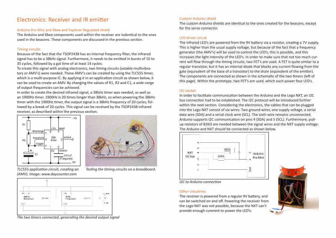
I2C socketIn order to facilitate communication between the Arduino and the Lego NXT, an I2C bus connection had to be established. The I2C protocol will be introduced further within the next section. Considering the electronics, the cables that can be plugged into the Lego NXT consist of six wires: Two ground wires, one supply voltage, a serial data wire (SDA) and a serial clock wire (SCL). The sixth wire remains unconnected. Arduino supports I2C communication on pins 4 (SDA) and 5 (SCL). Furthermore, pull-up resistors of 82KΩ are needed between the signal wires and the NXT supply voltage. The Arduino and NXT should be connected as shown below.
I2C to Arduino connection
Other circuitriesThe receiver is powered from a regular 9V battery, andcan be switched on and off. Powering the receiver fromthe Lego NXT was not possible, because the NXT can’t provide enough curerent to power the LED’s.

Software
IntroductionThe schematic below provides an on overview of the main software functions within the different components of the system. It also shows how they are connected, and how data is ex-hanged between the components. For a more detailed overview of the code, please see the appendix.

Hardware
Beacon and receiver casingsThe casings of the beacons and the receiver are relatively simple boxes, and were therefore created out of 4mm thick MDF, using the laser cutter. On the inside, three partitions were created, in order to be able to mount the electronics at the right place. After lasercutting the MDF, the parts were assembled and glued. When assem-bled, they were sanded, painted with primer and grey paint.
Assembling the lasercutted MDF parts
IR sensor casingsThe infrared sensor casings are placed on top of the beacon casings, and are the rotating parts of the prototype. Due to their small size, and required precision in their measurements, they were drawn in SolidWorks, and 3D printed. When printed, the parts were cleaned, sanded with different kinds of sandpaper, and painted in the same order as the MDF parts. This results in a very smooth surface finish.
IR LEDs casingIdentically to the IR sensor casings, the IR LEDs casing was created through 3D print-ing.
3-Hole Lego connectorsIn order to make the parts easily connectable to other Lego components, 3-hole connectors were drawn and 3D printed. Two connectors were added to each of the components.
The 3D printed parts, before the sanding and spray painting.
Lego robotThe first version of the Lego robot was quickly created before the deadline, and con-tained two mistakes: it had too much internal friction, and the IR emitter was too high above the ground. A second version, as shown in the picture below, was created after the presentation, eliminating the two mistakes.
The redesigned Lego robot
Technical drawingsFor technical drawings of the various components, please see the appendix.

Discussion
Possible improvementsWithin the time available for this project, it has not been possible to optimize the resolution of the system, for example by improving the software. However, I will briefly discuss possible improvements within this section.
Software optimalizationConsidering the software, the system could have been made more “smart”. For ex-ample, when the beacon has detected the robot within a certain angle, it could then measure more specifically around the detected angle, instead of searching the entire 90° range, which takes relatively much time. This would make the system faster and more accurate.
System resolutionThe system resolution can be calculated with simple trigonometry. If the distance between the beacon (B)and the robot (R) is, for example, 1 meter (1000mm), the uncertainty (distance l) will be:
1000 * tangens(1°) = 17,5 mm.
If the distance BR is 3 meter (3000mm), the uncertainty will be:
3000 * tangens(1°) = 52,4 mm.
Furthermore, if the distance BR is 5 meter (5000mm), the uncertainty will be:
5000 * tangens(1°) = 87,3 mm.
This calculation however assumes that the robot will not be moving, and that the IR sensor will be able to detect the precize angle in which the robot is located. Unfortunately, this is highly dependent on the direction of the IR LED compared to the IR sensor. A Calculation of the resolutionLED emits more light straight ahead than to the sides, even though their emission angle is 60 degrees. Especially when the robot is located further away from the beacons, this problem occurs.
Possible solutions to this problem could be the installation of much more LEDs, each
covering an area of about 10 degrees, which would result in 36 instead of the cur-rently installed 8 LEDs. A light source that emits the light equally around 360 degrees would be even better, for examples using OLED technology. Otherwise the light can be reflected by a circular mirror. When tilted 45 degrees and illuminated from below, it can create an equal signal at all 360 degrees.
Additionally, using an analog infrared sensor would probably be better, because it could determine on which angle the infrared signal is the strongest, instead of taking the average of the digital measurements. When using LEDs instead of an equally emit-ting light source, this could help the system to become more accurate.
Other technologiesIn robotics, other technologies are applied to solve this problem. For example, ultra-sonic sound is used instead of infrared. However, when using ultrasonic sound indoor, the problem of resonance comes into play. This is no problem when measuring the distance between two objects (such as with common distance sensors), but it be-comes more problematic when detecting the angle of the source of the signal.
Laser technology is also applied in robotics, and is obviously more precize than infra-red or ultrasonic sound. However, it is much more expensive. Additionally, it’s prob-ably not a good idea to implement laser light in toys.
More beaconsThe system can become more reliable by using more than two beacons. Using three or four of them, and taking the average of their findings as optimal coordinates would al-ready make the system much more accurate. However, within the time and resources available for this task, creating two beacons was the maximum result.
distance BR
B (beacon)
R (robot)
distance l
angle α = 1°
Reflection
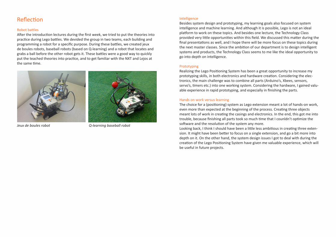
Robot battlesAfter the introduction lectures during the first week, we tried to put the theories into practice during Lego battles. We devided the group in two teams, each building and programming a robot for a specific purpose. During these battles, we created jeux de boules robots, baseball robots (based on Q-learning) and a robot that locates and grabs a ball before the other robot gets it. These battles were a good way to quickly put the teached theories into practice, and to get familiar with the NXT and Lejos at the same time.
Jeux de boules robot Q-learning baseball robot
IntelligenceBesides system design and prototyping, my learning goals also focused on system intelligence and machine learning. And although it is possible, Lego is not an ideal platform to work on these topics. And besides one lecture, the Technology Class provided very little opportunities within this field. We discussed this matter during the final presentations as well, and I hope there will be more focus on these topics during the next master classes. Since the ambition of our department is to design intelligent systems and products, the Technology Class seems to me like the ideal opportunity to go into depth on intelligence.
PrototypingRealizing the Lego Positioning System has been a great opportunity to increase my prototyping skills, in both electronics and hardware creation. Considering the elec-tronics, the main challenge was to combine all parts (Arduino’s, Xbees, sensors, servo’s, timers etc.) into one working system. Considering the hardware, I gained valu-able experience in rapid prototyping, and especially in finishing the parts.
Hands on work versus learningThe choice for a (positioning) system as Lego extension meant a lot of hands-on work, even more than expected at the beginning of the process. Creating three objects meant lots of work in creating the casings and electronics. In the end, this got me into trouble, because finishing all parts took so much time that I counldn’t optimize the software and the resolution of the system any more. Looking back, I think I should have been a little less ambitious in creating three exten-sion. It might have been better to focus on a single extension, and go a bit more into depth on it. On the other hand, the system design issues I got to deal with during the creation of the Lego Positioning System have given me valuable experience, which will be useful in future projects.

References
[1] Arduino Pro Mini: http://www.arduino.cc/en/Main/ArduinoBoardProMini[2] Mindsensors: http://www.mindsensors.com[3] Xbee Explorer Regulated shield: http://www.sparkfun.com/commerce/product_info.php?products_id=9132[4] Xbee module: http://www.digi.com/products/wireless/point-multipoint/xbee-series1-module.jsp#overview

Appendix I: Technical drawings
Beacon casings
LED emitter casing1,
800
4
1,80
01,
800
14,2
0024
,200
31,2
0021
,200
40,100
9,900
2
103,
800
99,8
00
18,8005
2
65,800
61,8002
R3,1002
DRAWN
DATENAME
CHECKED
ENG APPR.
MFG APPR.
Q.A.
SHEET 1 OF 1WEIGHT: DO NOT SCALE DRAWING
FINISH
MATERIAL
REV.
ADWG. NO.
COMMENTS:
SIZE
beacon techdrawing
PROPRIETARY AND CONFIDENTIAL
<INSERT COMPANY NAME HERE>. ANY
WITHOUT THE WRITTEN PERMISSION OF
PROHIBITED. APPLICATION
REPRODUCTION IN PART OR AS A WHOLE
<INSERT COMPANY NAME HERE> IS
DRAWING IS THE SOLE PROPERTY OF
USED ON
THE INFORMATION CONTAINED IN THIS
NEXT ASSY
DIMENSIONS ARE IN INCHESTOLERANCES:FRACTIONALANGULAR: MACH BEND TWO PLACE DECIMAL THREE PLACE DECIMAL
SCALE:1:1
SolidWorks Student LicenseAcademic Use Only
6
19
16
12
50
15
4 3 2
DO NOT SCALE DRAWING
led unit assemblySHEET 1 OF 1
UNLESS OTHERWISE SPECIFIED:
SCALE: 1:1 WEIGHT:
REVDWG. NO.
ASIZE
TITLE:
NAME DATE
COMMENTS:
Q.A.
MFG APPR.
ENG APPR.
CHECKED
DRAWN
5
FINISH
PROHIBITED.
PROPRIETARY AND CONFIDENTIAL
TWO PLACE DECIMAL
MATERIAL
THREE PLACE DECIMAL
NEXT ASSY
INTERPRET GEOMETRIC
USED ON
BEND
TOLERANCING PER:
APPLICATION
DIMENSIONS ARE IN INCHESTOLERANCES:FRACTIONALANGULAR: MACH
THE INFORMATION CONTAINED IN THISDRAWING IS THE SOLE PROPERTY OF<INSERT COMPANY NAME HERE>. ANY REPRODUCTION IN PART OR AS A WHOLEWITHOUT THE WRITTEN PERMISSION OF<INSERT COMPANY NAME HERE> IS
1
50
12,2
00 20
SolidWorks Student LicenseAcademic Use Only

Infrared sensor casings
Lego 3-hole connector
ENG APPR
CHECKED
DRAWN
DATENAMEDIMENSIONS ARE IN INCHESTOLERANCES:FRACTIONALANGULAR: MACH BEND TWO PLACE DECIMAL
7,600
9,60
0
R3,9007,100
5,100
24,900
7,60
0
SolidWorks Student LicenseAcademic Use Only
47,
200
5,90
0
6,700
23
18,0
20
5,450R
23
6,50
0
14,5
00
317R
2,90
0
23,9
58
23
REV.
ADWG. NO.SIZE
MATERIAL
FINISH
DO NOT SCALE DRAWINGAPPLICATION
USED ONNEXT ASSY
THE INFORMATION CONTAINED IN THISDRAWING IS THE SOLE PROPERTY OF
REPRODUCTION IN PART OR AS A WHOLE
PROHIBITED.
COMMENTS:
SHEET 1 OF 1
Q.A.
MFG APPR.
ENG APPR.
CHECKED
<INSERT COMPANY NAME HERE>. ANY
WITHOUT THE WRITTEN PERMISSION OF
PROPRIETARY AND CONFIDENTIAL
NAME
<INSERT COMPANY NAME HERE> IS
DATE
sensor casing assembly
DRAWN
WEIGHT:
DIMENSIONS ARE IN INCHESTOLERANCES:FRACTIONALANGULAR: MACH BEND TWO PLACE DECIMAL THREE PLACE DECIMAL
SCALE:2:1
SolidWorks Student LicenseAcademic Use Only

Appendix II: Arduino code
Beacons
#include <Servo.h>
Servo servo; // create servo object to control a servo
int servoPin = 9; // servo is connected to pin 3int sensorPin = 3; // sensor input connected to pin 5int robotAngle; // the defined angle of the robotint minAngle; int maxAngle;int range;int midRange;int sensorVal;boolean minStored = false;boolean maxStored = false;
void setup() { pinMode(servoPin, OUTPUT); pinMode(sensorPin, INPUT); servo.attach(servoPin); Serial.begin(9600);}
void loop() { rotateSensorForward(); delay(10); sendAngle(); delay(100); rotateSensorBackward(); delay(10); sendAngle(); delay(100);}
void rotateSensorForward() { //rotate 0 --> 90 degrees for (int f=0; f<90; f++) {
//Serial.print(“ f=”); //Serial.print(f); servo.write(f); sensorVal = digitalRead(sensorPin); if(!minStored && sensorVal == 0) { minAngle = f; minStored = true; } if(minStored && sensorVal == 0) { maxAngle = f; } delay(30); //servo.refresh(); } range = maxAngle - minAngle; midRange = range / 2; robotAngle = minAngle + midRange; minStored = false; minAngle = 90; maxAngle = 90; sendAngle(); }
void rotateSensorBackward() { //rotate 90 --> 0 degrees for (int b=90; b>0; b=b-1) { //Serial.print(“b=”); //Serial.print(b); servo.write(b); sensorVal = digitalRead(sensorPin); if(!maxStored && sensorVal == 0) { maxAngle = b; maxStored = true; } if(maxStored && sensorVal == 0) { minAngle = b; } delay(30); //servo.refresh(); } range = maxAngle - minAngle; midRange = range / 2;

robotAngle = minAngle + midRange; maxStored = false; minAngle = 0; maxAngle = 0; sendAngle(); }
void sendAngle() { // send angle via Xbee Serial.print(robotAngle, BYTE); // Beacon A: Angle between 0-90}
Receiver
#include <string.h>#include <Wire.h>#include <math.h>
#define senderLength 2 //Length of I2C arraybyte sender[senderLength]; //I2C array
int angleA;int angleB;double radA;double radB;double robotX;double robotY;int distance = 30; // distance be-tween the beacons in cm
void clearSenderArray(void) { sender[0] = 1; sender[1] = 1;}
void requestEvent() { Wire.send(sender, senderLength);}
void calculateCoordinates() { // convert degrees to radians radA = (angleA / (180/(PI))); radB = (angleB / (180/(PI))); // calculate y-coordinate robotY = (distance / ( (1/(tan(radA))) + (1/(tan(radB))) ) ); // calculate x-coordinate robotX = (distance / (tan(radA))); // set maximum coordinates to 255 (reach of IR sensors) if (robotX > 255) {

robotX = 255; } if (robotY > 255) { robotY = 255; } // set sender bytes for NXT sender[0] = robotX; sender[1] = robotY;}
void setup() { Serial.begin(9600); Wire.begin(27); // join i2c bus with address 127 Wire.onRequest(requestEvent); // request event clearSenderArray(); }
void loop(){ if (Serial.available() > 0) { byte receivedByte = Serial.read(); int val = (int) receivedByte; if (val < 100) { // received from beacon A angleA = val; } if (val >= 100) { // received from beacon B angleB = val - 100; } calculateCoordinates(); delay(10); } delay(100);}
NXT brick (Java)
import lejos.nxt.*;
public class NXT_coordinates {
public static void main(String[] args) { I2CSensor Arduino = new I2CSensor(SensorPort.S1); byte[] buf = new byte[2]; for(int i = 0; i <2; i++){ buf[i] = 0; } LCD.refresh(); Arduino.setAddress(27); while(!Button.LEFT.isPressed()){ Motor.A.setSpeed(200); Motor.A.backward(); Motor.B.setSpeed(300); Motor.B.backward(); try { Thread.sleep(2000); } catch (Exception e) { } Arduino.getData(0, buf, 2); LCD.drawString(“Updating...”, 2, 7); try { Thread.sleep(200); } catch (Exception e) { } LCD.drawString(“ “, 0, 7); LCD.clear();

LCD.drawString(“My coordinates:”, 1, 0); LCD.drawString(“X = “, 5, 3); LCD.drawInt(buf[0], 10, 3); LCD.drawString(“Y = “, 5, 4); LCD.drawInt(buf[1], 10, 4); } LCD.clear(); LCD.drawString(“Shutting down...”, 5, 0); try { Thread.sleep(1000); } catch (Exception e) { } } }