Embed Size (px)
Citation preview
1
Lecture 12: Lasers
• Intro to Lasers
• Laser is an oscillator
• Conditions for laser oscillation
• Laser threshold
• Optical resonators
• Laser modes
• Gain saturation
• Steady-state laser internal photon flux density
• Brief discussion on laser systems
Reading: Senior 6.2.4-6.2.5
2
Before the laser
• Before the invention of the laser the available light sources were essentially either thermal (e.g. tungsten filament lamp) or spontaneous emission from atoms and molecules (e.g. gas discharge)
• In either case their brightness was limited by the temperature of the emitter
E.g. the broadband white light of solar radiation is limited in the brightness of the spectral lines by the temperature of the gases (recall black-body radiation)
• Light from a thermal or spontaneous emission source is incoherent – individual atoms radiating at random without any relation to one another
3
Coherent radiation
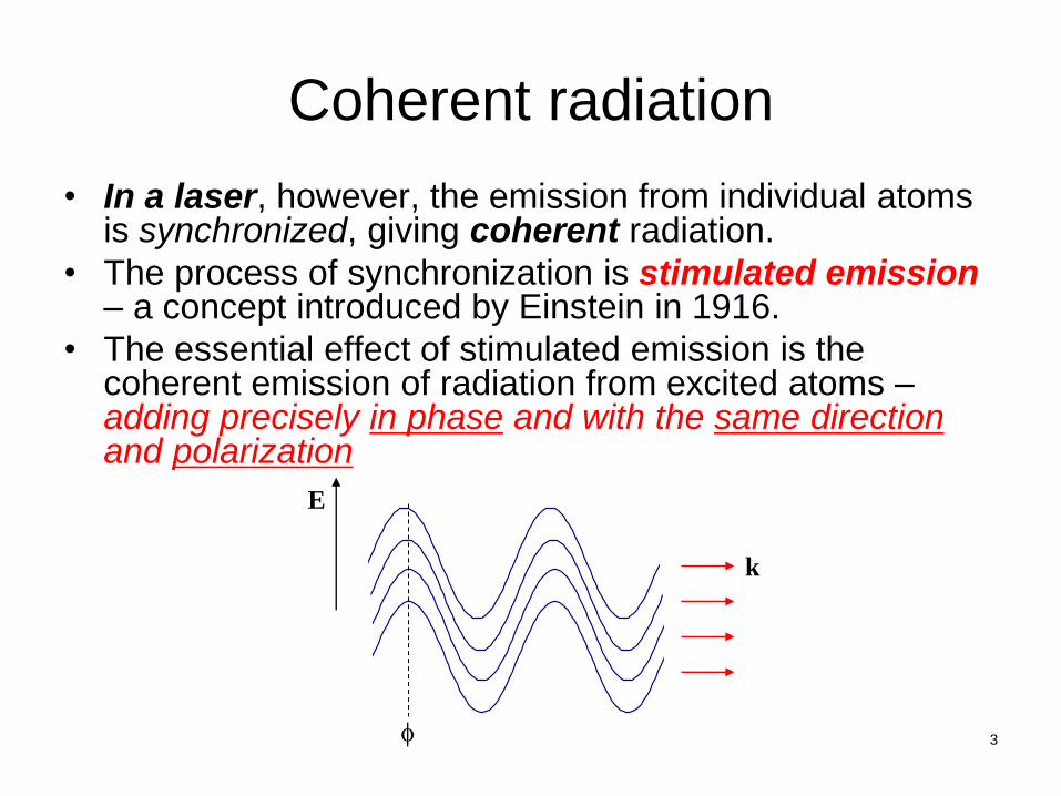
• In a laser, however, the emission from individual atoms is synchronized, giving coherent radiation.
• The process of synchronization is stimulated emission – a concept introduced by Einstein in 1916.
• The essential effect of stimulated emission is the coherent emission of radiation from excited atoms – adding precisely in phase and with the same direction and polarization
f
k
E
4
Stimulated emission
• One photon arrives at the excited atom, and two photons leave, with the same energy, traveling together and in phase
• The stimulated photon has the same momentum as the incident photon, and hence travels in the same direction
• Both photons can then repeat the stimulated emission process at other excited atoms
=> the resulting chain reaction causes the light wave to grow exponentially!
• To make such an amplifier into a self-excited oscillator – the light must be fed back into the laser material. This is attained by enclosing the lasing material between mirrors, forming a resonant cavity.
5
From coherent microwave to coherent lightwave
• The first use of stimulated emission to achieve coherent radiation was in the microwave spectrum – known as “maser” (microwave amplification by stimulated emission radiation)
• In 1953, James Gordon and Charles Townes demonstrated stimulated emission between the two lowest levels of ammonia molecules, giving a narrow emission line at a wavelength of 12.6 mm.
• In 1960, the first laser was demonstrated by Ted Maiman.
• LASER – light amplification by stimulated emission radiation
• Maiman generated red laser light at a wavelength of 694.3 nm from the chromium ions in a ruby crystal.
Laser turns 51 years old in 2011!
6
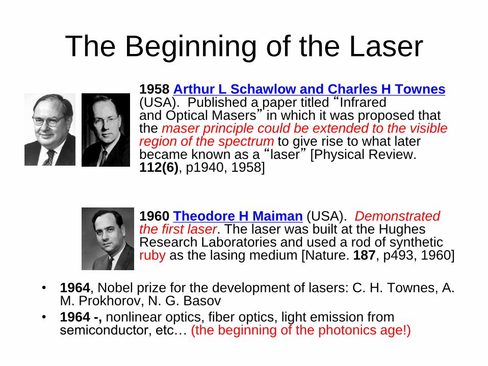
1958 Arthur L Schawlow and Charles H Townes (USA). Published a paper titled “Infrared and Optical Masers” in which it was proposed that the maser principle could be extended to the visible region of the spectrum to give rise to what later became known as a “laser” [Physical Review. 112(6), p1940, 1958]
1960 Theodore H Maiman (USA). Demonstrated the first laser. The laser was built at the Hughes Research Laboratories and used a rod of synthetic ruby as the lasing medium [Nature. 187, p493, 1960]
• 1964, Nobel prize for the development of lasers: C. H. Townes, A. M. Prokhorov, N. G. Basov
• 1964 -, nonlinear optics, fiber optics, light emission from semiconductor, etc… (the beginning of the photonics age!)
The Beginning of the Laser
7
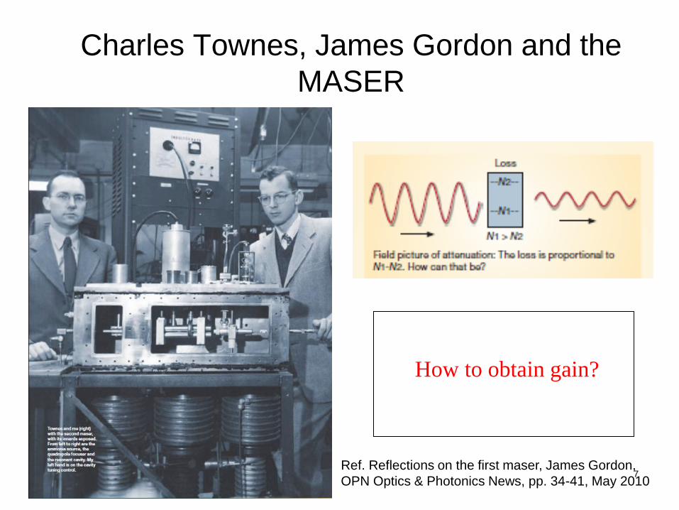
Charles Townes, James Gordon and the
MASER
How to obtain gain?
Ref. Reflections on the first maser, James Gordon,
OPN Optics & Photonics News, pp. 34-41, May 2010
8
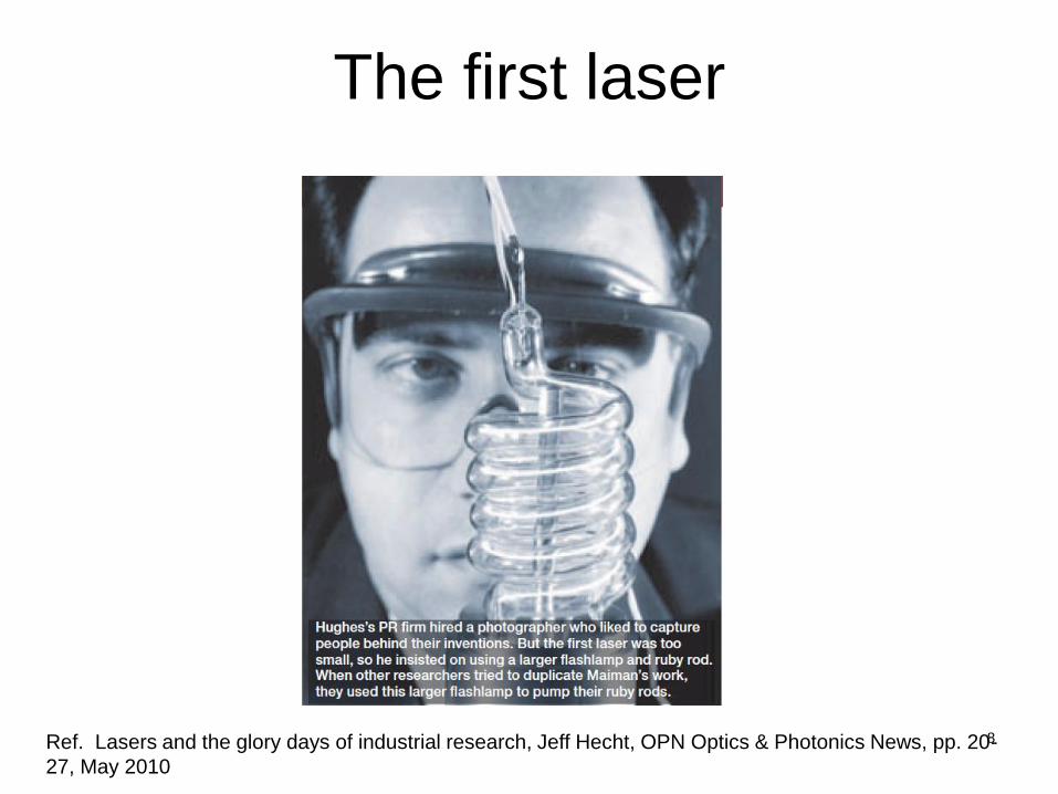
The first laser
Ref. Lasers and the glory days of industrial research, Jeff Hecht, OPN Optics & Photonics News, pp. 20-
27, May 2010
9
Laser light is
• Coherent
• Quasi-monochromatic (nearly single frequency), from soft x-ray (few nm) to mid-IR (e.g. 10.2 mm)
• Directional
• Polarized
• Can be high-power (e.g. kilo Watts)
• Can be continuously operated (continuous wave) or pulsed with narrow pulse widths (picosecond, femtosecond, attosecond)
• Can be generated from gas, liquid, solid medium (almost anything can become a laser if you pump it hard enough!)

10
More on stimulated emission
• Recall that the stimulated emission photon is an exact copy of the seed photon (identical frequency, phase, polarization and direction).
• Each stimulated emission photon could stimulate more photon emissions, leading to the build-up of a coherent wave of very large intensity.
• This requires the number of atoms in the higher energy level N2 to exceed the number in the lower level N1, a condition known as population inversion,
=> the rate of stimulated emission exceeds the rate of absorption.
11
Three-level lasers
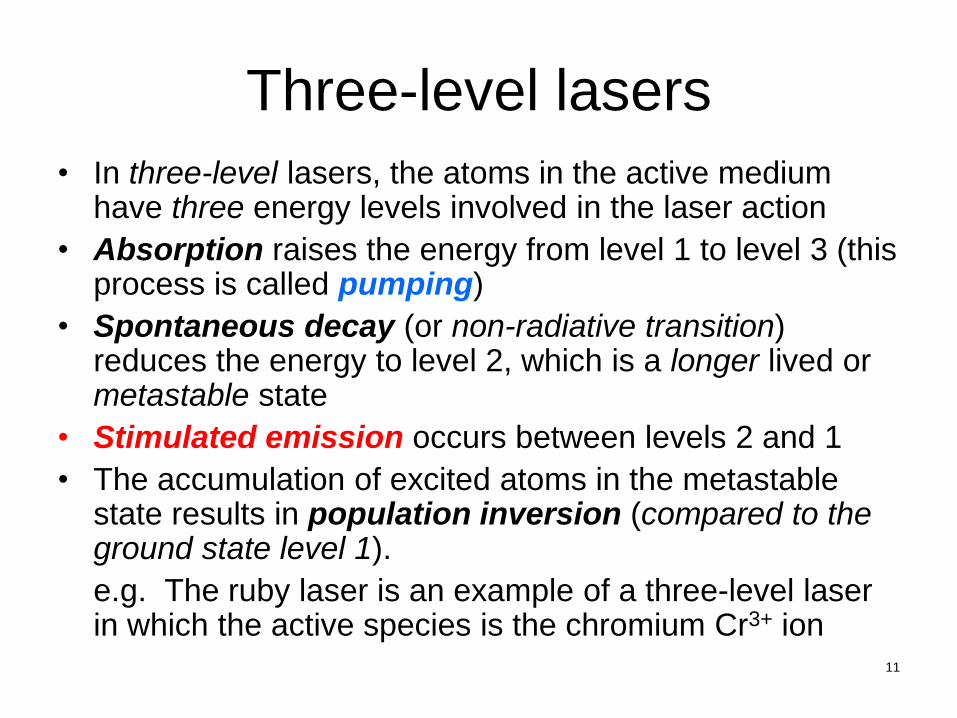
• In three-level lasers, the atoms in the active medium have three energy levels involved in the laser action
• Absorption raises the energy from level 1 to level 3 (this process is called pumping)
• Spontaneous decay (or non-radiative transition) reduces the energy to level 2, which is a longer lived or metastable state
• Stimulated emission occurs between levels 2 and 1
• The accumulation of excited atoms in the metastable state results in population inversion (compared to the ground state level 1).
e.g. The ruby laser is an example of a three-level laser in which the active species is the chromium Cr3+ ion

12
Population inversion in a three-level laser
• The energy supply used to create the population inversion is often referred to as a pump, which can be light absorbed between a ground level E1 and an excited level E3.
• If the excitation of this level is short-lived, and it decays to a lower but longer-lived level E2, the process leads to an accumulation and overpopulation of atoms in level E2 compared with E1. Stimulated emission, fed by energy from a pump, is the essential process in a laser.
E1 (ground)
E2 (long-lived)
E3 (short-lived)
pump
Spontaneous decay
Laser transition
13
Oscillators
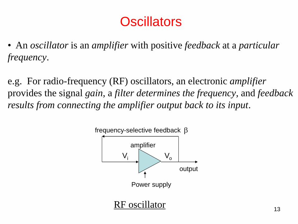
• An oscillator is an amplifier with positive feedback at a particular
frequency.
e.g. For radio-frequency (RF) oscillators, an electronic amplifier
provides the signal gain, a filter determines the frequency, and feedback
results from connecting the amplifier output back to its input.
frequency-selective feedback
amplifier
Power supply
output
RF oscillator
Vo Vi
b

14
Overall gain of the electronic oscillator
• The input and output voltages of the amplifier are Vi and Vo. The overall gain of the system is A, where A = Vo/Vi.
Vo = Ao(Vi + bVo)
=> Vo = AoVi / (1 – bAo)
And A = Ao / (1 – bAo)
• If bAo = +1 then the gain of the circuit would apparently become infinite, and the circuit would generate a finite output without any input.
• In practice electrical “noise,” which is a random oscillatory voltage generated to a greater or lesser extent in all electrical components in any amplifier system, provides a finite input. (Oscillators are “noise-start.”)
15
Oscillates by amplifying noise at specific frequencies
• Because bAo is generally a function of frequency the condition bAo = +1 is generally satisfied only at one frequency.
• The circuit oscillates at this frequency by amplifying noise at this same frequency that appears at its input.
• However, the output does not grow infinitely large, because as the signal grows, Ao falls --- this process is called saturation.
• This phenomenon is fundamental to all oscillator systems.
16
Laser is an optical-frequency oscillator
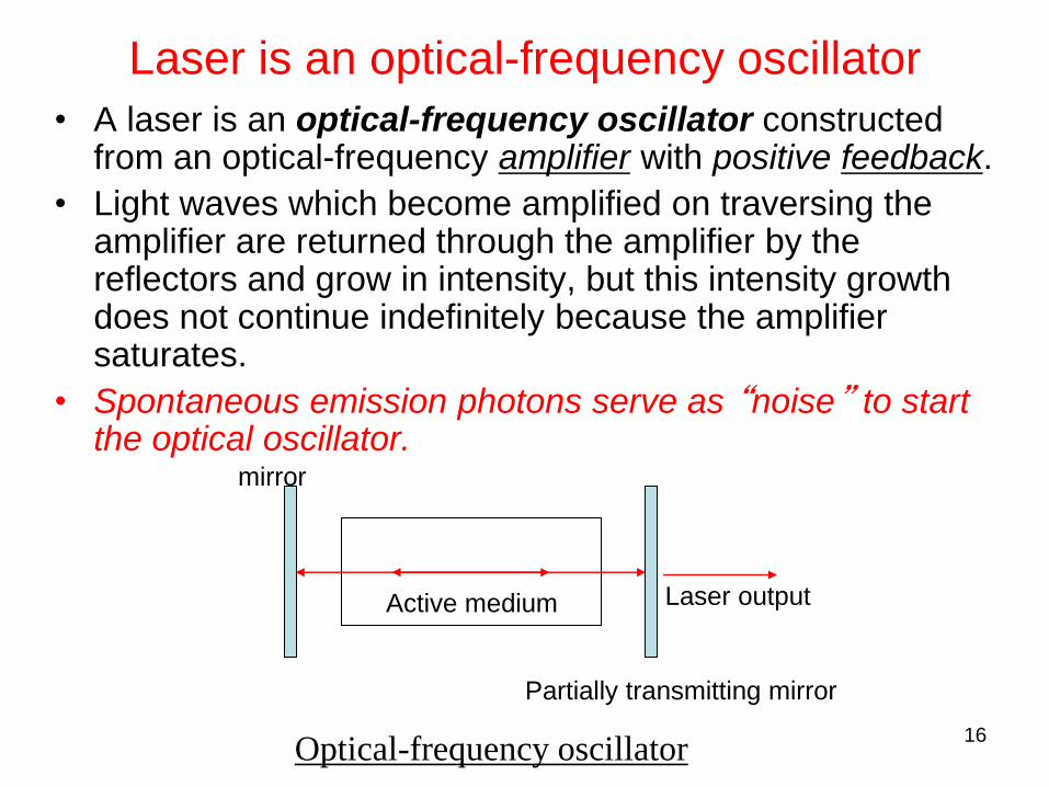
• A laser is an optical-frequency oscillator constructed from an optical-frequency amplifier with positive feedback.
• Light waves which become amplified on traversing the amplifier are returned through the amplifier by the reflectors and grow in intensity, but this intensity growth does not continue indefinitely because the amplifier saturates.
• Spontaneous emission photons serve as “noise” to start the optical oscillator.
mirror
Active medium
Partially transmitting mirror
Laser output
Optical-frequency oscillator

17
• In the case of the laser, the “gain” medium provides the light
amplification by stimulated emission.
• The gain medium also determines the frequency. It does so through its
characteristic energy levels and transitions between levels.
• Mirrors provide the feedback. Photons bounce off the mirrors and
return through the gain medium for further amplification. The resulting
standing waves favor the growth, and therefore oscillation, of cavity
resonance frequencies.
• One of the mirrors is partially transmitting to allow a fraction of the
generated light to output-couple. This results in coherent lasing emission.
Amplification, feedback and oscillation
18
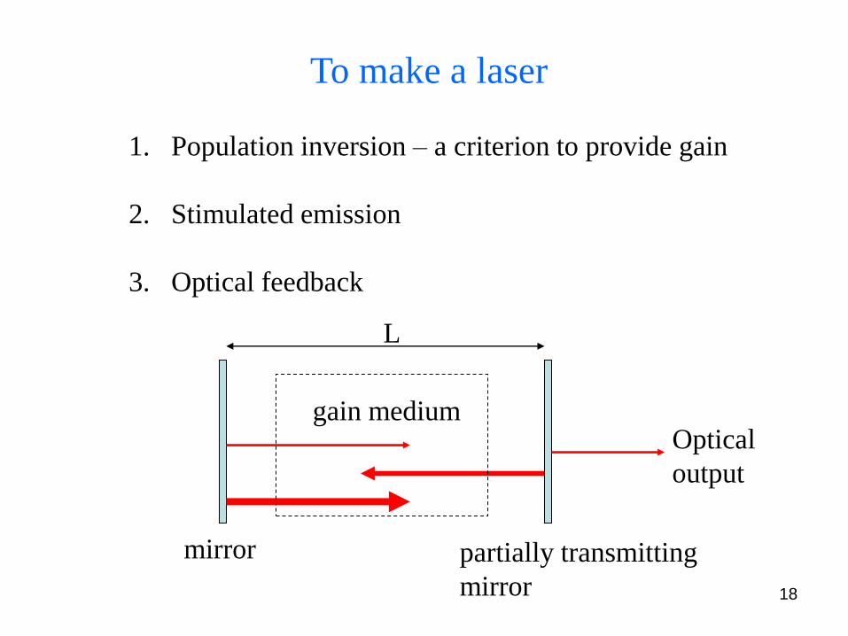
To make a laser
1. Population inversion – a criterion to provide gain
2. Stimulated emission
3. Optical feedback
mirror partially transmitting
mirror
L
gain medium Optical
output
19
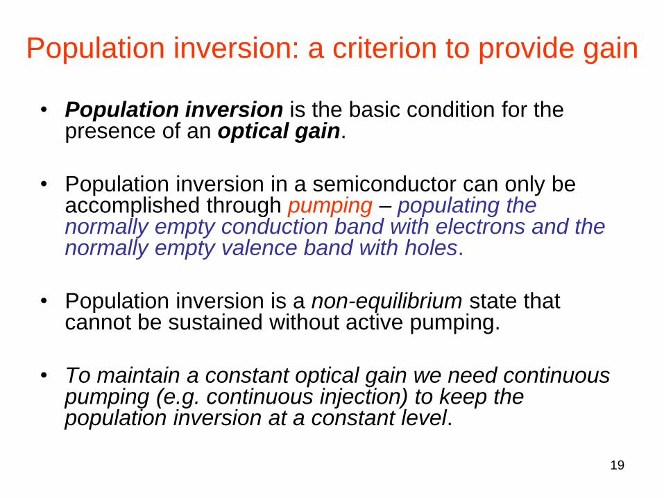
Population inversion: a criterion to provide gain
• Population inversion is the basic condition for the presence of an optical gain.
• Population inversion in a semiconductor can only be accomplished through pumping – populating the normally empty conduction band with electrons and the normally empty valence band with holes.
• Population inversion is a non-equilibrium state that cannot be sustained without active pumping.
• To maintain a constant optical gain we need continuous pumping (e.g. continuous injection) to keep the population inversion at a constant level.
20
Conditions for laser oscillation
• Two conditions must be satisfied for the laser to oscillate
(lase):
– The gain condition determines the minimum
population difference, and thus the pumping threshold
required for lasing
– The phase condition determines the frequency (or
frequencies) at which oscillation takes place

21
To achieve “lasing,” we need: 1. optical gain, and 2. optical feedback
• Optical gain makes an optical amplifier (usually broadband).
• Optical feedback (frequency selective) converts an amplifier into
an oscillator.
Amplifier vs. Oscillator
wavelength
Semiconductor
optical amplifier
(broadband,
~30 – 50 nm)
Oscillator (narrow band, ~ nm –
sub-nm)
*Linewidth narrowing is one key
signature of oscillation
22
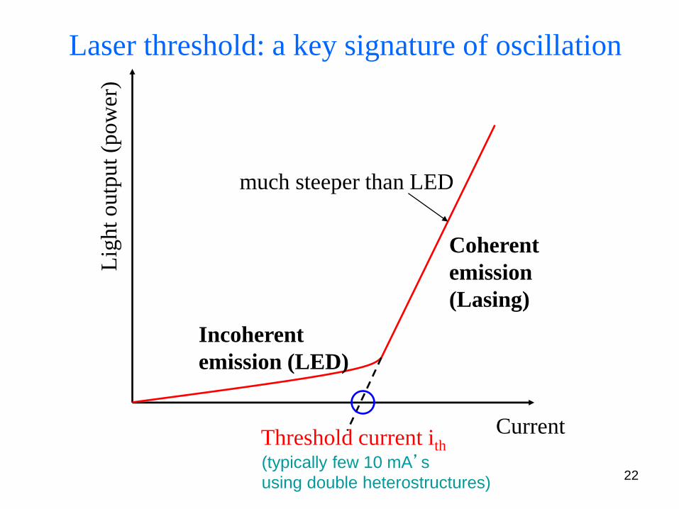
Laser threshold: a key signature of oscillation
Lig
ht
outp
ut
(pow
er)
Current
Incoherent
emission (LED)
Coherent
emission
(Lasing)
Threshold current ith
much steeper than LED
(typically few 10 mA’s
using double heterostructures)
23
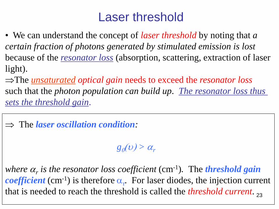
Laser threshold
• We can understand the concept of laser threshold by noting that a
certain fraction of photons generated by stimulated emission is lost
because of the resonator loss (absorption, scattering, extraction of laser
light).
The unsaturated optical gain needs to exceed the resonator loss
such that the photon population can build up. The resonator loss thus
sets the threshold gain.
The laser oscillation condition:
g0(u) > ar
where ar is the resonator loss coefficient (cm-1). The threshold gain
coefficient (cm-1) is therefore ar. For laser diodes, the injection current
that is needed to reach the threshold is called the threshold current.
24
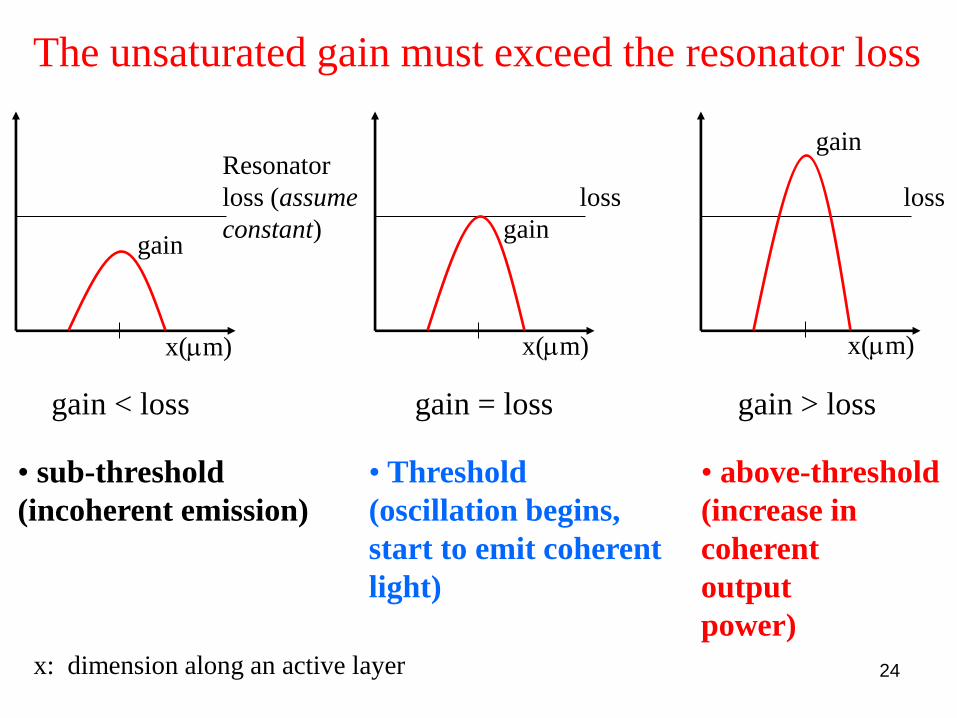
The unsaturated gain must exceed the resonator loss
• sub-threshold
(incoherent emission)
• Threshold
(oscillation begins,
start to emit coherent
light)
• above-threshold
(increase in
coherent
output
power)
Resonator
loss (assume
constant) gain
x(mm) x(mm) x(mm)
x: dimension along an active layer
gain < loss gain = loss
loss loss
gain > loss
gain
gain
25
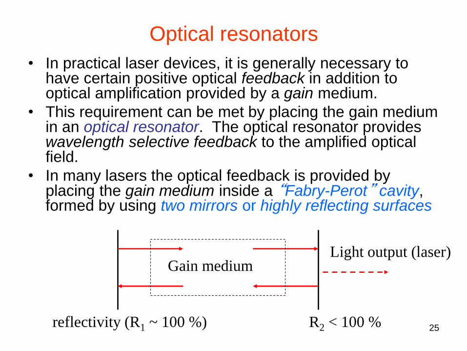
Optical resonators
• In practical laser devices, it is generally necessary to have certain positive optical feedback in addition to optical amplification provided by a gain medium.
• This requirement can be met by placing the gain medium in an optical resonator. The optical resonator provides wavelength selective feedback to the amplified optical field.
• In many lasers the optical feedback is provided by placing the gain medium inside a “Fabry-Perot” cavity, formed by using two mirrors or highly reflecting surfaces
reflectivity (R1 ~ 100 %) R2 < 100 %
Gain medium Light output (laser)
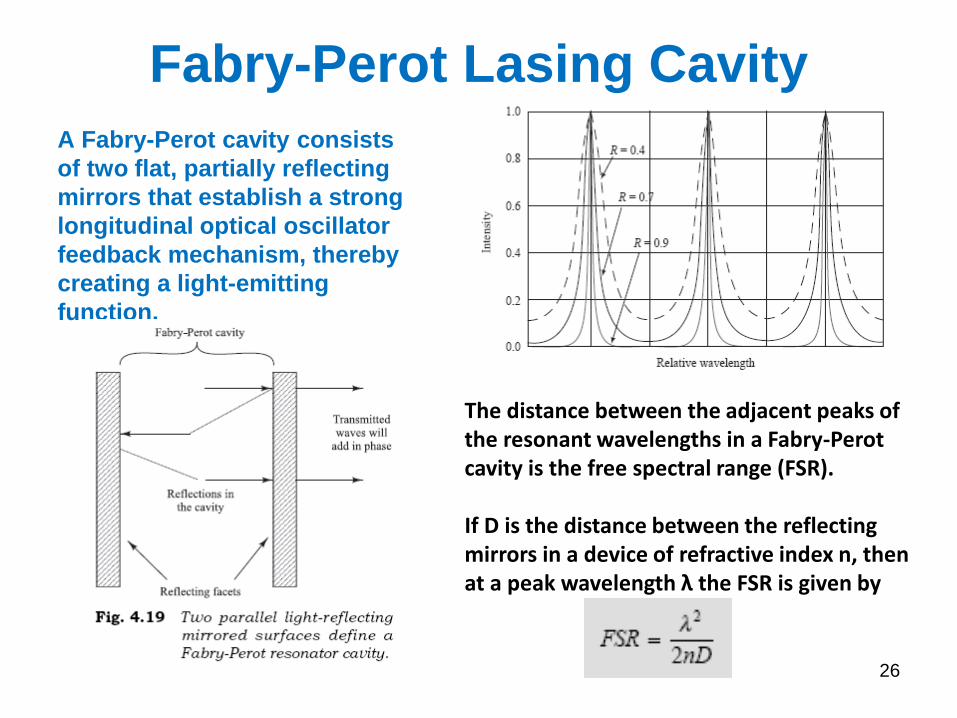
Fabry-Perot Lasing Cavity
A Fabry-Perot cavity consists
of two flat, partially reflecting
mirrors that establish a strong
longitudinal optical oscillator
feedback mechanism, thereby
creating a light-emitting
function.
26
The distance between the adjacent peaks of the resonant wavelengths in a Fabry-Perot cavity is the free spectral range (FSR). If D is the distance between the reflecting mirrors in a device of refractive index n, then at a peak wavelength λ the FSR is given by
27
R1 R2
Pout
R1
R2
Pout
Pout
Pout Pout Pout
Pout Pout
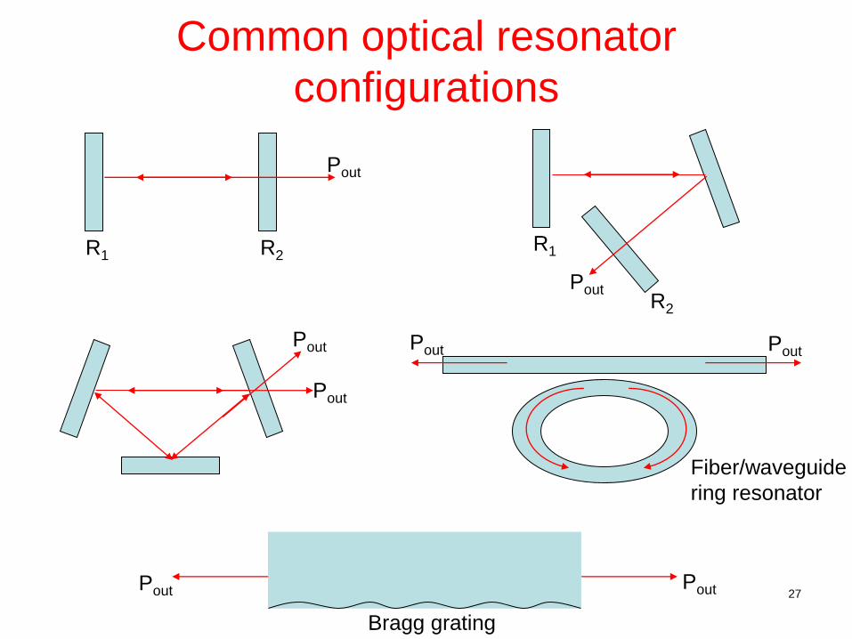
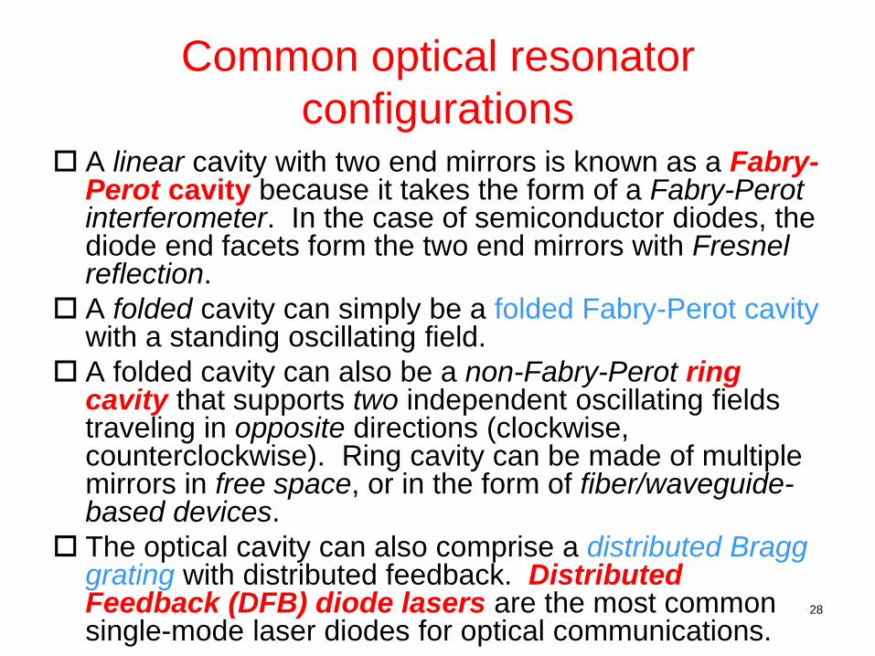
Common optical resonator
configurations
Bragg grating
Fiber/waveguide
ring resonator
28
A linear cavity with two end mirrors is known as a Fabry-Perot cavity because it takes the form of a Fabry-Perot interferometer. In the case of semiconductor diodes, the diode end facets form the two end mirrors with Fresnel reflection.
A folded cavity can simply be a folded Fabry-Perot cavity with a standing oscillating field.
A folded cavity can also be a non-Fabry-Perot ring cavity that supports two independent oscillating fields traveling in opposite directions (clockwise, counterclockwise). Ring cavity can be made of multiple mirrors in free space, or in the form of fiber/waveguide-based devices.
The optical cavity can also comprise a distributed Bragg grating with distributed feedback. Distributed Feedback (DFB) diode lasers are the most common single-mode laser diodes for optical communications.
Common optical resonator
configurations
29
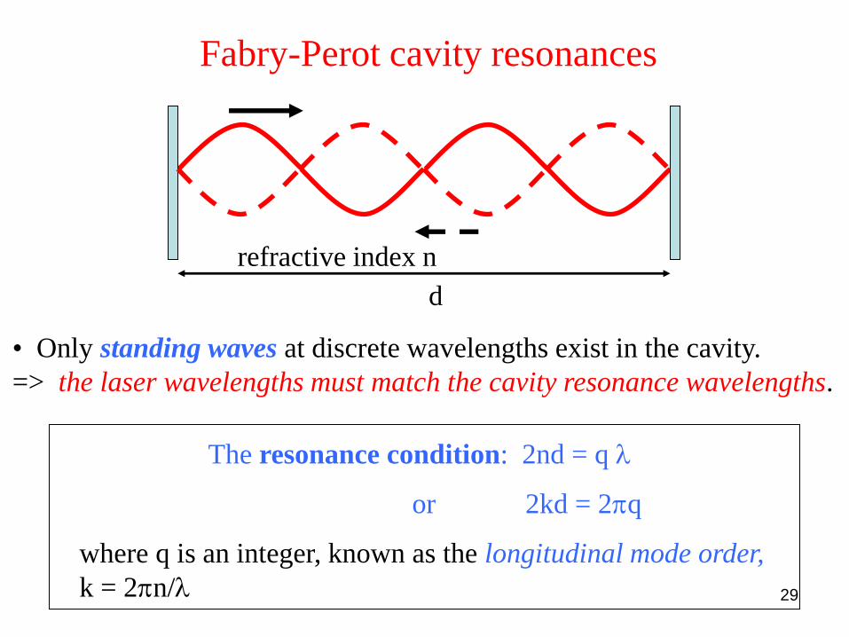
Fabry-Perot cavity resonances
• Only standing waves at discrete wavelengths exist in the cavity.
=> the laser wavelengths must match the cavity resonance wavelengths.
The resonance condition: 2nd = q l
where q is an integer, known as the longitudinal mode order,
k = 2pn/l
d
refractive index n
or 2kd = 2pq
30
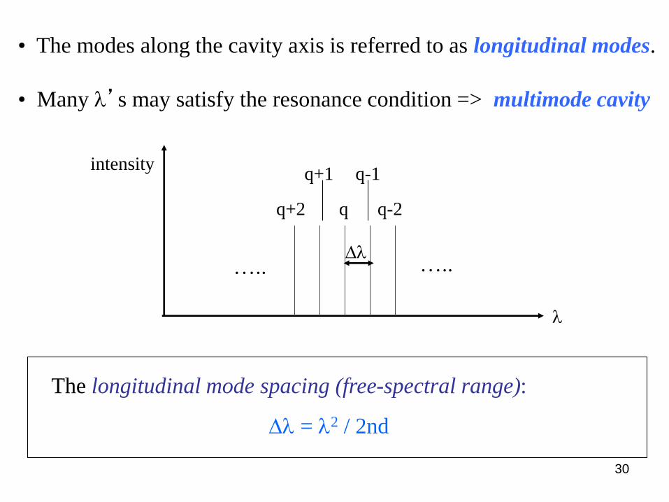
• The modes along the cavity axis is referred to as longitudinal modes.
• Many l’s may satisfy the resonance condition => multimode cavity
The longitudinal mode spacing (free-spectral range):
Dl = l2 / 2nd
l
intensity
q q-2 q+2
Dl
q+1 q-1
….. …..

31
e.g. A semiconductor laser diode has a cavity length 400 mm
with a refractive index of 3.5. The peak emission wavelength from
the device is 0.8 mm. Determine the longitudinal mode order
and the frequency spacing of the neighboring modes.
• The longitudinal mode order q = 2nd/l ~ 3500
• The frequency spacing Du = c/2nd ~ 100 GHz
• The longitudinal mode frequencies:
u = uq = qc/2nd
• The mode spacing (free-spectral range) in frequency unit:
Du = c/2nd

32
Resonator loss • The resonator contributes to losses. Absorption and
scattering of light in the gain medium introduces a power loss per unit length (attenuation coefficient as in cm-1)
• In traveling a round trip through a resonator of length L, the photon-flux density f is reduced by the factor
R1R2 exp(-2asL)
where R1 and R2 are the reflectances of the two mirrors
• The overall power loss in one round trip can be described by a total effective resonator loss coefficient ar in cm-1
exp(-2arL) = R1R2exp(-2asL)

33
Loss coefficients
ar = as + am1 + am2
am1 = (1/2L) ln(1/R1)
am2 = (1/2L) ln(1/R2)
where am1 and am2 represent the contributions of mirrors 1 and 2. (i.e. assuming the lumped mirror loss is distributed over a cavity round-trip length of 2L)
• The contribution from both mirrors
am = am1 + am2 = (1/2L) ln(1/(R1R2))
We can consider
34
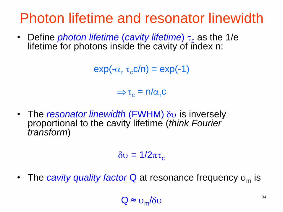
Photon lifetime and resonator linewidth
• Define photon lifetime (cavity lifetime) tc as the 1/e lifetime for photons inside the cavity of index n:
exp(-ar tcc/n) = exp(-1)
tc = n/arc
• The resonator linewidth (FWHM) du is inversely proportional to the cavity lifetime (think Fourier transform)
du = 1/2ptc
• The cavity quality factor Q at resonance frequency um is
Q ≈ um/du

35
• The finesse of the resonator
F ≈ Du/du
• When the resonator losses are small and the finesse is large
F ≈ p/(arL)
du
um-1 um
um+1 u
Du = c/2nL
Finesse of the resonator
36
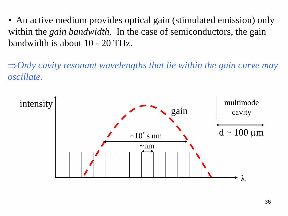
• An active medium provides optical gain (stimulated emission) only
within the gain bandwidth. In the case of semiconductors, the gain
bandwidth is about 10 - 20 THz.
Only cavity resonant wavelengths that lie within the gain curve may
oscillate.
l
intensity gain
d ~ 100 mm
multimode
cavity
~nm
~10’s nm

37
Loss ar
u Allowed
modes
u Resonator
modes
B u
Du
g0(u)
• Laser oscillation can occur only at frequencies for which the
unsaturated gain coefficient exceeds the resonator loss
coefficient.
Only a finite number of oscillation frequencies (u1, u2,…, um)
are possible.
u1 u3
u2
38
Laser modes
• The number of possible laser modes
M ≈ B/Du
• However, of these M possible modes, the number of modes that actually carry optical power depends on the nature of the spectral lineshape broadening mechanism.
• For a homogeneously broadened medium (e.g. semiconductor) these modes compete, rendering fewer modes (ideally single mode) to oscillate.
• For an inhomogeneously broadened medium (e.g. HeNe gas, Er3+-doped glass) all M modes may oscillate (albeit at different powers).
39
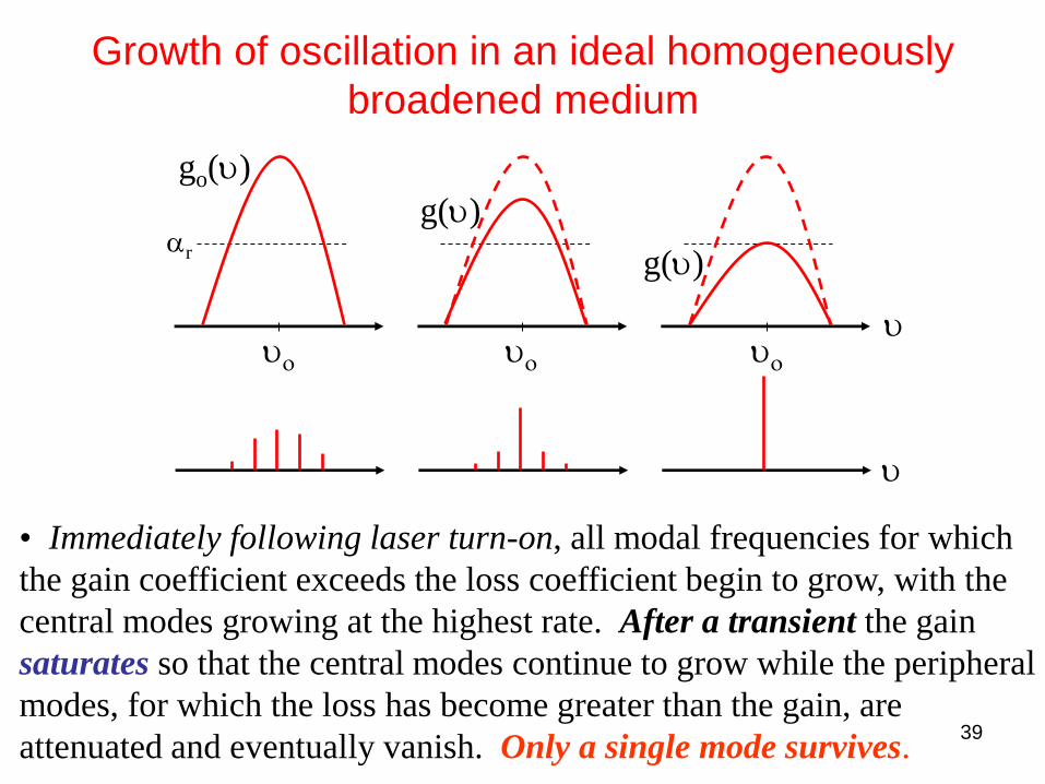
Growth of oscillation in an ideal homogeneously
broadened medium
ar
go(u)
g(u)
g(u)
uo uo uo
• Immediately following laser turn-on, all modal frequencies for which
the gain coefficient exceeds the loss coefficient begin to grow, with the
central modes growing at the highest rate. After a transient the gain
saturates so that the central modes continue to grow while the peripheral
modes, for which the loss has become greater than the gain, are
attenuated and eventually vanish. Only a single mode survives.
u
u

40
Gain and loss profiles in semiconductor lasers
The saturated gain of the longitudinal mode near to the gain peak
equals the loss.
frequency
saturated gain g (cm-1)
Loss ar (cm-1)
Longitudinal
modes uq
Lasing
mode
41
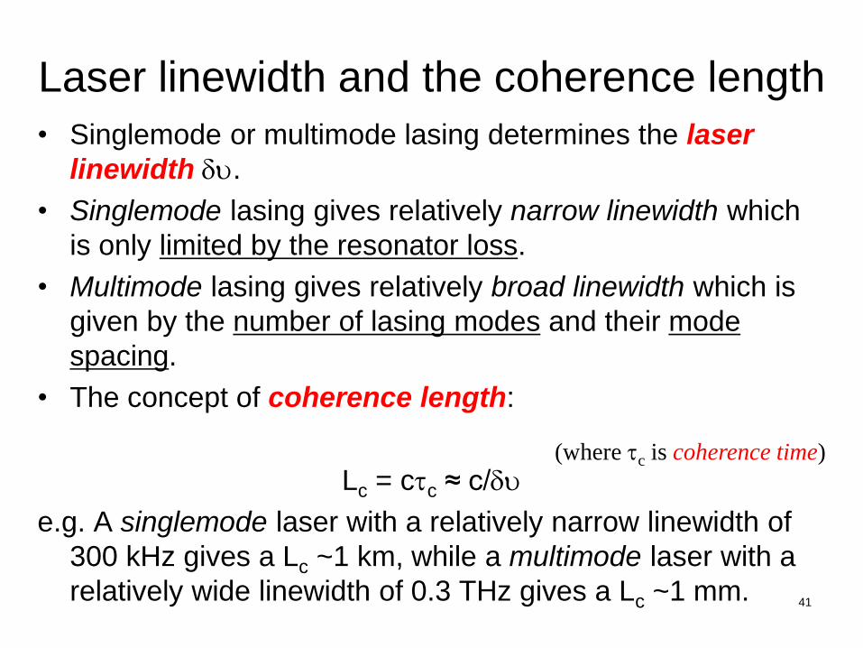
Laser linewidth and the coherence length
• Singlemode or multimode lasing determines the laser
linewidth du.
• Singlemode lasing gives relatively narrow linewidth which
is only limited by the resonator loss.
• Multimode lasing gives relatively broad linewidth which is
given by the number of lasing modes and their mode
spacing.
• The concept of coherence length:
Lc = ctc ≈ c/du
e.g. A singlemode laser with a relatively narrow linewidth of
300 kHz gives a Lc ~1 km, while a multimode laser with a
relatively wide linewidth of 0.3 THz gives a Lc ~1 mm.
(where tc is coherence time)
42
Gain saturation
• In the case of injection diode lasers, when the laser current density is
increased above its threshold value (i.e. J > Jth), the peak gain coefficient
gp exceeds the loss coefficient ar. (more discussion in Lect. 13)
=> Stimulated emission then outweighs absorption and other resonator
losses so that oscillation begins and the photon flux f in the resonator
increases.
• However, saturation sets in as the photon flux becomes larger.
the population difference (initial injected carrier density) becomes
depleted.
=> The gain coefficient then decreases until it becomes equal to the loss
coefficient, whereupon steady state is reached.
43
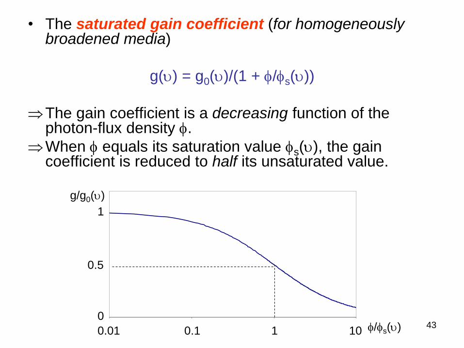
• The saturated gain coefficient (for homogeneously broadened media)
g(u) = g0(u)/(1 + f/fs(u))
The gain coefficient is a decreasing function of the photon-flux density f.
When f equals its saturation value fs(u), the gain coefficient is reduced to half its unsaturated value.
0.01 0.1 1 10
0.5
1
0 f/fs(u)
g/g0(u)
44
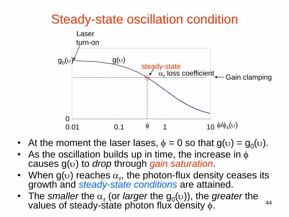
• At the moment the laser lases, f = 0 so that g(u) = g0(u).
• As the oscillation builds up in time, the increase in f causes g(u) to drop through gain saturation.
• When g(u) reaches ar, the photon-flux density ceases its growth and steady-state conditions are attained.
• The smaller the ar (or larger the g0(u)), the greater the values of steady-state photon flux density f.
0.01 0.1 1 10 0
f/fs(u)
g0(u) g(u)
Laser
turn-on
ar loss coefficient
f
steady-state
Steady-state oscillation condition
Gain clamping
45
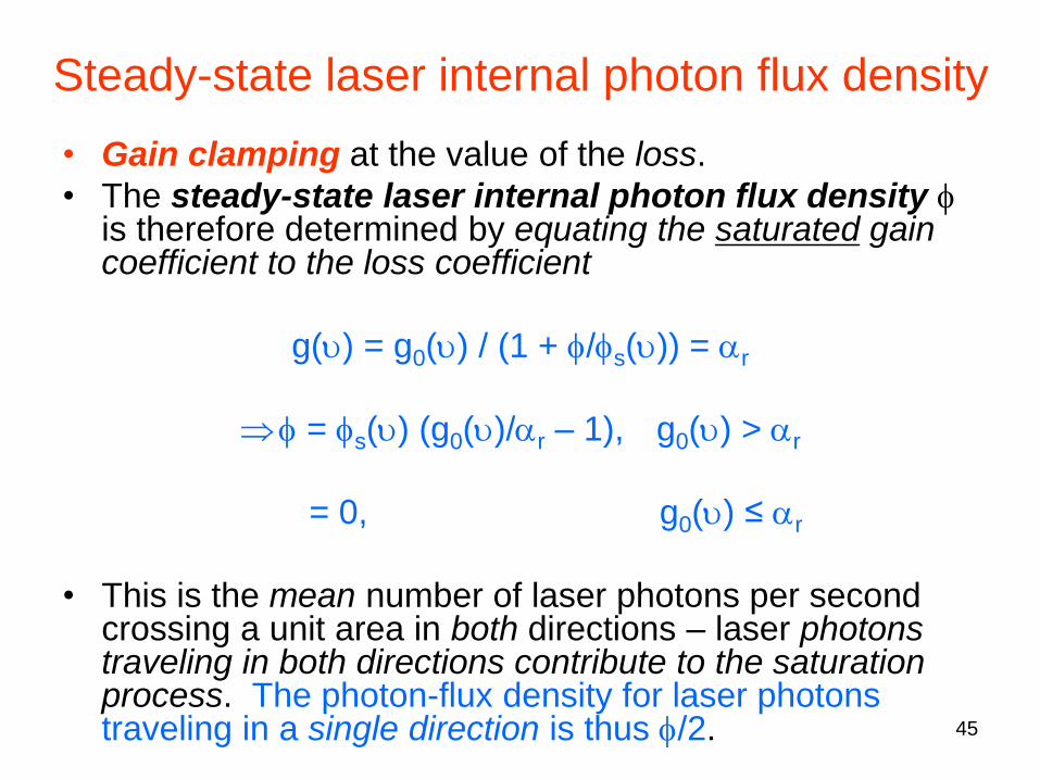
Steady-state laser internal photon flux density
• Gain clamping at the value of the loss.
• The steady-state laser internal photon flux density f is therefore determined by equating the saturated gain coefficient to the loss coefficient
g(u) = g0(u) / (1 + f/fs(u)) = ar
f = fs(u) (g0(u)/ar – 1), g0(u) > ar
= 0, g0(u) ≤ ar
• This is the mean number of laser photons per second crossing a unit area in both directions – laser photons traveling in both directions contribute to the saturation process. The photon-flux density for laser photons traveling in a single direction is thus f/2.
46
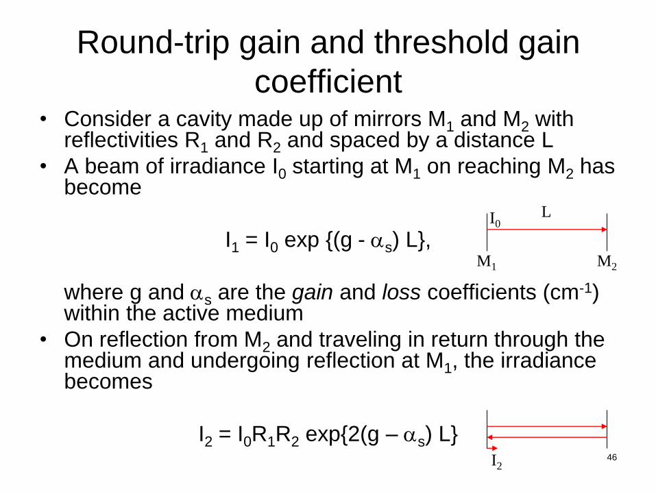
Round-trip gain and threshold gain
coefficient • Consider a cavity made up of mirrors M1 and M2 with
reflectivities R1 and R2 and spaced by a distance L
• A beam of irradiance I0 starting at M1 on reaching M2 has become
I1 = I0 exp {(g - as) L},
where g and as are the gain and loss coefficients (cm-1) within the active medium
• On reflection from M2 and traveling in return through the medium and undergoing reflection at M1, the irradiance becomes
I2 = I0R1R2 exp{2(g – as) L}
M1 M2
L I0
I2
47
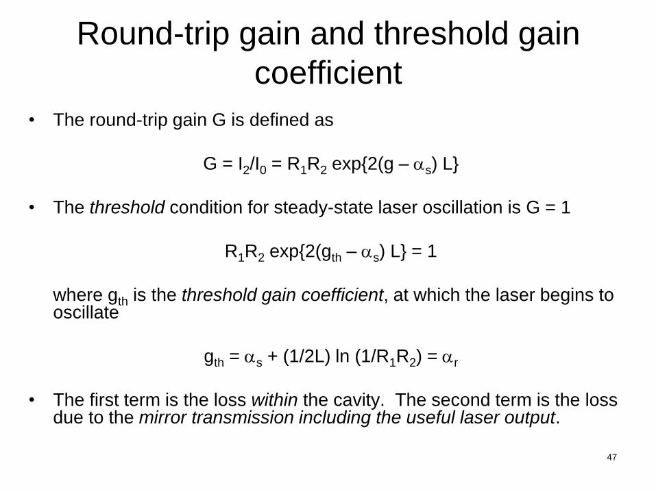
Round-trip gain and threshold gain
coefficient
• The round-trip gain G is defined as
G = I2/I0 = R1R2 exp{2(g – as) L}
• The threshold condition for steady-state laser oscillation is G = 1
R1R2 exp{2(gth – as) L} = 1
where gth is the threshold gain coefficient, at which the laser begins to oscillate
gth = as + (1/2L) ln (1/R1R2) = ar
• The first term is the loss within the cavity. The second term is the loss due to the mirror transmission including the useful laser output.
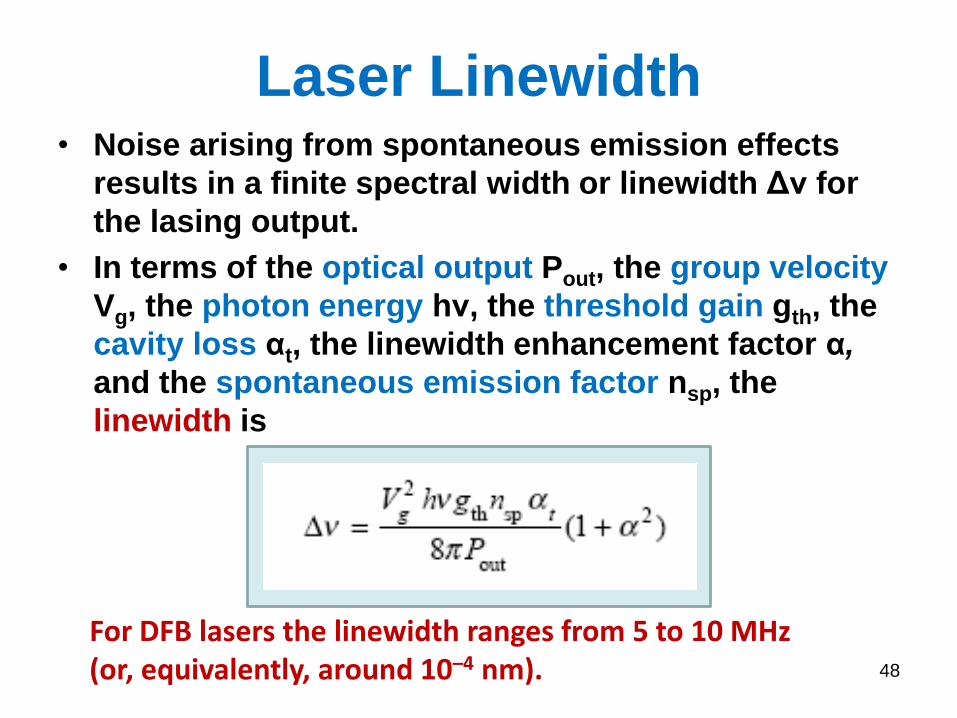
Laser Linewidth • Noise arising from spontaneous emission effects
results in a finite spectral width or linewidth Δν for
the lasing output.
• In terms of the optical output Pout, the group velocity
Vg, the photon energy hν, the threshold gain gth, the
cavity loss αt, the linewidth enhancement factor α,
and the spontaneous emission factor nsp, the
linewidth is
48
For DFB lasers the linewidth ranges from 5 to 10 MHz (or, equivalently, around 10–4 nm).
49
Summary: Conditions for laser oscillation
Two conditions must be satisfied for the laser to oscillate:
• The amplifier unsaturated gain must exceed the loss in the feedback
system so that net gain is incurred in a round trip through the feedback.
• The total phase shift in a single round trip must be a multiple of 2p so that the feedback input phase matches the phase of the original
input.
*As the power in the oscillator grows, the amplifier gain saturates.
A stable condition is reached when the reduced gain is equal to the
resonator loss. Steady-state oscillation then prevails.

50
Brief discussion on laser
systems
51
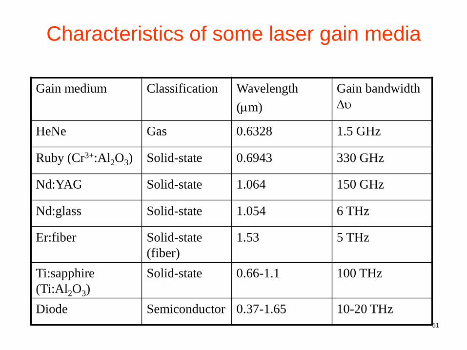
Characteristics of some laser gain media
Gain medium Classification Wavelength
(mm)
Gain bandwidth
Du
HeNe Gas 0.6328 1.5 GHz
Ruby (Cr3+:Al2O3) Solid-state 0.6943 330 GHz
Nd:YAG Solid-state 1.064 150 GHz
Nd:glass Solid-state 1.054 6 THz
Er:fiber Solid-state
(fiber)
1.53 5 THz
Ti:sapphire
(Ti:Al2O3)
Solid-state 0.66-1.1 100 THz
Diode Semiconductor 0.37-1.65 10-20 THz
52
Gas lasers
Gas lasers may be divided into atomic, ionic and
molecular, depending on the active amplifying
species in the gas
Generally gas lasers are excited by an electrical
discharge in which excitation of the gas atoms or
molecules is by collision with energetic electrons
Optical excitation of a gas is usually
inappropriate as the absorption lines of gases
are very narrow (in contrast to solids)
53
Example gas lasers: helium-neon
lasers
The helium-neon (HeNe) laser was the
first gas laser to be operated, and was the
first continuously operating laser
It is still one of the most common lasers,
operating on the 632.8 nm wavelength
Used in many applications requiring a
relatively low power, visible, continuous
and stable beam
54
Gas lasers
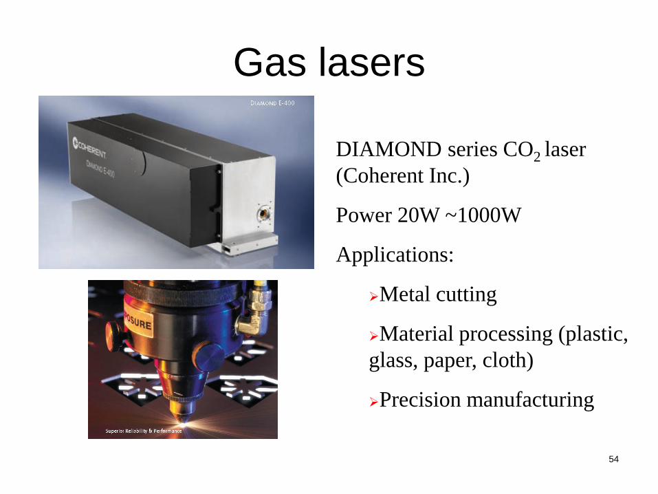
DIAMOND series CO2 laser
(Coherent Inc.)
Power 20W ~1000W
Applications:
Metal cutting
Material processing (plastic,
glass, paper, cloth)
Precision manufacturing

55
Solid-state lasers
A solid-state laser, such as the ruby laser, may be in the simple form of a transparent rod with mirrors formed directly on the ends
The gain medium contains active ions in a host crystalline solid or glass.
The active ions may be substituted into the crystal lattice or may be doped as an impurity into the glass host
There are many combinations of dopant ion and host materials which provide a wide range of laser wavelengths
The doped solids exhibit broad absorption bands which makes them amenable to optical excitation from continuous or pulsed lamps or from semiconductor diode lasers (known as diode-pumped solid state (DPSS) lasers, e.g. green laser pointers)

56
Doped medium
• The dopant ion should fit readily into the crystal host by matching the size and valency of the element for which it is substituting
• The optical quality of the doped medium should be high s.t. there is low loss for the amplifying beam
• Refractive index variations, scattering centers and absorption can contribute to loss processes
• Suitable host media are garnets (complex oxides), sapphire (Al2O3), aluminates and fluorides (e.g. Ti:Al2O3 lasers emitting in 800 nm range)
57
Dopant ions
The dopant ions are usually from the transition metals and lanthanide rare earths
The Nd:YAG laser operating at 1064 nm is one of the most used solid-state lasers
Neodymium ions Nd3+ provide the laser action, and yttrium aluminum garnet (YAG) is the usual crystal host
The crystal has a relatively high thermal conductivity which enables it to distribute heat efficiently following optical pumping.
The laser can operate either pulsed or continuously
58
Neodymium-doped glass
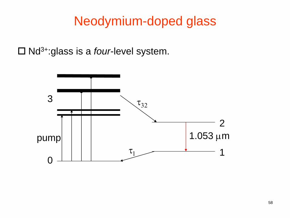
Nd3+:glass is a four-level system.
0
3
2
1
pump
t32
t1
1.053 mm
59
Solid-state lasers
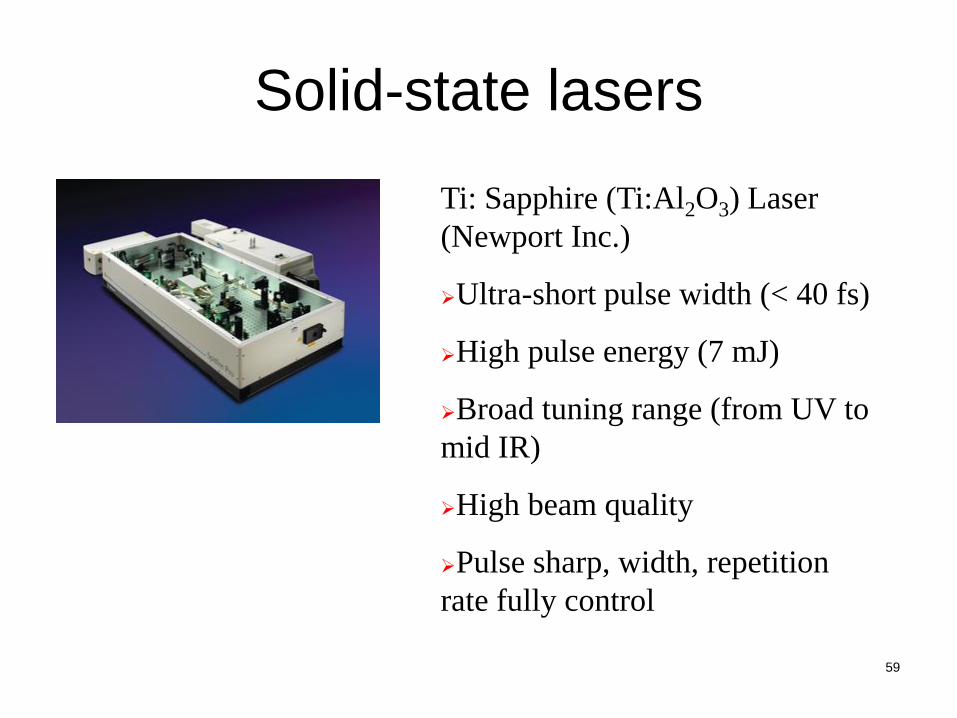
Ti: Sapphire (Ti:Al2O3) Laser
(Newport Inc.)
Ultra-short pulse width (< 40 fs)
High pulse energy (7 mJ)
Broad tuning range (from UV to
mid IR)
High beam quality
Pulse sharp, width, repetition
rate fully control
60
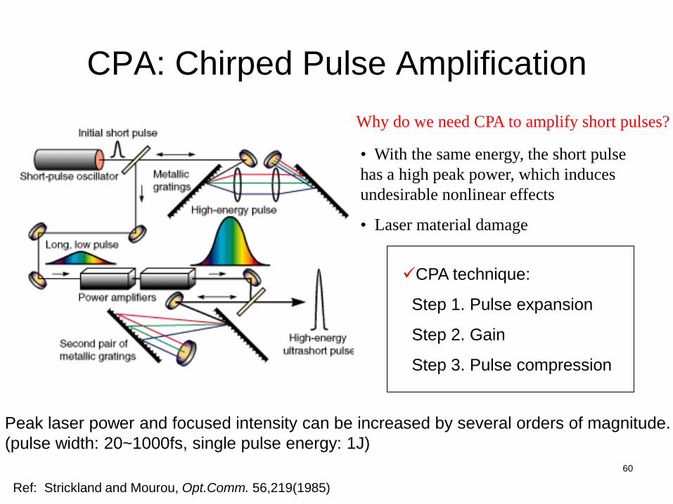
CPA: Chirped Pulse Amplification
Ref: Strickland and Mourou, Opt.Comm. 56,219(1985)
• With the same energy, the short pulse
has a high peak power, which induces
undesirable nonlinear effects
• Laser material damage
CPA technique:
Step 1. Pulse expansion
Step 2. Gain
Step 3. Pulse compression
Peak laser power and focused intensity can be increased by several orders of magnitude.
(pulse width: 20~1000fs, single pulse energy: 1J)
Why do we need CPA to amplify short pulses?

61
Fiber lasers
Usually pumped by a laser diode
Simple structures, low cost,
portable
Gain medium: rare-earth doped
fiber Erbium (Er), Ytterbium (Yb)
and Holmium (Ho) and so on.
Photonic crystal fiber laser
(“Supercontinuum” emitted from a fiber laser)

62
Fiber laser
• Fiber laser is one example of solid-state lasers
• Active ion is distributed throughout a long silica fiber
• The core of the silica fiber, which is several meters long and has resonator mirrors at each end, is doped with rare-earth ions (e.g. erbium Er3+ for 1.55 mm, ytterbium Yb3+ or neodymium Nd3+ for 1.06 mm, thulium for 2 mm)
• The pump is a semiconductor diode laser array (at a shorter wavelength than the fiber laser wavelength) focused on one fiber end
• Fiber laser can output few – kilo Watts
63
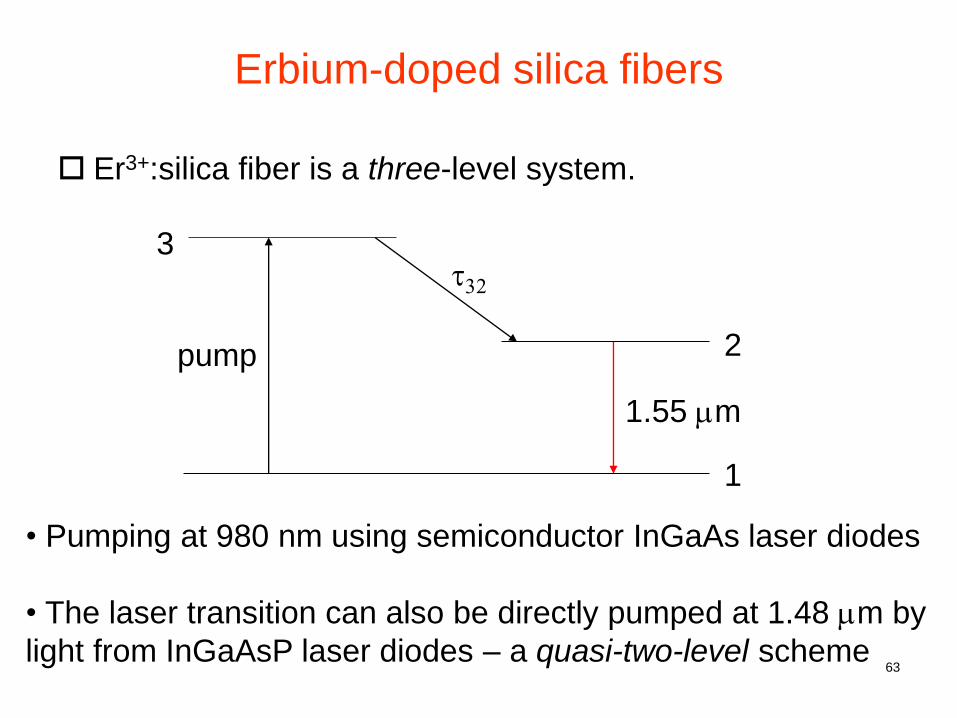
Erbium-doped silica fibers
Er3+:silica fiber is a three-level system.
3
2
1
pump
t32
1.55 mm
• Pumping at 980 nm using semiconductor InGaAs laser diodes
• The laser transition can also be directly pumped at 1.48 mm by
light from InGaAsP laser diodes – a quasi-two-level scheme
64
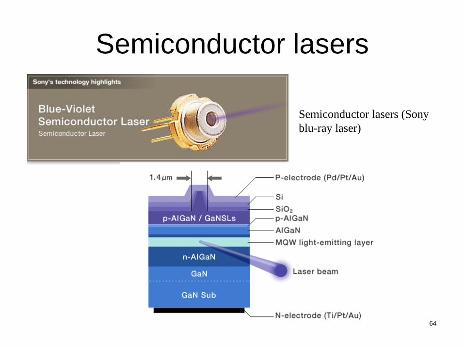
Semiconductor lasers
Semiconductor lasers (Sony
blu-ray laser)
65
Semiconductor lasers Semiconductor lasers are distinct from the solid-state
lasers in their pumping and photon generation processes.
They derive their energy from the electrical excitation of electrons within the semiconductor.
The lasers are essentially diodes so they are electrically pumped and compact.
Different laser lines can be generated by using different semiconductor gain media (e.g. GaN-based for blue light, GaAs-based for near-IR, InP-based for 1.55 mm telecom. wavelengths, etc.)
Some semiconductor lasers can generate high power (e.g. Spectra Physics ~kW continuous-wave per chip) for pumping other lasers such as solid-state lasers / fiber lasers.
We will see in Lecture 13 that semiconductor diode lasers have a lot in common with light-emitting diodes (LEDs).
66
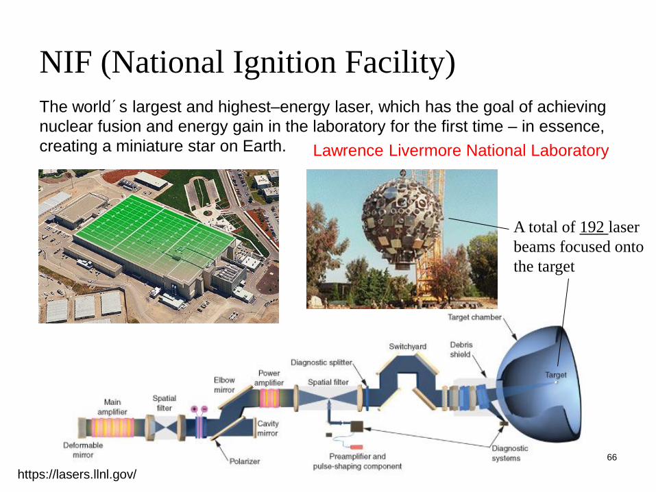
NIF (National Ignition Facility)
The world´s largest and highest–energy laser, which has the goal of achieving
nuclear fusion and energy gain in the laboratory for the first time – in essence,
creating a miniature star on Earth. Lawrence Livermore National Laboratory
https://lasers.llnl.gov/
A total of 192 laser
beams focused onto
the target
67
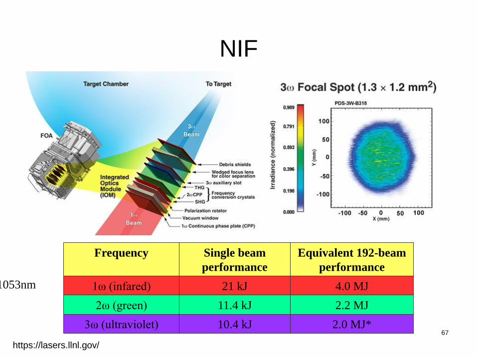
NIF
Frequency Single beam
performance
Equivalent 192-beam
performance
1ω (infared) 21 kJ 4.0 MJ
2ω (green) 11.4 kJ 2.2 MJ
3ω (ultraviolet) 10.4 kJ 2.0 MJ*
https://lasers.llnl.gov/
1053nm