Embed Size (px)
Citation preview

1
LENNOX RESIDENTIAL COMMUNICATING SYSTEMS SERVICE MANUAL
Parameters and Error Codes-Troubleshooting for Communicating Thermostats, Indoor and Outdoor Units, iHarmony, Equipment Interface Module and PureAir S
Corp1817-L8 3/2021
Table of Contents1. Firmware Version ................................................................... 22. Equipment Parameters .......................................................... 2
2.1. Smart Hub ........................................................................................... 22.2. Heat Pumps ...................................................................................... 142.3. Air Conditioners ................................................................................. 162.4. Air Handlers ...................................................................................... 172.5. Furnaces ........................................................................................... 182.6. Zoning ............................................................................................... 202.7. Thermostat - HD display ................................................................... 202.8. Thermostat - Mag Mount (Used with Display 1.0 and 2.0 Only) ....... 202.9. PureAir S ........................................................................................... 212.10. Thermostat Utilities ........................................................................... 21
3. Communicating Alert Codes, Soft Disable, Inverter Codes/LEDs and Troubleshooting ...................................... 223.1. Alert Code Types ............................................................................... 223.2. Soft Disable ....................................................................................... 223.3. Inverter LED Normal Operations Indicators ...................................... 223.4. E30 and S30 (Second and Third Generation) LED Indicators .......... 233.5. S30 (First Generation) LED Indicators .............................................. 243.6. S30 (First Generation) Center Push Button Indicator ....................... 253.7. Alert Codes ....................................................................................... 26
4. ServiceNotificationCodes .................................................. 755. Electrical Troubleshooting .................................................. 75
5.1. Overview ........................................................................................... 755.2. Definitions ......................................................................................... 755.3. iComfort® S30 (Smart Hub 1.0).......................................................... 765.4. iComfort® S30 (Smart Hub 2.0 and 3.0)............................................. 775.5. iComfort® E30 (Smart Hub 1.0 and 2.0) ............................................ 785.6. Lennox Communicating Indoor / Outdoor Units and Equipment
Interface Module ............................................................................... 796. Thermostat Wiring Termination in Communicating
System ................................................................................... 807. Wiring Type Requirements .................................................. 818. Change Log ........................................................................... 87
PureAir S
iHarmony (Damper Control Module and Zone
Sensor)
Lennox Communicating Air Handlers
Lennox Communicating Furnaces
Lennox Communicating Outdoor Units
Mag-Mount for First and
Second generation HD displays only)
HD display (First, Second
and Third Generation)
S30 Smart Hub (Second & Third
Generation)
S30 Smart Hub (First
Generation)
NOTE: There are parameters listed for various Lennox products that are supported by our communication systems (ie, iComfort E30, dehumidification, humidification and ERV/HRV.

2
1. Firmware VersionThe contents of this service document includes changes implement up to thermostat and smart hub control software version 03.60.xxxx.2. Equipment ParametersSelectionslistedinthissectionaredependentonsystemhardwareconfiguration.Notalloptionslistedinthissectionwillbeavailable.NOTE: When changing the default settings for any parameter, there is a possibility that it will affect the settings for another parameter. If this happens, a pop-up
message will be displayed listing the other affected parameters and their new automatically set values.
The following is a complete list of all possible parameters listed under System. Parameters actually available are dependent on the Lennox communicating equipment type detected and non-communicating equipment added.
2.1. Smart Hub
Table 1. Smart Hub ParametersParameter Description
AboutThis screen provides information concerning language supported, equipment type name, control software revision, model, control mode number, control serial number, control hardware revision, protocol revision number, device product level, 24VAC average power consumption, 24VAC peak power consumption, compatible devices list, application code memory size and micro-controller part number.
Auto Changeover - Humidif. Deadband
Preventsthehumidificationanddehumidificationsettingsfrombeingclosertogetherthan5%orgreaterthan10%(dead-band).
Rangeis5to10%.Defaultis5%.Adjustmentsareinincrementsof1%.
Auto Changeover - Temp Deadband
Prevents the Heating and Cooling from being set closer together than 3ºF (1.67°C) or greater than 9ºF (5.0°C) (dead- band).
Rangeis3to9°F(1.67to5.0°C).Defaultis3°F(1.67°C).Adjustmentsareinincrementsof1°F(0.56°C).
AutoDehumidificationOvercooling Threshold
Thisvaluecanautomaticallybeaffectedbyadjustingotherparameters.OneexamplewouldbewhenenablingMaxDehumidificationOvercooling.
Rangeis0-10%.Defaultis4%.Adjustmentsareinincrementsof1%.
Aux Heating Activation Threshold
Thisisanadjustmenttohastenordelaytheauxiliaryheatactivation.Thisadjustshowfarbelowthesetpointthetemperaturemustfallwiththeheatpumpat100%before allowing electric heat to come on.
Range is 0 - 10°F (0.0 to 5.56°C) with increments of 0.25°F (0.14°C). The default setting is 2.5°F (1.39°C).
Definition/Dependencies:Step Change versus Steady State Modes
• Outdoor temperature below the high balance point or with balance points disabled.• HeatPumpdemandabove95%for10minutes.• Sixty (60) minute temperature rise prediction = less than this Parameter Setting (value)Result:The Heating Proportional Integral Algorithm (set for either less, normal, or more aggressive) will begin to stage on the electric heat to bring the space temperature up to set point.
Synopsis: The lower this parameter is set, the quicker the auxiliary heating will respond, in both step-change and steady-state modes.
NOTE: Staged heating will stage by the differential setting.

3
Table 1. Smart Hub ParametersParameter DescriptionBalance Point ControlIf system is set up as dual fuel or heat pump with electric heat and a outdoor temperature sensor connected to smart hub, the low and high balance point settings will appear. The balance points feature requires that a s ensed outdoor temperature is provided to the thermostat. The outdoor ambient temperature can be read from either a:
• Field-installed outdoor temperature sensor (X2658).• Communicating heat pump. All communicating heat pumps have a factory-installed outdoor temperature sensor.Options are enabled or disabled. Default is disabled. When enabled, both low and high balance points can be set.
The high and low balance points will affect the upstaging of the thermostat.
NOTE: Internet temperatures are not used in balance point.
High Balance Point
Thissettingisusedtopreventthefurnaceorelectricheatfromoverheatingthestructure.(Alert19-Minor-Notificationonly-Theoutdoortemperatureishigherthanthe level where the furnace or electric heat is programmed to heat the home.)
Second-stage heating will not turn on unless the temperature falls below the high balance point setting.
Rangeis-17to75°F(-27.22to23.89°C).Defaultis50°F(10.0°C).Adjustmentsareinincrementsof1°F(0.56°C).
Low Balance Point
Settingusedtopreventtheheatpumpfromheatingthestructure.(Alert18-Minor-Notificationonly-Theoutdoortemperatureisbelowthelevelwheretheheatpumpis programmed to heat the home).
Rangeis-20to72°F(-28.89to22.22°C).Defaultis25°F(-3.89°C).Adjustmentsareinincrementsof1°F(0.56°C).
First-stage heating will not activate if the temperature falls below the low balance point setting.
NOTE: Dual-Fuel Applications (Communicating Systems Only) - Dual fuel applications, which include both a Heat Pump and a gas furnace, will provide multiple stages of heating. For example, a two−stage heat pump would deliver two stages of heat. The gas furnace can add two to four more stages of heat.
Cooling Discomfort Threshold
Default is ON. The purpose of this algorithm when set to ON is to detect systems with faults which are causing measurable loss of comfort and thus, need repair/service intervention.
The algorithm monitors the duration in which the indoor temperature is above the cool set point or below the heat set point and does not approach the set-point. When an issue is detected alert code 901 is activated.
Cooling Capacity AlertOptionsareONorOFF.DefaultisON.Coolingoperationmaynotbesufficientforthehottestdays.Basedonlocalconditionsandclimatologicaldataforzipcode.
Examples: Dirty Filter, Low Refrigerant charge, TXV, etc. Symptom during mild temperatures may include; system running longer than normal but not showing any other symptoms.
Cooling Mode(For multi-staged equipment only)
OptionsareNormalandComfort.DefaultisNormal.WhenchangingtoComfortMode,severalparametersareautomaticallymodifiedforoptimalsystemoperations.The changed parameters are listed on the screen when set to Comfort.
• Normal-Thissettingcoolsthehometothedesiredtemperaturesetting.Oncesecond-stageisactivatedbytimerordifferential,itwillnotstagedowntofirst-stageuntilthe next cooling cycle demand.
• Comfort - This is when the system could automatically stage up or down based on the current load demand.
Cooling Prognostics
This algorithm will determine whether the unit will run out of capacity during the hottest time of summer. It will look back everyday a minimum of three days to see if thereisapatternandcompareittothehottestdayonrecordforthatzipcodebeforetriggeringannotification.Itmustseeapatternbeforeitwilltriggerthenotification.There may be a component or components that will require attention.
The sensitivity (threshold) selection options are OFF, LOW, MEDIUM, and HIGH. The default is HIGH.Thealertcodenotificationis65545.
Discharge Air Temperature (DAT) Integral Gain(Lennox Variable Capacity Outdoor Units Only)
This indicates how stable the system is attempting to reach the discharge air temperature set point. You may hear the compressor hunting (ramping up and down) adjustingtolowersettingwillcorrect.
LennoxadvisesnottomakechangestothissettingwithoutfirstcontactingLennoxtechnicalsupportorLennoxfieldtechnicalconsultant.
Default is 3.0. Range is 1.0 to 15.0 in increments of 0.5.
DAT Offset This parameter is only available when a Lennox variable capacity outdoor units is installed along with a discharge air temperature sensor (DATS) unit.
Default is 0.0°F (0.0°C). Range is -5.0°F to 5.0°F (-2.78 to 2.78°C) in increments of 0.5°F (0.28°C).

4
Table 1. Smart Hub ParametersParameter Description
DAT Proportional Gain(Lennox Variable Capacity Outdoor Units Only)
This is how the system attempts to reach the discharge air temperature set point.
LennoxadvisesnottomakechangestothissettingwithoutfirstcontactingLennoxtechnicalsupportorLennoxfieldtechnicalconsultant.
Default is 3.0. Range is 1.0 to 15.0 in increments of 0.5.
Dew Point Adjustment
TheDewPointAdjustmentcanbesetfrom-15%to+15%.ThesesettingsallowadjustmentstotheDewPointsettingforthehome.Somehomesmayrequireanadjustmenttohelpmaintaincomfort.Ifcondensationispresentonwindows,settheadjustmentlower,between-15%to-5%.Ifthehomefeelsdry,settheadjustmentupwards,between+5to+15%.
NOTE: In this mode the RH set point is ignored.
Electric Heat Control Mode(Single and Two-Stage Lennox Communicating Outdoor Units Only)
In heat pump applications, the electric heat is staged to provide supplemental heat to meet desired comfort levels. When the electric heat section is used in applications that do not have a heat pump, the elements are staged to limit heat so that it meets heating demands only.
Options are Standard and Evenheat. Default is Standard.
Electric Heat Stages During Defrost
Can increase or decrease the number of electric elements to come on during a call for defrost. (Thermostat will have a demand for heat.)
Rangeis0to5electricheatstages.Defaultis2.Adjustmentsareinincrementsof1.
Electric Heating Activation Hold Time
This parameter represents the amount of time the system waits to check the slope of the temperature against the value in “Aux Heating Activation Threshold” parameter. It checks the room temperature slope after a time to determine if aux heat is needed to achieve a new room temperature set point) to allow the heating PI to accumulate past 100 (up to 200) which allows electric auxiliary heat use. Range is 0~60 minutes with a default of 10 minutes. Increments are in 5 minute intervals.
Electric Heating Activation Temp Difference
When the system is operating at full heat pump demand, this is the amount of °F (°C) below the set point that is allowed before allowing the use of Aux heat to supple-menttheheatpump.Thisparameterisonlyavailablewhenthesystemisconfiguredwithanairhandlerandvariablecapacityheatpump.
Range is 0.5 - 10ºF. Default 1.5ºF. Increment of 0.5ºF.
Equipment Name A unique name can be assigned to this component. Name can be up to 29 characters. Name can consist of letters, numbers, special characters and spaces.
EvenHeat Discharge Temp
When in EvenHeat control mode, the thermostat will stage the electric heat sections to maintain a constant discharge air temperature. The system must have a discharge air temperature sensor (DATS) connected to show this parameter.
NOTE: Not selectable on Lennox variable capacity outdoor units. Electric heat elements will be staged on by the demand of the thermostat.
Rangeis85to130ºF(29.4to54.4ºC).Defaultis85ºF(29.4ºC).Adjustmentscanbemadeinincrementsof15ºF(8.4ºC).
Gas Heat Control Mode (SLP98 only)
Options are Staged, Load Tracking Variable Capacity and Variable Capacity. Default is Load Tracking Variable Capacity
Staged:Somefurnacescanbeconfiguredtoprovideuptofourstagesofgasheatoperation.Whenstagedheatingischosen,theiComfortcommunicatingthermostatallowsyoutochoosebetween1,2,3and4stagesofheat.Single-stageheat:firststageprovides100%offullcapacity.
• Two-stageheat:Firststageprovides70%offullcapacity;2ndstageprovides100%offullcapacity.• Three-stage heat:Firststageprovides60%offullcapacity;2ndstageprovides80%offullcapacity;thirdstageprovides100%offullcapacity.• Four-stage heat:Firststageprovides35or40%offullcapacity;secondstageprovides60%offullcapacity;thirdstageprovides80%offullcapacity;fourthstageprovides100%offullcapacity.
Load Tracking Variable Capacity:Loadtrackingvariablecapacitywillsmoothlytracktheload(sensibletemperaturechanges)upanddownandadjustthefurnaceheating rate both ways.
VariableCapacity: Variable capacity only tracks the load upward (rising temperature). Variable capacity uses the thermostat stage differentials but not stage timers.
Gas Heating Activation Temp Difference(Lennox Variable Capacity Heat Pump Units Only)
When the system is dual-fuel and steady state while operating at full heat pump demand, this is the amount of °F (°C) below the set point that is allowed before allowing to switch to gas heat.
Rangeis0.5to10°F(0.28to5.56°C).Defaultis1.5°F(0.83°C).Adjustmentsareinincrementsof0.5°F(0.28°C).
Heat Cool Stages Locked In
Heat Cool (H/C) Stages Lock in default is disabled (heat/cool stages are turned off separately). If changed to Enabled, heat/cool stages are turned off together. For non-variable speed systems only. See charts listed under Stage Differentials for examples.

5
Table 1. Smart Hub ParametersParameter Description
Group ID
Multiplesmarthubsinahomecanbeassignedtoagroup(uptoninegroupswithuptofivesmarthubsineachgroup).Allsmarthubsinaspecificgroupcancommuni-catewithothersmarthubsinthesamegroupoverthehomeWi-Finetwork.Swipescreentovieworadjustotherthermostatsinthesamegroup.
If a smart hub is set to Group ID 0, there will be no connectivity with another smart hub. Basically this is a stand-a-alone setting for the individual smart hub.
Default Group ID is 1. Valid range is 0 to 9.
HP Heating Lockout TimeThe heat pump could not get a zone to progress 0.5 degrees towards the set point in 120 minutes (Alert Code 40 - Minor alert). System will switch to secondary heat source. (Electric heat or furnace in dual fuel applications). System will transition back to heat pump normal operation when system set point is reached.
Rangeis60to240minutes.Defaultis60minutes.Adjustmentsareinincrementsof30minutes.
HP Heating Mode(Lennox Variable Capacity Heat Pump Units Only)
Options are Normal and Comfort. Default is Normal.Thenormalsettingheatsthehometothedesiredtemperaturesettingusingthehighestefficiencymodes.
Comfortmodeiswhentheheatpumpwilldeliverwarmerairforcomfort,butsacrificesonefficiency.
Humiditrol Comfort Adjust
Options are Maximum Overcooling, Midpoint Overcooling and Minimum Overcooling. Default is Maximum Overcooling.
• Maximum Overcooling: Indoor temperature > (greater than) two degrees above heating setpoint.• MidpointOvercooling:Indoortemperature>(greaterthan)HEATsetpoint+COOLsetpoint/2.• Minimum Overcooling: Indoor temperature > (greater than) two degrees below cooling setpoint.
NOTE: All Lennox variable capacity outdoor units are not compatible with Humiditrol (EDA).
Humidity Reading Calibration
If it is determine that the actual humidity percentage being detected at the thermostat is off based on independent readings using other humidity reading devices, the displaycanbeadjustedusingthissetting.
Rangeis-10.0to10.0%.Defaultis0.0%.
Lock In 2nd Stage HP by Outdoor Temp(Lennox Two-Stage Heat Pumps Only)
Thisaccessoryallowstheunittolockinsecondstageheatpumpheatingwhentheoutdoortemperaturegoesbelowthejumperpinsetting.
Options are off, 40°F (4°C), 45°F (7°C), 50°F (10°C) and 55°F (13°C). Default is off.
Max Heat Setpoint The highest temperature setting that the heat set point can be set on the thermostat.
Defaultis90.0°F(32.33°C).Rangeis60.0to90.0°F(15.56to32.22°C).Adjustableinincrementsof1°F(0.56°C).
MaxHumidificationSetpoint
Thissettingwilllimitthehighesthumidificationsettingonthethermostat.Thisparameterwillonlyappearwhenahumidifieraccessoryisinstalled.Rangeis15to45%.Defaultis45%.Adjustmentsareinincrementsof1%.
Min Cool SetpointThis setting will limit the lowest cooling temperature setting on the thermostat.
RangeisRangeis60.0to90.0°F(15.56to32.22°C).Defaultis60°F(15.56°C).Adjustmentsareinincrementsof1°F(0.56°C).
MinDehumidificationSetpoint
Thissettingwilllimitthelowestdehumidificationsettingonthethermostat.
Rangeis40to60%.Defaultis40%.Adjustmentsareinincrementsof1%.
Understanding Modulating Step Change and Steady State PI GainsEach of these terms has a multiplier (or gain) associated with it called the proportional gain and the integral gain respectively and affect responsiveness and stability
• Standard is a moderate gain suitable for nearly all installations.• More Aggressive is a set of slightly higher gains that will make the system more responsive to changes, and will try harder to stay on the set point. This setting may cause some systems to oscillate.• Less Aggressiveisasetofslightlylowergainsthatwillmakethesystemlessresponsiveandhelptostabilizeanoscillatingsystembysacrificingasmallamountoftimetosetpoint.Noneoftheaboveoptionswillcausethesystemtoendacallifthedemandforheatingorcoolingremainsabovetheminimumcapacityofthesystemsincethealgorithmisdesignedtofindthedemandthat allows the system capacity to exactly match the house heating or cooling loss, creating a balance and constant temperature.
Minimum Gas Heating Off Time Rangeis2.5to10minutes.Defaultis1.5minutes.Adjustableinincrementsof.5minutes.

6
Table 1. Smart Hub ParametersParameter Description
Modulating Cooling Cycles Per Hour (Lennox Variable Capacity Heat Pump Units Only)
This feature is activated when the structure British thermal unit (BTU) load is less than the minimum outdoor unit cooling capacity of the outdoor unit. The system will be cycled “ON” and “OFF” at the selected cycles per hour to maintain the settings of the thermostat. (This governs how many cycles per hour the system will try to run when it needs to run at less than minimum capacity).
Rangeis3to6cycleshours.Canbeadjustedinincrementsof0.5.Defaultis4.
Modulating Cooling Step Change PI Gain(Lennox Variable Capacity Heat Pump Units Only)
Step change gains deal with set point changes and affects how fast the system reaches the next set point (ramps up with set point changes).
Options are less aggressive, standard and more aggressive. Default is standard.
Modulating Cooling Steady State PI Gain(Lennox Variable Capacity Heat Pump Units Only)
Steady state gain controls the demand when the system is not responding to a sensed temperature change away from the iComfort communicating thermostat setting (Ramps up speed relative to differential).
Options are less aggressive, standard and more aggressive. Default is standard.
Modulating Gas Heating Cycles Per Hour (SLP98V only)
This feature is activated when the structure BTU load is less than the minimum Heat Pump heating capacity of the outdoor unit. The system will be cycled “ON” and “OFF” at the selected cycles per hour to maintain the settings of the iComfort S30. (This governs how many cycles per hour the system will try to run when it needs to run at less than minimum capacity.
Rangeis4to10cycles.Defaultis6cycles.Adjustmentsareinincrementsof0.5cycles.
Modulating Gas Heating Step Change PI Gain (SLP98V only)
ThisisapplicabletotheSLP98Vonly.Stepchangegainsdealwithsetpointchangesandaffectshowfastthesystemreachesthenextsetpoint(Example:Adjustmentto the thermostat setting).
Options are less aggressive, standard and more aggressive. Default is standard. Recommend not changing this setting.
Modulating HP Heating Cycles Per Hour(Lennox Variable Capacity Heat Pump Units Only)
This feature is activated when the structure BTU load is less than the minimum Heat Pump heating capacity of the outdoor unit. The system will be cycled “ON” and “OFF” at the selected cycles per hour to maintain the settings of the thermostat. (This governs how many cycles per hour the system will try to run when it needs to run at less than minimum capacity).
Rangeis3to6cycles.Defaultis4cycles.Adjustmentsareinincrementsof0.5cycles.
Modulating HP Heating Step Change PI Gain(Lennox Variable Capacity Heat Pump Units Only)
Stepchangegainsdealwithsetpointchangesandaffectshowfastthesystemreachesthenextsetpoint(Example:Schedulechangeoradjustmenttothethermostatsetting).
Options are less aggressive, standard and more aggressive. Default is standard. Recommend not changing this setting.
Modulating HP Heating Steady State PI Gain(Lennox Variable Capacity Heat Pump Units Only)
Steady state gain controls the demand when the system is not responding to a sensed temperature change away from the thermostat setting.
Options are less aggressive, standard and more aggressive. Default is standard. Recommend not changing this setting.
Number of Gas Heating Stages(SLP98V only)
Number of selectable stages when Gas Heat Control Mode is set in “Staged” mode.
Options are 1 through 4. Default is 4.
Outdoor Temperature Reading Calibration
Thiswillallowforadjustmenttotheoutdoortemperaturedisplaywhenthedisplaytemperatureisoff.Outdoorsensorisrequired.
Rangeis-10to10°F(-5.56to5.56°C).Defaultis0°F(0.0°C).Adjustmentsareinincrementsof1°F.(0.56°C)
Precision Setback Recovery Options are enabled or disabled. Default is enabled.
Reset smart hub Reset smart hub (erases smart hub settings and restarts installer setup).

7
Table 1. Smart Hub ParametersParameter DescriptionSevere Weather Protection (Highandlowtemperaturenotification)
Optionsareenabledordisabled.Defaultisdisabled.Whenenabledeithertheheatorfreezingalerttemperaturesettingwillautomaticallygenerateanemailnotificationtothehomeownerthattheap-plicable condition exist and homeowner interaction is required.
NOTE: Notification is dependent on the thermostat having an active Wi-Fi connection and the user account has been setup and includes a valid email address.
Heat Alert TemperatureThiswillnotifiedthehomeownerwhentheindoortemperaturereachesthesettingdefinedforthisparameter.
Rangeis80°Fto100°F(26.7to37.8°C)withafactorydefaultof90°F(32.2°C).Incrementsadjustedby1.0°F(0.56°C).
Freezing Alert Temperature Thiswillnotifiedthehomeownerwhentheindoortemperaturereachesthesettingdefinedforthisparameter.
Rangeis30°Fto50°F(-1.11to10.0°C)withafactorydefaultof40°F(4.4°C).Incrementsadjustedby1.0°F(0.56°C).
Single Setpoint Mode (SSP)(Non-Zoning System Only)
On the user screens this is referred to as Perfect Temp (Temperature). Options are enabled or disabled. Default is disabled. The Single Set Point (SSP) algorithm allows the user the set only one tem-perature set point value rather than one value for heating and a different value for cooling. When zoning is present, the following SSP settings are not available. When enabled the following parameters areautomaticallyconfiguredforoptimalsettings.
SSP Heating Cancel Coast Counter Increment Slope Rangeis0to0.75°F(0.0to0.42°C).Defaultis0.25°F(14°C).Adjustmentsareinincrementsof0.125°F(0.07°C).
SSP Heating Cancel Coast Counter Decrement Slope Rangeis0.25to2°F(0.14to1.11°C).Defaultis0.5°F(0.28°C).Adjustmentsareinincrementsof0.125°F(0.07°C).
SSP Cooling Cancel Coast Counter Increment Slope Rangeis-0.75to0.0°F(-0.42to0.0°C).Defaultis-0.25°F(-0.14°C).Adjustmentsareinincrementsof0.125°F(0.07°C).
SSP Cooling Cancel Coast Counter Decrement Slope Rangeis-2.0to-0.25°F(-1.11to-0.14°C).Defaultis-0.5°F(-0.28°C).Adjustmentsareinincrementsof0.125°F(0.07°C).
SSP Heating Lockout Outdoor Temp
When the outdoor temperature is above this setting, heating is not allowed if single set point is running.
Rangeis50to80°F(10.0to26.67°C).Defaultis70°F(21.11°C).Adjustmentsareinincrementsof1.0°F(0.56°C).
SSP Cooling Lockout Outdoor Temp
When the outdoor temperature is below this setting, cooling is not allowed if single set point is running.
Rangeis30to60°F(-1.11to15.56°C).Defaultis40°F(4.44°C).Adjustmentsareinincrementsof1.0°F.
Smart Alert Enable
Options are disabled, conservative, medium and aggressive. Default is disabled.
• Disable - There is no monitoring of Smart Alert Enable.• Conservative - The system will wait longer to display any Smart Alert Enable alert codes. This options allow for a minimum chance for false alert codes being shown.• Medium (default) - Extensive testing by the Lennox development team to minimize the number of false alert codes.• Aggressive - Will shorten time to display any Smart Alert Enable alert codes.SmartAlertEnablefunctionmonitors:• Thermostat set point setting.• Temperature reading.• Determine whether the system moving towards the desired temperature setting or is unable to achieve the desire temperature setting.• Uses local climate design temperatures.• System run times.
NOTE: Smart Alert Enable feature is disabled in a zoning system.
NOTE: Depending on type of system (conventional heating/cooling or heat pump system) and optional equipment not all system settings will be displayed.

8
Table 1. Smart Hub ParametersParameter Description
Smooth Setback Recovery (SSR)
When enabled, smooth set back begins recovery up to two hours before the programmed time so that the programmed temperature is reached at the corresponding programmedeventtime.Assume12°F(6.72°C)perhourforfirst-stagegas/electricheatingand6°F(3.36°C)perhourforfirst-stagecompressorbasedheatingorcool-ing. With Smooth Set Back disabled, the system will start a recovery at the programmed time. Options are enabled or disabled. Default is enabled.
The SSR set point calculation is as follows:
CurrentSSR CSP −
Current Program CSP Target Program CSP−
CurrentSSR HSP
Current Program HSPTarget Program HSP −N−
N
ForNewSSRHSP
ForNewSSRCSP
Where: CSP = Cool Set PointHSP = Heat Set Point N = number of 30 second intervals to the target program setpoint Note: N = 240 when target program set point is 2 hours away(maximum recovery time)
Rules for SSR:
• SSR is enabled when both “Smooth Setback Recovery” is set to enabled (default) and the program schedule is turned on.• SSR does NOT turn off stage delay timers.• SSR will NOT change the dead band between heating and cooling modes.• SSR will not overshoot the target set point.• SSR will reset if the user updates the program schedule during the active SSR period.
Stage Delay Timers(First)
Staged Delay Timers - Default is Enabled. When ON, all stage delay timers (stages two through six) are enabled and will serve to bring on additional stage(s) of cool-ing or heating on a timed basis (default 20 minutes) in cases when the previous stage of heating or cooling will not raise or lower the room temperature to the setpoint in a given time. When Disabled is selected all stage delay timers are disabled. This means stages are changed based on the temperature and not their timer delays.
NOTE: The second-stage delay timer (when stage timers is Enabled) is used for both HEATING and COOLING. However, if the system has a variable capacity furnace, zoning or variable outdoor unit, all stage delay timer will be ignored.
Stage Delay Timers(Second through Sixth)
Second through Sixth Stage Delay Timers (where applicable) - If Staged Delay Timers are Enabled, the default delay is 20 minutes but can be programmed from 5 to 120minutesin5−minuteincrements.Iffirststagefailstoadvancetheambienttemperaturetowardthesetpointby1.0°Fintheprogrammeddelaytime,thenthesecondstage is activated.
NOTE: The Second Stage Delay Timer (when Staged Delay Timers is Enabled) is used for both HEATING and COOLING. However, if the system has a variable capacity furnace,Second Stage Delay Timer will only be used for COOLING (not for heating, as the variable capacity algorithm ignores delay timers).
Stage Differentials(First)
First Stage Differential - Stage 1 differential is used in all thermostats. The default is 1.0°F but can be programmed between 0.5° and 3.0°F in 0.5°F increments.
Stage Differentials(Second through Sixth)
• Second Stage Differential (where applicable) - The default is 1.0°F but can be programmed between 0.5° and 8.0°F in 0.5°F increments.• Third through Sixth Stage Differential (where applicable)The default is 0.5°F but can be programmed between 0.5°F and 8.0°F in 0.5°F increments.
NOTE: Each stage’s differential is based on the previous stage’s differential endpoint. For example, in cooling mode, if first stage differential is set to 1.0ºF, then the system comes on 0.5ºF above setpoint and the second differential starts at the 0.5ºF first stage endpoint and extends to second stage differential endpoint. In normal operation, the end of the cooling demand is at the setpoint −0.5ºF and the end of the heating demand is at the setpoint +0.5ºF.

9
Table 1. Smart Hub ParametersParameter Description
H/CStagesLocked =Enabled
H/CStagesLocked =Disabled
POINTS:
2nd stageON
2nd stageOFF
1st stageON
1st stageOFF
2nd stageON
2nd stageOFF
1st stageON
1st stageOFF
SP -1.5 SP -1.0 SP -0.5 SP SP +1.5SP +1.0 0.2+ PS5.0+ PS
Stg1 Differential
Stg2 Differential
Stg2 Differential
Stg1 Differential
Cooling (1- and 2-Stages)
H/CStagesLocked =YES
H/CStagesLocked =NO
1st stageON
2nd stageON
1st stageON
2nd stageON
2ndstageOFF
1ststageOFF
1ststageOFF
2nd stageOFF
SP -1.5 SP -1.0 SP -0.5 SP SP +0.5SP -2.0
Stg1 Differential
Stg2 Differential
SP -2.5SP -3.0
Stg1 Differential
Stg2 Differential
POINTS:
Heating - Non-Heat Pump or Heat Pump w/o backup heat - 1 or 2 stages
H/CStagesLocked =NO
H/CStagesLocked =YES
POINTS:
3rd stageON
1st stageON
2nd stageON
3rd stageON
1st stageON
2nd stageON
2ndstageOFF
3rd stageOFF
SP -1.5 SP -1.0 SP -0.5 SP SPSP -2.0
Stg1 Differential
Stg3 Differential
Stg2 Differential
SP -2.5SP -3.0SP -3.5
Stg1 Differential
Stg3 Differential
Stg2 Differential
Heating - Heat Pump with Electric - 3 Stage(2 compressor / 1 backup OR 1 compressor / 2 backup)
H/CStagesLocked =Enabled
H/CStagesLocked =Disabled
3rd stageON
1st stageON
2nd stageON
4th stageON
3rd stageON
1st stageON
2nd stageON
4th stageON Stg4 Differential
2ndstageOFF
3rd stageOFF
4th stageOFF
5.0- PS0.1- PS5.1- PS:STNIOP SP SPSP -2.0
Stg1 Differential
Stg3 Differential
Stg2 Differential
SP -2.5SP -3.0SP -3.5
Stg1 Differential
Stg3 Differential
Stg2 Differential
Stg4 Differential
Heating - Heat Pump with Electric - 4 Stage (2 compressor / 2 backup)
H/CStagesLocked =Disabled
abled2nd stage
ON
1st stageON
2ndstageOFF
1ststageOFF
SP -1.5 SP -1.0 SP -0.5SP
SP +0.5SP -2.0
Stg1 Differential
SP -2.5SP -3.0
Stg2 Differential
POINTS:
Heating - Dual Fuel - 2 Stage (1 compressor / 1 backup)
H/CStagesLocked =Disabled
H/CStagesLocked =Enabled
POINTS:
3rd stageON
1st stageON
2nd stageON
3rd stageON
1st stageON
2nd stageON
SP -1.5 SP -1.0 SP -0.5 SP SPSP -2.0
Stg1 Differential
Stg3 Differential
Stg2 Differential
SP -2.5SP -3.0SP -3.5
Stg1 Differential
Stg3 Diff.
Stg2 Differential
3rdstageOFF
Heating - Dual Fuel - 3 Stage (1 compressor / 2 backup)

10
Table 1. Smart Hub ParametersParameter Description
H/CStagesLocked =Disabled
H/CStagesLocked =Enabled
POINTS:
3rd stageON
1st stageON
2nd stageON
3rd stageON
1st stageON
2nd stageON
2ndstageOFF
SP -1.5 SP -1.0 SP -0.5 SP SPSP -2.0
Stg1 Differential
Stg3 Differential
Stg2 Differential
SP -2.5SP -3.0SP -3.5
Stg1 Differential
Stg3 Differential
Stg2 Differential
Heating - Dual Fuel - 3 Stages (2 compressor / 1 backup)
Stg4 Diff.
H/CStagesLocked =Enabled
H/CStagesLocked =Disabled
3rd stageON
1st stageON
2nd stageON
4th stageON
3rd stageON
1st stageON
2nd stageON
4th stageON Stg4 Differential
2ndstageOFF
4thstageOFF
5.0- PS0.1- PS5.1- PS:STNIOP SP SPSP -2.0
Stg1 Differential
Stg3 Differential
Stg2 Differential
SP -2.5SP -3.0SP -3.5
Stg1 Differential
Stg3 Differential
Stg2 Differential
Heating - Dual Fuel - 4 Stage (2 compressor / 2 backup)
Temp Reading CalibrationRange is -5.0 to 5.0°F (-2.78 to -2.78°C). Default is 0.0°F (-0.0°C).
If it is determine that the actual temperature being detected at the thermostat is off based on independent readings using other ambient temperature reading devices, thedisplaycanbeadjustedusingthisparametersetting.
Temperature Control Mode
The Feels-Like feature factors in the outdoor temperature and indoor humidity for a more accurate control of the temperature in the home. Either an outdoor temperature sensor is used or Internet Weather is enabled for this feature to operate. Modifying this setting here will also change the feature status on the user settings screen.
• Normal - This setting cools or heats the home to the desired temperature setting (Feels Like is OFF.• Comfort-Thissettingcoolsorheatsthehometothedesiredtemperaturesetting(FeelsLike)isON.WhensettoON,otherparametersaremodifiedtooptimalsettings
for this feature. Those setting changes will be listed on-screen when Comfort is enabled.Default is Normal.
Ventilation Control Mode - timed (default) (Feature available in Firmware Release 3.50.xxx or higher)
NOTE: The E30, M30 and S30 ventilation function is only a turn on - turn off feature. All CFMs must be adjusted from the HRV/ERV unit. The ventilation function can be controlled by outdoor temperatures and by timers in the thermostat. The ventilation feature can also control 1 and 2 stages of ventilation operation.
Ventilation Minutes Per Hour
Parameterrangeis0.0-60.0minutes.Defaultis20.0minutes.Canbeadjustedinincrementsof1.0minutes.
• Thesystemfirsttriestosatisfytheventilationtimebyonlyventilatingwhileconditioningisoccurring.
NOTE: Continuous fan is NOT considered conditioning.• When the required time remaining to ventilate for the hour does not equals the amount of time remaining in that hour, the system begins ventilation and does not stop untiltheventilationtimerequirementissatisfied.
• When ventilating without a conditioning demand, the ventilation output is active as well as a continuous indoor fan demand.• When ventilating with a conditioning demand, the ventilation output is active with the conditioning demand outputs.
Ventilation High Outdoor Temperature Limit
Parameterrangeis60to115ºF.Defaultis100ºF.Canbeadjustedinincrementsof5ºF.
While the outdoor temperature is equal to or higher than the setting for Ventilation High Outdoor Temperature Limit, ventilation does not run. When locked out due to high outdoor temperature, it will become unlocked when either the outdoor temperature is missing, or when the temperature reported is 1°F less than the Ventilation High Outdoor Temperature Limit setting when display units are in Fahrenheit, or is reported as 0.5°C less than lock out setting when the display units are Celsius.
Ventilation Low Outdoor Temperature Limit
Parameterrangeis-20to55ºF.Defaultis0ºF.Canbeadjustedinincrementsof5ºF.
While the outdoor temperature is lower than the setting for the Ventilation Low Outdoor Temperature Limit, ventilation does not run. When locked out due to low out-door temperature, it will become unlocked when the outdoor temperature is missing, or when the temperature reported is 1°F higher than the Ventilation Low Outdoor Temperature Limit setting when display units are Fahrenheit, or is reported as 0.5°C higher than lock out setting when the display units are Celsius

11
Table 1. Smart Hub ParametersParameter Description
Ventilation High Outdoor Dew Point Limit
Parameterrangeis45to80ºF.Defaultis55ºF.Canbeadjustedinincrementsof5ºF.
While the outdoor dew point is higher than the setting for the high outdoor dew point limit, ventilation does not run. When locked out due to high outdoor dew point limit, it will become unlocked when the outdoor dew point is missing, or when the dew point temperature reported is 1°F less than the lock out setting when display units are Fahrenheit, or is reported as 0.5°C less than lock out setting when the display units are Celsius.
Ventilation Control Mode - ASHRAE
NOTE: In this mode the thermostat can assist the installer with the calculations to get the required CFM, but the thermostat has no ability to control CFM from the HRV/ERV.
• Thesystemfirsttriestosatisfytheventilationvolumebyonlyventilatingwhileconditioningisoccurring.Continuousfanisnotconsideredconditioning.• The total volume of ventilation air is accumulated and stored to compare against the target hourly ventilation volume (Vhr). The accumulated value resets each hour.• When the remaining required volume of ventilation air for the hour divided by the fan only ventilation rate is equal to or greater than the time remaining to ventilate for the hour and no conditioning is occurring,thesystembeginsventilationusingcontinuousfananddoesnotstopuntilthetargethourlyventilationvolumerequirementissatisfied.
• When ventilating without a conditioning demand, the ventilation output is active as well a continuous indoor fan demand.• When ventilating with a conditioning demand, the ventilation output is active with the conditioning demand outputs. • When the system is ventilating, the user interface can indicate as such by showing “ventilating” to the user on the home screen.
Ventilation Outdoor Condition Override Options are Disabled (default) or Enabled.
ASHRAE Compliance Check = NO (Ventilation CFM too low to comply with ASHRAE 62.2) or YES (Current settings comply with ASHRAE 62.2)
ASHRAEInfiltrationCredit Parameterrangeis0.0-200.0CFM.Defaultis2500squarefeet.Canbeadjustedinincrementsof1.0CFM.
ASHRAE House Floor Area Serviced by This Ventilator
Parameterrangeis500.0-5000.0squarefeet.Defaultis2500.0CFM.Canbeadjustedinincrementsof100.0squarefeet.Theformulaforcalculatinghowmuchventilation is required is:
(total square footage of the home/100) + ((number of bedrooms+1) x 7.5 cfm)ASHRAE Number of
Bedrooms Parameterrangeis1.0-10.0.Defaultis3.0.Canbeadjustedinincrementsof1.0.
Ventilation Outdoor Condition Override - Enabled
Ventilation High Outdoor Temperature Limit
Parameterrangeis60to115ºF.Defaultis100ºF.Canbeadjustedinincrementsof5ºF.
While the outdoor temperature is equal to or higher than the setting for Ventilation High Outdoor Temperature Limit, ventilation does not run. When locked out due to high outdoor temperature, it will become unlocked when either the outdoor temperature is missing, or when the temperature reported is 1°F less than the Ventilation High Outdoor Temperature Limit setting when display units are in Fahrenheit, or is reported as 0.5°C less than lock out setting when the display units are Celsius.
Ventilation Low Outdoor Temperature Limit
Parameterrangeis-20to55ºF.Defaultis0ºF.Canbeadjustedinincrementsof5ºF.
While the outdoor temperature is lower than the setting for the Ventilation Low Outdoor Temperature Limit, ventilation does not run. When locked out due to low out-door temperature, it will become unlocked when the outdoor temperature is missing, or when the temperature reported is 1°F higher than the Ventilation Low Outdoor Temperature Limit setting when display units are Fahrenheit, or is reported as 0.5°C higher than lock out setting when the display units are Celsius
Ventilation High Outdoor Dew Point Limit
Parameterrangeis45to80ºF.Defaultis55ºF.Canbeadjustedinincrementsof5ºF.
While the outdoor dew point is higher than the setting for the high outdoor dew point limit, ventilation does not run. When locked out due to high outdoor dew point limit, it will become unlocked when the outdoor dew point is missing, or when the dew point temperature reported is 1°F less than the lock out setting when display units are Fahrenheit, or is reported as 0.5°C less than lock out setting when the display units are Celsius.
Wall Insulation Options are poor, average and good. Default is average. This parameter is used in the algorithm for the”feels like” mode.
Zone 1 through 4 First Stage Differential
DifferentialisthetemperaturebetweenwhenfirststagewillcycleONandcycleOFF.(Example:Zone1HDdisplayissetat70°F(21°C)witha1.0°F(0.56°C)differen-tial. Cooling Demand - cooling will cycle ON when the room temperature reaches 70.5°F (21.4°C) and cycle OFF when the room temperature is 69.5°F (20.8°C).
Rangeis0.5to3°F(0.28to1.67°C).Defaultis1°F(0.56°C).Adjustmentsareinincrementsof1°F(0.56°C).
NOTE: For Lennox Variable capacity Outdoor Units differentials are ignored.

12
Table 1. Smart Hub ParametersParameter Description
Zone 1 through 4 Continuous Blower CFM
MinimumandmaximumCFMwillbedependentonsystemcomponentconfigurations.Theseparametervaluesareautomaticallyadjustedtothespecifichardwareconfiguration.SeeiHarmonyzoningsysteminstallationinstructionforminimumCFMsforspecificindoorunits.
Zones requesting the fan ON are only allowed while no other zone demand is present. The thermostat will sum all the zone continuous blower CFM requirements and send the command only after positioning the dampers and waiting for the damper close delay period to expire (30 seconds) Continuous blower demands are the lowest priority demands, all other conditioning demands will over-ride the continuous blower demand.
Rangeis5CFMtomaximumofindoorunit.Defaultisdependentontonnageofindoorunit.Adjustmentsareinincrementsof5CFM.
Zone 1 through 4 Cooling CFM
MinimumandmaximumCFMwillbedependentonsystemcomponentconfigurations.Theseparametervaluesareautomaticallyadjustedtothespecifichardwareconfiguration.SeeiHarmonyzoningsysteminstallationinstructionforminimumCFMsforspecificindoorunits.
TargetcoolingCFMforaspecificzone.Rangeis5CFMtomaximumofindoorunit.Defaultisdependentontonnageofindoorunit.Adjustmentsareinincrementsof5CFM.
Zone 1 through 4 Heating CFM
MinimumandmaximumCFMwillbedependentonsystemcomponentconfigurations.Theseparametervaluesareautomaticallyadjustedtothespecifichardwareconfiguration(Seetable9iniHarmonyinstallationinstructionforminimumCFMsforspecificindoorunits).
TargetheatingCFMforaspecificzone.Rangeis5tomaximumofindoorunit.Defaultisdependentontonnageofindoorunit.Adjustmentsareinincrementsof5CFM.Adjustmentsareinincrementsof5CFM.
Zoning Anticipated Discharge Air Temperature Adjustment
This parameter setting compensates for a rapid change of the discharge air temperature due to fast changing conditions. It examines the change in the discharge air temperature for the previous two minutes and extrapolates or looks forward by the number of seconds set in the parameter and uses this as the DATS value for staging. This parameter setting helps prevent limit trip/frozen coil from occurring.
Rangeis0to120seconds.Defaultis0seconds.Adjustmentsareinincrementsof5seconds.
Zoning Gas Heating DAT Cool Down Target
At the end of a gas cycle, the Heat Blower Off-Delay may not be long enough to completely cool the heat exchanger. This may result in a primary limit trip then, or at the beginning of the next heat demand. This parameter allows the blower to run after a gas heat call ends until the discharge air temperature sensor (DATS) cools to the temperature set in the parameter. If the temperature is set too low this will cause the temperature in the room to overshoot.
Rangeis80to90°F(26.67-32.22°C).Defaultis90°F(32°C).Adjustmentsareinincrementsof1°F(0.56°C).
Zoning Initial Staging Hold Time for Gas Heating
In zoning systems, the furnace was upstaging before the discharge air sensor reached a steady-state value and it would sometimes trip a limit due to staging up the gas before the blower would even come on (as occurs during pressure switch calibration).
Inadditionandoptionsfordelayingthefirststagingeventevenfurthersincethestartingpointofthemodulationgasheatinzoningispickedtobeappropriatefortheairflowbeingprovided,sothisparametersallowsanadjustmentontopoftheinitialdelay.Range:3.0–8.0minutes,withadefault:5.0minutes.Canbeadjustedin1minute increments.
Zoning Minimum Zone Run-Time Rangeis90to600seconds.Defaultis120seconds.Adjustmentsareinincrementsof30seconds.
Zoning Supply Air Temp Limit for Cooling
In cooling mode, this setting sets the discharge air temperature low limit. Below this temperature, the cooling is turned off.
Rangeis35to45°F(1.67-7.22°C).Defaultis40°F(4.44°C).Adjustmentsareinincrementsof1°F(0.56°C).
Zoning Supply Air Temp Limit for Gas / Electric Heating
In heating mode, this setting sets the target discharge air temperature.
Rangeis120to160°F(48.88to54.44°C).Defaultis125°F(52°C).Adjustmentsareinincrementsof5°F(2.78°C).
Zoning Target Supply Air Temp for Cooling
In cooling mode, this setting sets the target discharge air temperature.
Rangeis40to60°F(4.44-15.56°C).Defaultis45°F(7.22°C).Adjustmentsareinincrementsof1°F(0.56°C).
Zoning Target Supply Air Temp for HP Heating
In heat pump heating mode, this setting sets the target discharge air temperature.
Rangeis85to110°F(29.44to43.33°C).Adjustmentsareinincrementsof1°F(0.56°C).Default90°F(32°C)plus20degreesovershootforbothstageandvariablecapacity systems.
Zoning Target Supply Air Temp for Gas/Electric Heating
Defaultis110°F.Rangeis100°Fto130°Fwith1degreeincrementadjustable.Inheatingmode,thissettingsetsthetargetdischargeairtemperature.Default100°F(38°C) plus 20 degrees overshoot for both stage and variable capacity systems.

13
2.2. Heat Pumps
Table 2. Heat Pump ParametersParameter Description
About
This screen provides information concerning language supported, equipment type name, unit model number, unit serial number, unit nominal capac-ity, number of heating states, number of cooling stages, heating capacity by stage, cooling capacity by stage, control software revision, control model number, control serial number, control hardware revision, outdoor air temp sensor, protocol revision number, device product level, 24VAC average power consumption, 24VAC peak power consumption, line voltage average power consumption, line voltage peak power consumption, outdoor inverter model number,outdoorinverterfirmwareversion,outdoorfanRPMprofile,unitcode,compatibledeviceslist,applicationcodememorysizeandmicro-controllerpart number.
Automatic Max Defrost(Single and Two-Stage Lennox Communicating Heat Pumps)
When set to ON, the system will always run at MAX DEFROST when accumulated compressor off time is longer than 30 minutes and ambient tempera-ture is less than 35°F (1.6°C).
When ambient sensor temperature is higher than 40°F (4.5°C) then defrost termination will be 90°F (32°C).
This option has two settings, either ON or OFF. Default is OFF.
Compressor Shift Delay ON / OFF(Single and Two-Stage Lennox Communicating Outdoor Units)
Single and Two-Stage Heat Pumps:
• This feature reduces sounds that occur while the unit is cycling in and out of the defrost mode.• When enabled, there is a 30-second compressor shift delay which de-energizes the contactor and ECM fan outputs. After the delay expires, the contactor
and ECM fan outputs are energized.• When disabled, the reversing valve is shifted by de-energizing the outputs.Variable Capacity Heat Pumps:
• The“Shiftdelay”isnotatechnicianconfigurableparameteronvariablecapacityheatpumps.• “Shift Delay” is always enabled going into and out of a defrost. the inverter was updated with “slope logic” and shift delay is always enabled. The shift
delay is: Compressor shut off > 4s delay > reversing valve shifts > 26s delay > compressor restarts. I have attached a screen print from a current XP25-036fromremoteinthatliststhetechnicianconfigurableparameters.
Compressor Short Cycle Delay’(Single and Two-Stage Lennox Communicating Outdoor Units)
This feature prevents the compressor from being short cycled any time the compressor is turned “OFF”. The range is 60 - 300 seconds. Default is 300 secondsandwithanincrementaladjustmentof60seconds.Whenthesysteminitiatesacompressorshortcycledelay,theoutdoorunitcontrol’ssevensegment display will countdown the delay in minutes 1 to 5 minutes. The sequence is time remaining and a dash, and will repeat that cycle (5, 4, 3, 2 and 1)untilthecountdowniscomplete.Ifthedelaytimerischangetolet’ssay180seconds,thenthecountdownwillstartat3.

14
Table 2. Heat Pump ParametersParameter Description
Defrost Termination Temp(Single and Two-Stage Lennox Communicating Heat Pumps)
This is the temperature that defrost mode will be terminated. In dual fuel applications (furnace and heat pump), defrost tempering is automatically enabled and operates as follows:
• Furnace will run for 75 seconds ON then after 90 seconds OFF for two cycles.• Afterthefirsttwocycles,thefurnacewillrunfor60secondsONthencycleOFFfor90seconds.• This cycle will be repeated unit the room thermostat is informed by the outdoor control that defrost has terminated.Therangeis50-100°F(10.0to37.78°C).Defaultis50°F(10.0°C)andwithanincrementaladjustmentof10°F(5.56°C).
Variablecapacity-BothFurnaceandHeatPumpareVariablecapacity:When the thermostat receives information that the heat pump has entered defrost the thermostat sends a minimum rate heating demand to the furnace. Then the thermostat terminates the minimum rate heating demand upon defrost completion or any time the heat pump stops. (i.e., pressure switch opens, mode switch changes, etc.)
Staged–BothFurnaceandHeatPumpareMulti-Stage:When the thermostat receives information that the heat pump has entered defrost the thermostat performs the following :
• Sendsafirststageheatingdemandtothefurnace.• After75secondselapsefromthetimethefirststagedemandwassent,thethermostatterminatesthefurnaceheatingdemand.• Afterthefurnaceminimumofftimehaselapsed(90seconds)fromthetimethepreviousheatingtermination,thethermostatstartsfirststagefurnaceheatagainbysendingthefirststageheatingdemand.Thisisthenewadjustablegasheatdelaysettingforzoning.
• After 60 seconds elapse from the previous heating demand being sent, the thermostat terminates the furnace heating demand.• Repeat steps 3 and 4 while defrost is active, terminating any running furnace heat demand when the heat pump indicates that defrost is no longer active
or any time the heat pump stops (i.e., pressure switch opens, mode switch changes, etc.).
NOTE: The on times above assume the minimum furnace ignition time of 35 seconds.
DehumAirflowAdjustmentAdder(Lennox Variable Capacity Outdoor Units Only)
Dehumidificationairflow=HUMIDModeCFMtablevalueforagiventhermostatdemand+dehumidificationadjustmentadder(HighNormalCoolingAirflowCFMxDehumidificationAirflowAdjustmentAdderinpercentage.
Boththesevaluesareintheinstallersetupunderdealercontrolcenter>equipment>heatpump.Rangeis0to30%.Defaultis28%.
NOTE: Deactivated in auxiliary dehumidification and enhanced dehumidification accessory (Humiditrol).
NOTE: The lower the Dehum adder % the lower the Air Flow. If adjustments, the recommendation is to adjust to 0%.
Equipment Name A unique name can be assigned to this component. Name can be up to 29 characters. Name can consist of letters, numbers, special characters and spaces.
HighNormalCoolingAirflow(Lennox Variable Capacity Heat Pump Units Only)
Thermostatvaluesshownaredefaults.Thisvaluecanbeadjustedupordowntomeeteachapplicationrequirements.
Therangeis450-2000CFM.Defaultisdependentonunitcapacitywithanincrementaladjustmentof25CFM.
Fan Cycling(Single and Two-Stage Lennox Communicating Heat Pumps)
Options are ON or OFF. Default OFF.
HighNormalHPHeatingAirflow(Lennox Variable Capacity Heat Pump Units Only)
Thermostatvaluesshownaredefaults.Thisvaluecanbeadjustedupordowntomeeteachapplicationrequirements.
Therangeis450-2000CFM.Defaultisdependentonunitcapacitywithanincrementaladjustmentof25CFM.
LowNormalCoolingAirflow(Lennox Variable Capacity Heat Pump Units Only)
Thermostatvaluesshownaredefaults.Thisvaluecanbeadjustedupordowntomeeteachapplicationrequirements.
Therangeis450-2000CFM.Defaultisdependentonunitcapacitywithanincrementaladjustmentof25CFM.
LowNormalHPHeatingAirflow(Lennox Variable Capacity Heat Pump Units Only)
Thermostatvaluesshownaredefaults.Thisvaluecanbeadjustedupordowntomeeteachapplicationrequirements.
Therangeis450-2000CFM.Defaultisdependentonunitcapacitywithincrementaladjustmentof25CFM.

15
Table 2. Heat Pump ParametersParameter DescriptionMax Defrost by Weather(Single and Two-Stage Lennox Communicating Heat Pumps)
Options are off and on. Default is off. When set to on, information from the default Internet weather source is used to determine when Max Defrost is used.
Reset Heat Pump Anyinstallermodificationsundertheheatpumptabwillberesetbacktothefactorydefaultsiftheresetheatpumpoptionisused.

16
2.3. Air Conditioners
Table 3. Air Conditioner ParametersParameter Description
About
This screen provides information concerning language supported, equipment type name, unit model number, unit serial number, unit nominal capacity, number of cooling stages, cooling capacity by stage, control software revision, control model number, control serial number, control hardware revision, outdoor air temp sensor, protocol revision number, device product level, 24VAC average power consumption, 24VAC peak power consumption, line volt-ageaveragepowerconsumption,linevoltagepeakpowerconsumption,outdoorinvertermodelnumber,outdoorinverterfirmwareversion,outdoorfanRPMprofile,unitcode,compatibledeviceslist,applicationcodememorysizeandmicro-controllerpartnumber.
Compressor Short Cycle DelayThis feature prevents the compressor from being short cycled any time the compressor is turned “OFF”. The range is 60 - 300 seconds. Default is 300 secondsandwithanincrementaladjustmentof60seconds.Whenthesysteminitiatesacompressorshortcycledelay,theoutdoorunitcontrol’ssevensegment display will show the delay in minutes from 1 to 5 minutes. The sequence is time (minutes) remaining and a dash, and will repeat that cycle (5, 4, 3, 2 and 1) until the count down is complete. If the delay timer is change for example to 180 seconds, then the countdown will start at 3 (minutes).
DehumAirflowAdjustmentAdder
Thisallowstheindoorairflowtofurtherreducedandfinedtunedincertainsystemstoallowbetterdehumidificationwhenthereisadehumidificationcallduringcooling.Defaultdehumidificationairflowis72%ofmaximumairflowtoimprovedehumidificationperformancewhenthereisadehumidificationcall.
Rangeis0to30%.Defaultis28%.
Equipment Name A unique name can be assigned to this component. Name can be up to 29 characters. Name can consist of letters, numbers, special characters and spaces.
HighNormalCoolingAirflow(Lennox Variable Capacity Air Conditioners Only)
Therangeis450-2000CFM.Defaultisdependentonunitcapacitywithanincrementaladjustmentof25CFM.
Thermostatvaluesshownaredefaults.Thisvaluecanbeadjustedupordowntomeeteachapplicationrequirements.
LowNormalCoolingAirflow(Lennox Variable Capacity Air Conditioners Only)
Therangeis450-2000CFM.Defaultisdependentonunitcapacitywithanincrementaladjustmentof25CFM.
Thermostatvaluesshownaredefaults.Thisvaluecanbeadjustedupordowntomeeteachapplicationrequirements.
Reset Air Conditioner Anyinstallermodificationsundertheairconditionertabwillberesetbacktothefactorydefaultsiftheresetairconditioneroptionisused.

17
2.4. Air Handlers
Table 4. Air Handler ParametersParameter Description
About
Provides information concerning unit code, language support, equipment type name, unit model number, unit serial number, unit nominal capacity, number of heating states, heating capacity by stage, indoor blower CFM range, control software revision, control model number, control serial number, control hardware revision, discharge air temp sensor, outdoor air temp sensor, protocol revision number, device product level, factory installed transformer, 24VAC average power consumption, 24VAC peak power consumption, line voltage average power consumption, line voltage peak power consumption, compatible devices list, applicable code memory size, and micro-controller part number.
AirflowProfile-Cooling
Options are:
1 - No delays.
2 - ON: No delays; OFF: 45 sec delay.
3-ON:82%-7-1/2minutes;OFF:Nodelays.
4-ON:50%-30secondsat82%-7-1/2minutesat100%andfinishcycle50%/30secondsoff.
ContinuousIndoorBlowerAirflow
Range of operation of the indoor blower during continuous blower operation.
Therangeis450to2150CFM.Defaultisdependentoncomponentmatch-up.Incrementaladjustmentsaremadein5CFM.
NOTE: All Lennox communicating system parameter default CFM values are based on Air Handler Control (AHC) DIP switch setting (non-communicating value) prior to power up. This dip switch settings are use and calculated using CFM conversion tables. They are then rounded up to closest number on 25 CFM resolution. Any DIP switch changes made after power up are ignore.
Cooling Indoor Blower OFF Delay Therangeis0-30seconds.Defaultis0secondswithanincrementaladjustmentoftwoseconds.
Cooling Indoor Blower ON Delay Therangeis0-10seconds.Defaultis2secondswithanincrementaladjustmentofonesecond.
DehumidificationAirflow% (Lennox Non-Communicating Outdoor Unit)
Rangeis60.0to80.0%.Defaultis70.0%
Dehumidificationonlywithcallforcoolingandrunsdehumidificationairvolume(70%ofthecoolingatvolumedefault.
If two-stage unit, then will upstage to second-stage compressor.
ElectricHeatingAirflowRange of operation of the indoor blower during electric heat operation.
Therangeis1560to2150CFM.Defaultisdependentonunitcapacitywithanincrementaladjustmentof5CFM.
Equipment Name A unique name can be assigned to this component. Name can be up to 29 characters. Name can consist of letters, numbers, special characters and spaces.
Heating Indoor Blower OFF DelayHeating Indoor Blower OFF Delay (Electric Heat only -Blower runs at continuous air CFM setting during delay timing period).
Therangeis0-10seconds.Defaultis10secondswithanincrementaladjustmentofonesecond.
Heating Indoor Blower ON Delay Therangeis0-5seconds.Defaultis0secondswithanincrementaladjustmentofonesecond.
HighCoolingAirflow (Lennox Two-Stage Outdoor Unit)
Range of operation of the indoor blower during high cooling operation.
Therangeis1560to2150CFM.Defaultisbasedoncoolingdemandwithanincrementaladjustmentsof25CFM.
HighHPAirflow (Lennox Two-Stage Heat Pump Unit)
Range of operation of the indoor blower during high heat pump operation.
Informationbelowisexampleonlyandexactairflowrangeisdependentonequipmenttonnage.Useyourexampleandaddadjustmentincrementsof+/-25CFM.
Example:Therangeis800-1100CFM.Defaultsettingisdependingonunittonnage.Canbeincrementallyadjustedby25CFM.
HP Indoor Blower OFF DelayHeat Pump Indoor Blower OFF Delay (Heat Pump only - Blower runs at continuous air CFM setting during delay timing period).
Therangeis0-60seconds.Defaultis45secondswithanincrementaladjustmentoffiveseconds.
HP Indoor Blower OFF Delay Therangeis0-30seconds.Defaultis0secondswithanincrementaladjustmentoffiveseconds.

18
Table 4. Air Handler ParametersParameter Description
LowCoolingAirflow (Lennox Two-Stage Outdoor Unit)
Range of operation of the indoor blower during low cooling operation.
Therangeis450.0to2150CFM.Defaultisbasedoncoolingdemandwithanincrementaladjustmentsof25CFM.
LowHPAirflow (Lennox Two-Stage Heat Pump Unit)
Range of operation of the indoor blower during low heat pump operation.
Informationbelowisexampleonlyandexactairflowrangeisdependentonequipmenttonnage.Useyourexampleandaddadjustmentincrementsof+/-25CFM.
Example:Therangeis450-600CFM.Defaultsettingisdependingonunittonnage.Canbeincrementallyadjustedby25CFM.
Reset Air Handler Anyinstallermodificationsundertheairhandlertabwillberesetbacktothefactorydefaultsiftheresetairhandleroptionisused.
2.5. Furnaces
Table 5. Furnace ParametersParameter Description
About
This screen provides information on unit code, language supported, equipment type name, unit model number, unit serial number, unit nominal capacity, number of heating stages, heating capacity by stage, indoor blower CFM range, control software revision, control model number, control serial number, control hardware revision, discharge air temp sensor, outdoor air temp sensor, protocol revision number, device product level, factory installed transformer, 24VAC average power consumption, 24VAC peak power consumption, line voltage average power consumption, line voltage peak power consumption, compatible devices list, application code memory size and micro-controller part number.
AirflowProfile-Cooling
Options are:
A-ON:50%-30secondsat82%-7-1/2minutesat100%andfinishcycle50%/30secondsoff.
B-ON:82%-7-1/2minutesat100%andfinishcycleoff.
C-ON:100%-Nodelays;OFF:45seconds.
D - no delays.
ContinuousIndoorBlowerAirflow
Therangeis450-2000CFMwithadefaultsettingbasedonequipmenttypematch-up.Adjustmentsareinincrementsof5CFM.
NOTE: All Lennox communicating parameter default CFM values are based on Furnace Control (IFC) DIP switch setting (non-communicating value) prior to power up. This dip switch settings are use and calculated using CFM conversion tables. They are then rounded up to closest number on 25 CFM resolution. Any DIP switch changes made after power up are ignored.
Cooling Indoor Blower Off Delay Therangeis0.0-30.0secondswithadefaultsettingbaseonequipmenttypematch-up.Adjustmentareincrementsof10seconds.Defaultis0.0seconds.
Cooling Indoor Blower On Delay Therangeis0.0-10.0secondswithadefaultsettingbaseonequipmenttypematch-up.Adjustmentareincrementsofonesecond.Defaultis2.0seconds.
DehumidificationAirflow% (Lennox Non-Communicating Outdoor Unit)
Rangeis60.0to80.0%.Defaultis70.0%.
Dehumidificationonlywithcallforcoolingandrunsdehumidificationairvolume(70%ofthecoolingatvolumedefault.
If two-stage unit, then will upstage to second-stage compressor.
Equipment Name A unique name can be assigned to this component. Name can be up to 29 characters. Name can consist of letters, numbers, special characters and spaces.
Heating Indoor Blower Off Delay Therangeis60-180secondswithadefaultsettingbaseonequipmenttypematch-up.Adjustmentareincrementsof10seconds.

19
Table 5. Furnace ParametersParameter Description
HeatingAirflowControlType
Options for this setting arefixedCFM or fixedDAT (discharge air temperature). Default is dependent on equipment type match-up.
Fixed CFMisselectedastheHeatingAirflowControlType(parameterdefaultselection),thecirculatorwilloperateataCFMthatislinearlyinterpolatedbetweenLowHeatingAirflowandHighHeatingAirflowbasedonthecurrentIFCfiringrate.Forexample,ifthefiringrateis60%andLowHeatingAirflowandHighHeatingAirflowweresetto500CFMand900CFMrespectively(bothparametervaluesaresetduringtheIFCcommission),thecirculatorwillrunat297CFM(=500+(900-500)*(60-40)/(100-40))–assuming40%minimumfirerate.
Fixed Discharge Air Temperature (DAT)controlwhenselectedasHeatingAirflowControlType,theIFCwillvarycirculatorataCFMtomaintainasetDischargeAirTemperature(DAT).Forexampleifthefiringrateis60%andLowHeatingDATandHighHeatingDATweresetto115°F(46°C)and130°F(54.4°C) respectively (both parameter values are set during the IFC commission), the IFC will control the circulator to maintain a DAT at 120°F (48.9°C) (115+(130-115)*(60-40)/(100-40))–assuming40%minimumfirerate.
When Fixed DAT is enabled, the following parameters are available:
Low Heating Discharge TempRangeis105to135°F(43.44to60.0°C).Adjustableinincrementsof5°F(2.78°C).Defaultis120°F(51.67°C).
High Heating Discharge TempRangeis115to145°F(48.89to65.56°C).Adjustableinincrementsof5°F(2.78°C).Defaultis130°F(57.22°C).
Heating Indoor Blower On Delay Therangeis15-45secondswithadefaultsettingbaseonequipmenttypematch-up.Adjustmentareincrementsoffiveseconds.
HighCoolingAirflowRange of operation of the indoor blower during high cooling operation.
Therangeisdependentofindoorunitmodelandsize.DefaultisbasedoncoolingdemandwithanIncrementaladjustmentsof25CFM.
HighHeatingAirflow Bothrangeanddefaultsettingisbasedonequipmenttypematch-up.Adjustmentsareinincrementsof25CFM.Thisvalueisautomaticallyadjustedbythesystembasedonheatingairflowcontroltypeused.
HighHPAirflow Range is 800.0 to 1100.0 CFM. Default is 967.0 CFM.
HP Indoor Blower Off Delay Therangeis0.0-60.0secondswithadefaultsettingbaseonequipmenttypematch-up.Adjustmentareincrementsof5seconds.Defaultis45.0seconds.
HP Indoor Blower On Delay Therangeis0.0-30.0secondswithadefaultsettingbaseonequipmenttypematch-up.Adjustmentareincrementsof5seconds.Defaultis0.0sec-onds.
LowCoolingAirflowRange of operation of the indoor blower during low cooling operation.
Therangeisdependentofindoorunitmodelandsize.DefaultisbasedoncoolingdemandwithanIncrementaladjustmentsof25CFM.
LowHeatingAirflow Bothrangeanddefaultsettingisbasedonequipmenttypematch-up.Adjustmentsareinincrementsof25CFM.Thisvalueisautomaticallyadjustedbythesystembasedonheatingairflowcontroltypeused.
Minimum Gas Heating Off TimeDefault is 1.5 minutes. Range is 1.5 to 10 minutes. With increments of 0.5.
This setting will help with the alert code 250 limit tripping in zoning applications where a second zone calls immediately after the satisfying a gas heating call and there is still residual heat in heat exchanger.
Reset Furnace Anyinstallermodificationsunderthefurnacetabwillberesetbacktothefactorydefaultsiftheresetfurnaceoptionisused.

20
2.6. Zoning
Table 6. Zoning Control ParametersParameter Description
AboutThis provides information on unit code, language supported, equipment type name, control software revision, control model number, control serial number, control hardware revision, protocol revision number, device product level, 24VAC average power consumption, 24VAC peak power consumption, compatible devices list, application code memory size, micro-controller part number, max number of zones, supported damper types, number of damper positions, zone temp sensor 1, zone temp sensor 2, zone temp sensor 3 and zone temp sensor 4.
Equipment Name A unique name can be assigned to this component. Name can be up to 29 characters. Name can consist of letters, numbers, special characters and spaces.
Zones 1 through 4 Temp Reading Calibration Allowsadjustmenttotemperaturereadingdisplayedonzonethermostat.
Reset Zoning Control Anyinstallermodificationsunderthezoningcontroltabwillberesetbacktothefactorydefaultsiftheresetzoningcontroloptionisused.
2.7. Thermostat - HD display
Table 7. Thermostat (HD display) ParametersParameter Description
About This screen provides information concerning model number, serial number, hardware revision, software revision, language support and equipment type name.
Auto Brightness Options are on and off. Default is off.Brightness Value Thebrightnessrangeis0-100.Default80.Toucheitherthe+or-buttontoincreaseordecreasethesetting.
Display Pure Air Options are on and off. Default is off. Default is on. When on it will display the PureAir S information on the home screen. Setting is ignore if PureAir S is not installed.
Display Indoor Humidity Options are on and off. Default is off.
Display Outdoor Weather Options are on and off. Default is off.Outdoor Temperature Source Options are off, Internet (AccuWeather) or sensor. Default is Internet (AccuWeather).
Proximity Control Options are on and off. Default is off. Is used to wake-up the display from screen saver mode when motion near the HD display is detected.
Reset thermostat Resets the thermostat settings to factory default.
Screen Locked Options are unlocked, partially locked and locked. Default is unlocked.
Screen Saver Options are off, weather, power save and logo. Default is off.
Wide SetpointOptions are on and off. Default is off. This allows a wider low and high temperature. Normal range is 60 to 90°F (15.6 to 32.2°C). When this parameter is set to on, the range is 40 to 100°F (4.4 to 37.8°C). This feature can also be set through the user interface setting screen. From the home screen go to menu>settings>heatandcool(oritmaybejustheatorcool)>widerset-pointrange.
2.8. Thermostat - Mag Mount (Used with Display 1.0 and 2.0 Only)
Table 8. Mag-Mount ParametersParameter Description
About This provides information on equipment type name, control hardware revision, control software revision, control serial number and control model number.

21
2.9. PureAir S
Table 9. PureAir S ParametersParameter DescriptionEquipment PureAir Filter
Dirty Filter Detection and UV Life Detection
Default: ON. Options are either ON or OFF.
Thisparameterturnsonandoffthefilterlifeandultra-violetlamplifereporting.Whensettooff,thecontrolwillcontinuetocalculatetheremainingfilterlifethroughcontinuoussampling,butwillnotusefilterteststodeterminefilterlife.Thecontrolwill:
• Performafiltercalibrationuponindicationofafilterchangeregardlessofthevalueofthisparameter.• Perform a ultra-violet lamp calibration upon indication of a lamp change regardless of the value of this parameter.• Calculate ultra-violet lamp life remaining regardless of the value of this parameter.Alert codes 504 and 503 will not be sent while this parameter is set to “Off”.
TheDiagnosticsscreenonthethermostatwillcontinuetoshowvaluesforbothfilterlifeandultra-violetlampliferegardlessofthevalueofthisparam-eter.
Max Air Filtered between TestsDefaultis100%,Rangeis50%to100%Changescanbemadeinincrementsof10%.Thisparameter:
• Modifiestheamountofairthatisallowedtopassthroughthefilterafteravalid%lifedeterminationbeforeafiltertestisinitiated.• ExpressedasapercentageofthecubicfeetofairthatwouldpassthroughthefilterifthefanoperatedatcontinuousfanCFMfor30days.
UV lamp operation detection Default: on. Options are either on or off.Filter Life Providespercentageofremainingfilterlife.Thisisfordisplaypurposesonlyandcannotbechanged.
Lastreplacementdateforfilter Datelastfilterresetwasaccomplished.Thisisfordisplaypurposesonlyandcannotbechanged.
Purifierlife Providespercentageofremainingpurifierlife.Thisisfordisplaypurposesonlyandcannotbechanged.
Lastreplacementdateforpurifier Datelastpurifierinsertresetwasaccomplished.Thisisfordisplaypurposesonlyandcannotbechanged.
• Reset PureAir S will reset all PureAir S parameters back to factory defaults.• Resetpurifierwillresetitto100%.Thisisusuallyaccomplishedafterthepurifierinserthasbeenreplaced.• Resetfilterwillresetitto100%.Thisisusuallyaccomplishedaftertheairfilterhasbeenreplaced.
2.10. Thermostat Utilities
Table 10. UtilitiesParameter DescriptionRestart smart hub Restarts the smart hub.
Re-configureSystem Re-configureHVACsystem.
Reset HVAC Equipment Resets all HVAC equipment.
Factory Reset Thermostat Resets thermostat to factory default settings.
Factory Reset smart hub Resets smart hub parameters back to factory default.

22
3. Communicating Alert Codes, Soft Disable, Inverter Codes/LEDs and Troubleshooting
Thesescreensprovideinformationonactivenotificationsandpreviouslyclearednotifications. When selecting either a cleared or active notification a briefdescription and alert code will be displayed. Notifications are categorized bysystem, indoor unit (air handler or furnace), outdoor unit (air conditioner or heat pump), zoning control (if installed) and thermostat.
3.1. Alert Code Types
Toexpandaspecificationnotificationtoaccessamoredetaildescriptionofthealert code, press the down arrow to expand the description. • Critical alerts are displayed on Home (user) screen, in the Homeowner alert
button, and in the Installer alert button. Critical means that a service call is needed to get the system running.
• Moderate alerts are found only in the Installer alert button. • Minor is information only, helps Lennox interpret test results, understand
complicated behavior. Minor codes are not reported to the homeowner or dealer.
Communication System: When communication controls are operating in a communication system, all jumper and link setting on controls are ignored.Jumpers and link setting are treated as defaults and would only be active if the system was converted to a non-communicating system.
3.2. Soft Disable
SoftdisablingiswhentheLennoxcommunicatingthermostatfindsanunknowncontrol on the S30 system communication bus. The thermostat sends the unknown control a message to go into soft disable mode until the component is properlyconfiguredorremoved.
Sometimessoftdisablewilloccurwhenacontrolisbeingreplaced.Reconfiguringthe system should resolve this issue.
The Lennox communicating thermostat will not show a alert code for a soft disabled control. When soft disabling occurs only the control that has been disabled will display the blinking LED status or seven-segment display indicator. Refertothedevice’sinstallationandsetupguideforfurtherguidance.
The iComfort control with the soft disable state will indicate so as follows:• On air handler, integrated furnace and outdoor controls, the soft disable state is
display by double horizontal lines on seven segment display.• On iHarmony damper control module and EIM the green LED will blink 3
seconds on and 1 second off.
Possible Cause• Softdisablemayoccurwhenacontrolhasbeenreplaced.Reconfiguringthe
system should resolve this issue.• Sometimes Lennox communicating thermostat detects a new device or an
existing device or a device on the system that is not communicating with the thermostat. If this occurs, an alert code 10 is activated and the thermostat sends a soft disable command to the offending device on the communications bus (outdoor control, IFC, AHC, EIM, or damper control module).
Re-ConfigureSystem
Use the following procedure if any controls are displaying the soft disable indicator:
1. Confirmproperwiring betweenall devices suchas thermostat andSmartHub.
2. Cycle power.
3. Go to the menu > settings > advanced settings > view dealer control center. Touch proceed to continue.
4. Select equipment.
5. Touch reset.
6. Touch re-configure system.
7. Select confirm to continue.
8. The thermostat will reboot and start through the system commissioning procedure.
3.3. Inverter LED Normal Operations IndicatorsLennox outdoor units with inverters will display two LEDs. For normal operation with no errors present - Red LED is ON and Green LED is OFF. If there is an invertererror, theLEDcodenumberalongwith theLEDflashsequencesarelisted in the following table along with the corresponding Lennox alert code.

23
3.4. E30 and S30 (Second and Third Generation) LED Indicators
Table 11. System and Commissioning LED Indicators
E30 S30 V2 LED Color Status Description
W1
W2
W3
GY2
Y1C
DSR
HO
B
UNIT
TYP
EHE
ATST
AGES
OUTDOORAIR
SENSOR
DISCHARGEAIR
SENSOR
HP IFCAHC
0 1
2 3
COM
M
ABU
S B12
VDC
+
-AC
C2AC
C1
LEFT LED -SYSTEM STATUS
RIGHT LED -COMMISSIONING
STATUS System Status LED
System Commissioning Status LED
USB Port
Dealer commissioning andmanual reboot button
Terminal Connection Access Cover
Antenna
System Status LED
Green System is normal A solid green LED indicates no system errors are detected. System operating as designed.
Red HVAC Fault System has critical alert which needs installer attention.
Amber Wi-Fi Error Blinking amber LED indicates either Wi-Fi is not connected, no Wi-Fi is within range, or and Wi-Fi hardware error. Could also indicate intermittent Wi-Fi connection.
Magenta Thermostat Error Blinking magenta LED indicates either mag-mount or HD display not connected.
Cyan Hardware Error Blinking cyan LED indicates internal communication error.
Commissioning Status LED
Blue System is normal No mobile device is directly connected using Wi-Fi to the smart hub.
Green Blinking green LED indicates the commissioning button has been activated and the smart hub is waiting for a connec-tion with a mobile device.
Green A solid green LED indicates a mobile device is connected to the smart hub.
• If multiple errors are present, the system status LED will display each active condition for one second on and one second off. • The system will continue to cycle through all active alert codes.• System alert codes are displayed in the following priority: HVAC alerts, thermostats and then Wi-Fi.

24
3.5. S30 (First Generation) LED Indicators
Table 12. S30 (First Generation) LED Indicators
Smart Hub Indicators Display Location
WI-FI – INDICATES THE STATUS OF THE INTERNAL WI-FI MODULE ANDWHETHER OR NOT IT IS CONNECTED TO THE HOME WI-FI NETWORK.
THERMOSTAT – INDICATES THE STATUS OF THE THERMOSTAT MAG-MOUNTAND HD DISPLAY AND WHETHER OR NOT THE SMART HUB CAN COMMUNICATEWITH THE HD DISPLAY.
HVAC TROLLED BY THIS SMART HUB, AND WHETHER OR NOT THE SMART HUBCAN COMMUNICATE WITH THEM.
ALERT – SHOWS IF THERE IS A CRITICAL ALERT CONDITION.
System Status LED
Green FlashingFlashing green indicators show acquisition and test of resources across wired interfaces to the mag-mount / HD display and to installed HVAC equipment.
Red Flashing
Flashing red indicators show a problem with the associated function. Flashing red ALERT indicator shows that a critical alert condition exists. If one of the other indicators is also flashingred,thatisthelikelysourceofthealert.Ifnootherindicatorsareflashingred,thesourceofthealertisnotdefined.
Amber Flashing
Flashing amber Wi-Fi indicator shows that the Wi-Fi module check is in progress. Steady amber Wi-Fi indicator shows that the Wi-Fi module has passed its check but is not con-nected to the home Wi-Fi network.
Amber On
Steady amber indicators show smart hub boot up and self-check processes are in progress or have completed. Boot up and self checks normally complete rapidly, so amber indicatorsmayappearonlybriefly(exceptfortheWi-Fiindicator).
Blue On
• Steady blue when there is one or more smart hubs in the home and they are not connected to a mobile device running a iComfort Mobile Setup application.
• Steady blue when there is one or more smart hubs in the home, but not interconnected.
• Steady blue when one or more smart hubs are interconnected in the home through a Lennox-managed local network.
Green FlashingFlashing green indicators show acquisition and test of resources across wired interfaces to the mag-mount / HD display and to installed HVAC equipment.
Green On Steady green indicators show that the associated function is connected and operating normally.
25
3.6. S30 (First Generation) Center Push Button IndicatorThe center push button has a RGB (red-green-blue) LED backlight that indicates the Lennox-managed local network communication status of the smart hub, and ifthesmarthubistransferringasoftwareimagefromaflashdrivepluggedintotheUSBport.WhilethisLEDindicatorcanshowanycolor,itiscurrentlylimitedtoamber, green, or blue.When the smart hub is in a normal steady state, -- when the smart hub is in normal day-to-day operation -- the center push button backlight shows:
• Steady blue when there is one or more smart hubs in the home and they are not connected to a mobile device running a iComfort Mobile Setup application.
• Steady blue when there is one or more smart hubs in the home, but not interconnected.
• Steady blue when one or more smart hubs are interconnected in the home through a Lennox-managed local network.During various smart hub transient states -- when the smart hub is engaged in a special task that should complete soon -- the center push button backlight shows:
• Steadyamber(briefly)whilethesmarthubconductsselftestsandbootsup.
• FlashingamberwhilesoftwareorfirmwareupdatesforaniComfort®S30systemcomponentoraconnectedfield-upgradableHVACassetisbeingtransferredfromfilesonaflashdrivepluggedintothesmarthubUSBport.
• Steady blue while the smart hub conducts checks on its internal Wi-Fi module and remote HVAC assets. (Icon indicators show progress.)
• Flashing blue when the smart hub is attempting a Lennox-managed local network connection with another smart hub in the home or with a mobile device running the iComfort® Mobile Setup application.
• Steady blue when the smart hub is connected to a mobile device running the iComfort Mobile Setup application through a Lennox-managed local network connection. (This is considered a transient state because the mobile device will disconnect from the Lennox-managed network when the task at hand is complete.)

26
3.7. Alert Codes
Table 13. Alert Codes and TroubleshootingInitialnotificationofcriticalalertswillpop-uponthehomescreenandwillbelistedundernotificationmenu.Minorandmoderatealertcodesarefoundonlyunderthenotificationmenu.Moderatealertcodesarenote-mailedtoHomeowners.Dealerswillgetanemailandalertcode(s)canbeseenonthermostatundertheinstallernotificationsection.
NOTE: When the word DEVICE or DEVICE2 is used in this table, it will be replaced on all alert code notification screens with the actual offending device name, for example, thermostat, heat pump, etc.).
NOTE: Priority Condition - Minor are not sent to the dealer or homeowner. They are for Lennox internal use only.
* Current Lennox variable capacity outdoor units are XC20, XP20, XC25 and XP25.
Alert Code
Inverter Flash Code
Priority Condition
Applicable Component
Actual Displayed Alert
Text Under dealer control
center > Notifications
Component or System Operational State and Troubleshooting Tip How to clear alert code
10 CriticalAll
communicating components
Unknown Device Detected
- DEVICE2
ThethermostatwhenNOTinconfigurationmodehasdetectedanunknowndevice.Typicallythethermostat will send a command to the unknown device and place the device into a soft disable state. The soft disable control will indicate so as follows:• On air handler, furnace and outdoor controls, the soft-disabled state is displayed by double
horizontal lines on seven-segment display.• Onthedampercontrolmodule,thegreenLEDwillflash3secondsonand1secondoff.• Ontheequipmentinterfacemodule,thegreenLEDwillflash3secondsonand1secondoff.• Anewcommunicatingdevicehasbeenaddedtothesystemsincetheoriginalconfiguration
setup was completed.• Go to menu > settings > advanced settings > view dealer control center > equipment and
press reset all equipment. This will allow the system to auto-detect any Lennox communicating devices attached.
Clearalertcodebyreconfig-uring the system.
11 CriticalAll
communicating components
Missing DEVICE2
Thethermostatcannotfindapreviouslyinstalledsystemcomponent.• Check all system components (devices) connections to make sure they are Lennox
communicating compatible.• Cycle system power. • If problem persists, then check all system components (devices) connections to make sure they
are Lennox communicating compatible.• Go to menu > settings > advanced settings > view dealer control center > equipment and
press reset all equipment. This will allow the system to auto-detect any Lennox communicating components attached.
Cycle system power, and If problem persists then clearbyreconfiguringthesystem.
12 Critical Indoor Unit Incomplete System
Thermostatdidnotfindanindoorunit.MakesurethereisanLennoxcommunicatingindooruniton the system. • Check for voltage and missing component.• Check R, i+, i- and C connections at mag-mount or subbase, smart hub and all attached
communicating components.• Ohm wires for electrical continuity.• Cyclepowertobothindoorunitfirstandthenthermostat.• Verifythatequipmentinterfacemodule(ifapplicable)isconfiguredaseitheranairhandleror
furnace when used with a non-communicating indoor unit.• Go to menu > settings > advanced settings > view dealer control center > equipment and
press reset all equipment. This will allow the system to auto-detect any Lennox communicating components attached.
• Replace indoor unit control if there is no response.
Automatically clears when the system detects that the issue no longer exists.

27
Table 13. Alert Codes and TroubleshootingInitialnotificationofcriticalalertswillpop-uponthehomescreenandwillbelistedundernotificationmenu.Minorandmoderatealertcodesarefoundonlyunderthenotificationmenu.Moderatealertcodesarenote-mailedtoHomeowners.Dealerswillgetanemailandalertcode(s)canbeseenonthermostatundertheinstallernotificationsection.
NOTE: When the word DEVICE or DEVICE2 is used in this table, it will be replaced on all alert code notification screens with the actual offending device name, for example, thermostat, heat pump, etc.).
NOTE: Priority Condition - Minor are not sent to the dealer or homeowner. They are for Lennox internal use only.
* Current Lennox variable capacity outdoor units are XC20, XP20, XC25 and XP25.
Alert Code
Inverter Flash Code
Priority Condition
Applicable Component
Actual Displayed Alert
Text Under dealer control
center > Notifications
Component or System Operational State and Troubleshooting Tip How to clear alert code
13 Critical Duplicate Equipment
Duplicate Comfort Sensor
ID
Thermostat found more than one outdoor unit, or more than one indoor unit, or more than one thermostat connected to the system. Thermostat will display the message “Too Many Devices of the Same Type”.
• Check wiring and remove duplicate equipment.• Go to menu > settings > advanced settings > view dealer control center > equipment and
press reset all equipment. This will allow the system to auto-detect any Lennox communicating components attached.
Automatically clears when the system detects that the issue no longer exists.
14 Critical Duplicate Equipment
Too Many Devices of the
Same Type
The thermostat found more than one thermostat, indoor or outdoor unit on the system.
• Check wiring and remove duplicate equipment. • Go to menu > settings > advanced settings > view dealer control center > equipment and
press reset all equipment. This will allow the system to auto-detect any Lennox communicating components attached.
Automatically clears when the system detects that the issue no longer exists.
18 MinorHD display
(Thermostat)Low Ambient HP
Heat Lockout
The outside temperature is below the level where the heat pump is programmed to heat the home. The system will not use the heat pump to warm your home.
• Outdoor temperature is below the low balance point.• Heat pump will not be used to service a heating demand.
Thisisanotificationonlyalert code. Will automati-cally clear once the outdoor temperature rises above the low balance point.
19 MinorHD display
(Thermostat)
High Ambient Auxiliary Heat
Lockout
The outside temperature is higher than the level where the furnace or electric heat is pro-grammed to work. The system will only use the heat pump to warm your home.
• Thisisanotificationonlyalertcode.• Outdoor temperature is above the low balance point.• Indoor unit (furnace or air handler) will not be used to service a heating demand.
Automatically clears when the system detects that the issue no longer exists.
29 CriticalHD display
(Thermostat)
Over Temperature Protection
The thermostat is reading an indoor temperature that is higher than 90ºF (factory default). The thermostat will not allow any heating operation to begin until it senses an indoor temperature lower than 90ºF. Indoor temperature rose above 90ºF during a heating or cooling demand.
• Heating operation is not allowed. • Check to ensure that heating equipment is not stuck ON (reversing valve, etc.)• Check the accuracy of the thermostat temperature sensor. • Select cooling system mode to cool the indoor space below 90ºF.
Automatically clears when the system detects that the issue no longer exists.
30 ModerateHD display
(Thermostat)
Low Temperature Protection
The thermostat will not allow any cooling operation to begin until it senses a temperature higher than 40ºF.
• Cooling operation is not allowed. • Check to ensure that cooling equipment is not stuck ON. • Check accuracy of the thermostat temperature sensor. • Select heating system mode to heat the indoor space to above 40ºF.
Automatically clears when the system detects that the issue no longer exists.

28
Table 13. Alert Codes and TroubleshootingInitialnotificationofcriticalalertswillpop-uponthehomescreenandwillbelistedundernotificationmenu.Minorandmoderatealertcodesarefoundonlyunderthenotificationmenu.Moderatealertcodesarenote-mailedtoHomeowners.Dealerswillgetanemailandalertcode(s)canbeseenonthermostatundertheinstallernotificationsection.
NOTE: When the word DEVICE or DEVICE2 is used in this table, it will be replaced on all alert code notification screens with the actual offending device name, for example, thermostat, heat pump, etc.).
NOTE: Priority Condition - Minor are not sent to the dealer or homeowner. They are for Lennox internal use only.
* Current Lennox variable capacity outdoor units are XC20, XP20, XC25 and XP25.
Alert Code
Inverter Flash Code
Priority Condition
Applicable Component
Actual Displayed Alert
Text Under dealer control
center > Notifications
Component or System Operational State and Troubleshooting Tip How to clear alert code
31 CriticalAny Failed
Communicating Component
Lost communication with DEVICE2
The applicable system component (indoor, equipment interface, damper control module or outdoor unit) has not communicated with thermostat for more than three minutes.
• Check connections and voltages.• Ohm wires for electrical continuity.• Iffloatswitchisinstalledonairhandlerdrainpain,checkcondensatelinetoensureit isnotcloggedandtrippingthefloatswitchconnectedinserieswithR terminal.
• Check to see if freezestat is installed.
If fault persists, then cycle power.
Fault clears after communi-cation is restored.
32 ModerateAny
malfunctioning communicating
component
Asynchronous Reset DEVICE2
The applicable system component (device) is resetting itself. This issue may occur during a poweroutageorpowerfluctuationinthesystem.Ifpersistentorifitcoincideswiththesystemoperations then proceed with the following troubleshooting steps.
• Check the power connections.• Check the amperage draw at the transformer (possible overloaded).• Check 24VAC voltage at the system component (device). • If the fault persists after checking the connections, replace the applicable control.
To clear the alert code, go to menu > settings > advanced settings > view dealer control center > notifications and select the alert code and press the clear button.
34 Critical Indoor or outdoor unit
Must Program Unit Capacity for
DEVICE2
The thermostat does not know the capacity (tonnage) of the indoor or outdoor unit. The ap-plicable system component is missing the programmed unit capacity.
• Remove power to thermostat before programming the unit control. • Go to applicable unit control and program the unit capacity manually (see the unit installation instructionforconfigurationinstructions).
• Onceconfigurationiscompletethenreconnectthermostatwires.• Go to menu > settings > advanced settings > view dealer control center > equipment
and press reset HVAC equipment. This will allow the system to auto-detect any Lennox communicating components attached.
Automatically clears when the system detects that the issue no longer exists.

29
Table 13. Alert Codes and TroubleshootingInitialnotificationofcriticalalertswillpop-uponthehomescreenandwillbelistedundernotificationmenu.Minorandmoderatealertcodesarefoundonlyunderthenotificationmenu.Moderatealertcodesarenote-mailedtoHomeowners.Dealerswillgetanemailandalertcode(s)canbeseenonthermostatundertheinstallernotificationsection.
NOTE: When the word DEVICE or DEVICE2 is used in this table, it will be replaced on all alert code notification screens with the actual offending device name, for example, thermostat, heat pump, etc.).
NOTE: Priority Condition - Minor are not sent to the dealer or homeowner. They are for Lennox internal use only.
* Current Lennox variable capacity outdoor units are XC20, XP20, XC25 and XP25.
Alert Code
Inverter Flash Code
Priority Condition
Applicable Component
Actual Displayed Alert
Text Under dealer control
center > Notifications
Component or System Operational State and Troubleshooting Tip How to clear alert code
35 CriticalAny
communicating components
(Incorrect Operation of DEVICE 2)
• Message sent by thermostat to unit after more than 15 minutes asking for initiating heating or cooling with no response from unit.
• Message sent by thermostat to unit after more than 15 minutes asking for termination of heating or cooling with no response from unit.
Result
Acommunicatingdeviceinthesystemhasbeendisabledduetoafault/lockoutcodeintheunit’scontrol.
Another possible cause is electrical noise interference affecting the communicating system when the compressor contactor coil is energized.
CorrectiveAction:• Communicating system: Wire a transient voltage suppressor in parallel with the compressor contactor coil terminals on the
outdoor unit. • Non-communicating outdoor unit: Wire transient voltage suppressor (89W72) in parallel with compressor contactor coil or
across the Y1 and C terminals on the indoor control board.
NOTE: See service and application note IAQ-10-01 for further details.
Transient Voltage Suppressor Part information: Made by Little Fuse, part number 5KP43CA bidirectional Transorb aka TVS Diode. Please contact your FTC or inside technical support for help in acquiring the transient voltage suppressor if not available in your local electronics store.
36 CriticalHD display
(Thermostat)
Heating when Not Requested
DEVICE2
The system has been heating for at least 15 minutes without a demand for heating.
• Run the system in diagnostic mode and verify that it matches actual equipment operation. Go to menu > settings > advanced settings > dealer control center > diagnostics and press the start diagnostics button.
• Check for other alert codes that may be preventing the system from operating as expected.• Check all heating equipment to determine cause of heating demand.• Recycle power.
Automatically clears when the system detects that the issue no longer exists.
37 CriticalHD display
(Thermostat)
Cooling when not Requested
DEVICE2
The system has been cooling for at least 15 minutes, without a demand for cooling.
• Run the system in diagnostic mode and verify that it matches actual equipment operation. Go to menu > settings > advanced settings > dealer control center > diagnostics and press the start diagnostics button.
• Check for other alert codes that may be preventing the system from operating as expected.• Check all cooling equipment to determine cause of cooling demand.• Recycle power.
Automatically clears when the system detects that the issue no longer exists.

30
Table 13. Alert Codes and TroubleshootingInitialnotificationofcriticalalertswillpop-uponthehomescreenandwillbelistedundernotificationmenu.Minorandmoderatealertcodesarefoundonlyunderthenotificationmenu.Moderatealertcodesarenote-mailedtoHomeowners.Dealerswillgetanemailandalertcode(s)canbeseenonthermostatundertheinstallernotificationsection.
NOTE: When the word DEVICE or DEVICE2 is used in this table, it will be replaced on all alert code notification screens with the actual offending device name, for example, thermostat, heat pump, etc.).
NOTE: Priority Condition - Minor are not sent to the dealer or homeowner. They are for Lennox internal use only.
* Current Lennox variable capacity outdoor units are XC20, XP20, XC25 and XP25.
Alert Code
Inverter Flash Code
Priority Condition
Applicable Component
Actual Displayed Alert
Text Under dealer control
center > Notifications
Component or System Operational State and Troubleshooting Tip How to clear alert code
38 CriticalHD display
(Thermostat)
Not Heating when Requested
DEVICE2
The system has not been able to turn on the heating for more than 45 minutes.
• The system will go off-line for 60 minutes and will attempt to restart itself.• Run the system in diagnostic mode and verify that it matches actual equipment operation. Go
to menu > settings > advanced settings > dealer control center > diagnostics and press the start diagnostics button
• Check for other alert codes that may be preventing the system from operating as expected.• Check all heating equipment to determine cause.• Recycle power.
Automatically clears when the system detects that the issue no longer exists.
39 CriticalHD display
(Thermostat)
No Cooling when Requested
DEVICE2
The system has not been able to turn on the cooling for more than 45 minutes.
• The system will go off-line for 60 minutes and will attempt to restart itself.• Run the system in diagnostic mode and verify that it matches actual equipment operation. Go
to menu > settings > advanced settings > dealer control center > diagnostics and press the start diagnostics button
• Check for other alert codes that may be preventing the system from operating as expected.• Check all cooling equipment to determine cause.• Recycle power.
This alert code will automati-cally clear when the system detects the issue no longer exists.

31
Table 13. Alert Codes and TroubleshootingInitialnotificationofcriticalalertswillpop-uponthehomescreenandwillbelistedundernotificationmenu.Minorandmoderatealertcodesarefoundonlyunderthenotificationmenu.Moderatealertcodesarenote-mailedtoHomeowners.Dealerswillgetanemailandalertcode(s)canbeseenonthermostatundertheinstallernotificationsection.
NOTE: When the word DEVICE or DEVICE2 is used in this table, it will be replaced on all alert code notification screens with the actual offending device name, for example, thermostat, heat pump, etc.).
NOTE: Priority Condition - Minor are not sent to the dealer or homeowner. They are for Lennox internal use only.
* Current Lennox variable capacity outdoor units are XC20, XP20, XC25 and XP25.
Alert Code
Inverter Flash Code
Priority Condition
Applicable Component
Actual Displayed Alert
Text Under dealer control
center > Notifications
Component or System Operational State and Troubleshooting Tip How to clear alert code
40 Critical Heat Pump HP Heating Lockout.
The heat pump could not increase the room temperature 0.5°F towards the set point in 30 minutes.
Gas Furnace Heating
In order to use the gas furnace as a primary heating source (not defrost tempering) when the outdoor temperature is between the high and low balance points, the heat pump:
• Must be used for a minimum of 30 minutes and the temperature in the zone not increase by more than 0.5°F• Has not gone into defrost in the 30 minute period.The default for HP Heating Lockout Time default is 120 minutes and will lock the heat pump off when the outdoor temperature is above the high balance point. Selectable range is 60 to 240 minutes.
• Go to menu > settings > advanced settings > dealer control center > equipment > smart hub and located HP Heating Lockout Time to verify the lockout time setting.
• Checkairflowtothezonesorzones.• Check discharge air temperatures. • Check calibration of room thermostat.
Outdoor Unit and Zoning
When the heat pump could not get a zone thermostat to progress 0.5°F towards the set point in 30 minutes the system will lock out the heat pump and switch to the secondary heat source. (Electric heat or if in dual fuel applications the furnace will be used and the system put in heat pump heating lockout timer) default is 120 minutes. It will lock the heat pump off and the gas furnace willfinishtheheatingcycle
Set the low balance point and high balance point as close together as possible. (This is a 3°Fdifference–Example:sethighbalance point at 25°F and low balance point would set at 22°F). Below the low balance point, the furnace will heat the home / between the low and high balance point, the heat pump and furnace will heat the home. I when the outdoor temperature is above the high balance point, the gas furnace is locked out and all the heat is provided by the heat pump.
41 ModerateAll
communicating components
DEVICE2 Control Board
ReplacedThis alert code will appear anytime a communicating control [Furnace, air handler, PureAir S, damper control module, air conditioner or heat pump] is replaced in the system. Must be cleared manually.

32
Table 13. Alert Codes and TroubleshootingInitialnotificationofcriticalalertswillpop-uponthehomescreenandwillbelistedundernotificationmenu.Minorandmoderatealertcodesarefoundonlyunderthenotificationmenu.Moderatealertcodesarenote-mailedtoHomeowners.Dealerswillgetanemailandalertcode(s)canbeseenonthermostatundertheinstallernotificationsection.
NOTE: When the word DEVICE or DEVICE2 is used in this table, it will be replaced on all alert code notification screens with the actual offending device name, for example, thermostat, heat pump, etc.).
NOTE: Priority Condition - Minor are not sent to the dealer or homeowner. They are for Lennox internal use only.
* Current Lennox variable capacity outdoor units are XC20, XP20, XC25 and XP25.
Alert Code
Inverter Flash Code
Priority Condition
Applicable Component
Actual Displayed Alert
Text Under dealer control
center > Notifications
Component or System Operational State and Troubleshooting Tip How to clear alert code
105 CriticalAny
communicating components
Communication Problem
One of the system components has lost communication with the system. The system component (device) is unable to communicate.
• S30 - Access dealer control center, select notifications icon, review alert code details todetermine which device or unit has the communication problem. Review both active and cleared alerts.
• Wi-Fi–PressandholdtheLennoxlogoonthebottomrightofstatfor5secondstoaccessthedealer control center. Follow the prompts to access the dealer / installer screen and select the “Alerts” tab. Review alert code details to determine which device or unit has the communication problem. Review both active and cleared alerts.
• Zoning-RemovewirefromsmarthubtoiHarmonycontrolandjusthavewiringfromfurnace.
Troubleshooting:• Check each control for additional codes• In most cases issues are related to electrical noise. Verify that high voltage power is separated
from the low voltage communication wires. • Check for proper grounding on line voltage and low voltage wiring, transformer and equipment.• Check for incorrectly wired or loose or spliced connections between system components
(devices or units). • Make sure all unused wires are tied together and taken back to the C terminal on the indoor
control board as shown in the installation and setup guide. • Disconnect all wiring to other system components (except thermostat to indoor unit) and
reconnect one device at a time and recommission system each time a device is reconnected until the issue is located.
• Zoning: If zoning is installed and is wired directly from smart hub to iHarmony control then disconnect that wiring. Run control wiring from the iHarmony control directly to the indoor unit control. Wiring diagrams are provided in the iHarmony Installation and Setup Guide.
• FloatSwitch:Whenusingafloatswitch,useisolationrelaytobreakcommonwiretooutdoorunit.Fortestingpurposes,removefloatswitchfromthecircuit.
• FirmwareandAccessories:Makesurethatsmarthubhascorrectfirmwareversionforaddedaccessory. (Example: Pure Air S and/or Apple Home Kit must have software version 3.4 or higher before it will connect to system properly. (If software is not updated in system it will cause system operation issues).
• Inductive voltage from surrounding sources. Check each wire in AC mode to C on circuit board. > Good voltage is .03-.3VAC inductive voltage is not an issue. > Acceptable can be up to .7VAC with moderate success. > Some units have worked with up to 1.2VAC with occasional success. > Voltage over 1.2VAC needs to be addressed.
Automatically clears when the system detects the issue no longer exists.

33
Table 13. Alert Codes and TroubleshootingInitialnotificationofcriticalalertswillpop-uponthehomescreenandwillbelistedundernotificationmenu.Minorandmoderatealertcodesarefoundonlyunderthenotificationmenu.Moderatealertcodesarenote-mailedtoHomeowners.Dealerswillgetanemailandalertcode(s)canbeseenonthermostatundertheinstallernotificationsection.
NOTE: When the word DEVICE or DEVICE2 is used in this table, it will be replaced on all alert code notification screens with the actual offending device name, for example, thermostat, heat pump, etc.).
NOTE: Priority Condition - Minor are not sent to the dealer or homeowner. They are for Lennox internal use only.
* Current Lennox variable capacity outdoor units are XC20, XP20, XC25 and XP25.
Alert Code
Inverter Flash Code
Priority Condition
Applicable Component
Actual Displayed Alert
Text Under dealer control
center > Notifications
Component or System Operational State and Troubleshooting Tip How to clear alert code
110 Critical Furnace Low AC Line Voltage
The component AC line voltage is too low. This alert code may appear during a brownout.
• It may also occur when line voltage is below its designed operating value. • Check and correct the power line voltage.
Automatically clears when the system detects the issue no longer exists.
111 Critical Furnace Line Polarity Reversed
The unit is reporting that its power and neutral lines are reversed.
• Turn off the power to the system and correct the line power voltage wiring. • Systemresumesnormaloperationfivesecondsaftercriticalconditionisrecovered.
Automatically clears when the system detects the issue no longer exists.
112 Critical Furnace No Ground Connection
Thereportingcomponentcannotfindearthground.Thethermostatwillshutdownthesystem.
• Provide proper earth ground to the equipment.• Systemresumesnormaloperationfivesecondsaftercriticalconditionisrecovered.
Automatically clears when the system detects the issue no longer exists.
113 Critical Furnace High AC Line Voltage
Line voltage high (voltage higher than nameplate rating).
• Provide power voltage within proper range. • Systemresumesnormaloperationfivesecondsaftercriticalconditionisrecovered.
Automatically clears when the system detects the issue no longer exists.

34
Table 13. Alert Codes and TroubleshootingInitialnotificationofcriticalalertswillpop-uponthehomescreenandwillbelistedundernotificationmenu.Minorandmoderatealertcodesarefoundonlyunderthenotificationmenu.Moderatealertcodesarenote-mailedtoHomeowners.Dealerswillgetanemailandalertcode(s)canbeseenonthermostatundertheinstallernotificationsection.
NOTE: When the word DEVICE or DEVICE2 is used in this table, it will be replaced on all alert code notification screens with the actual offending device name, for example, thermostat, heat pump, etc.).
NOTE: Priority Condition - Minor are not sent to the dealer or homeowner. They are for Lennox internal use only.
* Current Lennox variable capacity outdoor units are XC20, XP20, XC25 and XP25.
Alert Code
Inverter Flash Code
Priority Condition
Applicable Component
Actual Displayed Alert
Text Under dealer control
center > Notifications
Component or System Operational State and Troubleshooting Tip How to clear alert code
114 Moderate / Critical
Any communicating
components
AC Line Frequency /
Distortion Prob
In most cases the errors will have something to do with the transformer(s) phasing, input power or output loading (amperage load).
For the air handler control only, alert code 114 is generated only if the measured line frequency is below 57Hz or above 63Hz and remains out of range for 10 consecutive seconds. We count power line cycles and determine line frequency every 1 second oftimebasedontheprocessor’squartzcrystaloscillator.Wehaveafairamountoffilteringonwhenweconsiderapowerlinecycle to have occurred, so there would have to be really bad distortion for it to count an extra cycle or miss a real cycle.
Voltage low enough to miss a cycle would generate an alert code 115. There are lots of events, such as power utility substation switching,thatcouldoccasionallymakeourpowerlinefrequencyoffbyonecount.Thesearerareone-timeeventsandIdon’tknow anything other than a generator with bad frequency that could cause problems long enough to cause this alert code.
Thereisafrequency/distortionproblemwiththepowertoaspecificsystemcomponent.Thisalertcodemayindicatetrans-former overloading.
• Check the voltage and line power frequency. • Check the generator operating frequency, if the system is running on back-up power. • Correct voltage and frequency problems. • Systemwillresumenormaloperationfivesecondsafterfaultrecovered.• Allapplicablesystemcomponentoutputsaredisabled–moderatecondition.• After10minutes,thepriorityconditionisescalated–criticalcondition.• Dampercontrolmodulewilloperateincentralmodeonlyuntilpropervoltageisrestoredorfrequencydistortionisresolved–
moderate condition.• IfconnectedtoiHarmony,setdampercontrolmoduletransformerjumpertosystemtransformer.Checkforproperwiring.
Replace 40VAC furnace transformer with 70VAC transformer. Re-commission system.
NOTE: The unitary control (outdoor unit control board) whether it is a single, two-stage or multi-stage control is not displaying alert code 114.
115 CriticalAny
communicating components
Low Secondary (24VAC) Voltage
24VAC power to a system component control is lower than the required range of 18 to 30VAC.
• Check and correct voltage. • Check for additional power-robbing system components (devices) connected to system. • This alert code may require the installation of an additional or larger VA transformer.• Damper control module will operate in non-zone mode until proper voltage is restored.
Automatically clears when the system detects the issue no longer exists.
116 Critical Furnace or Air Handler
High Secondary (24VAC) voltage
• Thermostat will display this code when 24VAC power is high (18 to 30VAC).• Will display Furnace or Air Handler High Secondary (24VAC) voltage.
Check and correct volt-age. Check for proper line voltage (120VAC, 240VAC, etc.) to equipment. Clears when control senses proper voltage.

35
Table 13. Alert Codes and TroubleshootingInitialnotificationofcriticalalertswillpop-uponthehomescreenandwillbelistedundernotificationmenu.Minorandmoderatealertcodesarefoundonlyunderthenotificationmenu.Moderatealertcodesarenote-mailedtoHomeowners.Dealerswillgetanemailandalertcode(s)canbeseenonthermostatundertheinstallernotificationsection.
NOTE: When the word DEVICE or DEVICE2 is used in this table, it will be replaced on all alert code notification screens with the actual offending device name, for example, thermostat, heat pump, etc.).
NOTE: Priority Condition - Minor are not sent to the dealer or homeowner. They are for Lennox internal use only.
* Current Lennox variable capacity outdoor units are XC20, XP20, XC25 and XP25.
Alert Code
Inverter Flash Code
Priority Condition
Applicable Component
Actual Displayed Alert
Text Under dealer control
center > Notifications
Component or System Operational State and Troubleshooting Tip How to clear alert code
117 Minor Furnace or Air Handler Poor Ground
The reporting unit has poor earth grounding.
• Provide proper grounding for the system component (device).• Check for proper earth ground to the system.• Reference Service and Application Note H-01-09 for additional information
Automatically clears 30 seconds after the issue is corrected.
120 ModerateAny
communicating components
Unresponsive DEVICE2.
There is a delay in the system component responding to the system. Typically this alert code does not cause any operational issues and will clear on its own.
• This alert code is usually caused by a delay in the outdoor unit responding to the thermostat.• Leaking voltage from strands within the bundle.
> Land only the R wire on the R terminal to load the bundle with 24VAC. ►Typically only the R wire needs to be landed to identify if voltage is leaking. ► If voltage is present checking the other wires is informational only but not needed. ► If voltage is not present checking the other wires one at a time would be needed.
> Check each loose wire in AC mode to C on circuit board. ►Good voltage is .03 -.3VAC leaking voltage is not the issue. ►Acceptable can be up to .7VAC with moderate success. ►Some units have worked with up to 1.2VAC with occasional success. ►Voltage over 1.2VAC needs to be addressed.
NOTE: See Service and Application Note H-01-09 for additional information.
Automatically clears after an unresponsive system com-ponent (device) responds to any inquiry.

36
Table 13. Alert Codes and TroubleshootingInitialnotificationofcriticalalertswillpop-uponthehomescreenandwillbelistedundernotificationmenu.Minorandmoderatealertcodesarefoundonlyunderthenotificationmenu.Moderatealertcodesarenote-mailedtoHomeowners.Dealerswillgetanemailandalertcode(s)canbeseenonthermostatundertheinstallernotificationsection.
NOTE: When the word DEVICE or DEVICE2 is used in this table, it will be replaced on all alert code notification screens with the actual offending device name, for example, thermostat, heat pump, etc.).
NOTE: Priority Condition - Minor are not sent to the dealer or homeowner. They are for Lennox internal use only.
* Current Lennox variable capacity outdoor units are XC20, XP20, XC25 and XP25.
Alert Code
Inverter Flash Code
Priority Condition
Applicable Component
Actual Displayed Alert
Text Under dealer control
center > Notifications
Component or System Operational State and Troubleshooting Tip How to clear alert code
124 CriticalAny
communicating components
Active Sub-net
Controller Missing
The thermostat has lost communication with a system component for more than three minutes. Systemcomponenthaslostcommunicationwiththethermostat.See“4.ServiceNotificationCodes” on page 76 for assistance.
• Check the wiring connections between components.• Ohm wires.• Cycle power. • Any component that is miss-wired may cause a false component code to be shown on system
component. • Disconnect all wiring to other system components and check communication one at a time.
NOTE: When using a float switch, use isolation relay to break common wire to outdoor unit. For testing purposes, remove float switch from the circuit
This alert code stops all associated system operations and waits for a heartbeat message from the system component that is not communicating.
Automatically clears after communication is re-estab-lished with applicable system component (device).
125 CriticaliHarmony, Equipment
Interface Module or PureAir S
Control Hardware Problem
There is a hardware problem on a system component control. There is a control hardware problem.
• In system using iHarmony zoning, the system will remain in non-zone mode (all dampers open) forfiveminutesafterpriorityconditionnolongerexist.
• In systems using a Equipment Interface Module, remove jumper if present on indoor unitbetween R and W2.
• In systems using a PureAir S,thepureaircontrolboardjumperselectorismissing.If none of the above tips are applicable, then replace the control if the problem prevents opera-tion and is persistent.
Automaticallyclearsfiveminutes after the issue no longer exists.
126 CriticalFurnace, air handler or
outdoor unit
Control Internal Communication
Prob
There is an internal hardware problem on the system component control. In addition, if you have zoning the alert code is triggered when your zone temperature is deviating away from set point persistently.
• Typically the system component control will reset itself. • Replace the system component (device) control if the problem prevents operation and is
persistent.
Automatically clears 300 seconds after the issue no longer exists.

37
Table 13. Alert Codes and TroubleshootingInitialnotificationofcriticalalertswillpop-uponthehomescreenandwillbelistedundernotificationmenu.Minorandmoderatealertcodesarefoundonlyunderthenotificationmenu.Moderatealertcodesarenote-mailedtoHomeowners.Dealerswillgetanemailandalertcode(s)canbeseenonthermostatundertheinstallernotificationsection.
NOTE: When the word DEVICE or DEVICE2 is used in this table, it will be replaced on all alert code notification screens with the actual offending device name, for example, thermostat, heat pump, etc.).
NOTE: Priority Condition - Minor are not sent to the dealer or homeowner. They are for Lennox internal use only.
* Current Lennox variable capacity outdoor units are XC20, XP20, XC25 and XP25.
Alert Code
Inverter Flash Code
Priority Condition
Applicable Component
Actual Displayed Alert
Text Under dealer control
center > Notifications
Component or System Operational State and Troubleshooting Tip How to clear alert code
130 Moderate Equipment interface module
ConfigurationJumper Missing
• Configurationjumpermissingonequipmentinterfacemodule.• Installthemissingjumper.• Set as heat pump, furnace control or air handler control.
NOTE: This is applicable in non-communicating applications only).
Automatically clears after the missing or incorrectly installedjumperisinstalledor corrected.
131 CriticalAny
communicating components
Corrupted Control
Parameters
System component control parameters are corrupted.
• Replace the system component control if heating or cooling is not available.• Go to menu > settings > advanced settings > view dealer control center > equipment and
press reset all equipment. This will allow the system to auto-detect any Lennox communicating components attached.
Will automatically clear when system component (device) passes memory self-test or system component control is replaced.
132 CriticalAny
communicating components
Failed Flash CRC Check
System component control software is corrupted.
• Recycle power. • If failure re-occurs, replace the system component control.
Manual system power reset is required to recover from this alert code.
180 Critical Indoor UnitOutdoor
Temperature Sensor Problem
The thermostat has found a problem with the outdoor sensor in the outdoor unit or the optional outdoor sensor connected to the indoor unit. In normal operation after system component control recognizes sensors, the alert code will be sent if valid temperature reading is lost.
• Compare outdoor sensor resistance to temperature / resistance charts in unit installation instructions.
• Replace sensor pack or stand alone outdoor sensor.• At the beginning of (any) configuration, furnace, air-handler control or equipment interface
module will detect the presence of the sensor(s).• Ifdetected(reading inrange),appropriate featurewillbesetas ‘installed’andshown in the‘About’screen.
Automatically clears upon configuration,orsensingnormal values.
181 Moderate Outdoor UnitSuction
Pressure Transducer
Fault
• SuctionPressureTransducerreadingabove4.75Vorbelow0.25Vfor24hrs+/-3hrs.Runonstaged operation.
Error code will be moderate with a 24 hour de-bounce delay.
182 Moderate Outdoor UnitSuction
Temperature Sensor Fault
• Readingbelow0.25Vorabove4.75V for24hrs+/- 3hrs. Systemwill continue tooperatenormally.
Error code will be moderate with a 24 hour de-bounce delay.

38
Table 13. Alert Codes and TroubleshootingInitialnotificationofcriticalalertswillpop-uponthehomescreenandwillbelistedundernotificationmenu.Minorandmoderatealertcodesarefoundonlyunderthenotificationmenu.Moderatealertcodesarenote-mailedtoHomeowners.Dealerswillgetanemailandalertcode(s)canbeseenonthermostatundertheinstallernotificationsection.
NOTE: When the word DEVICE or DEVICE2 is used in this table, it will be replaced on all alert code notification screens with the actual offending device name, for example, thermostat, heat pump, etc.).
NOTE: Priority Condition - Minor are not sent to the dealer or homeowner. They are for Lennox internal use only.
* Current Lennox variable capacity outdoor units are XC20, XP20, XC25 and XP25.
Alert Code
Inverter Flash Code
Priority Condition
Applicable Component
Actual Displayed Alert
Text Under dealer control
center > Notifications
Component or System Operational State and Troubleshooting Tip How to clear alert code
200 Critical Furnace Rollout Limit Switch Open
The furnace roll out limit switch is open. Correct the cause of roll out trip.
• Reset roll out switch. • Test the furnace operation. • Check for blocked or obstructed vent pipe (Intake and/or Exhaust).• Checkforflamestability,ifflameisunstable,lookforcause.
Automatically clears after the furnace roll out switch is closed.
201 Critical Furnace or air handler
Indoor Blower Motor Problem
Lost communication with indoor blower motor.
• Possible causes include power outage, brown-out, motor not powered, loose wiring, condensation on system component control without cover on breaker.
• Problem may be on system component control or motor side.
Automatically clears after communication is restored.
202 Critical Furnace or air handler
ID Blower Motor Unit Size
Mismatch
The unit size code for the indoor unit and the size of blower motor do not match. Incorrect appli-ance unit size code selected.
• Remove the thermostat from the system while applying power and reprogramming.• Checkforproperconfiguringunderunitsizecodesforfurnace/airhandlerinconfigurationguide
or in installation instructions.
Automatically clears after the correct match is detected following a reset.
203 Critical Furnace or air handler
Invalid Unit Code
The unit size code for the indoor unit has not been selected or set incorrectly.
• Verifythatthecorrectunitsizecodeisconfigured.Unitsizecodesforfurnaceandairhandlerarelistedinthesystemcomponentconfigurationguideorinstallationinstruction.
• Remove the thermostat from the system while applying power and set the unit size code per instructions provided in the indoor unit installation instruction.
Automatically clears after the correct match is detected following a reset.
204 Critical Furnace Gas Valve Problem
There is an issue with the furnace gas valve.
• Check gas valve operation and wiring.• Check for voltage to the gas valve.
Automatically clears after the issue is corrected.
205 Critical Furnace Gas Valve relay Contact Closed
The furnace gas valve relay contact is closed.• Check wiring on control and gas valve. The relay is located on the furnace control .• If issue continues replace furnace control.
Automatically clears after the issue is corrected.
206 Critical FurnaceGas Valve 2nd Stage Relay
Failure
The furnace gas valve second-stage relay is faulty.
• Furnacewilloperateonfirst-stagefortheremainderoftheheatingdemand.• If unable to operate second-stage, replace furnace control.
Automatically clears after the issue is corrected.

39
Table 13. Alert Codes and TroubleshootingInitialnotificationofcriticalalertswillpop-uponthehomescreenandwillbelistedundernotificationmenu.Minorandmoderatealertcodesarefoundonlyunderthenotificationmenu.Moderatealertcodesarenote-mailedtoHomeowners.Dealerswillgetanemailandalertcode(s)canbeseenonthermostatundertheinstallernotificationsection.
NOTE: When the word DEVICE or DEVICE2 is used in this table, it will be replaced on all alert code notification screens with the actual offending device name, for example, thermostat, heat pump, etc.).
NOTE: Priority Condition - Minor are not sent to the dealer or homeowner. They are for Lennox internal use only.
* Current Lennox variable capacity outdoor units are XC20, XP20, XC25 and XP25.
Alert Code
Inverter Flash Code
Priority Condition
Applicable Component
Actual Displayed Alert
Text Under dealer control
center > Notifications
Component or System Operational State and Troubleshooting Tip How to clear alert code
207 Critical FurnaceHot Surface Ignitor (HSI)
Sensed Open
The furnace hot surface igniter is open.
• Measure the resistance of hot surface igniter. • Replacetheigniterifitisnotwithinthespecifiedrangefoundinfurnaceinstallationinstruction.
Automatically clears after the issue is corrected.
223 Critical Furnace Low Pressure Switch Open
The furnace low pressure switch is open.
• Check pressure (inches w.c.) of the low pressure switch closing during a heat call. • Measure operating pressure (inches w.c.). • Inspect vent for blockages and combustion air inducer for correct operation and restriction. • Check for blocked cold end heater box or condensate drain or drain strainers at outlet of cold
end heater box.• Check for cracked hoses.• Check levelness of unit.
NOTE: Check Service Manual and Service and Application Note H-13-07 “Condensing Furnace Pressure Switch Troubleshooting” for additional information.
Automatically clears after the issue is corrected.
224 Critical FurnaceLow Pressure Switch Stuck
Closed
The furnace low pressure switch is stuck closed.
• Check operation of low pressure switch to see if it is stuck closed for longer than 150 seconds during a heat call.
• Measure operating pressure (inches w.c.). • Inspect vent for blockage and combustion air inducer for correct operation and restriction.• Check for moisture in pressure switch.
NOTE: Check Service Manual and Service and Application Note H-13-07 “Condensing Furnace Pressure Switch Troubleshooting” for additional information.
OtherpossibleissuesthatarespecifictotheolderLennoxcommunicatingthermostatsareasfollows:
It has been determined that this alert code is generated when a subsequent heating call occurs within 30 seconds of a prior call for heat ending. If a call for heat occurs during this time period, the inducer post-purge from the previous call may still be in process. If that condition exists, the IFC will sense the pressure switch circuit is closed therefore activating the alert code 224 and generateanemailnotification.Oncethefaultiscleared,typicallysecondsafterbeinggenerated,the subsequent call for heat will be initiated and the furnace will return to normal operation.
Lennox has not received any complaints of no heat situations associated with this operating condition. It has been determined that occasionally the fault clears itself and the alert code is not stored in the IFC or Lennox communicating thermostat.
Automatically clears after the issue is corrected.

40
Table 13. Alert Codes and TroubleshootingInitialnotificationofcriticalalertswillpop-uponthehomescreenandwillbelistedundernotificationmenu.Minorandmoderatealertcodesarefoundonlyunderthenotificationmenu.Moderatealertcodesarenote-mailedtoHomeowners.Dealerswillgetanemailandalertcode(s)canbeseenonthermostatundertheinstallernotificationsection.
NOTE: When the word DEVICE or DEVICE2 is used in this table, it will be replaced on all alert code notification screens with the actual offending device name, for example, thermostat, heat pump, etc.).
NOTE: Priority Condition - Minor are not sent to the dealer or homeowner. They are for Lennox internal use only.
* Current Lennox variable capacity outdoor units are XC20, XP20, XC25 and XP25.
Alert Code
Inverter Flash Code
Priority Condition
Applicable Component
Actual Displayed Alert
Text Under dealer control
center > Notifications
Component or System Operational State and Troubleshooting Tip How to clear alert code
225 Moderate FurnaceHigh Press.
Switch Failed to Close
The furnace high pressure switch will not close.
• Check pressure (inches w.c.) of high pressure switch closing during a heat call. • Measure operating pressure (inches w.c.). • Inspect vent for blockage and combustion air inducer for correct operation and restriction.• Check for blocked cold end heater box or condensate drain or drain strainers at outlet of the cold end heater box.• Check cracked hoses• Check levelness of unit.
NOTE: Check Service Manual and Service and Application Note H-13-07 “Condensing Furnace Pressure Switch Troubleshooting” for additional information.
226 Critical FurnaceHigh Pressure Switch Stuck
Closed
The furnace high pressure switch will not open.
• Check operation of high pressure switch closing during a heat call. • Measure operating pressure (inches w.c.). • Inspect vent for blockage and combustion air inducer for correct operation and restriction.• Check for moisture in pressure switch.
NOTE: Check Service Manual and Service and Application Note H-13-07 “Condensing Furnace Pressure Switch Troubleshooting” for additional information.
Automatically clears after the issue is corrected.
227 Moderate FurnaceLo Pressure
Switch Open in Run Mode
The furnace low pressure switch is open while in run mode.
• Check pressure (inches w.c.) of low pressure switch closing during a heat call. • Measure operating pressure (inches w.c.). • Inspect vent for blockage and combustion air inducer for correct operation and restriction.• Check for blocked cold end heater box or condensate drain or drain strainers at outlet of cold
end heater box.• Check for cracked hoses.• Check levelness of unit.
NOTE: Check Service Manual and Service and Application Note H-13-07 “Condensing Furnace Pressure Switch Troubleshooting” for additional information.
Automatically clears after the issue is corrected.

41
Table 13. Alert Codes and TroubleshootingInitialnotificationofcriticalalertswillpop-uponthehomescreenandwillbelistedundernotificationmenu.Minorandmoderatealertcodesarefoundonlyunderthenotificationmenu.Moderatealertcodesarenote-mailedtoHomeowners.Dealerswillgetanemailandalertcode(s)canbeseenonthermostatundertheinstallernotificationsection.
NOTE: When the word DEVICE or DEVICE2 is used in this table, it will be replaced on all alert code notification screens with the actual offending device name, for example, thermostat, heat pump, etc.).
NOTE: Priority Condition - Minor are not sent to the dealer or homeowner. They are for Lennox internal use only.
* Current Lennox variable capacity outdoor units are XC20, XP20, XC25 and XP25.
Alert Code
Inverter Flash Code
Priority Condition
Applicable Component
Actual Displayed Alert
Text Under dealer control
center > Notifications
Component or System Operational State and Troubleshooting Tip How to clear alert code
228 Moderate FurnaceInducer / Press.
Switch Calib. Failure
The furnace control is not able to calibrate the pressure switch. Unable to perform pressure switch calibration.
• Inspect vent for blockage and combustion air inducer for correct operation and restriction.• Check for blocked cold end heater box or condensate drain or drain strainers at outlet of cold
end heater box (CEHB).• Check for cracked hoses.• Check levelness of unit.
NOTE: Check Service Manual and Service and Application Note H-13-07 “Condensing Furnace Pressure Switch Troubleshooting” for additional information.
Automatically clears after a successful calibration.
229 Minor Furnace Ignition on High Fire
• Furnacecontrolswitchedtohighfireignitionbecauselowfirepressureswitchdidnotcloseinallowed time.
• *Earlymodelsonly, if fan isonwhencall forW1 is initiated;unitwillfireonhighfire for60secondsbeforedroppingdowntolowfire.
No action is required.
240 Moderate FurnaceLow Flame
Current - Run Mode
Thiscouldbeeitherlowflamecurrentoralossofflamewhileinrunmode.
• Checkmicro-amperesoftheflamesensorusingthermostatorcontrolboard.• Cleanorreplacetheflamesensor.• Measure voltage of neutral to ground to ensure good unit ground. • Clean face of burner assembly.• Confirmthattheventterminationisproperlyinstalledandnotrecirculating.• Check for loose a wiring connection at gas valve.
NOTE: Refer to Service and Application Note H-14-06“ Flame Rectification In All Gas Furnaces” for additional information.
Automatically clears after a proper micro-amp reading has been sensed.
241 Critical FurnaceFlame Out of
Sequence - Still Present
Flame sensed without call for gas heating. Perform the following:
• Shut off gas. • Check for a gas valve leak. • Check for voltage to gas valve.Replace the gas valve if needed.
Automatically clears when a heat call ends success-fully.

42
Table 13. Alert Codes and TroubleshootingInitialnotificationofcriticalalertswillpop-uponthehomescreenandwillbelistedundernotificationmenu.Minorandmoderatealertcodesarefoundonlyunderthenotificationmenu.Moderatealertcodesarenote-mailedtoHomeowners.Dealerswillgetanemailandalertcode(s)canbeseenonthermostatundertheinstallernotificationsection.
NOTE: When the word DEVICE or DEVICE2 is used in this table, it will be replaced on all alert code notification screens with the actual offending device name, for example, thermostat, heat pump, etc.).
NOTE: Priority Condition - Minor are not sent to the dealer or homeowner. They are for Lennox internal use only.
* Current Lennox variable capacity outdoor units are XC20, XP20, XC25 and XP25.
Alert Code
Inverter Flash Code
Priority Condition
Applicable Component
Actual Displayed Alert
Text Under dealer control
center > Notifications
Component or System Operational State and Troubleshooting Tip How to clear alert code
250 Moderate Furnace or zoning dampers
Primary Limit Switch Open
The furnace primary limit switch is open. If limit switch is not closed within three minutes, the unit will go into a 60 minute soft lockout (Watchguard mode). Perform the following:
• Check for high gas pressure.• Check for low supply air. Low supply air due to being plugged or restriction in system (example: dirtyairfilterorblockageinductwork).
• Checkforproperfiringrateonfurnace.• Check for non-functioning zone dampers.
NOTE: Limit trips will place the iHarmony zoning system into non-zone mode.
NOTE: See ACC-14-01 for further details.
Automatically clears when a heat call ends success-fully.
NOTE: If this issue occurred on an iHarmony zoning system, the field will need to manually activate the zoning.
252 Moderate Indoor unit or iHarmony
Discharge Air Temperature
High
A discharge air-temperature is high. Perform the following:
• Checktemperaturerise,airflowandinputrate.• Checkfordirtyairfilter(s).
NOTE: See Service and Application Note ACC-14-01 for further details.
Automatically clears when a heat call ends success-fully.
270 Critical FurnaceWatchGuard - Flame Failure
on Ignite
ThefurnaceisinWatchguardmode.Thefurnaceignitercannotturnontheflame.Thisisafivestrike condition during a single demand.
• Checkforpropergasflow.• Ensure that igniter is lighting burner. • Checkflamesensorcurrent.• Checkfordirtyfilters.• Check for blocked cold end heater box or condensate drain and cracked hoses.
Automatically clears on successful ignition.
271 Critical FurnaceWatchGuard - Low Press Switch Open
ThefurnaceisinWatchguardmode.Thefurnacelowpressureswitchisopen.Thisisafivestrike condition during a single demand.
• Check pressure (inches w.c.) of low pressure switch closing during a heat call. • Measure operating pressure (inches w.c.).• Check for blocked cold end heater box (CEHB), or condensate drain or drain strainers at outlet
of CEHB and cracked hoses.• Check for cracked hoses.• Check levelness of unit.
NOTE: Check Service Manual and Service and Application Note H-13-07 “Condensing Furnace Pressure Switch Troubleshooting” for additional information.
Automatically clears on successful ignition.

43
Table 13. Alert Codes and TroubleshootingInitialnotificationofcriticalalertswillpop-uponthehomescreenandwillbelistedundernotificationmenu.Minorandmoderatealertcodesarefoundonlyunderthenotificationmenu.Moderatealertcodesarenote-mailedtoHomeowners.Dealerswillgetanemailandalertcode(s)canbeseenonthermostatundertheinstallernotificationsection.
NOTE: When the word DEVICE or DEVICE2 is used in this table, it will be replaced on all alert code notification screens with the actual offending device name, for example, thermostat, heat pump, etc.).
NOTE: Priority Condition - Minor are not sent to the dealer or homeowner. They are for Lennox internal use only.
* Current Lennox variable capacity outdoor units are XC20, XP20, XC25 and XP25.
Alert Code
Inverter Flash Code
Priority Condition
Applicable Component
Actual Displayed Alert
Text Under dealer control
center > Notifications
Component or System Operational State and Troubleshooting Tip How to clear alert code
272 Critical FurnaceWatchGuard -
Lo Press Switch Open Run Mode
The furnace low pressure switch is open during run mode. The system will go into Watchguard mode.
• Check operation of low pressure switch to see if it is stuck open during a heat call. • Measure operating pressure (inches w.c.). • Inspect vent for blockages, and combustion air inducer for correct operation and restriction.• Check for blocked cold end heater box (CEHB), or condensate drain or drain strainers at outlet
of CEHB and cracked hoses.• Check for cracked hoses.• Check levelness of unit.
NOTE: Check Service Manual and Service and Application Note H-13-07 “Condensing Furnace Pressure Switch Troubleshooting” for additional information.
Automatically clears when a heat call ends success-fully.
273 Critical FurnaceWatchGuard - Flame fail in
Run Mode
Thefurnaceflameisgoingoffduringaheatingcycle.ThesystemwillgointoWatchguardmode.
• Checkmicro-amperesofflamesensorusingthermostatorcontroldiagnostics.• Clean or replace sensor. • Measure voltage of neutral to ground to ensure good unit ground. • Clean face of burner assembly.
Automatically clears when a heat call ends success-fully.
274 Critical FurnaceWatchGuard - Primary Limit Switch Open
The furnace limit switch has been open for more than three minutes. The system will go into Watchguard mode. In iHarmony zoning systems, the limit trips will place the system into central mode.
• Check for high gas pressure.• Lowsupplyairduetobeingpluggedorrestrictioninsystem(example:dirtyairfilterorblockage
in duct work).• Checkforproperfiringrateonfurnace.• Check for non-functioning zone dampers.
NOTE: Refer to Service and Application Note ACC-14-01 - iHarmony® and SLP98 - Insufficient Zone Heating and Alert Code 250 Issues for corrective actions.
Automatically clears when a heat call ends success-fully.
275 Critical FurnaceWatchGuard - Flame Out of
Seq. No Flame
Thefurnaceflameisoutofsequence.ThesystemwillgointoWatchguardmode.
• Shut off gas.• Check for gas valve leak.
Automatically clears on successful ignition.

44
Table 13. Alert Codes and TroubleshootingInitialnotificationofcriticalalertswillpop-uponthehomescreenandwillbelistedundernotificationmenu.Minorandmoderatealertcodesarefoundonlyunderthenotificationmenu.Moderatealertcodesarenote-mailedtoHomeowners.Dealerswillgetanemailandalertcode(s)canbeseenonthermostatundertheinstallernotificationsection.
NOTE: When the word DEVICE or DEVICE2 is used in this table, it will be replaced on all alert code notification screens with the actual offending device name, for example, thermostat, heat pump, etc.).
NOTE: Priority Condition - Minor are not sent to the dealer or homeowner. They are for Lennox internal use only.
* Current Lennox variable capacity outdoor units are XC20, XP20, XC25 and XP25.
Alert Code
Inverter Flash Code
Priority Condition
Applicable Component
Actual Displayed Alert
Text Under dealer control
center > Notifications
Component or System Operational State and Troubleshooting Tip How to clear alert code
276 Critical FurnaceWatchGuard - Calibration
Failure
The furnace is not able to calibrate or the high pressure switch opened or failed to close in run mode. The system will go into Watchguard mode.
• Measure operating pressure (inches w.c.).• Inspect vent for blockages, and combustion air inducer for correct operation and restriction.• Check for blocked cold end heater box (CEHB), or condensate drain or drain strainers at outlet
of CEHB and cracked hoses.• Check for cracked hoses.• Check levelness of unit.
NOTE: Check Service Manual and Service and Application Note H-13-07 “Condensing Furnace Pressure Switch Troubleshooting” for additional information.
Automatically clears when the furnace calibrates itself successfully.
290 Critical Furnace Ignition Circuit Problem
There is a problem with the furnace ignition circuit. The system will go into Watchguard mode.
Measure resistance of hot surface igniter. Replace the hot surface igniter if it is not within specifications.
Automatically clears on successful ignition
291 Critical FurnaceHeatAirflowRestricted Below Min
Theheatingairflowisbelowtheminimumrequiredlevel.ThesystemwillgointoWatchguardmode.
• Checkfordirtyairfilter(s)andotherairflowrestrictions.• Check blower performance.
Automatically clears when a heat call ends success-fully.
292 Critical FurnaceIndoor Blower
Motor Start Problem
The indoor unit blower motor will not start. The system will go into Watchguard mode.
• Indoor blower motor unable to start. • This could be due to seized bearing, stuck wheel, and obstructions. • Replace motor, motor module or wheel if assembly does not operate or meet performance
standards.
NOTE: Refer to Service and Application Note H-17-02 “All Communicating Variable Speed Motors”.
Automatically clears after the indoor blower motor starts successfully.
294 Critical Furnace Inducer Motor Over-current
There is over current in the furnace inducer motor. The system will go into Watchguard mode.
• Check combustion blower bearings, wiring and amps. • Replace furnace inducer motor if it does not operate or does not meet performance standards.
Automatically clears after inducer motor current is sensed to be in-range after the ignition following either Watchguard mode or unit reset.

45
Table 13. Alert Codes and TroubleshootingInitialnotificationofcriticalalertswillpop-uponthehomescreenandwillbelistedundernotificationmenu.Minorandmoderatealertcodesarefoundonlyunderthenotificationmenu.Moderatealertcodesarenote-mailedtoHomeowners.Dealerswillgetanemailandalertcode(s)canbeseenonthermostatundertheinstallernotificationsection.
NOTE: When the word DEVICE or DEVICE2 is used in this table, it will be replaced on all alert code notification screens with the actual offending device name, for example, thermostat, heat pump, etc.).
NOTE: Priority Condition - Minor are not sent to the dealer or homeowner. They are for Lennox internal use only.
* Current Lennox variable capacity outdoor units are XC20, XP20, XC25 and XP25.
Alert Code
Inverter Flash Code
Priority Condition
Applicable Component
Actual Displayed Alert
Text Under dealer control
center > Notifications
Component or System Operational State and Troubleshooting Tip How to clear alert code
295 Minor FurnaceIndoor
Blower Over Temperature
The indoor blower motor is overheating. Indoor blower motor over temperature (motor tripped on internal protector).
• Check motor bearings and amps.• Replace indoor blower motor if necessary.• Check for high duct static.
Automatically clears after blower demand is satis-fied.
310 ModerateIndoor unit or
damper control module
Discharge Air Temp Sensor
Problem
There is a discharge air temperature sensor issue.
• ConfirmthereisnoshortoropencircuitsintheLennoxcommunicatingthermostatconnectionsto any of the other components in the communication system.
• Compare discharge air temperature sensor (DATS) resistance to temperature / resistance charts in system component installation instruction.
• Replace discharge air sensor if necessary.
NOTE: Issues with a DATS connected to a damper control module or equipment interface model will not generate an alert code.
Automatically clears 30 seconds after condition is detected as recovered or after system restart.
311 Minor FurnaceHeat Rate
Reduced to MatchAirflow
Theheatfiringratehasbeenreducedtomatchavailableairflow(cutbackmode).Thisisaalertcode.Furnaceblowerincutbackmodeduetorestrictedairflow.
• Reducefiringrateevery60secondstomatchavailableCFM.• Checkairfilterandductsystem.• Toclear,replaceairfilterifneededorrepairoraddadditionalducting.Two-stagecontrolswillreducefiringratetofirststage.
Automatically clears when aheatingcallfinishessuc-cessfully.
312 Minor Furnace or air handler
Reduced/Airflow-Indoor
Blower Cutback
The indoor blower cannot provide the requested CFM due to excessive static pressure. This is a minor alert code.
• Static pressure has exceeded the capability of the blower motor.• Possiblerestrictedairflow-IndoorblowerisrunningatareducedCFM(cutbackmode).• The variable speed motor has pre-set speed and torque limiters to protect the motor from
damage caused by operating outside of design parameters (0 to 0.8” e.g. total external static pressure).
• Checkairfilterandductsystem.• Toclear,replaceairfilterifneededorrepairoraddadditionalducting.
NOTE: Blower motor cutbacks will not show alarm code. Duct static pressure reading must be taken.
Automatically clears when aheatingcallfinishessuc-cessfully.
313 MinorFurnace, air handler and outdoor unit
Indoor/Outdoor Unit Capacity
Mismatch
The indoor and outdoor unit capacities do not match. This is a minor alert code.
• Checkforpropersystemcomponentconfiguringininstallationinstructions.• Thesystemwilloperate,butmightnotmeetefficiencyandcapacityparameters.
Automatically clears when aheatingcallfinishessuc-cessfully.

46
Table 13. Alert Codes and TroubleshootingInitialnotificationofcriticalalertswillpop-uponthehomescreenandwillbelistedundernotificationmenu.Minorandmoderatealertcodesarefoundonlyunderthenotificationmenu.Moderatealertcodesarenote-mailedtoHomeowners.Dealerswillgetanemailandalertcode(s)canbeseenonthermostatundertheinstallernotificationsection.
NOTE: When the word DEVICE or DEVICE2 is used in this table, it will be replaced on all alert code notification screens with the actual offending device name, for example, thermostat, heat pump, etc.).
NOTE: Priority Condition - Minor are not sent to the dealer or homeowner. They are for Lennox internal use only.
* Current Lennox variable capacity outdoor units are XC20, XP20, XC25 and XP25.
Alert Code
Inverter Flash Code
Priority Condition
Applicable Component
Actual Displayed Alert
Text Under dealer control
center > Notifications
Component or System Operational State and Troubleshooting Tip How to clear alert code
344 Critical Furnace Relay Y1 StuckLink Relay Problem. Issue could be with possible Y1 relay failure.
NOTE: Relay is located on the IFC (Integrated Furnace Control). If issue continues replace IFC.
Automaticallyclearsfiveminutes after Y1 input sensed OFF.
345 CriticalAir handler, equipment
interface module or heat pump
Relay O Failure
The O relay on the system component has failed. Either the pilot relay contacts did not close or the relay coil did not energize.
• Possible O relay / stage 1 failure.• Pilot relay contacts did not close or the relay coil did not energize. • Replace system component (device) control.If error is applicable to the XC20, XC25, XP20 or XP25, the outdoor control will need to be replaced.
Automatically clears after the fault recovered following reset.
346 Critical Air handler HP Jumper Not Removed
Theheatpumpconfigurationlinkisnotcutontheairhandlercontrol.
• Configurationlinknotcutonairhandlercontrol.• Cut O to R.
NOTE: This is only applicable when matching non-communicating heat pump with Lennox communicating indoor unit.
Automatically clears when the system detects that the issue no longer exists.
347 CriticalIndoor unit
or equipment interface module
Relay Y1 Failure
• Lennox communicating thermostat sends a Y1 compressor demand to the indoor control requesting it to relay the demand to the outdoor unit.
• The indoor unit communicating control will verify the presences of 24VAC between the Y1 and C on its terminals. If it does not detects the presences 24VAC, it will trigger alert code 347.
Possible cause for alert code 347 is Y1 relay on the applicable system component has failed. Either the furnace pilot relay contacts did not close or the relay coil did not energize.
• System operation will stop. • Possible Y1 relay / stage 1 failure. • Furnace pilot relay contacts did not close or the relay coil did not energize.
NOTE: There is no input back to the applicable system component control.
Automatically clears after reset and Y1 input sensed.

47
Table 13. Alert Codes and TroubleshootingInitialnotificationofcriticalalertswillpop-uponthehomescreenandwillbelistedundernotificationmenu.Minorandmoderatealertcodesarefoundonlyunderthenotificationmenu.Moderatealertcodesarenote-mailedtoHomeowners.Dealerswillgetanemailandalertcode(s)canbeseenonthermostatundertheinstallernotificationsection.
NOTE: When the word DEVICE or DEVICE2 is used in this table, it will be replaced on all alert code notification screens with the actual offending device name, for example, thermostat, heat pump, etc.).
NOTE: Priority Condition - Minor are not sent to the dealer or homeowner. They are for Lennox internal use only.
* Current Lennox variable capacity outdoor units are XC20, XP20, XC25 and XP25.
Alert Code
Inverter Flash Code
Priority Condition
Applicable Component
Actual Displayed Alert
Text Under dealer control
center > Notifications
Component or System Operational State and Troubleshooting Tip How to clear alert code
348 Critical Indoor unit Relay Y2 Failure
Possible cause for alert code 348 is Y2 relay on the applicable system component may have failed. Lennox communicating thermostat sends a Y2 compressor demand to the indoor control requesting it to relay the demand to the outdoor unit. The indoor unit communicating control will verify the presences of 24VAC between the Y1 and C on its terminals. If it does not detects the presences 24VAC, it will trigger alert code 348. Either the furnace pilot relay contacts did not close or the relay coil did not energize.
• Possible Y2 relay / stage 2 failure. • Furnace pilot relay contacts did not close or the relay coil did not energize.• No input back to furnace or air handler control.
Automatically clears when the system detects that the issue no longer exists.
349 Critical Furnace IFC Error Check Jumper O to R
• Only applicable in non-communicating mode. • The O to R link on the furnace has been cut and could possibly cause a brown out. • Might also result in low voltage to which would generate alert code as well.• ConfigurationlinkR to O needs to be restored. Will need to restore link by hard-wiring the R to
O terminals on the terminal strip.
Automatically clears when the system detects that the issue no longer exists.
350 Critical Air handler Electric Heat NotConfigured
Theairhandler’selectricheatisnotconfiguredorincorrectlyconfigured.
• Heatcallwithnoconfiguredorincorrectlyconfiguredelectricheat.• Check for proper configuring under Configuring Electric Heat Stages in the air handler
installation instructions.
NOTE: Smart hub MUST be removed from the system before configuring electric heat.
Automatically clears after electrical heat detection is successful.
351 Critical Air handler Electric Heat Stage 1 Problem
Thereisanissuewiththeairhandler’sfirststageelectricheat.Eitherthepilotrelaycontactsdidnot close or the relay coil in the electric heat section did not energize.
Possible heat section / stage 1 failure.
NOTE: Air handler will operate on heat pump first stage for the remainder of the heat call.
Automatically clears after fault recovered.
352 Critical Air handler Electric Heat Stage 2 Problem
Thereisaissuewiththeairhandler’ssecondstageelectricheat.Either the pilot relay contacts did not close or the relay coil in the electric heat section did not energize.
NOTE: The air-handler will operate on first stage electric heat until the issue is resolved.
Automatically clears after fault recovered.
353 Critical Air handler Electric Heat Stage 3 Problem
Thereisaissuewiththeairhandler’sthirdstageelectricheat.Either the pilot relay contacts did not close or the relay coil in the electric heat section did not energize.
NOTE: The air-handler will operate on first stage electric heat until the issue is resolved.
Automatically clears after fault recovered.
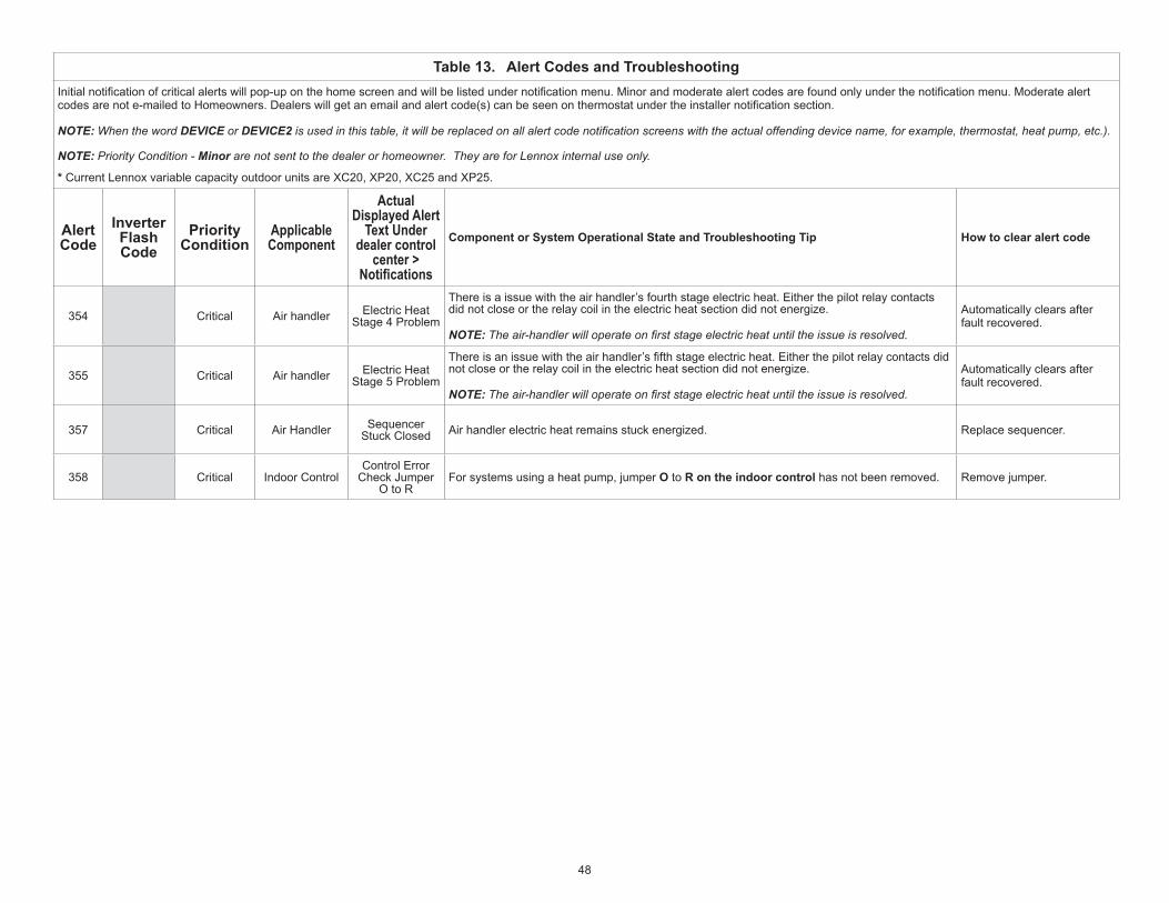
48
Table 13. Alert Codes and TroubleshootingInitialnotificationofcriticalalertswillpop-uponthehomescreenandwillbelistedundernotificationmenu.Minorandmoderatealertcodesarefoundonlyunderthenotificationmenu.Moderatealertcodesarenote-mailedtoHomeowners.Dealerswillgetanemailandalertcode(s)canbeseenonthermostatundertheinstallernotificationsection.
NOTE: When the word DEVICE or DEVICE2 is used in this table, it will be replaced on all alert code notification screens with the actual offending device name, for example, thermostat, heat pump, etc.).
NOTE: Priority Condition - Minor are not sent to the dealer or homeowner. They are for Lennox internal use only.
* Current Lennox variable capacity outdoor units are XC20, XP20, XC25 and XP25.
Alert Code
Inverter Flash Code
Priority Condition
Applicable Component
Actual Displayed Alert
Text Under dealer control
center > Notifications
Component or System Operational State and Troubleshooting Tip How to clear alert code
354 Critical Air handler Electric Heat Stage 4 Problem
Thereisaissuewiththeairhandler’sfourthstageelectricheat.Either the pilot relay contacts did not close or the relay coil in the electric heat section did not energize.
NOTE: The air-handler will operate on first stage electric heat until the issue is resolved.
Automatically clears after fault recovered.
355 Critical Air handler Electric Heat Stage 5 Problem
Thereisanissuewiththeairhandler’sfifthstageelectricheat.Either the pilot relay contacts did not close or the relay coil in the electric heat section did not energize.
NOTE: The air-handler will operate on first stage electric heat until the issue is resolved.
Automatically clears after fault recovered.
357 Critical Air Handler Sequencer Stuck Closed Air handler electric heat remains stuck energized. Replace sequencer.
358 Critical Indoor ControlControl Error
Check Jumper O to R
Forsystemsusingaheatpump,jumperO to R on the indoor control has not been removed. Removejumper.

49
Table 13. Alert Codes and TroubleshootingInitialnotificationofcriticalalertswillpop-uponthehomescreenandwillbelistedundernotificationmenu.Minorandmoderatealertcodesarefoundonlyunderthenotificationmenu.Moderatealertcodesarenote-mailedtoHomeowners.Dealerswillgetanemailandalertcode(s)canbeseenonthermostatundertheinstallernotificationsection.
NOTE: When the word DEVICE or DEVICE2 is used in this table, it will be replaced on all alert code notification screens with the actual offending device name, for example, thermostat, heat pump, etc.).
NOTE: Priority Condition - Minor are not sent to the dealer or homeowner. They are for Lennox internal use only.
* Current Lennox variable capacity outdoor units are XC20, XP20, XC25 and XP25.
Alert Code
Inverter Flash Code
Priority Condition
Applicable Component
Actual Displayed Alert
Text Under dealer control
center > Notifications
Component or System Operational State and Troubleshooting Tip How to clear alert code
370 Critical FurnaceInterlock Switch
Open(Float Switch)
CommunicatingMode:
NOTE: The on-board jumper DS-R (W914) will be cut.
In communicating mode, the DS-R terminal is used with the EL296 and SL280 furnaces and will beusedtomonitorafield-installedinterlockswitchsuchasforexampleafloatswitch.
When operating in this capacity, the DSjumperwillbemonitoredasfollows:• When no alert codes are present there will be 24VAC present at this terminal. • When control see the loss of 24VAC for two minutes it will send an alert code 370 and disable
heating function.• If currently running a demand it will de-energize all outputs (including the blower). • In case of an existing interlock switch alert code, upon power reset, an alert code message will
be sent if voltage is not sensed on the DS terminal. • An alert code clearing message will be sent if 24VAC is sensed on DS terminal for the minimum
of 10 seconds. • The monitoring of DS terminal will apply to both variable speed and constant torque controls.
Non-CommunicatingMode:
NOTE: The on-board jumper DS-R (W914) will NOT be cut.
The furnace control has not received 24VAC power for two minutes or more on the DS termi-nal
• The system will not operate.• Dealer has cut the W914jumper(Dehum,HarmonyIII)ontheLennoxfurnacecontrol.• The thermostat monitors the DS terminal in the furnace for power and if the link has been cut
then power will be lost to DS.• If DS to RterminalisaccidentallycutyoumustreconnectajumperfromtheDS to R on the
terminals strip.
This alert code will clear when 24VAC is continuously sensed on DS terminal for a minimum of 10 seconds or on a power reset.
371 Moderate / Critical Air handler Float Switch
Sensed Open After being active for 10 minutes (600 seconds) the priority condition will change to Critical. Automatically clears after fault recovered.
380 Moderate / Critical
Equipment interface module
Interlock Relay Failure
Interlock relay failure (furnace or air handler modes only).
• Interlock relay is energized, but input is not sensed after three seconds. • Therewillbenoheatingorcoolingduetothisalertcode–moderatecondition.• De-energizeinterlockrelayandenergizeafterfiveminutesifdemandisstillpresent–critical
condition.
Automatically clears after fault recovered.
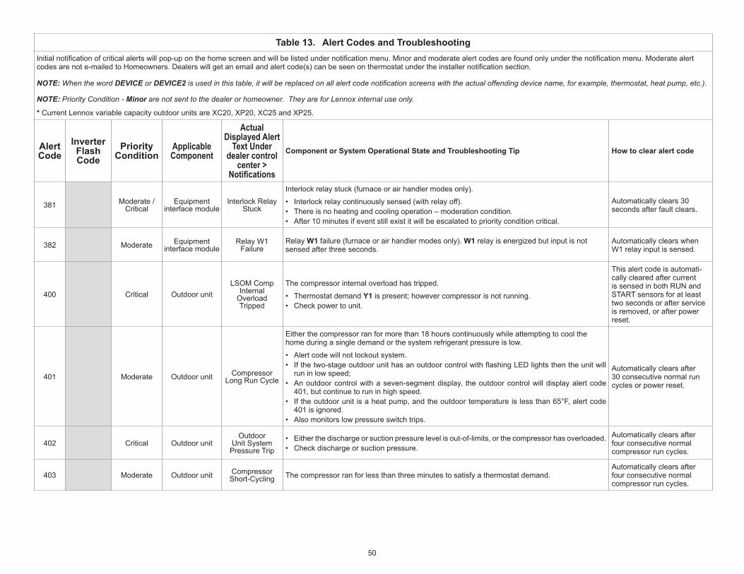
50
Table 13. Alert Codes and TroubleshootingInitialnotificationofcriticalalertswillpop-uponthehomescreenandwillbelistedundernotificationmenu.Minorandmoderatealertcodesarefoundonlyunderthenotificationmenu.Moderatealertcodesarenote-mailedtoHomeowners.Dealerswillgetanemailandalertcode(s)canbeseenonthermostatundertheinstallernotificationsection.
NOTE: When the word DEVICE or DEVICE2 is used in this table, it will be replaced on all alert code notification screens with the actual offending device name, for example, thermostat, heat pump, etc.).
NOTE: Priority Condition - Minor are not sent to the dealer or homeowner. They are for Lennox internal use only.
* Current Lennox variable capacity outdoor units are XC20, XP20, XC25 and XP25.
Alert Code
Inverter Flash Code
Priority Condition
Applicable Component
Actual Displayed Alert
Text Under dealer control
center > Notifications
Component or System Operational State and Troubleshooting Tip How to clear alert code
381 Moderate / Critical
Equipment interface module
Interlock Relay Stuck
Interlock relay stuck (furnace or air handler modes only).
• Interlock relay continuously sensed (with relay off). • Thereisnoheatingandcoolingoperation–moderationcondition.• After 10 minutes if event still exist it will be escalated to priority condition critical.
Automatically clears 30 seconds after fault clears.
382 Moderate Equipment interface module
Relay W1 Failure
Relay W1 failure (furnace or air handler modes only). W1 relay is energized but input is not sensed after three seconds.
Automatically clears when W1 relay input is sensed.
400 Critical Outdoor unitLSOM Comp
Internal Overload Tripped
The compressor internal overload has tripped.
• Thermostat demand Y1 is present; however compressor is not running. • Check power to unit.
This alert code is automati-cally cleared after current is sensed in both RUN and START sensors for at least two seconds or after service is removed, or after power reset.
401 Moderate Outdoor unit Compressor Long Run Cycle
Either the compressor ran for more than 18 hours continuously while attempting to cool the home during a single demand or the system refrigerant pressure is low.
• Alert code will not lockout system.• Ifthetwo-stageoutdoorunithasanoutdoorcontrolwithflashingLEDlightsthentheunitwill
run in low speed;• An outdoor control with a seven-segment display, the outdoor control will display alert code
401, but continue to run in high speed.• If the outdoor unit is a heat pump, and the outdoor temperature is less than 65°F, alert code
401 is ignored. • Also monitors low pressure switch trips.
Automatically clears after 30 consecutive normal run cycles or power reset.
402 Critical Outdoor unitOutdoor
Unit System Pressure Trip
• Either the discharge or suction pressure level is out-of-limits, or the compressor has overloaded.• Check discharge or suction pressure.
Automatically clears after four consecutive normal compressor run cycles.
403 Moderate Outdoor unit Compressor Short-Cycling The compressor ran for less than three minutes to satisfy a thermostat demand.
Automatically clears after four consecutive normal compressor run cycles.

51
Table 13. Alert Codes and TroubleshootingInitialnotificationofcriticalalertswillpop-uponthehomescreenandwillbelistedundernotificationmenu.Minorandmoderatealertcodesarefoundonlyunderthenotificationmenu.Moderatealertcodesarenote-mailedtoHomeowners.Dealerswillgetanemailandalertcode(s)canbeseenonthermostatundertheinstallernotificationsection.
NOTE: When the word DEVICE or DEVICE2 is used in this table, it will be replaced on all alert code notification screens with the actual offending device name, for example, thermostat, heat pump, etc.).
NOTE: Priority Condition - Minor are not sent to the dealer or homeowner. They are for Lennox internal use only.
* Current Lennox variable capacity outdoor units are XC20, XP20, XC25 and XP25.
Alert Code
Inverter Flash Code
Priority Condition
Applicable Component
Actual Displayed Alert
Text Under dealer control
center > Notifications
Component or System Operational State and Troubleshooting Tip How to clear alert code
404 Critical Outdoor unit Compressor Rotor Locked
The compressor rotor is locked up due to either:
• Run capacitor short.• Bearings are seized.• Excessive liquid refrigerant.
NOTE: May need to install hard start kit.
Automatically clears after four consecutive normal run cycles or after power reset.
405 Critical Outdoor Unit Compressor Open Circuit
The compressor circuit is open due to:
• Power disconnection - • Open fuse
Automatically clears after one normal compressor run cycle.
406 Critical Outdoor unitCompressor Open Start
CircuitThe required amount of current is not passing through the START current transformer.
Automatically clears after current is sensed in START sensor, or after power reset.
407 Critical Outdoor unitCompressor Open Run
CircuitThe required amount of current is not passing through RUN current transformer.
Automatically clears after current is sensed in RUN sensor, one normal compres-sor run cycle, or after power reset
408 Critical Outdoor unitCompressor Contactor Welded
The compressor is running continuously.Automatically clears one normal compressor run cycle or after power reset.
409 Moderate Outdoor unit Compressor Voltage Low
The secondary voltage for the applicable system component has fallen below 18VAC. This may be due to:
• Secondary voltage is below 18VAC. • If this continues for 10 minutes, the thermostat will turn off the applicable system component.
Automatically clears after voltage is detected as higher than 20VAC for two seconds or after power reset.
410 Moderate Outdoor unit Open Low Pressure Switch
Unit low pressure is below the required limit.
• Check operating pressures.• Lowpressureswitchopensataspecificpressure(systemshutsdown)andclosesataspecific
pressure (system restarts).
Automatically clears when the system detects that the issue no longer exists.

52
Table 13. Alert Codes and TroubleshootingInitialnotificationofcriticalalertswillpop-uponthehomescreenandwillbelistedundernotificationmenu.Minorandmoderatealertcodesarefoundonlyunderthenotificationmenu.Moderatealertcodesarenote-mailedtoHomeowners.Dealerswillgetanemailandalertcode(s)canbeseenonthermostatundertheinstallernotificationsection.
NOTE: When the word DEVICE or DEVICE2 is used in this table, it will be replaced on all alert code notification screens with the actual offending device name, for example, thermostat, heat pump, etc.).
NOTE: Priority Condition - Minor are not sent to the dealer or homeowner. They are for Lennox internal use only.
* Current Lennox variable capacity outdoor units are XC20, XP20, XC25 and XP25.
Alert Code
Inverter Flash Code
Priority Condition
Applicable Component
Actual Displayed Alert
Text Under dealer control
center > Notifications
Component or System Operational State and Troubleshooting Tip How to clear alert code
411 Critical Outdoor unitLow Pressure Switch Strikes
Lockout
Thelowpressureswitchhasopenedfivetimesduringonecoolingorheatingdemand.
• Thermostat will shut down the outdoor unit.• Openlowpressureswitcherrorcountreachedfivestrikes.• Check system charge using both approach and sub-cooling methods. • Reset by putting outdoor unit control in test mode or resetting low voltage power.
Automatically clears when the system detects that the issue no longer exists.
412 Moderate Outdoor unit Open High Pressure Switch
The unit high pressure is above the upper limit.
• System will shut down.• Confirmthatthesystemisproperlychargedwithrefrigerant.• Check condenser fan motor, expansion valve (if installed), indoor unit blower motor, stuck reversingvalveorcloggedrefrigerantfilter.
• Confirmthattheoutdoorunitisclean.
Automatically clears after the high pressure switch closes or a power reset
413 Critical Outdoor unitHi Pressure
Switch Strikes Lockout
Thehighpressureswitchhasopenedfivetimesduringonecoolingdemand.
• Thermostat will shut down the outdoor unit.• Openhighpressureswitcherrorcountreachedfivestrikes.• Check system charge using superheat and sub-cooling temperatures. • Check outdoor fan operation. • Checkfordirtordebrisblockingairflowtooutdoorunit.• Reset by putting outdoor unit control in test mode or resetting low voltage power.
Automatically clears when the system detects that the issue no longer exists.
414 Moderate Outdoor unitHigh
Discharge Line Temperature
The discharge line temperature is higher than the recommended upper limit of 279ºF.
• Discharge line temperature is greater than 279ºF. • Makesurecoiliscleanandairflowunobstructedinandoutofcondenser.• Check system operating pressures and compare to unit charging charts in installation manual.
Automatically clears after discharge temperature is less than 225ºF.
415 Critical Outdoor unitHi Discharge
Line Temp Strikes Lockout
The discharge line temperature has been consistently higher than the recommended upper limit of 279ºF.
• Dischargelinehightemperatureerrorcountreachedfivestrikesduringasingledemand.• Makesurecoiliscleanandairflowunobstructedinandoutofcondenser.• Check system charge using superheat and sub cooling temperatures. • Reset by putting outdoor control in test mode or resetting low voltage power.
Correct issue and cycle power to the system.
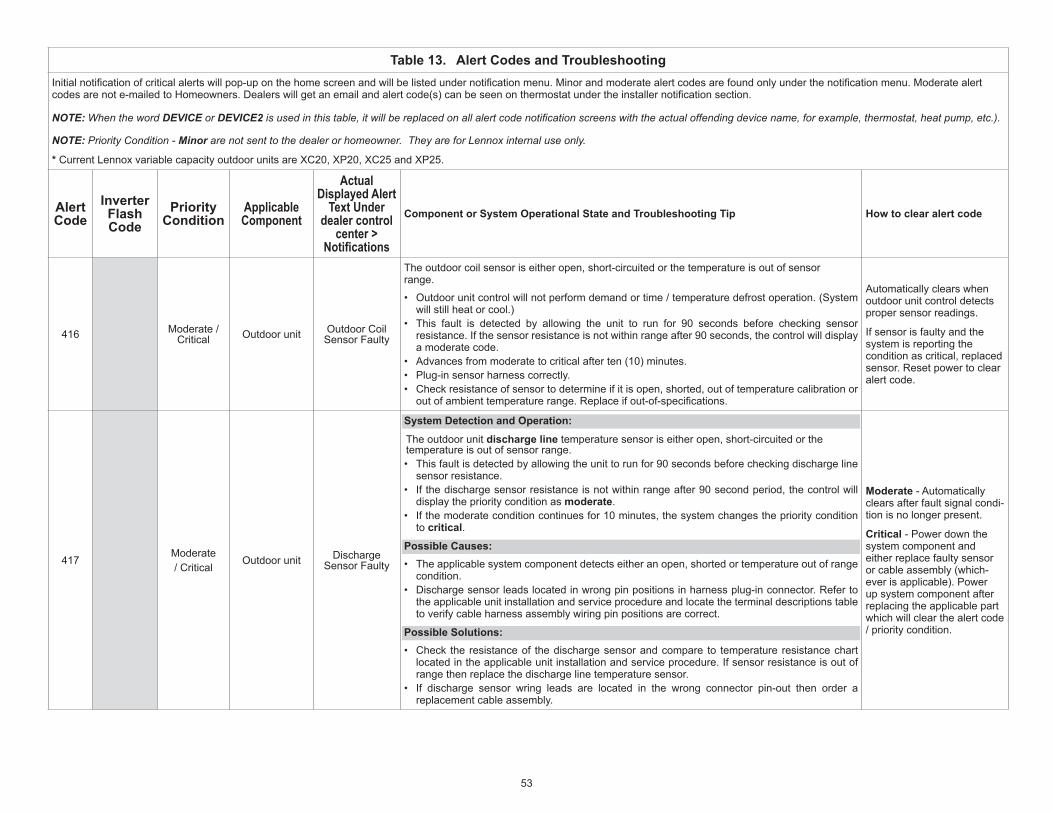
53
Table 13. Alert Codes and TroubleshootingInitialnotificationofcriticalalertswillpop-uponthehomescreenandwillbelistedundernotificationmenu.Minorandmoderatealertcodesarefoundonlyunderthenotificationmenu.Moderatealertcodesarenote-mailedtoHomeowners.Dealerswillgetanemailandalertcode(s)canbeseenonthermostatundertheinstallernotificationsection.
NOTE: When the word DEVICE or DEVICE2 is used in this table, it will be replaced on all alert code notification screens with the actual offending device name, for example, thermostat, heat pump, etc.).
NOTE: Priority Condition - Minor are not sent to the dealer or homeowner. They are for Lennox internal use only.
* Current Lennox variable capacity outdoor units are XC20, XP20, XC25 and XP25.
Alert Code
Inverter Flash Code
Priority Condition
Applicable Component
Actual Displayed Alert
Text Under dealer control
center > Notifications
Component or System Operational State and Troubleshooting Tip How to clear alert code
416 Moderate / Critical Outdoor unit Outdoor Coil
Sensor Faulty
The outdoor coil sensor is either open, short-circuited or the temperature is out of sensor range.
• Outdoor unit control will not perform demand or time / temperature defrost operation. (System will still heat or cool.)
• This fault is detected by allowing the unit to run for 90 seconds before checking sensor resistance. If the sensor resistance is not within range after 90 seconds, the control will display a moderate code.
• Advances from moderate to critical after ten (10) minutes.• Plug-in sensor harness correctly. • Check resistance of sensor to determine if it is open, shorted, out of temperature calibration or outofambienttemperaturerange.Replaceifout-of-specifications.
Automatically clears when outdoor unit control detects proper sensor readings.
If sensor is faulty and the system is reporting the condition as critical, replaced sensor. Reset power to clear alert code.
417Moderate/ Critical
Outdoor unit Discharge Sensor Faulty
SystemDetectionandOperation:
The outdoor unit discharge line temperature sensor is either open, short-circuited or the temperature is out of sensor range. • This fault is detected by allowing the unit to run for 90 seconds before checking discharge line
sensor resistance. • If the discharge sensor resistance is not within range after 90 second period, the control will
display the priority condition as moderate.• If the moderate condition continues for 10 minutes, the system changes the priority condition
to critical.
PossibleCauses:• The applicable system component detects either an open, shorted or temperature out of range
condition.• Discharge sensor leads located in wrong pin positions in harness plug-in connector. Refer to
the applicable unit installation and service procedure and locate the terminal descriptions table to verify cable harness assembly wiring pin positions are correct.
PossibleSolutions:• Check the resistance of the discharge sensor and compare to temperature resistance chart
located in the applicable unit installation and service procedure. If sensor resistance is out of range then replace the discharge line temperature sensor.
• If discharge sensor wring leads are located in the wrong connector pin-out then order a replacement cable assembly.
Moderate - Automatically clears after fault signal condi-tion is no longer present.
Critical - Power down the system component and either replace faulty sensor or cable assembly (which-ever is applicable). Power up system component after replacing the applicable part which will clear the alert code / priority condition.

54
Table 13. Alert Codes and TroubleshootingInitialnotificationofcriticalalertswillpop-uponthehomescreenandwillbelistedundernotificationmenu.Minorandmoderatealertcodesarefoundonlyunderthenotificationmenu.Moderatealertcodesarenote-mailedtoHomeowners.Dealerswillgetanemailandalertcode(s)canbeseenonthermostatundertheinstallernotificationsection.
NOTE: When the word DEVICE or DEVICE2 is used in this table, it will be replaced on all alert code notification screens with the actual offending device name, for example, thermostat, heat pump, etc.).
NOTE: Priority Condition - Minor are not sent to the dealer or homeowner. They are for Lennox internal use only.
* Current Lennox variable capacity outdoor units are XC20, XP20, XC25 and XP25.
Alert Code
Inverter Flash Code
Priority Condition
Applicable Component
Actual Displayed Alert
Text Under dealer control
center > Notifications
Component or System Operational State and Troubleshooting Tip How to clear alert code
418 ModerateEquipment
interface module and outdoor unit
W Output Hardware Fault
There is a faulty W output circuit.
• W terminal is energized while in cooling mode. • Possible cause may be a stuck closed relay on the control, or something external to the control
that is energizing W terminal when it should not be energized. • Disconnect any wiring from the W terminal. • If 24VAC is still present on the terminal, then it is a stuck relay. • If 24VAC disappears, then there is a need to check any of the wires hooked up to the W
terminal.
Automatically clears after fault signal is removed.
419 CriticalEquipment
interface module and outdoor unit
W Output hardware Fault
Lockout
The Woutputhasreportedmorethanfiveerrors.
• The system will shut down the outdoor unit. • The Woutput(alertcode418)ontheoutdoorunithasreportedmorethanfivestrikes.• Disconnect thermostat wire from W and verify there is no 24VAC on the W. • If 24VAC is present, replace the outdoor control.
Automatically clears after power recycled.
420 CriticalAir handler
or equipment interface module
Defrost Out of Control
The heat pump defrost cycle has taken more than 20 minutes to complete.
• Defrost cycle lasts longer than 20 minutes. • Check heat pump operation. • This is applicable only in communicating indoor unit with non-communicating heat pump.
Automatically clears when W1 signal is removed.
421 CriticalEquipment
interface module and outdoor unit
W External Miswire Fault
The W output terminal on the outdoor unit is not wired correctly. Voltage sensed on W output terminal when Y1 out is deactivated.
Automatically clears once voltage is not sensed on output or power is cycled.
422 Moderate Outdoor unitCompressor
Top Cap Switch Open
Compressor top cap switch exceeding thermal limit.
• Check condenser fan motor, TXV and indoor unit blower motor.• Checkforstuckreversingvalveorcloggedrefrigerantfilter.• XC/XP25: Check to ensure that one of the wires from the top cap switch has not been
disconnected from one of the TP terminals on the outdoor control. Reconnect wire if disconnected.
• Check superheat and sub-cooling.
Automatically clears when error is corrected.

55
Table 13. Alert Codes and TroubleshootingInitialnotificationofcriticalalertswillpop-uponthehomescreenandwillbelistedundernotificationmenu.Minorandmoderatealertcodesarefoundonlyunderthenotificationmenu.Moderatealertcodesarenote-mailedtoHomeowners.Dealerswillgetanemailandalertcode(s)canbeseenonthermostatundertheinstallernotificationsection.
NOTE: When the word DEVICE or DEVICE2 is used in this table, it will be replaced on all alert code notification screens with the actual offending device name, for example, thermostat, heat pump, etc.).
NOTE: Priority Condition - Minor are not sent to the dealer or homeowner. They are for Lennox internal use only.
* Current Lennox variable capacity outdoor units are XC20, XP20, XC25 and XP25.
Alert Code
Inverter Flash Code
Priority Condition
Applicable Component
Actual Displayed Alert
Text Under dealer control
center > Notifications
Component or System Operational State and Troubleshooting Tip How to clear alert code
423 40 Moderate / Critical
Variable capacity outdoor
unit*OD Inverter CT Circuit Problem
The inverter has detected a circuit issue.
• When this condition is detected the outdoor control will stop outdoor unit operations and start theanti-shortcycletimer–moderatecondition.
• Outdoorcontrolwilllockoutunitafter10strikeswithinanhour–criticalcondition.• InverterLEDswillflashcode40• Refer to the unit service documentation for troubleshooting procedures.
Inverterflashcode40:
The sequence is:
Red LED: Four Flashes
Green LED: Off
NOTE: Inverter normal operations with no error code present is as follows. Red LED is ON and Green LED is OFF.
A moderate alert code will clear automatically when the inverter detects the condition no longer exist and will send a clear alert code message.
To clear critical alert code disconnect power to outdoor unit and restart.
424 Moderate Outdoor unit OD Liquid Line Sensor Faulty
The liquid line temperature sensor has malfunctioned.
• In normal operation after outdoor control recognizes sensors, the alert code will be sent if a valid temperature reading is lost.
• Compare liquid line sensor resistance to temperature / resistance charts in unit installation instructions.
• Replace sensor pack if necessary. • Atthebeginningof(any)configuration,furnaceorairhandlercontrolwilldetectthepresence
of the sensor(s). • Ifdetected(reading inrange),appropriate featurewillbesetas ‘installed’andshown in thethermostat‘About’screen.
Automatically clears upon configuration,orsensingnormal values.
425 MinorVariable
capacity outdoor unit*
Compressor Speed
Limited by OD Temperature
Outdoor control has in creased minimum com pressor speed to allow for proper oil return due to low ambient temperature.
NOTE: Minimum speed adjustments begin at 45°F and increase to 100% minimum at 17°F.
Outdoor ambient tempera-ture is below system limit. Control attempts to run at lowest allowed compressor speed to allow for proper oil return. Automatically clears when outdoor ambient temperature rises above limit for more than 5 minutes.

56
Table 13. Alert Codes and TroubleshootingInitialnotificationofcriticalalertswillpop-uponthehomescreenandwillbelistedundernotificationmenu.Minorandmoderatealertcodesarefoundonlyunderthenotificationmenu.Moderatealertcodesarenote-mailedtoHomeowners.Dealerswillgetanemailandalertcode(s)canbeseenonthermostatundertheinstallernotificationsection.
NOTE: When the word DEVICE or DEVICE2 is used in this table, it will be replaced on all alert code notification screens with the actual offending device name, for example, thermostat, heat pump, etc.).
NOTE: Priority Condition - Minor are not sent to the dealer or homeowner. They are for Lennox internal use only.
* Current Lennox variable capacity outdoor units are XC20, XP20, XC25 and XP25.
Alert Code
Inverter Flash Code
Priority Condition
Applicable Component
Actual Displayed Alert
Text Under dealer control
center > Notifications
Component or System Operational State and Troubleshooting Tip How to clear alert code
426 CriticalVariable
capacity outdoor unit*
Excessive Inverter Alarms
After10faultswithin60consecutiveminutes,thecontrolwilllockout.Inverterwillflashcodes12to 14 and 53.
NOTE: These inverter codes do not count towards this lockout condition.
To clear disconnect power to outdoor control and restart
427 21 Moderate / Critical
Variable capacity outdoor
unit*OD Inverter DC
Peak Fault
The inverter has detected a DC peak fault condition.
• Ifcondition(55Aorhigher)isdetected,outdoorunitwillstop(compressorandfan)–moderatecondition.
• Anti-short cycle is initiated.• Ifpeakcurrent (55Aorhigher)occurs10 timeswithinanhour,systemwill lockout–critical
condition.• InverterLEDswillflashcode21.• If the unit is a XP20 or XP25 variable capacity heat pump, this error may occur entering or
exiting a defrost cycle as the compressor restarts after the 30 second compressor shift delay. If the unit was manufactured prior to serial number 5817F and has frequent alert code 427, then compare the inverter part number to the latest part number listed in the unit repair parts. Units produced after serial number 5817F which is listed on the unit name plate have an inverter with updated software that includes compressor current slope logic to reduce the potential of alert code 427 instances from occurring during defrost. Replace the inverter with the latest inverter if necessary.
• Refer to the unit service documentation for detailed troubleshooting procedures.
NOTE: Serial number format on unit name plate is PPYYMNNNNN (PP = Manufacturing Plant, YY and M represents the year and month made.
Inverterflashcode21.
The sequence is:
• Red LED: Two Flashes• Green LED: One Flash
NOTE: Inverter normal operations with no error code present is as follows. Red LED is ON and Green LED is OFF.
To clear, disconnect and reconnect power to outdoor control.

57
Table 13. Alert Codes and TroubleshootingInitialnotificationofcriticalalertswillpop-uponthehomescreenandwillbelistedundernotificationmenu.Minorandmoderatealertcodesarefoundonlyunderthenotificationmenu.Moderatealertcodesarenote-mailedtoHomeowners.Dealerswillgetanemailandalertcode(s)canbeseenonthermostatundertheinstallernotificationsection.
NOTE: When the word DEVICE or DEVICE2 is used in this table, it will be replaced on all alert code notification screens with the actual offending device name, for example, thermostat, heat pump, etc.).
NOTE: Priority Condition - Minor are not sent to the dealer or homeowner. They are for Lennox internal use only.
* Current Lennox variable capacity outdoor units are XC20, XP20, XC25 and XP25.
Alert Code
Inverter Flash Code
Priority Condition
Applicable Component
Actual Displayed Alert
Text Under dealer control
center > Notifications
Component or System Operational State and Troubleshooting Tip How to clear alert code
428 22 Moderate / Critical
Variable capacity outdoor
unit*
OD Inverter High Main Input
Current
The inverter has detected a high main input current condition.
• Ifconditionisdetected,outdoorunitwillstop(compressorandfan)–moderatecondition.• Anti-short cycle is initiated.• Ifconditionoccurs10timeswithinanhour,systemwilllockout–criticalcondition.• InverterLEDswillflashcode22.• Refer to the unit service documentation for detailed troubleshooting procedures.
Inverterflashcode22.
The sequence is:
• Red LED: Two Flashes• Green LED: Two Flashes
NOTE: Inverter normal operations with no error code present is as follows. Red LED is ON and Green LED is OFF.
To clear, disconnect power to outdoor unit and restart.

58
Table 13. Alert Codes and TroubleshootingInitialnotificationofcriticalalertswillpop-uponthehomescreenandwillbelistedundernotificationmenu.Minorandmoderatealertcodesarefoundonlyunderthenotificationmenu.Moderatealertcodesarenote-mailedtoHomeowners.Dealerswillgetanemailandalertcode(s)canbeseenonthermostatundertheinstallernotificationsection.
NOTE: When the word DEVICE or DEVICE2 is used in this table, it will be replaced on all alert code notification screens with the actual offending device name, for example, thermostat, heat pump, etc.).
NOTE: Priority Condition - Minor are not sent to the dealer or homeowner. They are for Lennox internal use only.
* Current Lennox variable capacity outdoor units are XC20, XP20, XC25 and XP25.
Alert Code
Inverter Flash Code
Priority Condition
Applicable Component
Actual Displayed Alert
Text Under dealer control
center > Notifications
Component or System Operational State and Troubleshooting Tip How to clear alert code
429 23 Moderate / Critical
Variable capacity outdoor
unit*
OD Inverter DC Link Low
Voltage
The inverter has detected a DC link low voltage condition.
• On a call for compressor operation, if DC link power in inverter does not rise above 180 VDC for 2- and 3-ton models, 250 VDC for 4- and 5-ton models within 30 seconds, the control will display a moderate code.
• Ifconditionisdetected,outdoorunitwillstop(compressorandfan)–moderatecondition.• An anti-short cycle timer is initiated. If condition occurs 10 times within a 60 consecutive minutes,systemwilllockoutanddisplayalertcode429–criticalcondition.
• The outdoor control anti-short cycle timer will time out and the unit will recycle the demand. • InverterLEDswillflashcode23.• Refer to the unit service documentation for detailed troubleshooting procedures. Perform test functionandverifyinverterDClinkandlineinputvoltageandcurrent.Alsocheckinputtofilterboard and reactor before replacing inverter board. To perform this test, go to menu > settings > advanced settings > view dealer control center > tests.
Inverterflashcode23.
The sequence is:
• Red LED: Two Flashes• Green LED: Three Flashes
NOTE: Inverter normal operations with no error code present is as follows. Red LED is ON and Green LED is OFF.
TroubleshootingSuggestions:
• Check wire connections (U, V and W) at inverter plug in harness and compressor.• Check the resistance of compressor windings. If not in range, replace compressor.• Check compressor to ground. If ground issue, replace compressor.• Check input power (Single Phase - 208/230VAC +10%.Ifoutofrange,correctmainpower
issue.• Check DC Link voltage and MICOM Sensing voltage. If out of range, replace inverter. if okay,
possible mechanical issue with compressor.Go to outdoor unit service manual for detail troubleshooting procedures and require values for testing DC link voltages and various insulation resistance characteristics.
Automatically clears when the system detects that the issue no longer exists.

59
Table 13. Alert Codes and TroubleshootingInitialnotificationofcriticalalertswillpop-uponthehomescreenandwillbelistedundernotificationmenu.Minorandmoderatealertcodesarefoundonlyunderthenotificationmenu.Moderatealertcodesarenote-mailedtoHomeowners.Dealerswillgetanemailandalertcode(s)canbeseenonthermostatundertheinstallernotificationsection.
NOTE: When the word DEVICE or DEVICE2 is used in this table, it will be replaced on all alert code notification screens with the actual offending device name, for example, thermostat, heat pump, etc.).
NOTE: Priority Condition - Minor are not sent to the dealer or homeowner. They are for Lennox internal use only.
* Current Lennox variable capacity outdoor units are XC20, XP20, XC25 and XP25.
Alert Code
Inverter Flash Code
Priority Condition
Applicable Component
Actual Displayed Alert
Text Under dealer control
center > Notifications
Component or System Operational State and Troubleshooting Tip How to clear alert code
430 26 Moderate / Critical
Variable capacity outdoor
unit*
OD Inverter Compressor Startup Fail
Compressor start-up failure.
• Ifconditionisdetected,outdoorunitwillstop(compressorandfan)–moderatecondition.• Anti-short cycle is initiated. • Ifconditionoccurs10 timeswithin60consecutiveminutes, thesystemwill lockout–critical
condition.• InverterLEDswillflashcode26.• Refer to the unit service documentation for detailed troubleshooting procedures.
Inverterflashcode26.
The sequence is:
• Red LED: Two Flashes• Green LED: Six Flashes
NOTE: Inverter normal operations with no error code present is as follows. Red LED is ON and Green LED is OFF.
• Check refrigerant• Replace outdoor control board• Replace inverter.
To clear, disconnect power to outdoor unit and restart.
431 27 Moderate / Critical
Variable capacity outdoor
unit*OD Inverter PFC
Fault
The inverter has detected a PFC circuit over-current condition.
• Error occurs when PFC detects an over current condition of 100A peak. • Ifconditionisdetected,outdoorunitwillstop(compressorandfan)–moderatecondition.• Anti-short cycle timer is initiated. • Ifconditionoccurs10 timeswithin60consecutiveminutes, thesystemwill lockout–critical
condition.• InverterLEDswillflashcode27.• Refer to the unit service documentation for detailed troubleshooting procedures.
Inverterflashcode27.
The sequence is:
• Red LED: Two Flashes• Green LED: Seven Flashes
NOTE: Inverter normal operations with no error code present is as follows. Red LED is ON and Green LED is OFF.
To clear, disconnect power to outdoor unit and restart.

60
Table 13. Alert Codes and TroubleshootingInitialnotificationofcriticalalertswillpop-uponthehomescreenandwillbelistedundernotificationmenu.Minorandmoderatealertcodesarefoundonlyunderthenotificationmenu.Moderatealertcodesarenote-mailedtoHomeowners.Dealerswillgetanemailandalertcode(s)canbeseenonthermostatundertheinstallernotificationsection.
NOTE: When the word DEVICE or DEVICE2 is used in this table, it will be replaced on all alert code notification screens with the actual offending device name, for example, thermostat, heat pump, etc.).
NOTE: Priority Condition - Minor are not sent to the dealer or homeowner. They are for Lennox internal use only.
* Current Lennox variable capacity outdoor units are XC20, XP20, XC25 and XP25.
Alert Code
Inverter Flash Code
Priority Condition
Applicable Component
Actual Displayed Alert
Text Under dealer control
center > Notifications
Component or System Operational State and Troubleshooting Tip How to clear alert code
432 28 Moderate / Critical
Variable capacity outdoor
unit*
OD Inverter DC Link High
Voltage
The inverter has detected a DC link high voltage condition.
• Error occurs when the DC link capacitor voltage is greater than 480 VDC. • Ifconditionisdetected,outdoorunitwillstop(compressorandfan)–moderatecondition.• Anti-short cycle timer is initiated. • Ifconditionoccurs10 timeswithin60consecutiveminutes, thesystemwill lockout–critical
condition.• InverterLEDswillflashcode28.• Refer to the unit service documentation for detailed troubleshooting procedures.
Inverterflashcode28.,
The sequence is:
• Red LED: Two Flashes• Green LED: Eight Flashes
NOTE: Inverter normal operations with no error code present is as follows. Red LED is ON and Green LED is OFF.
TroubleshootingSuggestions:
• Check wire connections (U, V and W) at inverter plug in harness and compressor.• Check the resistance of compressor windings. If not in range, replace compressor.• Check compressor to ground. If ground issue, replace compressor.• Check input power (Single Phase - 208/230VAC +10%.Ifoutofrange,correctmainpower
issue.• Check DC Link voltage and MICOM Sensing voltage. If out of range, replace inverter. if okay,
possible mechanical issue with compressor.Go to outdoor unit service manual for detail troubleshooting procedures and require values for testing DC link voltages and various insulation resistance characteristics.
To clear, disconnect power to outdoor unit and restart.

61
Table 13. Alert Codes and TroubleshootingInitialnotificationofcriticalalertswillpop-uponthehomescreenandwillbelistedundernotificationmenu.Minorandmoderatealertcodesarefoundonlyunderthenotificationmenu.Moderatealertcodesarenote-mailedtoHomeowners.Dealerswillgetanemailandalertcode(s)canbeseenonthermostatundertheinstallernotificationsection.
NOTE: When the word DEVICE or DEVICE2 is used in this table, it will be replaced on all alert code notification screens with the actual offending device name, for example, thermostat, heat pump, etc.).
NOTE: Priority Condition - Minor are not sent to the dealer or homeowner. They are for Lennox internal use only.
* Current Lennox variable capacity outdoor units are XC20, XP20, XC25 and XP25.
Alert Code
Inverter Flash Code
Priority Condition
Applicable Component
Actual Displayed Alert
Text Under dealer control
center > Notifications
Component or System Operational State and Troubleshooting Tip How to clear alert code
433 29 Minor / Critical
Variable capacity outdoor
unit*
OD Inverter Compressor Over-current
Compressor phase current is too high.
• During initial startup, a six minute time delay is implement to prevent the alarm from occurring.• Error occurs when compressor peak phase current is greater than 28 amps. • Inverterwillissueinvertercode14firstandslowdowntotrytoreducethecurrent.• Ifthecurrentremainshigh,outdoorunitwillstop(compressorandfan)–moderatecondition.• Cycle timer is initiated.• Ifconditionoccursfivetimeswithin60consecutiveminutes,thesystemwilllockout–critical
condition.• This alert code may be triggered by the inverter or the Lennox variable capacity outdoor
(inverter controlled) unit.• Lennox outdoor control may trigger an this alert code if the inverter reduces the compressor speedwhichisidentifiedasaalertcode441andthecompressorspeed(inhz)isbelowtheminimum speed. This will typically occur at start-up. The inverter automatically increases the compressor minimum speed below 45ºF in the heating mode and above 115ºF ensure the compressorcapacityissufficientforoilreturn.Ifalertcode433occursandinverterdoesnotindicate an inverter code 29, the Lennox communicating Lennox outdoor control triggered the alert code 433.
> Check the Lennox outdoor control software version by accessing the outdoor unit diagnostics section of the icomfort thermostat. The Lennox outdoor control with software versions 1.27 and later have updated software that includes a six minute time delay during the cooling mode and a 11 minute delay during the heating mode after receiving an alert code 433, which typically occurs during start-up.
> If the system is connected to the Internet, the Lennox outdoor control can be updated over the Internet. Make sure the software “auto update” is enabled. The software “auto update” can be toggled to prompt the Lennox server to update the thermostat which will update the Lennox outdoor control. If the system is not connected to the Internet, replace the Lennox outdoor control with catalog number 17D27 or newer version.
• InverterLEDswillflashcode29.• Refer to the unit service documentation for detailed troubleshooting procedures.
Inverterflashcode29.
The sequence is:
• Red LED: Two Flashes• Green LED: Nine Flashes
NOTE: Inverter normal operations with no error code present is as follows. Red LED is ON and Green LED is OFF.
To clear alert code discon-nect power to both the indoor and outdoor units and then reconnect power. Restart system.

62
Table 13. Alert Codes and TroubleshootingInitialnotificationofcriticalalertswillpop-uponthehomescreenandwillbelistedundernotificationmenu.Minorandmoderatealertcodesarefoundonlyunderthenotificationmenu.Moderatealertcodesarenote-mailedtoHomeowners.Dealerswillgetanemailandalertcode(s)canbeseenonthermostatundertheinstallernotificationsection.
NOTE: When the word DEVICE or DEVICE2 is used in this table, it will be replaced on all alert code notification screens with the actual offending device name, for example, thermostat, heat pump, etc.).
NOTE: Priority Condition - Minor are not sent to the dealer or homeowner. They are for Lennox internal use only.
* Current Lennox variable capacity outdoor units are XC20, XP20, XC25 and XP25.
Alert Code
Inverter Flash Code
Priority Condition
Applicable Component
Actual Displayed Alert
Text Under dealer control
center > Notifications
Component or System Operational State and Troubleshooting Tip How to clear alert code
434 53 Moderate / Critical
Variable capacity outdoor
unit*
OD Inverter Comm Error to Main Control
• Outdoor control has lost communications with the inverter continuously during a single thermostat call and one hour period.
• Outdoorcontrolwillstopallcompressordemands–moderatecondition.• Indoor blower will stop functioning.
NOTE: Indoor blower will not run in test mode either when alert code 434 is active. Only after system reset will it operate.
• This alert code will occur if the outdoor unit power is turned off and the indoor unit power (24VAC to Lennox outdoor control) remains on, or if the indoor unit power is turned off (24VAC to Lennox outdoor control) and the outdoor unit power is on. This could occur while performing service or maintenance procedures on the indoor or outdoor unit.
• The Lennox outdoor control will attempt to re-establish communication to the inverter when the alert code 434 occurs by cycling the outdoor unit contactor off for two minutes. Upon energizing the contactor the Lennox outdoor control will attempt to communicate to the inverter for three minutes. This process will be repeated three times in attempt to establish communication before locking out.
• If the unit is locked out with a critical alert code 434, reset the system by cycling the outdoor unit power off and back on. Then cycle the indoor power off (24VAC to the Lennox outdoor control) and then back on.
• If this condition continuously occurs during a one hour period and during a single thermostat call,theoutdoorunitwilllockoutanddisplayalertcode434–criticalcondition.
TroubleshootingOptions:• Check for loose or disconnected electrical connections. • Interruption of main power to inverter. • InverterLEDswillflashcode53.• Refer to the unit service documentation for detailed troubleshooting procedures.
Inverterflashcode53.
The sequence is:
• Red LED: Five Flashes• Green LED: Three Flashes
NOTE: Inverter normal operations with no error code present is as follows. Red LED is ON and Green LED is OFF
Automatically clears when the system detects that the issue no longer exists.
If the unit is locked out with a critical alert code 434, reset thesystembyfirstcyclingthe outdoor unit power off and back. Then cycle the indoor power off (24VAC to the Lennox outdoor control) and then back on.

63
Table 13. Alert Codes and TroubleshootingInitialnotificationofcriticalalertswillpop-uponthehomescreenandwillbelistedundernotificationmenu.Minorandmoderatealertcodesarefoundonlyunderthenotificationmenu.Moderatealertcodesarenote-mailedtoHomeowners.Dealerswillgetanemailandalertcode(s)canbeseenonthermostatundertheinstallernotificationsection.
NOTE: When the word DEVICE or DEVICE2 is used in this table, it will be replaced on all alert code notification screens with the actual offending device name, for example, thermostat, heat pump, etc.).
NOTE: Priority Condition - Minor are not sent to the dealer or homeowner. They are for Lennox internal use only.
* Current Lennox variable capacity outdoor units are XC20, XP20, XC25 and XP25.
Alert Code
Inverter Flash Code
Priority Condition
Applicable Component
Actual Displayed Alert
Text Under dealer control
center > Notifications
Component or System Operational State and Troubleshooting Tip How to clear alert code
435 60 Moderate / Critical
Variable capacity outdoor
unit*
OD Inverter EEPROM
Checksum fault
Inverter internal error.
• When this error occurs, the outdoor control will cycle power to the inverter by opening the contactorfortwominutes–moderatecondition.
• Outdoor control will cycle power to the inverter three times and then outdoor unit is locked out –criticalcondition.
• InverterLEDswillflashcode60.• Refer to the unit service documentation for detailed troubleshooting procedures.
Inverterflashcode60.
The sequence is:
• Red LED: Six Flashes• Green LED: Off
NOTE: Inverter normal operations with no error code present is as follows. Red LED is ON and Green LED is OFF.
To clear alert code discon-nect power to outdoor unit and restart.
436 62 Moderate / Critical
Variable capacity outdoor
unit*
OD Inverter High Heat-Sink Temperature
Inverter heat sink temperature exceeded limit.
• This occurs when the heat sink temperature exceeds the inverter limit. Inverter will issue inverteralertcode13firstandslowdowntotrytocooltheheatsink.
• If temperature remains high, outdoor unit will stop both compressor and fan – moderatecondition.
• Anti- short cycle is initiated. • Ifconditionoccursfivetimeswithinanhour,systemwilllockout–criticalcondition.• The screws that hold the inverter to the inverter board were loose causing poor contact between
these two components.• Tighten screws that hold the heat sink to the inverter control board.
NOTE: Wait five minutes for all capacitors to discharge before checking screws.• InverterLEDswillflashcode62.• Refer to the unit service documentation for detailed troubleshooting procedures.
Inverterflashcode62.
The sequence is:
• Red LED: Six Flashes• Green LED: Two Flashes
NOTE: Inverter normal operations with no error code present is as follows. Red LED is ON and Green LED is OFF.
Moderate condition will automatically clear when the inverter sends an alert code clear message.
Critical condition is cleared by disconnecting power to the outdoor unit and restart.

64
Table 13. Alert Codes and TroubleshootingInitialnotificationofcriticalalertswillpop-uponthehomescreenandwillbelistedundernotificationmenu.Minorandmoderatealertcodesarefoundonlyunderthenotificationmenu.Moderatealertcodesarenote-mailedtoHomeowners.Dealerswillgetanemailandalertcode(s)canbeseenonthermostatundertheinstallernotificationsection.
NOTE: When the word DEVICE or DEVICE2 is used in this table, it will be replaced on all alert code notification screens with the actual offending device name, for example, thermostat, heat pump, etc.).
NOTE: Priority Condition - Minor are not sent to the dealer or homeowner. They are for Lennox internal use only.
* Current Lennox variable capacity outdoor units are XC20, XP20, XC25 and XP25.
Alert Code
Inverter Flash Code
Priority Condition
Applicable Component
Actual Displayed Alert
Text Under dealer control
center > Notifications
Component or System Operational State and Troubleshooting Tip How to clear alert code
437 65 Moderate / Critical
Variable capacity outdoor
unit*
OD Inverter Heat-Sink temp
Sensor Fault
Heat sink temperature sensor fault has occurred (temperature less than 4ºF or greater than 264ºF after 10 minutes of operation).
• When the temperature sensor detects a temperature less than 4ºF or greater than 264ºF after 10 minutes of operation.
• Outdoorunitwillstopbothcompressorandfan–moderatecondition.• Anti-short cycle is initiated. • Ifconditionoccursfivetimeswithinanhour,systemwilllockout–criticalcondition.• InverterLEDswillflashcode65.• Refer to the unit service documentation for detailed troubleshooting procedures.
Inverterflashcode65.
The sequence is:
• Red LED: Six Flashes• Green LED: Five Flashes
NOTE: Inverter normal operations with no error code present is as follows. Red LED is ON and Green LED is OFF.
Moderate priority condition will automatically clear when the inverter sends an alert code clear message.
Critical priority condition can be cleared by disconnecting and reconnecting power to outdoor unit to restart.
438 73 Moderate / Critical
Variable capacity outdoor
unit*
OD Inverter PFC Input Over-
current
The inverter has detected a power factor correction (PFC) circuit over-current condition.• The inverter has detected an PFC over current condition. This may be caused by a high load
condition, high pressure, or outdoor fan failure. • Outdoor controlwill display the codewhen the inverter has detected the error –moderate
condition.• After three minutes, the inverter will reset and the compressor will resume operation. • If the error condition occurs 10 times within a 60 minute rolling time period, the outdoor unit controlwilllockoutoperationoftheoutdoorunit–criticalcondition.
• Possible issue is system running at high pressures. • Check for high pressure trips or other alert codes in thermostat and outdoor control.• InverterLEDswillflashcode73.• Refer to the unit service documentation for detailed troubleshooting procedures.
Inverterflashcode73.
The sequence is:
• Red LED: Seven Flashes• Green LED: Three Flashes
NOTE: Inverter normal operations with no error code present is as follows. Red LED is ON and Green LED is OFF.
Moderate priority condition is automatically cleared when the inverter sends a clear message.
Critical priority condition will automatically clear when inverter is power cycled.

65
Table 13. Alert Codes and TroubleshootingInitialnotificationofcriticalalertswillpop-uponthehomescreenandwillbelistedundernotificationmenu.Minorandmoderatealertcodesarefoundonlyunderthenotificationmenu.Moderatealertcodesarenote-mailedtoHomeowners.Dealerswillgetanemailandalertcode(s)canbeseenonthermostatundertheinstallernotificationsection.
NOTE: When the word DEVICE or DEVICE2 is used in this table, it will be replaced on all alert code notification screens with the actual offending device name, for example, thermostat, heat pump, etc.).
NOTE: Priority Condition - Minor are not sent to the dealer or homeowner. They are for Lennox internal use only.
* Current Lennox variable capacity outdoor units are XC20, XP20, XC25 and XP25.
Alert Code
Inverter Flash Code
Priority Condition
Applicable Component
Actual Displayed Alert
Text Under dealer control
center > Notifications
Component or System Operational State and Troubleshooting Tip How to clear alert code
439 12 ModerateVariable
capacity outdoor unit*
OD Inverter Compressor Slowdown
- High Input Current
Compressor slowdown due to high input current.
• Input current is approaching a high limit. • Compressor speed will automatically slow down. The outdoor control will continue sending the
inverter speed demanded by the thermostat. • The outdoor control will set indoor CFM and outdoor RPM to values according to demand
percentage rather than the actual Hz.• InverterLEDswillflashcode12.• Refer to the unit service documentation for detailed troubleshooting procedures.
Inverterflashcode12.
The sequence is:
• Red LED: One Flash• Green LED: Two Flashes
NOTE: Inverter normal operations with no error code present is as follows. Red LED is ON and Green LED is OFF.
Automatically clears when the condition no longer exists.

66
Table 13. Alert Codes and TroubleshootingInitialnotificationofcriticalalertswillpop-uponthehomescreenandwillbelistedundernotificationmenu.Minorandmoderatealertcodesarefoundonlyunderthenotificationmenu.Moderatealertcodesarenote-mailedtoHomeowners.Dealerswillgetanemailandalertcode(s)canbeseenonthermostatundertheinstallernotificationsection.
NOTE: When the word DEVICE or DEVICE2 is used in this table, it will be replaced on all alert code notification screens with the actual offending device name, for example, thermostat, heat pump, etc.).
NOTE: Priority Condition - Minor are not sent to the dealer or homeowner. They are for Lennox internal use only.
* Current Lennox variable capacity outdoor units are XC20, XP20, XC25 and XP25.
Alert Code
Inverter Flash Code
Priority Condition
Applicable Component
Actual Displayed Alert
Text Under dealer control
center > Notifications
Component or System Operational State and Troubleshooting Tip How to clear alert code
440 13 MinorVariable
capacity outdoor unit*
OD Inverter Compressor Slowdown -
High Heat-Sink temperature
Compressor slowdown due to high heat sink temperature.
• Heat sink temperature is approaching limit. • The compressor speed automatically slows to reduce heat sink temperature. • The control sets indoor CFM and outdoor RPM to values according to demand percentage
rather than the actual Hz. • The screws that hold the inverter to the inverter board may be loose causing poor contact
between these two components.• Tighten screws that hold the heat sink to the inverter control board.
NOTE: Wait five minutes for all capacitors to discharge before checking screws.
• This error code is primarily for informational purposes as the inverter controls the compressor speed to operate within design parameters. Typically the inverter will make a minor speed reductionof4Hz(approximatelya5-6%speedreduction)forabriefperiodoftimeandtoreduce the heat sink temperature and will then resume normal operation. This may occur athighoutdoortemperatures(above110ºF)forbriefperiodsoftime(3–4minutes)andisnormal and expected operation of the inverter controlling the compressor safely within design parameters.
• The inverter finned aluminumheat sink is located on the back side of the inverter in thecondenser air stream. If the alert code 440 occur frequently, especially at lower outdoor temperatures, check the heat sink for debris that may reduce heat transfer or possible obstructionsthatmayimpactairflowacrosstheheatsink.
• Theinverterwillbegintobrieflyreducethecompressorspeedwhentheheatsinktemperaturerises above 185ºF and will allow the inverter to resume the requested compressor demand speed once the inverter heat sink reaches 176ºF. The heat sink temperature, compressor speedinHertz&theInverterCompressorSpeedReductionstatus(“On”or“Off”)notificationcan be viewed under the outdoor unit Diagnostics section of the thermostat dealer control center.
• InverterLEDswillflashcode13.• Refer to the unit service documentation for detailed troubleshooting procedures.
Inverterflashcode13.
The sequence is:
• Red LED: One Flash• Green LED: Three Flashes
NOTE: Inverter normal operations with no error code present is as follows. Red LED is ON and green LED is OFF.
Automatically clears when the condition no longer exists.

67
Table 13. Alert Codes and TroubleshootingInitialnotificationofcriticalalertswillpop-uponthehomescreenandwillbelistedundernotificationmenu.Minorandmoderatealertcodesarefoundonlyunderthenotificationmenu.Moderatealertcodesarenote-mailedtoHomeowners.Dealerswillgetanemailandalertcode(s)canbeseenonthermostatundertheinstallernotificationsection.
NOTE: When the word DEVICE or DEVICE2 is used in this table, it will be replaced on all alert code notification screens with the actual offending device name, for example, thermostat, heat pump, etc.).
NOTE: Priority Condition - Minor are not sent to the dealer or homeowner. They are for Lennox internal use only.
* Current Lennox variable capacity outdoor units are XC20, XP20, XC25 and XP25.
Alert Code
Inverter Flash Code
Priority Condition
Applicable Component
Actual Displayed Alert
Text Under dealer control
center > Notifications
Component or System Operational State and Troubleshooting Tip How to clear alert code
441 14 MinorVariable
capacity outdoor unit*
OD Inverter Compressor
Slowdown - High Compressor
Current
This alert code is for more information than an issue with the system.
• When the inverter gets close to the current or heat sink temperature limit, it will limit the ramp rate. Instead of changing compressor speed at 1 hz/second, it changes to 5 hz/20 seconds.
• Compressor slowdown due to high compressor current.• Compressor current is approaching limit. • The compressor speed automatically slows. • This error code is primarily for informational purposes as the inverter controls the compressor to
operate within design parameters. Alert code 441 typically occurs at startup as the compressor current increases rapidly during startup.
• The inverter will reduce the compressor speed by 4 Hz and slow the compressor ramp up speed to the requested compressor demand speed (capacity). This is normal and expected operation of the inverter to control the inverter within design parameters. In most cases the alert code441notificationdoesnotrequireanyadditionalserviceordiagnosticprocedures.
• The control sets indoor CFM and outdoor RPM to values according to demand percentage rather than the actual Hz.
• Possible issue is system running at high pressures. • Check for high pressure trips or other alert codes in thermostat and outdoor control.• InverterLEDswillflashcode14.• Refer to the unit service documentation for detailed troubleshooting procedures.
Inverterflashcode14.
The sequence is:
• Red LED: One Flash• Green LED: Four Flashes
NOTE: Inverter normal operations with no error code present is as follows. Red LED is ON and green LED is OFF.
Automatically clears when the condition no longer exists.
442 Critical Outdoor unitCompressor
Top Cap Switch Strike Lockout
Thetopcapswitchhasopenedfivetimeswithinonehour.Asaresult,theoutdoorunitislockedout.
• Thisconditionoccurswhencompressorthermalprotectionsensoropensfivetimeswithinonehour.
• Outdoor unit will stop.
To clear, disconnect power to outdoor unit and restart.

68
Table 13. Alert Codes and TroubleshootingInitialnotificationofcriticalalertswillpop-uponthehomescreenandwillbelistedundernotificationmenu.Minorandmoderatealertcodesarefoundonlyunderthenotificationmenu.Moderatealertcodesarenote-mailedtoHomeowners.Dealerswillgetanemailandalertcode(s)canbeseenonthermostatundertheinstallernotificationsection.
NOTE: When the word DEVICE or DEVICE2 is used in this table, it will be replaced on all alert code notification screens with the actual offending device name, for example, thermostat, heat pump, etc.).
NOTE: Priority Condition - Minor are not sent to the dealer or homeowner. They are for Lennox internal use only.
* Current Lennox variable capacity outdoor units are XC20, XP20, XC25 and XP25.
Alert Code
Inverter Flash Code
Priority Condition
Applicable Component
Actual Displayed Alert
Text Under dealer control
center > Notifications
Component or System Operational State and Troubleshooting Tip How to clear alert code
443 Critical Outdoor unitMUC Unit Code
to Inverter Model Mismatch
The Lennox variable capacity unitary control (outdoor control) has incorrect appliance unit size code selected.• Checkforproperconfiguringunderunitsizecodeusedforoutdoorunit(seeunitconfiguration
guide or in installation instructions). • If replacing inverter, verify inverter model matches unit size. • Remove the thermostat from the system while applying power and reprogramming.
Automatically clears after the correct match is detected following a power reset.
444 Critical Heat PumpReversing Valve Relay Failed to
CloseRelay failure. Verify by call for heat pump heating. Check for 24VAC out from O. Replace Outdoor Unit
Control Board
446
Moderate (escalate to
critical after 5 strikes during
a single thermostat demand)
Heat PumpLow Suction
Pressure Fault (Cooling)
Suction pressure < 40 psig in operation.
Error code initially will be a moderate and will escalate to critical and stop system operation. After 5-strikes during a single thermostat demand. Recommend replacement of low pressure switch.
Recommend replacement of low pressure switch.
500
Minor (Escalated to Critical after alert code persists for 15 minutes)
PureAir S Press Sensor Fault
• Pressure sensor reports a fault for more than 5 minutes, or does not respond for more than 5 minutes.
• Device will not perform any pressure reading calculations until fault is recovered. Remaining filterlifedisplaywillindicate“-“whilefaultexists.
Automatically clears 30 seconds after fault is recovered.
501
Minor (Escalated to Critical after alert code persists for 15 minutes)
PureAir S UV Sensor Fault
• Ultra-violet (UV) sensor reports a fault for more than 5 minutes or UV sensor does not respond for more than 5 minutes.
• Device will not perform any UV lamp life remaining calculations until fault has recovered. Life remaining display shall indicate “-“ while fault exists.
Automatically clears 30 seconds after fault is recovered.
502 Critical PureAir S UV Lamp Off The light is determined to be off when the last three last light intensities measurements are below the set threshold.
Light is determined on after 1 setoffivesamplesareabovethe set threshold.
503 Moderate PureAir S Filterlifeat10% Filterliferemainingdeterminedtobe<=10%,butgreaterthan0%. None
504 Critical PureAir S FilterLifeat0% Filterliferemainingdeterminedtobe0%. None

69
Table 13. Alert Codes and TroubleshootingInitialnotificationofcriticalalertswillpop-uponthehomescreenandwillbelistedundernotificationmenu.Minorandmoderatealertcodesarefoundonlyunderthenotificationmenu.Moderatealertcodesarenote-mailedtoHomeowners.Dealerswillgetanemailandalertcode(s)canbeseenonthermostatundertheinstallernotificationsection.
NOTE: When the word DEVICE or DEVICE2 is used in this table, it will be replaced on all alert code notification screens with the actual offending device name, for example, thermostat, heat pump, etc.).
NOTE: Priority Condition - Minor are not sent to the dealer or homeowner. They are for Lennox internal use only.
* Current Lennox variable capacity outdoor units are XC20, XP20, XC25 and XP25.
Alert Code
Inverter Flash Code
Priority Condition
Applicable Component
Actual Displayed Alert
Text Under dealer control
center > Notifications
Component or System Operational State and Troubleshooting Tip How to clear alert code
505 Moderate PureAir SPureAir Model
Selection Changed
ModelSelectionjumperhaschangedpositions.Jumper repositioned back tooriginaljumperpositionorsystem rebooted.
506 Critical PureAir S UV Lamp Life at0% Ultravioletlamplifeisat0%. None
507 Critical PureAir S Filter Calibration Failure
• Filter calibration determined failed due to all test cfm static pressures reading <= 7 Pa.• Send alert code immediately.• Nofiltertestsorlifecalculationoccurwhilethisalertcodeisactive.
Clear alert code upon initiationofanotherfiltercalibration.
530 Moderate iHarmony Low Damper 24VAC Voltage
• Check 24VAC voltage to all dampers. • Check 24VAC damper transformer. • Check connections.
Replace transformer if applicable.
532 Moderate IHarmonyZoning Pressure Switch Opened (High Pressure)
Zoning Pressure Switch Opened (high pressure).
• Compressorpressureisabovethespecifiedlimit.• Compressor is turned off. • Zoning will be restored once the high pressure switch closes.OccasionallywegetthiswithanACsystemandthefixistojustjumpoutthepressureswitchterminals on the damper control module board.
Automatically clears after compressor pressure is within limits.

70
Table 13. Alert Codes and TroubleshootingInitialnotificationofcriticalalertswillpop-uponthehomescreenandwillbelistedundernotificationmenu.Minorandmoderatealertcodesarefoundonlyunderthenotificationmenu.Moderatealertcodesarenote-mailedtoHomeowners.Dealerswillgetanemailandalertcode(s)canbeseenonthermostatundertheinstallernotificationsection.
NOTE: When the word DEVICE or DEVICE2 is used in this table, it will be replaced on all alert code notification screens with the actual offending device name, for example, thermostat, heat pump, etc.).
NOTE: Priority Condition - Minor are not sent to the dealer or homeowner. They are for Lennox internal use only.
* Current Lennox variable capacity outdoor units are XC20, XP20, XC25 and XP25.
Alert Code
Inverter Flash Code
Priority Condition
Applicable Component
Actual Displayed Alert
Text Under dealer control
center > Notifications
Component or System Operational State and Troubleshooting Tip How to clear alert code
542 Moderate/ Critical
iHarmony Zone Sensor 1
Zone 1 Temp Sensor Problem
Possible Causes:
• Zone temperature sensor reading out of range.• Check for loose or incorrectly wired connections at the zone sensor or damper control module
terminals.• Openorshortzonetemperaturesensordetectedformorethanfivesecond.• More than one zone sensor has the same assigned zone number. Check zone sensor(s) zone
number assignment.System Response:
• Both types of zone sensors will display “--” as the indoor temperature on the main screen. • Damper control module will operate in central mode (all dampers open) in both moderate and
critical priority conditions.• If after 10 minutes the condition does not change, the applicable alert code (542, 543, 544 or
545) is escalate by the Lennox communicating thermostat to critical. System will continue to operate in central mode.
• At the Lennox communicating thermostat, only zone 1 screen will be available.
NOTE: The Lennox communicating thermostat will display the alert code as “Problem (Zoning Control)”. Email notifications will describe the issue as “ Zone “X” Temp Sensor Problem.
Automatically clears 30 seconds after condition no longer exist.
543 Moderate/ Critical
iHarmony Zone Sensor 2
Zone 2 Temp Sensor Problem
544 Moderate/ Critical
iHarmony Zone Sensor 3
Zone 3 Temp Sensor Problem
545 Moderate/ Critical
iHarmony Zone Sensor 4
Zone 4 Temp Sensor Problem
551 Critical Zone Sensor and iHarmony
Lost Communications
Any lost communication between any zone sensor and the damper control module will result in applicable alert code(s) being displayed (543, 544 or 545) at the thermostat.
• A pop-up display on the thermostat will appear indicating a communication error.• Indoortemperatureforthespecificzoneinerrorwilldisplayedas“--”onthehomescreen.• When any zone sensor loses communication with the damper control module, the entire system
will go into central mode (single temperature control).Check for loose, damage or incorrect wiring between damper control module and the zone sensor reporting alert code 551.
Once communication is reestablished the zone sen-sor will return to normal zone operations.
594 Moderate / Critical
Equipment interface module
Pre-Coil Air temp Sensor
Problem
Pre-coil discharge air temperature sensor problem (dual-fuel mode only). This alert code will escalate from moderate to critical after ten (10) minutes. This may result in no heating or cooling operations.
Possible cause for alert code 594 is the interlock relay is energized, but no input is sensed after three seconds.
Thismayberesolvebyde-energizingtheinterlockrelayandre-energizedfiveminuteslaterifdemand is still present.
Alert code automatically clearsfiveminutesafterfaultis cleared.

71
Table 13. Alert Codes and TroubleshootingInitialnotificationofcriticalalertswillpop-uponthehomescreenandwillbelistedundernotificationmenu.Minorandmoderatealertcodesarefoundonlyunderthenotificationmenu.Moderatealertcodesarenote-mailedtoHomeowners.Dealerswillgetanemailandalertcode(s)canbeseenonthermostatundertheinstallernotificationsection.
NOTE: When the word DEVICE or DEVICE2 is used in this table, it will be replaced on all alert code notification screens with the actual offending device name, for example, thermostat, heat pump, etc.).
NOTE: Priority Condition - Minor are not sent to the dealer or homeowner. They are for Lennox internal use only.
* Current Lennox variable capacity outdoor units are XC20, XP20, XC25 and XP25.
Alert Code
Inverter Flash Code
Priority Condition
Applicable Component
Actual Displayed Alert
Text Under dealer control
center > Notifications
Component or System Operational State and Troubleshooting Tip How to clear alert code
600 Minor Outdoor unit Load Shed Event
Compressor has been cycled OFF on utility load shedding.
• Load shedding function provides a method for a local utility company to limit the maximum power level usage of the outdoor unit.
• The feature is activated by applying 24VAC power across the L and C terminals on the outdoor control
Automatically clears when L terminal is inactive.
601 Minor Heat PumpOD Unit Low
Ambient Operational
Lockout
• Outdoor unit has been cycled off on low temperature protection. • Outdoor unit will not operate when the outdoor ambient is at or below 4°F (-15.6°C).• If the unit is satisfying a demand (running) and the outdoor ambient drops below 4°F (-15.6°C), theunitwillcontinuetooperateuntil thedemandhasbeensatisfiedor theoutdoorambientdrops to 15°F (-9.4°C) which will result in the unit being locked out (shut down).
Automatically clears when low temperature condition no longer exists.
610 CriticalHD display
(Thermostat)
Low Room Temperature
Detected
Thisalertwillautomaticallynotifiedtheuserthatalowroomtemperatureconditionexist.Anotifi-cationisdisplayedontheHDdisplayandemailnotificationsenttohomeowneranddealer.
The freeze alert protection parameter range is 30°F to 50°F (-1.11 to 10.0°C). Default is 40°F (4.44°C).
NOTE: Notification is dependent on the thermostat having a active Wi-Fi connection and the user account has been setup and includes a valid email address.
Automatically clears when condition is resolved.
611 CriticalHD display
(Thermostat)
High Room Temperature
Detected
Thisalertwillautomaticallynotifiedtheuserthatahighroomtemperatureconditionexist.Anoti-ficationisdisplayedontheHDdisplayandemailnotificationsenttohomeowneranddealer.
The heat alert protection parameter range is 80°F to 100°F (26.67 to 37.78°C). Default is 90°F (32.22°C).
NOTE: Notification is dependent on the thermostat having a active Wi-Fi connection and the user account has been setup and includes a valid email address.
Automatically clears when condition is resolved.
700 CriticalHD display
(Thermostat)
Comfort Sensor Temp Sensor
Problem
TheHDdisplay’sinternaltemperaturesensorisnotoperatingcorrectly.Toresolvethisissue,trythe following:
• Remove HD display from mag-mount and reattaching.• Seal hole in wall behind mag-mount to minimize exposure to unconditioned air from inside the
wall.• Run “reset all” under dealer control center. • If issue persist, then replace the HD display.
Automatically clears when the system detects that the issue no longer exists.

72
Table 13. Alert Codes and TroubleshootingInitialnotificationofcriticalalertswillpop-uponthehomescreenandwillbelistedundernotificationmenu.Minorandmoderatealertcodesarefoundonlyunderthenotificationmenu.Moderatealertcodesarenote-mailedtoHomeowners.Dealerswillgetanemailandalertcode(s)canbeseenonthermostatundertheinstallernotificationsection.
NOTE: When the word DEVICE or DEVICE2 is used in this table, it will be replaced on all alert code notification screens with the actual offending device name, for example, thermostat, heat pump, etc.).
NOTE: Priority Condition - Minor are not sent to the dealer or homeowner. They are for Lennox internal use only.
* Current Lennox variable capacity outdoor units are XC20, XP20, XC25 and XP25.
Alert Code
Inverter Flash Code
Priority Condition
Applicable Component
Actual Displayed Alert
Text Under dealer control
center > Notifications
Component or System Operational State and Troubleshooting Tip How to clear alert code
701 ModerateHD display
(Thermostat)TSTAT Temp Above Limit
The thermostat is reading indoor temperatures above the pre-programmed limit. The thermostat hasabuilt-innon-adjustablehighlimitof99°F.
• Cool thermostat.• Adjustsetpoint.• Run reset all under dealer control center. • Replace HD display or mag-mount, if needed.
Automatically clears when the system detects that the issue no longer exists.
900 ModerateHD display
(Thermostat)Temperature
Control ProblemSomething is causing the system not to be able to reach set point. Check for dirty coil, low refrigerant or verify the system is not under size for the application.
Automatically clears when the system detects that the issue no longer exists.
901Moderate(On/Off) Default
HD display(Thermostat)
Smart Alert Modes: Heating
& Cooling (Smart)
This feature is disabled by default. Go to dealer control center and enable feature under Smart Hub.
This alert occurs when temperature consistently diverges away from set-point in the following two conditions:
• When system is running high stage/full speed.• When the system is not providing demand when there is a call for one. Typically when system
locked out.Thecoolingcapacityalertdoesn’tworkinzoning.
If alert code exist must be manually cleared.
65537 Critical mag-mount Missing Base• Base not detected and alarm 65538 has been raised over 30 times.• Amber LED is displayed on smart hub.• Mount and wire mag-mount before powering up smart hub.
Automatically clears once is detected for two seconds.
65538 Minor mag-mount Missing Base• Base not detected for at least 30 seconds.• Amber LED is displayed on smart hub.• Mount and wire mag-mount before powering up smart hub.
Automatically clears once is detected for two seconds.

73
Table 13. Alert Codes and TroubleshootingInitialnotificationofcriticalalertswillpop-uponthehomescreenandwillbelistedundernotificationmenu.Minorandmoderatealertcodesarefoundonlyunderthenotificationmenu.Moderatealertcodesarenote-mailedtoHomeowners.Dealerswillgetanemailandalertcode(s)canbeseenonthermostatundertheinstallernotificationsection.
NOTE: When the word DEVICE or DEVICE2 is used in this table, it will be replaced on all alert code notification screens with the actual offending device name, for example, thermostat, heat pump, etc.).
NOTE: Priority Condition - Minor are not sent to the dealer or homeowner. They are for Lennox internal use only.
* Current Lennox variable capacity outdoor units are XC20, XP20, XC25 and XP25.
Alert Code
Inverter Flash Code
Priority Condition
Applicable Component
Actual Displayed Alert
Text Under dealer control
center > Notifications
Component or System Operational State and Troubleshooting Tip How to clear alert code
65539 CriticalHD display
(Thermostat)Missing TSTAT
• HD wall display not detected for more than 30 seconds.• Solid blue LED will appear on mag-mount if powered. Only on versions with mag-mount.• Flashing blue LED will appear if not communicating with smart hub. Only on versions with
mag-mount.• Typically the thermostat will send a command to the unknown device and place it in a soft
disable state.The Lennox communicating control with the soft disable state will indicate so as follows:
• On air handler, furnace and outdoor controls, the state is displayed by double horizontal lines on seven-segment display.
• Onthedampercontrolmodule,thegreenLEDwillflash3secondsonand1secondoff.• Ontheequipmentinterfacemodule,thegreenLEDwillflash3secondsonand1secondoff.Cycling power to the soft disabled control may clear the condition. If cycling power does not clear the soft disable state then replace control.
Automatically clears once is detected for two seconds.
65540 MinorHD display
(Thermostat)Missing HD wall
display
• HD wall display not detected for less than 30 seconds.• Solid blue LED will appear on mag-mount if powered. Only on versions with mag-mount.• Blinking blue LED will appear if not communicating with smart hub. Only on versions with mag-
mount.• Typically the thermostat will send a command to the unknown device and place it in a soft
disable state.The Lennox communicating control with the soft disable state will indicate so as follows:
• On air handler, furnace and outdoor controls, the state is displayed by double horizontal lines on seven-segment display.
• On the damper control module, the green LED will blink three seconds on and one second off.• On the equipment interface module, the green LED will blink three seconds on and one second
off.Cycling power to the soft disabled control may clear the condition. If cycling power does not clear the soft disable state then replace control.
Automatically clears once is detected for two seconds.

74
Table 13. Alert Codes and TroubleshootingInitialnotificationofcriticalalertswillpop-uponthehomescreenandwillbelistedundernotificationmenu.Minorandmoderatealertcodesarefoundonlyunderthenotificationmenu.Moderatealertcodesarenote-mailedtoHomeowners.Dealerswillgetanemailandalertcode(s)canbeseenonthermostatundertheinstallernotificationsection.
NOTE: When the word DEVICE or DEVICE2 is used in this table, it will be replaced on all alert code notification screens with the actual offending device name, for example, thermostat, heat pump, etc.).
NOTE: Priority Condition - Minor are not sent to the dealer or homeowner. They are for Lennox internal use only.
* Current Lennox variable capacity outdoor units are XC20, XP20, XC25 and XP25.
Alert Code
Inverter Flash Code
Priority Condition
Applicable Component
Actual Displayed Alert
Text Under dealer control
center > Notifications
Component or System Operational State and Troubleshooting Tip How to clear alert code
65541 Minor HD display Download-failed
• Downloadforfirmwarefailed.• Typically the thermostat will send a command to the unknown device and place it in a soft
disable state.The Lennox communicating control with the soft disable state will indicate so as follows:
• On air handler, furnace and outdoor controls, the state is displayed by double horizontal lines on seven-segment display.
• On the damper control module, the green LED will blink three seconds on and one second off.• On the equipment interface module, the green LED will blink three seconds on and one second
off.Cycling power to the soft disabled control may clear the condition. If cycling power does not clear the soft disable state then replace control.
Not applicable.
65542 Minor Thermostat Hashverificationfailed
• Hasverificationfailed.Updatefailed.• Solid blue LED will appear on mag-mount if powered. Only on versions with mag-mount.• Blinking blue LED will appear if not communicating with smart hub. Only on versions with mag-
mount.• Typically the thermostat will send a command to the unknown device and place it in a soft
disable state.The Lennox communicating control with the soft disable state will indicate so as follows:
• On air handler, furnace and outdoor controls, the state is displayed by double horizontal lines on seven-segment display.
• On the damper control module, the green LED will blink three seconds on and one second off.• On the equipment interface module, the green LED will blink three seconds on and one second
off.Cycling power to the soft disabled control may clear the condition. If cycling power does not clear the soft disable state then replace control.
Not applicable.
Automatically clears once is detected for two seconds.
65543 InfoHD display
(Thermostat)Firmware updated
• Whennewfirmwarehasbeensuccessfullyupdatedtothethermostat.• Typically the thermostat will send a command to the unknown device and place it in a soft
disable state.The Lennox communicating control with the soft disable state will indicate so as follows:• On air handler, furnace and outdoor controls, the state is displayed by double horizontal lines
on seven-segment display.• Onthedampercontrolmodule,thegreenLEDwillflash3secondsonand1secondoff.• Ontheequipmentinterfacemodule,thegreenLEDwillflash3secondsonand1secondoff.Cycling power to the soft disabled control may clear the condition. If cycling power does not clear the soft disable state then replace control.
Clears automatically after successfully update.

75
Table 13. Alert Codes and TroubleshootingInitialnotificationofcriticalalertswillpop-uponthehomescreenandwillbelistedundernotificationmenu.Minorandmoderatealertcodesarefoundonlyunderthenotificationmenu.Moderatealertcodesarenote-mailedtoHomeowners.Dealerswillgetanemailandalertcode(s)canbeseenonthermostatundertheinstallernotificationsection.
NOTE: When the word DEVICE or DEVICE2 is used in this table, it will be replaced on all alert code notification screens with the actual offending device name, for example, thermostat, heat pump, etc.).
NOTE: Priority Condition - Minor are not sent to the dealer or homeowner. They are for Lennox internal use only.
* Current Lennox variable capacity outdoor units are XC20, XP20, XC25 and XP25.
Alert Code
Inverter Flash Code
Priority Condition
Applicable Component
Actual Displayed Alert
Text Under dealer control
center > Notifications
Component or System Operational State and Troubleshooting Tip How to clear alert code
65544 CriticalHD display
(Thermostat)Too many siblings
Thesystemislimitedtonomorethanfive(5)smarthubsassignedtoonegroup.Youcanhaveuptoninegroups(1-9)withfivesmarthubsassignedtoeach.Ifyouhavemorethan5smarthubs assigned to a single group, then alert code 65544 will be displayed.
IfyouDONOTexceedthefivesmarthubspergrouplimitation,youwillNOTgetanalertcode65544.
EXAMPLE: If you had two groups with six smart hubs assigned to each group, then you would get each minute twelve alert code 65544 notifications.
Once the system detects that onlyfiveorlesssmarthubsare detected in one group will the alert code automati-cally clears.
65545Moderate(On/Off) Default
HD display(Thermostat)
Cooling Capacity Alert
Coolingoperationmaynotbesufficientforthehottestdays.Basedonlocalconditionsandclimatological data for zip code.
EXAMPLE: Dirty Filter, Low Refrigerant charge, TXV, etc. Symptom during mild tempera-tures may include; system running longer than normal but not showing any other symptoms.
Auto cleared on next predic-tion

76
4. ServiceNotificationCodes
5. Electrical Troubleshooting
5.1. Overview
The purpose of the service and application note is to address electrical troubleshooting of various connections between Lennox communicating equipment and the applicable expected voltages. Use these voltages to:• Resolve double dashes on in-zone sensors.• Determine whether the wire is bad or the device is faulty.• Determine which wire is bad in the bundle.• Resolve “missing outdoor unit”.• Resolve“can’tfindLennoxcommunicatingindoorunit”.
5.2. Definitions• Naked = control has no wires on it at all• Loaded = voltage from c to i- / i+ when all four wires are on• Landed = voltage from c to i- / i+ without r wired on board• Transformervoltageisspecificandbestwiththreedecimalplaces.Forexample28.316
» Thousandths always bounces and is okay. » Hundredths can bounce but not wide range » Tenths should never bounce
1. Ifitdoesalmosteverytimeitisafloatswitchthatisbreakingr to the thermostat
2. Complaint of system waiting
3. History of active Alert Codes 105 and 120.
4. Codes not related to equipment
5. Blank screens
6. Wi-Fi will not stay connected.

77
5.3. iComfort® S30 (Smart Hub 1.0)
R l+ l- C + - A B12VDC COMM BUS
Figure 1. iComfort® S30 smart hub 1.0
TESTING:• Naked = Control has no wires on it at all• Loaded = Voltage from c to i- / i+ when all four wires are ON• Landed = Voltage from c to i- / i+ without r wired on control.
Most Common Readings (S30 smart hub 1.0 Power and Communication Terminals)Terminals Naked Landedl+toC 3.5VDC(l+naked) 2.5 VDC
l- to C 1.5 VDC (l- naked) 2.5 VDC
Most Common Readings (S30 smart hub 1.0 Mag Mount Power and Communication Terminals)Terminals Voltage Reading12VDC+to- 12.4 VDC
12 VDC - to COMM BUS A 1.74 VDC
12 VDC - to COMM BUS B 1.74 VDC

78
5.4. iComfort® S30 (Smart Hub 2.0 and 3.0)
R l+ l- C ACC1 ACC2 + - A B12VDC COMM BUS
Figure 2. iComfort® S30 Smart Hub 2.0
+ -COMMBUS
A BR i+ I- C ACC1 ACC2
Figure 3. iComfort® S30 Smart Hub 3.0

79
5.5. iComfort® E30 (Smart Hub 1.0 and 2.0)
W1 W2 W3 G Y2 Y1 C DS R H O B
UNIT TYPE
HEATSTAGES
OUTDO
OR
AIR SENSO
R
DISCHARGE
AIR SENSO
R
HP
IFC
AHC
0 1 2 3
COMM A
BUSB
12VDC+ -ACC2ACC1
Figure 4. iComfort® E30 Smart Hub 1.0
W1 W2 W3 G Y2 Y1 C DS R H O B
UNIT TYPE
HEATSTAGES
OUTDO
OR
AIR SENSO
R
DISCHARGE
AIR SENSO
R
HP
IFC
AHC
0 1 2 3
Front(Hinged Cover Removed)
+ -COMMBUS
A BACC1 ACC2
Figure 5. iComfort® E30 Smart Hub 2.0

80
TESTING:• Naked = Control has no wires on it at all• Loaded = Voltage from c to i- / i+ when all four wires are ON• Landed = Voltage from c to i- / i+ without r wired on control.
Most Common Readings (E30 Smart Hub 2.0 and S30 Smart Hub 3.0 Power and Communication Terminals)Terminals Naked Landedl+toC 3.5VDC(l+naked) 2.5 VDC
l- to C 1.5 VDC (l- naked) 2.5 VDC
Most Common Readings (E30 Smart Hub 1.0 and S30 Smart Hub 2.0 Mag Mount Power and Communication Terminals)Terminals Naked Loaded Landed12VDC+to- 11.68 VDC 11.68 VDC 12.0 VDC
12 VDC - to COMM BUS A 1.67 VDC 1.66 VDC 1.64 VDC
12 VDC - to COMM BUS B 1.58 VDC 1.41 VDC 1.57 VDC
5.6. Lennox Communicating Indoor / Outdoor Units and Equipment Interface Module
Various EquipmentC to i+ and i- Terminals Naked Loaded LandedGas Furnace (IFC) 2.84 VDC 2.615 VDC 1.9 VDC
Air Handlers (AHC) 2.44 VDC 2.5 VDC 1.7 VDC
Equipment Interface Module (EIM) 2.44 VDC 2.4 VDC 1.7 VDC
Outdoor Unit with IFC 0 2.615 VDC 1.9 VDC
Outdoor Unit with AHC 0 2.45 VDC 1.7 VDC

81
6. Thermostat Wiring Termination in Communicating Systema. Wiring TerminationsCommunicating systems require four thermostat wires between the thermostat and the furnace/air handler control and four wires between the outdoor unit and the furnace/air handler control. When a thermostat cable with more than four wires is used, the extra wires must be properly connected to avoid electrical noise. The wires must not be left disconnected.Use a wire nut to bundle the four unused wires at each end of the cable. Each bundle should also include an additional wire that should be connected on one end to the Cterminalasshowninthefigurebelow.NOTE: Terminations are not required for non-communicating terminals.
Communicating Indoor UnitS30 version 2 and 3
S30 version 1
Single Wire ToC Terminal
Unused Wires
Unused Wires
Single Wire ToC Terminal
Communicating Outdoor Unit
R l+ l- C + - A B12VDCCOMM BUS
W1 W2 W3 G Y2 Y1 C DS R H O B
UNIT TYPE
HEATSTAGES
OU
TDO
OR
AIR
S
EN
SO
R
DIS
CH
AR
GE
AIR
S
EN
SO
R
HP
IFC
AH
C
0 1 2 3
COMM A
BUSB
12VDC+ -ACC2ACC1
E30 version 1 and 2
Figure 6. Extra Wiring Terminations

82
7. Wiring Type RequirementsUse18AWGun-shieldedthermostatcable(field-provided)fornon-communicationwiring.Wehighlyrecommendusingone-pair22AWGshieldedthermostatcablefor all communications terminals which will help eliminate any noise interference.
Table 14. S30 Ultra Smart Hub (3.0) Terminal Designations, Order and Wiring RequirementsTerminal Designation Description Thermostat Wiring
R 24VAC input18AWG unshielded
C 24VAC returnI+ RS-BUSI+
18 - 22AWG shielded (recommended)I- RS-BUS I-
ACC1 Accessory 1 and 2 (typically can be used for 1 or 2 speed ventilators and fresh air damper)NOTE: Requires Smart Hub Control Software Revision 03.50.
xxx or higher.
18AWG unshieldedACC2
12+ 12VDC output18AWG unshielded
12- 12VDC returnA Communications bus A
18 - 22AWG shielded (recommended)B Communications bus B
Use18AWGun-shieldedthermostatcable(field-provided)forpowerterminals(R,C,12+and12-).Wehighlyrecommendusing18-22AWGshieldedthermostatcableforcommunicationsterminals(I+,I-,AandB)whichwillhelpeliminateanynoiseinterference.
Table 15. E30 Smart Hub (2.0) Terminal Designations, Order and Wiring RequirementsTerminal Designation Description Thermostat Wiring
ACC1 Accessory 1 and 2 (typically can be used for 1 or 2 speed ventilators and fresh air damper). NOTE: Requires Smart Hub Control Software Revision 03.50.
xxx or higher.
18AWG unshieldedACC2
12+ 12VDC output18AWG unshielded
12- 12VDC returnA Communications bus A
18- 22AWG shielded (recommended) B Communications bus B
Table 16. Equipment Interface Module (EIM) Terminal Designations, Order and Wiring RequirementsLabel Function / Description Thermostat Wiring
R 24VAC communication power Input18AWG unshielded
C 24VAC communication common power Inputi+ Communicationhigh–dataline
18 - 22AWG shielded (recommended)i- Communicationlow–dataline

83
Table 17. iHarmony Damper Control Module (DCM) Terminal Designations, Order and Wiring Requirements
Component to Component Terminal Wiring Cable Requirement Wiring Type Maximum Distance between Components
Damper Control Module to Indoor Unit or 17A20 Zone Sensor
R 24VAC input18AWG unshielded
197 feet (50 meters)C 24VAC return
I+ RS-BUSI+18 - 22AWG shielded (recommended)
I- RS-BUS I-
Damper Control Module to 50A93 Freezestat Freezestat
18AWG,unshieldedthermostatcable(field-provided)
197 feet (50 meters)
Damper Control Module to 93G35 Freezestat Freezestat 197 feet (50 meters)
Damper Control Module to 27W13 High Pressure Switch
Pressure Switch
18AWG,unshieldedthermostatcable(field-provided) 197 feet (50 meters)
Damper Control Module to 88K3801 Discharge Air Tem-perature Sensor
DATS18AWG,unshieldedthermostatcable(field-provided). Use if less than 6 feet (2 meters) distance.
30 feet (9 meters) twisted pair wire. Suggest ordering cable 27M19 (yellow).
Damper Control Module to Dampers Dampers 18AWG,unshieldedthermostatcable(field-
provided) Check with damper manufacturer

84
Homeowner System SettingsTable 18. User Settings Menu Navigation
Level 1 Level 2 Level 3 Level 4 Level 5
Wi-FiWi-fi(onoroff)
Wi-finetworkselection
AwaySmart Away (on or off)
Awayset-pointsadjustment
Feels Like Feels like temperature (on or off)
Fan
NOTE: Fan mode Auto, ON, or OFF is set from the home screen under modes/schedules.
Allergen Defender (on or off)
Circulatedurationadjustment
Heat & CoolWider set-point range (on or off)
Safety protection (on or off)
Humidity
Humidity Control
NOTE: Humidification and dehumidification settings are dependent on hardware accessories installed.
Off
HumidityDehumidificationcontrolcenter
Normal
Max
Dew point
Humidificationset-point
Dehumidify
Dehumidificationcontrolcenter
Normal
Max
Climate IQ (Auto)
Overcooling
Dehumidificationset-point
Humidify+Dehumidify
Dehumidificationcontrolcenter
Normal
Max
Dew point
Dehumidificationcontrolcenter
Normal
Max
Climate IQ (Auto)
Overcooling
Dew Point
Humidificationset-point(left)+Dehumidificationset-point(right)
iHarmony zoning
Zoning (on or off)
Zone 1 (master) - Select to rename zone.
Zone 2 - Select to rename zone.
Zone 3 - Select to rename zone.
Zone 4 - Select to rename zone.

85
Table 18. User Settings Menu NavigationLevel 1 Level 2 Level 3 Level 4 Level 5
Notifications
Replacefilter1 Disable
3 months
6 months
12 months
24 months
Custom > Set date
Calender time
run time
Replacefilter2
Replace UV bulb
Replacehumidifierpad
PureAir maintenance
Maintenance Reminder
Advanced Settings
View dealer control center (See table XX for further details.)
Restart
Restart smart hub
Restart Thermostat
Restart Both
Pair smart hub to iComfort Dealer Mobile App
General About
iComfortThermostat Model Number
Thermostat Serial Number
Thermostat
Control Model Number
Control Serial Number
Control Hardware Revision
Control Software Revision
Serial Protocol Version
Software UpdateAutomatic Updates (on or off)
Check for Updates Now
smart hub
Control Model Number
Control Serial Number
Control Hardware Revision
Control Software Revision
MAC Address
Software UpdateAutomatic Updates (on or off)
Check for Updates Now

86
Table 18. User Settings Menu NavigationLevel 1 Level 2 Level 3 Level 4 Level 5
General
Dealer Info
Name
Country/Region United States, Canada or Australia
Address 1
Address 2
City
State Select State
Zip/postal code
Phone
Website
Dealer Info Dealer Access
Remote View (on or off)
Remote Control (on or off)
AlertsandNotifications(onoroff)
Screen Lock
Unlock
Partially Lock
Locked
Date & Time 24 hour time (yes or no)
Language
English
French
Spanish
Display
Outdoor Weather (on or off)
Outdoor Temperature DisplayInternet (AccuWeather)
Sensor
Indoor Humidity (on or off)
PureAir S Life (on or off)
Proximity Sensor (on or off)
Screen Saver
Off
Weather
NOTE: Thermostat must be connect to the Internet.
Power Save
NOTE: Black screen, wakes up on proximity or touch.
Photo
NOTE: Photo must be upload via consumer web portal or iComfort consumer mobile app.
Screen Brightness Auto brightness (on or off)
Temp ScaleFahrenheit ºF
Celsius ºC

87
Table 18. User Settings Menu NavigationLevel 1 Level 2 Level 3 Level 4 Level 5
Display Clean Screen (30 second counter)
Home Info
Home Name
Country/Region United States, Canada or Australia
Address
Address 2
City
State Select State
Zip/postal code
Remove Home
Account
NOTE: Must be connected to Internet.
Password
Forgot Password Please enter your email to retrieve your password
Sign In
Create New Account
New Account
First Name
Last Name
Phone
Login (email)
Set PasswordPassword
Verify Password
Receive Alerts and Reminders via Email (on or off)
Allow dealers to receive service alerts and if possibleremotelyfixtheproblem Check Box
I agree to the Lennox EULA Check Box
Create account
Generate Pin Pin Number is Displayed.
Homekit
Enter WAC mode
Auto WAC Mode (yes or no)
HomeKit Factory Reset

88
8. Change Log• 9/2018 - Initial Release
• 10/2018-Addedminoralertsandservicenotificationcodesandcorrectedverbiageinseveralalertcodedescriptions.AddedLEDindicatordescriptionsforE30andfirstandsecondgenerationS30smarthubs.
• 4/2019 - Includes features like ventilation in Firmware release 3.50.xx. Updates to various parameter and alert code descriptions.
• 5/2019 - Updates to alarm text for alert code 114, 312, 240, 430 and 441.
• 12/2019 - Details added concerning smart hub 3.0.
• 1/2020 - added section 7 concerning the type of wiring to use for communicating terminals.
• 3/2020-Correctederrorreferencingthethermostat’sabilitytoadjustHRV/ERVventilationrates(see“Table1.SmartHubParameters”onpage2).
• 6/2020 - Added alarm codes 181, 182 and 446. Changed error codes 434 to eliminate hard lockout. Change 440, 441 and 443 to Minors.
• 23/2021 -Change text for Alert Code 180.