Embed Size (px)
Citation preview
Lenovo Chassis Management Module 2 User's Guide
Note
Before using this information and the product it supports, read the general information in Appendix B “Notices” on page 101, the Warranty Information document, and the Safety Information and the Environmental Notices and User Guide documents on the Lenovo documentation CD.
Tenth Edition (March 2020)
© Copyright Lenovo 2016, 2020. LIMITED AND RESTRICTED RIGHTS NOTICE: If data or software is delivered pursuant to a General Services Administration (GSA) contract, use, reproduction, or disclosure is subject to restrictions set forth in Contract No. GS-35F-05925.
Contents
Chapter 1. Introduction . . . . . . . . . 1Before you begin . . . . . . . . . . . . . . . 1Accessibility features for the Lenovo Flex System CMM . . . . . . . . . . . . . . . . . . . . 2Notices and statements in this document . . . . . . 2Software requirements for the CMM web interface. . . . . . . . . . . . . . . . . . . 3
Chapter 2. Web interface use and reference . . . . . . . . . . . . . . . . . 5Starting the web interface . . . . . . . . . . . . 5Configuring the CMM using the web interface . . . . 5
Using the Initial Setup Wizard . . . . . . . . 6Setting the CMM power management policies . . . . . . . . . . . . . . . . 16Resetting the CMM to manufacturing defaults . . . . . . . . . . . . . . . . 17External authentication of certificates . . . . 18
Configuring chassis components . . . . . . . . 23Setting the chassis air filter reminder . . . . . 24Configuring a storage node . . . . . . . . 25Updating compute node firmware . . . . . . 26
User authority management . . . . . . . . . . 29Monitoring CMM events . . . . . . . . . . . 33Starting a remote compute node session . . . . . 34Saving a CMM configuration . . . . . . . . . . 35Restoring a CMM configuration. . . . . . . . . 36Booting from the standby CMM . . . . . . . . 39Enabling the CMM floating IP address . . . . . . 39CMM ports . . . . . . . . . . . . . . . . 39
Chapter 3. CMM web interface overview . . . . . . . . . . . . . . . . 43Web interface pages and user roles . . . . . . . 43Web interface options . . . . . . . . . . . . 46
System Status Options . . . . . . . . . . 46Monitoring Multiple Chassis . . . . . . . . 52Event log options . . . . . . . . . . . . 53Service and support options . . . . . . . . 55Chassis management options . . . . . . . 62CMM management options . . . . . . . . 82
Appendix A. Getting help and technical assistance . . . . . . . . . . . . . . . 97Before you call . . . . . . . . . . . . . . . 97Using the documentation . . . . . . . . . . . 98Getting help and information from the World Wide Web . . . . . . . . . . . . . . . . . . . 98How to send service data . . . . . . . . . . . 98Creating a personalized support web page . . . . 98Software service and support . . . . . . . . . 98Hardware service and support . . . . . . . . . 99Taiwan product service . . . . . . . . . . . . 99
Appendix B. Notices. . . . . . . . . . 101Trademarks . . . . . . . . . . . . . . . . 102Important notes . . . . . . . . . . . . . . . 102Recycling information . . . . . . . . . . . . 102Particulate contamination . . . . . . . . . . . 103Telecommunication regulatory statement . . . . . 103Electronic emission notices . . . . . . . . . . 104
Federal Communications Commission (FCC) statement . . . . . . . . . . . . . . . 104Industry Canada Class A emission compliance statement . . . . . . . . . . . . . . . 104Avis de conformité à la réglementation d'Industrie Canada. . . . . . . . . . . . 104Australia and New Zealand Class A statement . . . . . . . . . . . . . . . 104European Union EMC Directive conformance statement . . . . . . . . . . . . . . . 104Germany Class A statement . . . . . . . . 105Japanese electromagnetic compatibility statements . . . . . . . . . . . . . . . 106Korea Communications Commission (KCC) statement . . . . . . . . . . . . . . . 106Russia Electromagnetic Interference (EMI) Class A statement . . . . . . . . . . . . 106People's Republic of China Class A electronic emission statement . . . . . . . . . . . 107Taiwan Class A compliance statement . . . . 107Taiwan BSMI RoHS declaration . . . . . . . 108
Index . . . . . . . . . . . . . . . . . . 109
© Copyright Lenovo 2016, 2020 i

ii Lenovo Chassis Management Module 2User's Guide
Chapter 1. Introduction
Use the Chassis Management Module 2 web interface to perform chassis management functions within a web browser.
The CMM web interface communicates with the management program to execute chassis management tasks. You can use perform the following tasks and more:
• Access I/O modules and configure them.
• Initialize storage nodes
• Change the startup sequence in a compute node
• Configure security settings such as data encryption and user account security
• Control the chassis, compute nodes, and other components.
• Define login IDs and passwords
• Discover other chassis on the network and enable access to them
• Monitor the status of the compute nodes and other components
• Select recipients for alert notification of specific events
• Set the date and time.
• Use a remote console for the compute nodes
Notes:
• Unless otherwise noted, the term “CMM” in this document refers to all CMM types.
• The CMM2 is also called the CMM II.
The Lenovo Chassis Management Module 2 supports multiple Flex System chassis types. The CMM automatically detects the chassis type where it is installed. The CMM firmware adjusts the features it supports and options it displays based on its operating environment.
You can also perform management functions through the CMM SNMP management interface and the command-line interface (CLI). See “Using the Lenovo Chassis Management Module 2 CLI” in the Lenovo Chassis Management Module 2 Command-Line Interface Reference Guide for more information.
Compatible browsers are listed on the initial login screen of the CMM web interface.
The most recent versions of all Lenovo Flex System documentation are available from http:// flexsystem.lenovofiles.com/help/index.jsp.
Note: Do not store any sensitive information in the CMM web server directory or subdirectories. Data in the directories is accessible to unauthenticated users.
Before you beginBefore you use the CMM web interface, you must complete some specific tasks.
Complete the following tasks before you start the CMM web interface:1. The CMM must be installed in a correctly configured Flex System chassis. See "Installing, removing, and
replacing components" in the Lenovo Chassis Management Module 2 Installation Guide for installation instructions.
© Copyright Lenovo 2016, 2020 1
2. A client computer must be connected to the CMM through a correctly configured Ethernet connection. See "Connecting to the CMM" in the Lenovo Flex System Chassis Management Module 2 Installation Guide for detailed instructions.
Accessibility features for the Lenovo Flex System CMMAccessibility features help users who have disabilities, such as restricted mobility or limited vision, to use information technology products successfully.
Accessibility features
Accessibility for the Lenovo Flex SystemCMM interface is provided through the command-line interface. The remote console video feed is not accessible to a screen reader. If you are managing your Lenovo Flex System by using the optional Lenovo XClarity Administrator or Flex System Manager management software, see the documentation for the management device for information about its accessibility features.
The Lenovo Flex System information center is accessibility-enabled. The information center has the following accessibility features:
• Keyboard-only operation.
• Interfaces that are commonly used by screen readers. (The Java access bridge must be installed to make Java applets available to the JAWS screen reader.)
• The attachment of alternative input and output devices.
Keyboard navigation
This product uses standard Microsoft Windows navigation keys.
Related accessibility information
You can view the publications for Lenovo Flex System in Adobe Portable Document Format (PDF) by using the Adobe Acrobat Reader. The PDF files are provided on a CD that is packaged with the product, or you can access them through the Lenovo Flex System information center.
Lenovo and accessibility
See the Accessibility website for more information about the commitment that Lenovo has to accessibility.
Notices and statements in this documentUse this information to understand the most common documentation notices and statements and how they are used.
The caution and danger statements in this document are also in the multilingual Safety Information document, which is on the Lenovo documentation CD. Each statement is numbered for reference to the corresponding statement in the Safety Information document.
The following notices and statements are used in this document:
• Note: These notices provide important tips, guidance, or advice.
• Important: These notices provide information or advice that might help you avoid inconvenient or problem situations.
• Attention: These notices indicate possible damage to programs, devices, or data. An attention notice is placed just before the instruction or situation in which damage might occur.
• Caution: These statements indicate situations that can be potentially hazardous to you. A caution statement is placed just before the description of a potentially hazardous procedure step or situation.
2 Lenovo Chassis Management Module 2User's Guide

• Danger: These statements indicate situations that can be potentially lethal or hazardous to you. A danger statement is placed just before the description of a potentially lethal or hazardous procedure step or situation.
Software requirements for the CMM web interfaceFollowing are the CMM web interface software requirements.
The CMM web interface does not support double-byte character set (DBCS) languages. For information about using the compute node integrated management module (IMM) interface, see the compute node or IMM documentation.
Chapter 1. Introduction 3

4 Lenovo Chassis Management Module 2User's Guide
Chapter 2. Web interface use and reference
Use this information to help you navigate the CMM web interface and manage components in a Flex System chassis. Detailed information about the web interface is in the CMM web interface online help.
Starting the web interfaceStart the CMM web interface to monitor and configure components in the chassis.
You can access the CMM web interface through an Ethernet connection by establishing a session with the URL of the CMM. If you are connecting to the CMM for the first time, you might have to change the Internet protocol properties on the client computer. See "Connecting to the CMM" in the Lenovo Flex System Chassis Management Module 2 Installation Guide for more information.
To log in to the CMM web interface, complete the following steps:1. Point your browser to the CMM web interface URL that your system administrator defined during initial
configuration.
2. Type your CMM user ID and password (assigned by a system administrator). The password is case sensitive. The user ID is not case sensitive. The default CMM user name is USERID, and the default password is PASSW0RD (note the number zero, not the letter O, in PASSW0RD).
3. Click Log In.
Note: The available password options depend on the password options that are configured for the Flex System chassis.
Configuring the CMM using the web interfaceYou can configure the primary CMM from the CMM web interface. If a standby CMM is installed, it automatically receives the configuration and status information from the primary CMM.
The Flex System chassis automatically detects the modules and compute nodes that are installed and stores the vital product data (VPD). When the chassis is started, the CMM automatically configures the remote management and console (Ethernet) connector of the CMM, so that you can configure and manage Lenovo Flex System components. You configure and manage Lenovo Flex System components remotely by using the CMM web interface.
When the Flex System chassis is started for the first time, the CMM automatically configures its remote management port, enabling you to establish a management connection. See "Connecting to the CMM" in the Lenovo Chassis Management Module 2 Installation Guide for information.
Note: Each CMM is configured with the same static IP address. You must create a unique static IPv4 or IPv6 address for each CMM. If DHCP is not used, only one CMM at a time can be added onto the network for discovery. Adding more than one CMM to the network without a unique IP address assignment for each will result in IP address conflicts. If you have problems connecting, see "Resolving CMM connection problems" in the Lenovo Chassis Management Module 2 Installation Guide for help with troubleshooting.
If the CMM that is being installed is a replacement for the only CMM in the chassis and you selected the Backup Configuration to File option before you replaced the CMM, you can apply the saved configuration file to the replacement CMM using the passphrase that you created.
Important: Be sure to save your configuration file passphrase for future use.
© Copyright Lenovo 2016, 2020 5
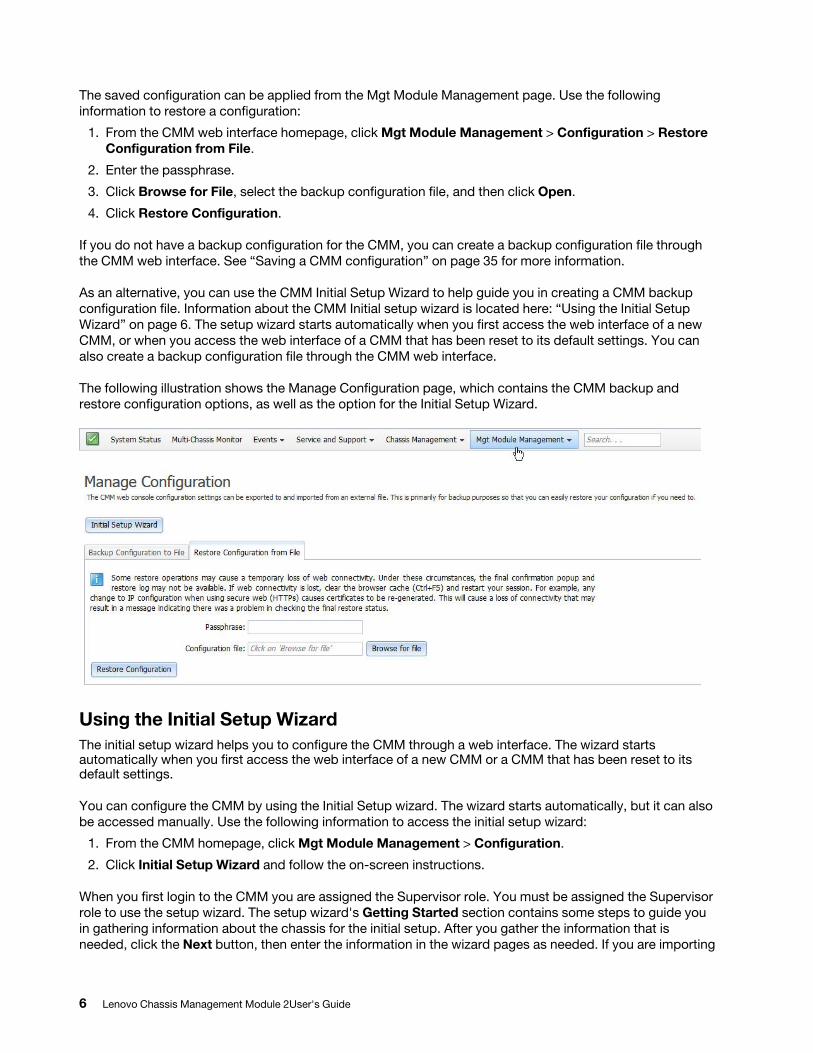
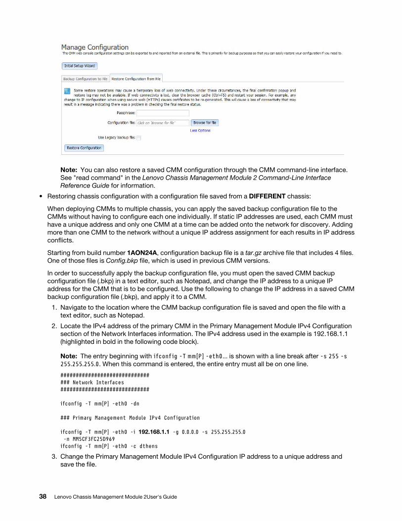
The saved configuration can be applied from the Mgt Module Management page. Use the following information to restore a configuration:
1. From the CMM web interface homepage, click Mgt Module Management > Configuration > Restore Configuration from File.
2. Enter the passphrase.
3. Click Browse for File, select the backup configuration file, and then click Open.
4. Click Restore Configuration.
If you do not have a backup configuration for the CMM, you can create a backup configuration file through the CMM web interface. See “Saving a CMM configuration” on page 35 for more information.
As an alternative, you can use the CMM Initial Setup Wizard to help guide you in creating a CMM backup configuration file. Information about the CMM Initial setup wizard is located here: “Using the Initial Setup Wizard” on page 6. The setup wizard starts automatically when you first access the web interface of a new CMM, or when you access the web interface of a CMM that has been reset to its default settings. You can also create a backup configuration file through the CMM web interface.
The following illustration shows the Manage Configuration page, which contains the CMM backup and restore configuration options, as well as the option for the Initial Setup Wizard.
Using the Initial Setup WizardThe initial setup wizard helps you to configure the CMM through a web interface. The wizard starts automatically when you first access the web interface of a new CMM or a CMM that has been reset to its default settings.
You can configure the CMM by using the Initial Setup wizard. The wizard starts automatically, but it can also be accessed manually. Use the following information to access the initial setup wizard:
1. From the CMM homepage, click Mgt Module Management > Configuration.
2. Click Initial Setup Wizard and follow the on-screen instructions.
When you first login to the CMM you are assigned the Supervisor role. You must be assigned the Supervisor role to use the setup wizard. The setup wizard's Getting Started section contains some steps to guide you in gathering information about the chassis for the initial setup. After you gather the information that is needed, click the Next button, then enter the information in the wizard pages as needed. If you are importing
6 Lenovo Chassis Management Module 2User's Guide
a saved CMM configuration, the option to select the configuration file is in the Import Existing Configuration page of the wizard. Follow the on screen instructions, then click the Next button.
You can view and print the configuration information after the wizard has finished. A basic configuration of the CMM will be completed after the setup wizard has finished.
Notes:
• If you have problems connecting, see "Resolving CMM connection problems" in the Lenovo Chassis Management Module 2 Installation Guide for help with troubleshooting.
• If you are unable to connect to your CMM from all user accounts because you have forgotten the account IDs and passwords, you must restore the CMM to the manufacturing default configuration (see "Restoring the CMM manufacturing default configuration" in the Lenovo Chassis Management Module 2 Installation Guide for information).
• You can configure the CMM by using the optional Lenovo XClarity Administrator (see http:// flexsystem.lenovofiles.com/help/topic/com.lenovo.lxca.doc/aug_product_page.html).
• You can configure the CMM by using the optional Flex System Manager management software (see http:// flexsystem.lenovofiles.com/help/topic/com.lenovo.acc.8731.doc/product_page.htmlFlex System Manager Software Installation and Service Guide).
When the Flex System chassis is started for the first time, the CMM automatically configures its remote management port, enabling you to establish a management connection. See "Configuring the CMM for remote access" in the Lenovo Chassis Management Module 2 Installation Guide for information.
Note: When the CMM is set to Secure security mode, only the secure file transfer methods, HTTPS and SFTP, can be used for firmware updates and other tasks involving file transfers, such as transferring a backup configuration file to restore a configuration. The unsecure file transfer protocols HTTP, FTP, and TFTP are disabled when security is set to the Secure mode.
The following illustrations show the Initial Setup Wizard pages. The system information that is displayed in the wizard pages might be different from your system.
Chapter 2. Web interface use and reference 7
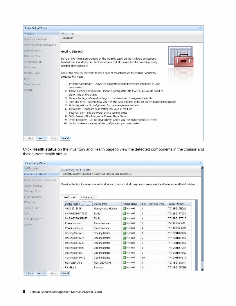
Click Health status on the Inventory and Health page to view the detected components in the chassis and their current health status.
8 Lenovo Chassis Management Module 2User's Guide
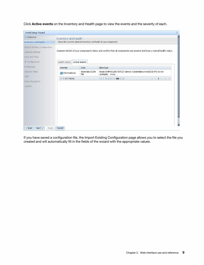
Click Active events on the Inventory and Health page to view the events and the severity of each.
If you have saved a configuration file, the Import Existing Configuration page allows you to select the file you created and will automatically fill in the fields of the wizard with the appropriate values.
Chapter 2. Web interface use and reference 9
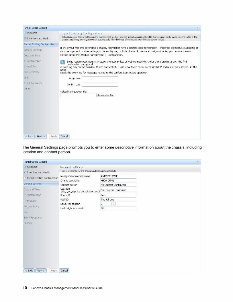
The General Settings page prompts you to enter some descriptive information about the chassis, including location and contact person.
10 Lenovo Chassis Management Module 2User's Guide
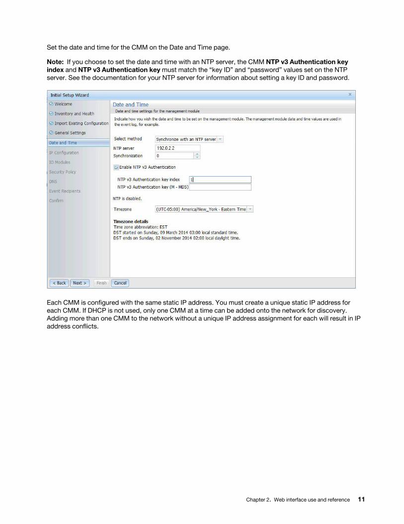
Set the date and time for the CMM on the Date and Time page.
Note: If you choose to set the date and time with an NTP server, the CMM NTP v3 Authentication key index and NTP v3 Authentication key must match the “key ID” and “password” values set on the NTP server. See the documentation for your NTP server for information about setting a key ID and password.
Each CMM is configured with the same static IP address. You must create a unique static IP address for each CMM. If DHCP is not used, only one CMM at a time can be added onto the network for discovery. Adding more than one CMM to the network without a unique IP address assignment for each will result in IP address conflicts.
Chapter 2. Web interface use and reference 11
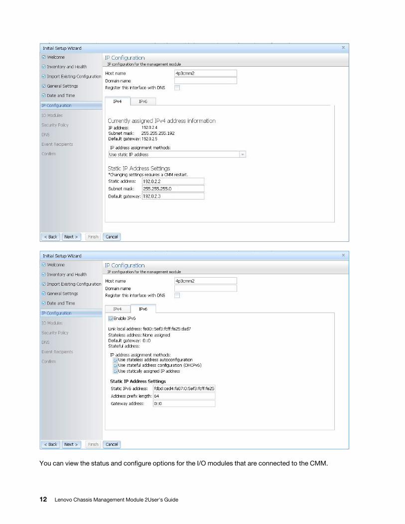
You can view the status and configure options for the I/O modules that are connected to the CMM.
12 Lenovo Chassis Management Module 2User's Guide
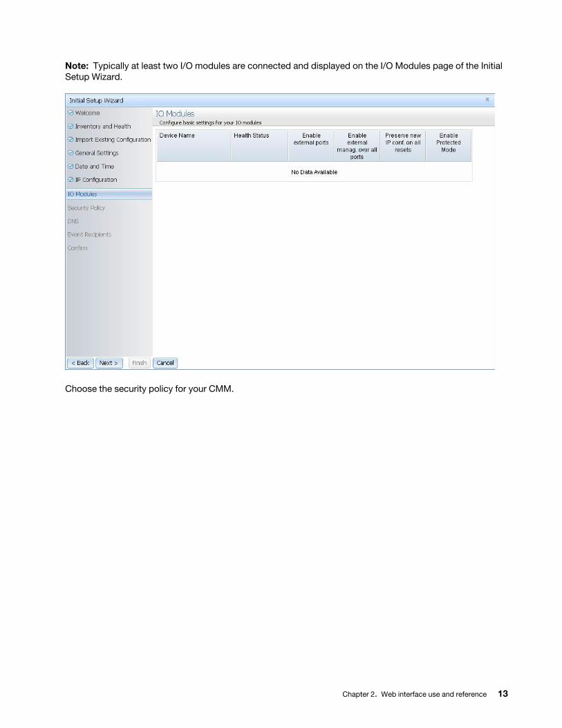
Note: Typically at least two I/O modules are connected and displayed on the I/O Modules page of the Initial Setup Wizard.
Choose the security policy for your CMM.
Chapter 2. Web interface use and reference 13
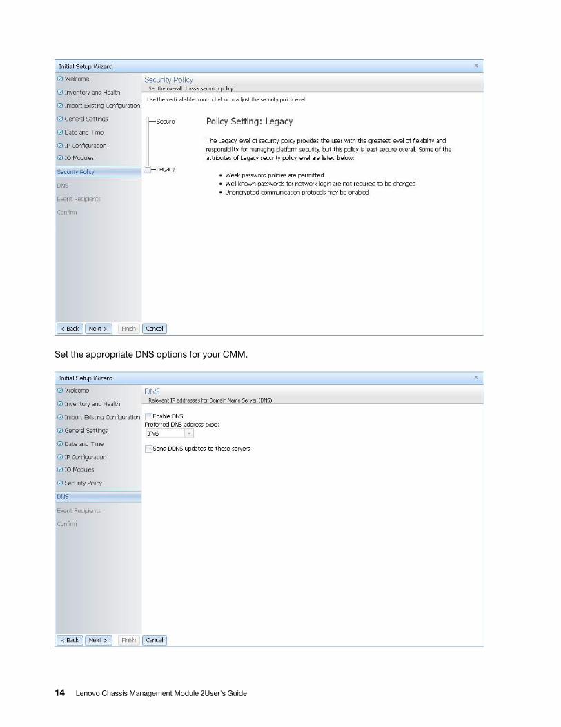
Set the appropriate DNS options for your CMM.
14 Lenovo Chassis Management Module 2User's Guide
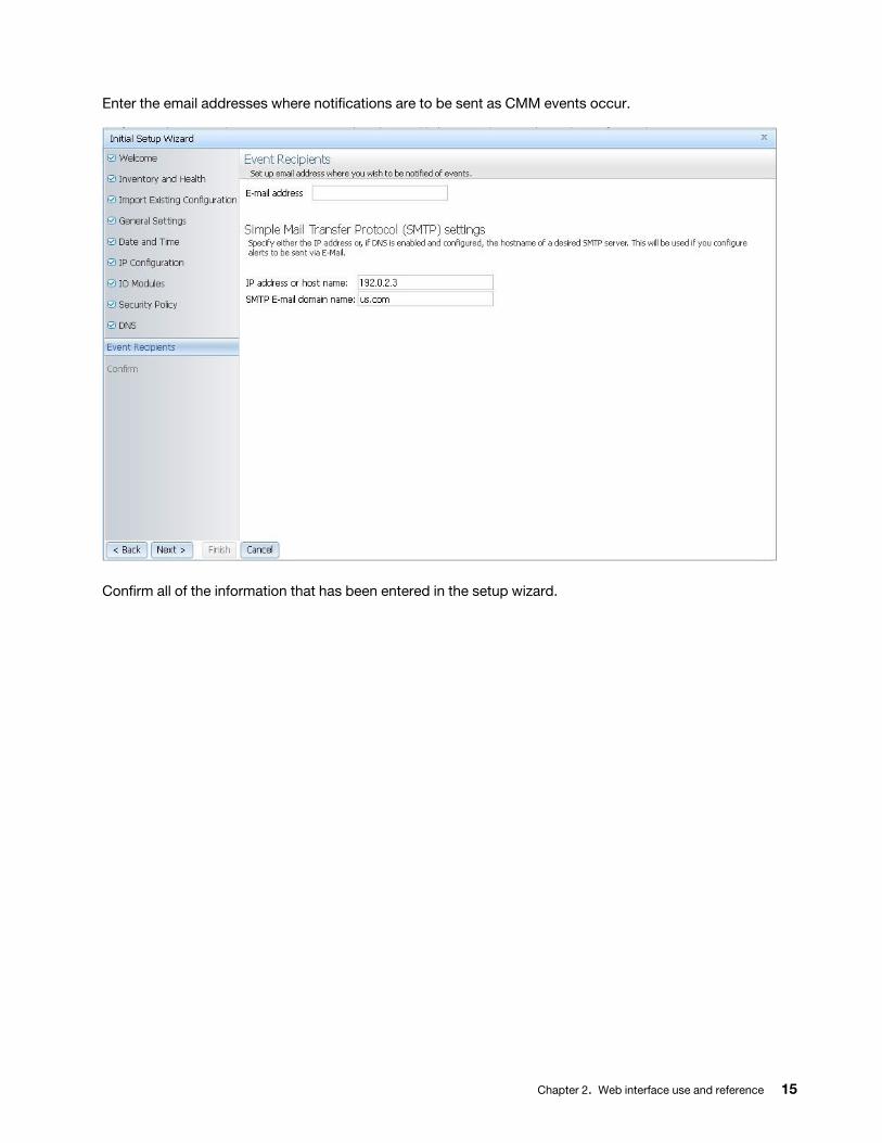
Enter the email addresses where notifications are to be sent as CMM events occur.
Confirm all of the information that has been entered in the setup wizard.
Chapter 2. Web interface use and reference 15
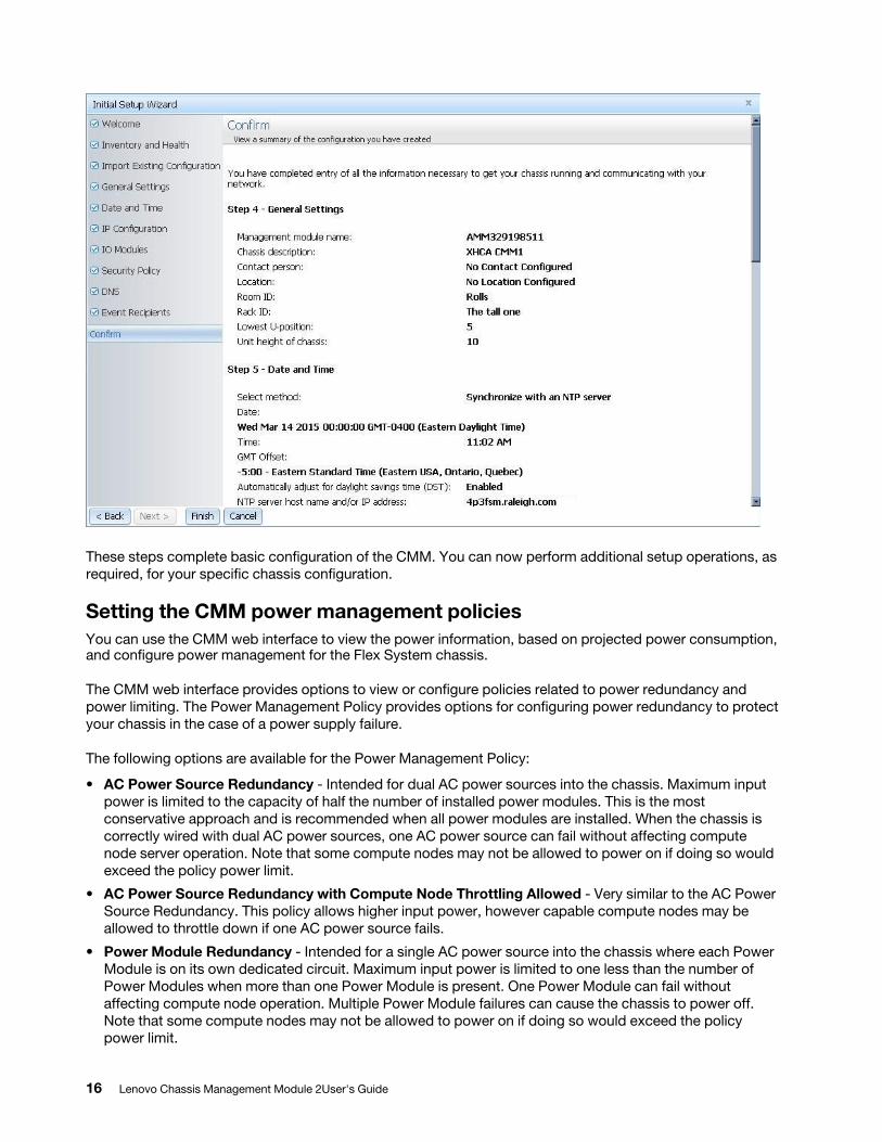
These steps complete basic configuration of the CMM. You can now perform additional setup operations, as required, for your specific chassis configuration.
Setting the CMM power management policiesYou can use the CMM web interface to view the power information, based on projected power consumption, and configure power management for the Flex System chassis.
The CMM web interface provides options to view or configure policies related to power redundancy and power limiting. The Power Management Policy provides options for configuring power redundancy to protect your chassis in the case of a power supply failure.
The following options are available for the Power Management Policy:
• AC Power Source Redundancy - Intended for dual AC power sources into the chassis. Maximum input power is limited to the capacity of half the number of installed power modules. This is the most conservative approach and is recommended when all power modules are installed. When the chassis is correctly wired with dual AC power sources, one AC power source can fail without affecting compute node server operation. Note that some compute nodes may not be allowed to power on if doing so would exceed the policy power limit.
• AC Power Source Redundancy with Compute Node Throttling Allowed - Very similar to the AC Power Source Redundancy. This policy allows higher input power, however capable compute nodes may be allowed to throttle down if one AC power source fails.
• Power Module Redundancy - Intended for a single AC power source into the chassis where each Power Module is on its own dedicated circuit. Maximum input power is limited to one less than the number of Power Modules when more than one Power Module is present. One Power Module can fail without affecting compute node operation. Multiple Power Module failures can cause the chassis to power off. Note that some compute nodes may not be allowed to power on if doing so would exceed the policy power limit.
16 Lenovo Chassis Management Module 2User's Guide
• Power Module Redundancy with Compute Nodes Throttling Allowed - Very similar to Power Module Redundancy. This policy allows higher input power; however, capable compute nodes may be allowed to throttle down if one Power Module fails.
• Basic Power Management - Maximum input power is higher than other policies and is limited only by the nameplate power of all the Power Modules combined. This is the least conservative approach, since it does not provide any protection for AC power source or Power Module failure. If any single power supply fails, compute node and/or chassis operation may be affected.
The Power Limiting/Capping Policy provides options to limit the total amount of power that the chassis and components are allowed to consume. The following options are available for the Power Limiting/Capping Policy:
• No Power Limiting - Maximum input power will be determined by the active Power Redundancy policy.
• Static Power Limiting - Sets an overall chassis limit on the maximum input power. In a situation where powering on a component would cause the limit to be exceeded, the component would not be permitted to power on.
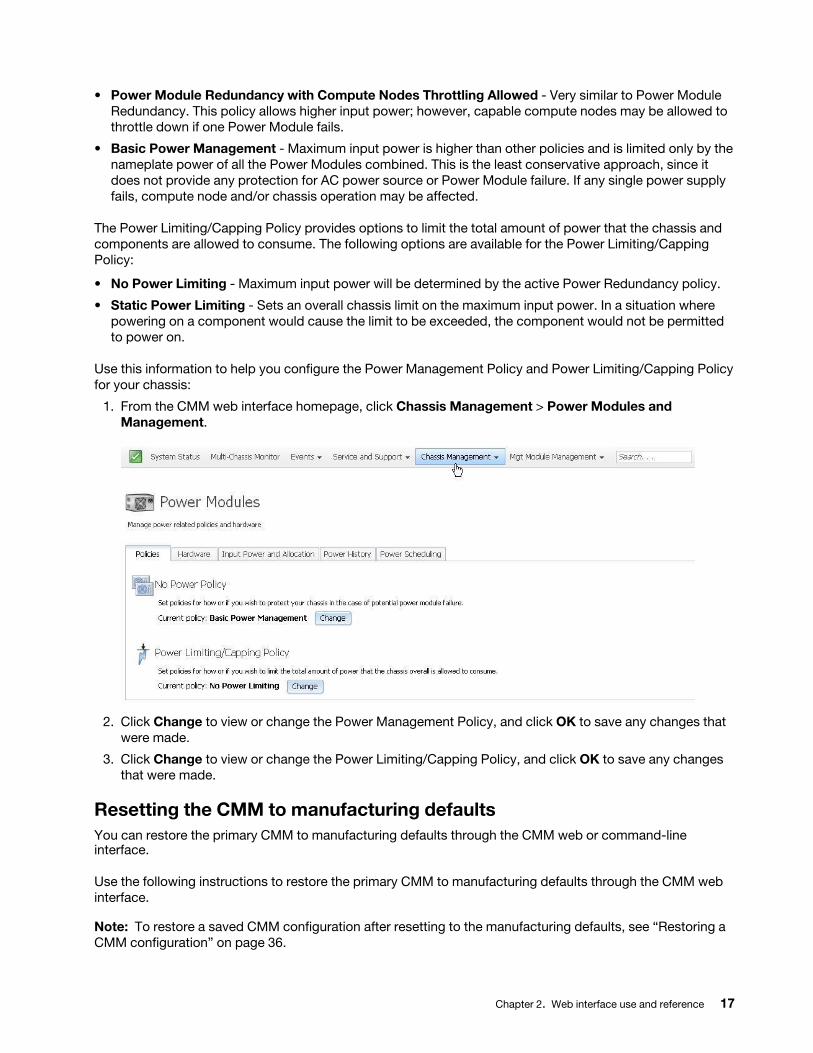
Use this information to help you configure the Power Management Policy and Power Limiting/Capping Policy for your chassis:
1. From the CMM web interface homepage, click Chassis Management > Power Modules and Management.
2. Click Change to view or change the Power Management Policy, and click OK to save any changes that were made.
3. Click Change to view or change the Power Limiting/Capping Policy, and click OK to save any changes that were made.
Resetting the CMM to manufacturing defaultsYou can restore the primary CMM to manufacturing defaults through the CMM web or command-line interface.
Use the following instructions to restore the primary CMM to manufacturing defaults through the CMM web interface.
Note: To restore a saved CMM configuration after resetting to the manufacturing defaults, see “Restoring a CMM configuration” on page 36.
Chapter 2. Web interface use and reference 17
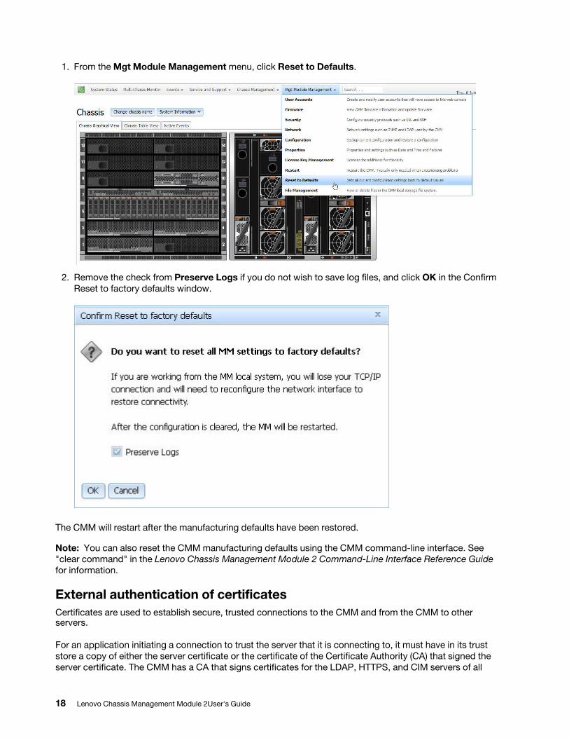
1. From the Mgt Module Management menu, click Reset to Defaults.
2. Remove the check from Preserve Logs if you do not wish to save log files, and click OK in the Confirm Reset to factory defaults window.
The CMM will restart after the manufacturing defaults have been restored.
Note: You can also reset the CMM manufacturing defaults using the CMM command-line interface. See "clear command" in the Lenovo Chassis Management Module 2 Command-Line Interface Reference Guide for information.
External authentication of certificatesCertificates are used to establish secure, trusted connections to the CMM and from the CMM to other servers.
For an application initiating a connection to trust the server that it is connecting to, it must have in its trust store a copy of either the server certificate or the certificate of the Certificate Authority (CA) that signed the server certificate. The CMM has a CA that signs certificates for the LDAP, HTTPS, and CIM servers of all
18 Lenovo Chassis Management Module 2User's Guide
systems management processors in a Flex System chassis. Some compute nodes, such as the x240 M5 compute node, can also create certificates that can be imported by the CMM. See the Integrated Management Module (IMM) documentation for your compute node for information and instructions.
You can create trust between your web browser and the HTTPS servers on the management processors in the chassis by importing the CA certificate into your web browser. Additionally, when you work with an external LDAP server, you can use the CMM web interface or CLI to configure either non-mutual (server only) or mutual certificate authentication.
The CA certificate in each Lenovo Flex System chassis is unique. You download CA certificates through the primary CMM in each chassis using the CMM web interface or CLI.
• In the CMM web interface, click Mgt Module Management > Security > SSL Servers and Certificates > CMM Externally Signed SSL Server Certificate and Bundled Chain of Trust. Select the certificate type and format, and click Save and Install Certificate.
• In the CLI, download the CA certificate into the CMM by using the sslcfg -dnld command (see "sslcfg command," in the Lenovo Chassis Management Module 2 Command-Line Interface Reference Guide, for additional information about command use).
The following illustration shows the certificate download window.
Chapter 2. Web interface use and reference 19
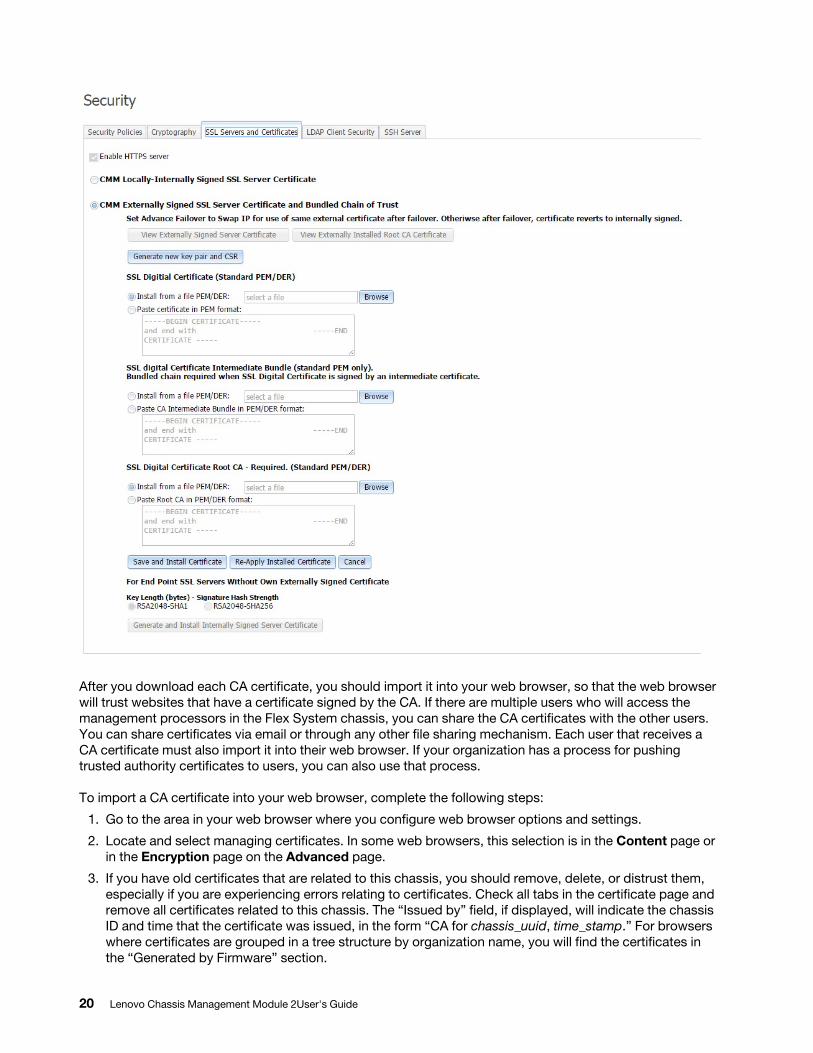
After you download each CA certificate, you should import it into your web browser, so that the web browser will trust websites that have a certificate signed by the CA. If there are multiple users who will access the management processors in the Flex System chassis, you can share the CA certificates with the other users. You can share certificates via email or through any other file sharing mechanism. Each user that receives a CA certificate must also import it into their web browser. If your organization has a process for pushing trusted authority certificates to users, you can also use that process.
To import a CA certificate into your web browser, complete the following steps:
1. Go to the area in your web browser where you configure web browser options and settings.
2. Locate and select managing certificates. In some web browsers, this selection is in the Content page or in the Encryption page on the Advanced page.
3. If you have old certificates that are related to this chassis, you should remove, delete, or distrust them, especially if you are experiencing errors relating to certificates. Check all tabs in the certificate page and remove all certificates related to this chassis. The “Issued by” field, if displayed, will indicate the chassis ID and time that the certificate was issued, in the form “CA for chassis_uuid, time_stamp.” For browsers where certificates are grouped in a tree structure by organization name, you will find the certificates in the “Generated by Firmware” section.
20 Lenovo Chassis Management Module 2User's Guide
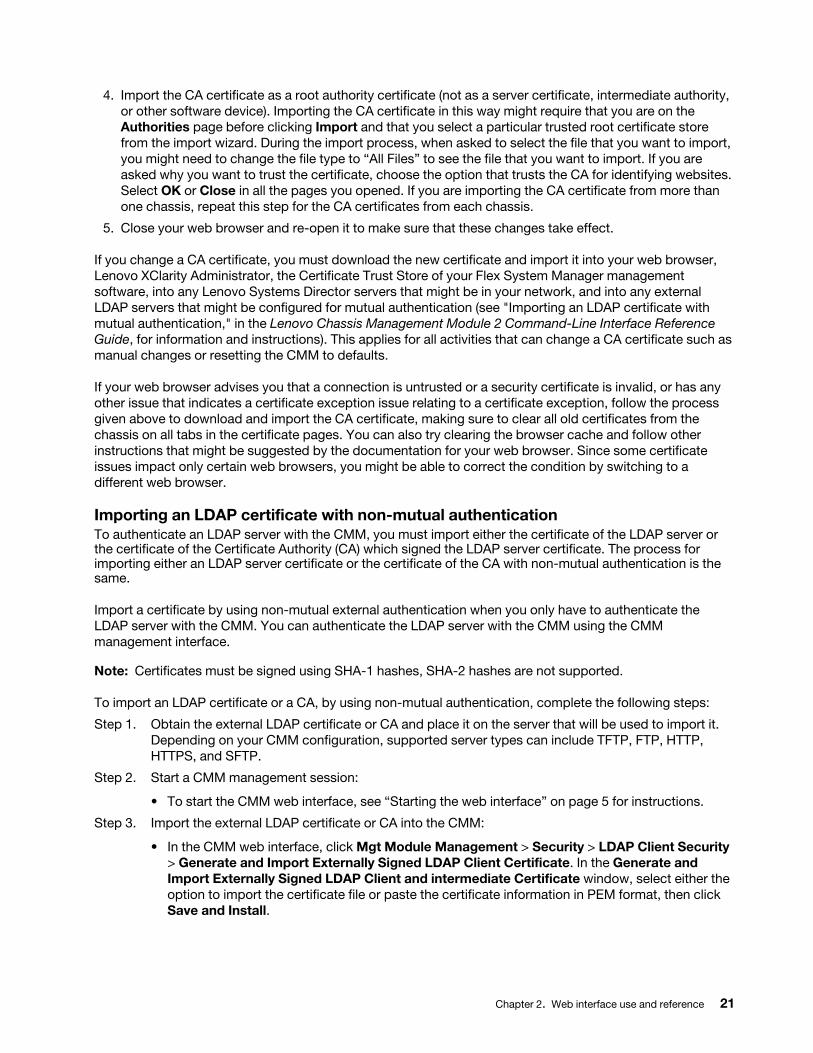
4. Import the CA certificate as a root authority certificate (not as a server certificate, intermediate authority, or other software device). Importing the CA certificate in this way might require that you are on the Authorities page before clicking Import and that you select a particular trusted root certificate store from the import wizard. During the import process, when asked to select the file that you want to import, you might need to change the file type to “All Files” to see the file that you want to import. If you are asked why you want to trust the certificate, choose the option that trusts the CA for identifying websites. Select OK or Close in all the pages you opened. If you are importing the CA certificate from more than one chassis, repeat this step for the CA certificates from each chassis.
5. Close your web browser and re-open it to make sure that these changes take effect.
If you change a CA certificate, you must download the new certificate and import it into your web browser, Lenovo XClarity Administrator, the Certificate Trust Store of your Flex System Manager management software, into any Lenovo Systems Director servers that might be in your network, and into any external LDAP servers that might be configured for mutual authentication (see "Importing an LDAP certificate with mutual authentication," in the Lenovo Chassis Management Module 2 Command-Line Interface Reference Guide, for information and instructions). This applies for all activities that can change a CA certificate such as manual changes or resetting the CMM to defaults.
If your web browser advises you that a connection is untrusted or a security certificate is invalid, or has any other issue that indicates a certificate exception issue relating to a certificate exception, follow the process given above to download and import the CA certificate, making sure to clear all old certificates from the chassis on all tabs in the certificate pages. You can also try clearing the browser cache and follow other instructions that might be suggested by the documentation for your web browser. Since some certificate issues impact only certain web browsers, you might be able to correct the condition by switching to a different web browser.
Importing an LDAP certificate with non-mutual authenticationTo authenticate an LDAP server with the CMM, you must import either the certificate of the LDAP server or the certificate of the Certificate Authority (CA) which signed the LDAP server certificate. The process for importing either an LDAP server certificate or the certificate of the CA with non-mutual authentication is the same.
Import a certificate by using non-mutual external authentication when you only have to authenticate the LDAP server with the CMM. You can authenticate the LDAP server with the CMM using the CMM management interface.
Note: Certificates must be signed using SHA-1 hashes, SHA-2 hashes are not supported.
To import an LDAP certificate or a CA, by using non-mutual authentication, complete the following steps:
Step 1. Obtain the external LDAP certificate or CA and place it on the server that will be used to import it. Depending on your CMM configuration, supported server types can include TFTP, FTP, HTTP, HTTPS, and SFTP.
Step 2. Start a CMM management session:
• To start the CMM web interface, see “Starting the web interface” on page 5 for instructions.
Step 3. Import the external LDAP certificate or CA into the CMM:
• In the CMM web interface, click Mgt Module Management > Security > LDAP Client Security > Generate and Import Externally Signed LDAP Client Certificate. In the Generate and Import Externally Signed LDAP Client and intermediate Certificate window, select either the option to import the certificate file or paste the certificate information in PEM format, then click Save and Install.
Chapter 2. Web interface use and reference 21
Importing an LDAP certificate with mutual authenticationImport certificates for mutual authentication when you need the external LDAP server to authenticate the CMM and the CMM to authenticate the external LDAP server.
There are two ways to establish mutual authentication between the CMM and an external LDAP server. When you use either method, you must also perform the steps for non-mutual authentication.
• Export the chassis Certificate Authority (CA) certificate and import it into the trust store for your external LDAP server. This allows mutual authentication between the LDAP server and all elements in the chassis that have their security configuration automatically provisioned.
• Export a certificate-signing request (CSR) from the CMM and have it signed by a Certificate Authority that the LDAP server already trusts. This method provides mutual authentication between only the CMM and the LDAP server.
Mutual authentication using CATo use the CMM certificate authority (CA) with an external LDAP server, you must import the CA certificate into the external LDAP server trust store. Up to three trusted certificates can be imported.
To establish mutual authentication using the CMM web interface, complete the following steps:1. Import the external LDAP server certificate or the CA chain that signed it into the CMM as an LDAP
trusted certificate, as described in “Importing an LDAP certificate with non-mutual authentication” on page 21.
2. Start a CMM web interface session. To start the CMM web interface, see “Starting the web interface” on page 5 for instructions.
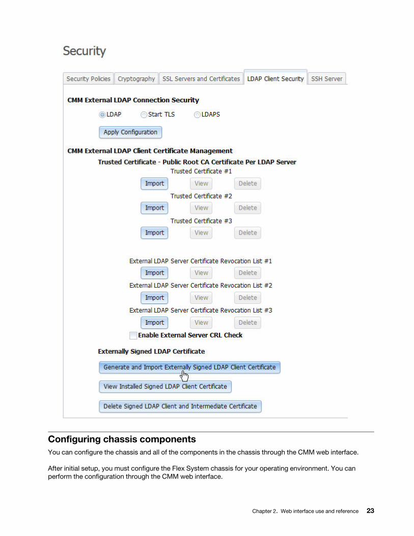
3. Make sure that secure LDAP is enabled by clicking Mgt Module Management > Security > LDAP Client Security and selecting LDAPS under the CMM External LDAP Connection Security heading.
4. Download the CMM CA to the specified server through the CMM web interface by clicking Mgt Module Management > Security > LDAP Client Security. Click Add in the Trusted Certificate - Public Root CA Certificate Per LDAP Server section under CMM External LDAP Client Certificate Management; then, select the option to either import the certificate file, or paste the certificate in PEM format and click Apply. Depending on your CMM configuration, supported server types can include TFTP, FTP, HTTP, HTTPS, and SFTP.
Note: The CMM does not support external LDAP servers that use the certificate authority SHA256 to sign their certificates. See the documentation for your LDAP server for more information.
Mutual authentication of CSRTo establish mutual authentication between the CMM and an external LDAP server, have the CMM certificate-signing request (CSR) signed by an outside Certificate Authority (CA) using the CMM management interface.
To generate a CSR on the CMM and get it signed by using the CMM web interface, complete the following steps:
1. Start a CMM web interface session.2. Click Mgt Module Management > Security and select the LDAP Client Security tab.3. Select the option to either import, or paste certificate information, then click Apply Import.
22 Lenovo Chassis Management Module 2User's Guide
Configuring chassis componentsYou can configure the chassis and all of the components in the chassis through the CMM web interface.
After initial setup, you must configure the Flex System chassis for your operating environment. You can perform the configuration through the CMM web interface.
Chapter 2. Web interface use and reference 23

The chassis automatically detects components such as compute nodes, storage nodes, I/O modules, power supplies, fan modules, fan distribution cards, and fan logic modules that are installed and stores the vital product data (VPD) for each component. When the chassis is started, the CMM automatically configures the remote management port of the CMM so that you can configure and manage Lenovo Flex System nodes.
To communicate with network resources and with the I/O modules in the chassis, you must configure IP addresses for the CMM and I/O modules. You can configure CMM and I/O module IP addresses using the web interface. You can also configure the I/O modules by an external I/O-module port that is enabled through the CMM, using a Telnet interface, a serial connection, or a web browser. See the documentation that comes with each I/O module for information and instructions.
To communicate with nodes for functions such as deploying an operating system or application over a network, you must also configure at least one external (in-band) port on an Ethernet switch in one of the I/O bays of the Flex System chassis.
Note: If a pass-thru module instead of an Ethernet I/O module is installed in an I/O bay, you might have to configure the network switch that the pass-thru module is connected to. See the documentation that comes with the pass-thru module and the network switch for information and instructions.
Important: After the initial chassis setup has been completed and all nodes have been configured, be sure that the CMM has the proper firmware installed before installing additional nodes. Some nodes require specific firmware levels. To download firmware updates for your CMM, go to http:// datacentersupport.lenovo.com to display the matrix of downloadable files for the CMM.
Attention: Installing the wrong firmware update might cause the CMM to malfunction. Before you install a firmware update, read any readme and change history files that are provided with the downloaded update. These files contain important information about the update and the procedure for installing the update, including any special procedure for updating from an early firmware version to the latest version.
You can configure the chassis or individual components from the Chassis Management menu in the CMM web interface.
The following illustration shows the Chassis Management page, which contains configuration options for the chassis and components in the chassis.
Setting the chassis air filter reminderYou can set a reminder to change the chassis air filter through the CMM web interface.
If your chassis has the optional chassis air filter installed, be sure to configure the air filter reminder for your operating environment. You can set the reminder for different intervals according to the amount of air contaminates in the chassis operating environment. The reminder is sent to the event log in the form of an event.
24 Lenovo Chassis Management Module 2User's Guide
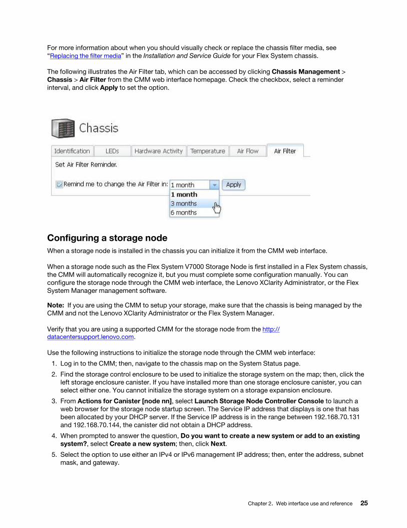
For more information about when you should visually check or replace the chassis filter media, see “Replacing the filter media” in the Installation and Service Guide for your Flex System chassis.
The following illustrates the Air Filter tab, which can be accessed by clicking Chassis Management > Chassis > Air Filter from the CMM web interface homepage. Check the checkbox, select a reminder interval, and click Apply to set the option.
Configuring a storage nodeWhen a storage node is installed in the chassis you can initialize it from the CMM web interface.
When a storage node such as the Flex System V7000 Storage Node is first installed in a Flex System chassis, the CMM will automatically recognize it, but you must complete some configuration manually. You can configure the storage node through the CMM web interface, the Lenovo XClarity Administrator, or the Flex System Manager management software.
Note: If you are using the CMM to setup your storage, make sure that the chassis is being managed by the CMM and not the Lenovo XClarity Administrator or the Flex System Manager.
Verify that you are using a supported CMM for the storage node from the http:// datacentersupport.lenovo.com.
Use the following instructions to initialize the storage node through the CMM web interface:
1. Log in to the CMM; then, navigate to the chassis map on the System Status page.
2. Find the storage control enclosure to be used to initialize the storage system on the map; then, click the left storage enclosure canister. If you have installed more than one storage enclosure canister, you can select either one. You cannot initialize the storage system on a storage expansion enclosure.
3. From Actions for Canister [node nn], select Launch Storage Node Controller Console to launch a web browser for the storage node startup screen. The Service IP address that displays is one that has been allocated by your DHCP server. If the Service IP address is in the range between 192.168.70.131 and 192.168.70.144, the canister did not obtain a DHCP address.
4. When prompted to answer the question, Do you want to create a new system or add to an existing system?, select Create a new system; then, click Next.
5. Select the option to use either an IPv4 or IPv6 management IP address; then, enter the address, subnet mask, and gateway.
Chapter 2. Web interface use and reference 25
6. Click Finish to set the management IP address for the system. The system initialization will begin and might take several minutes to complete.
7. After the system initialization is complete, the setup wizard will be launched. The setup wizard will help you through the configuration steps for basic system settings such as time and date, system name, and hardware detection and verification.
8. Log in to the storage node.
9. Review the software license agreement. You must accept the agreement before you can continue.
10. Enter the system name and a new superuser password.
From this point you have the option to use the setup wizard to configure more settings such as notifications and storage configuration. If you are not ready to complete more configuration steps, go to configuration tasks in the management user interface to complete the configuration at a later time.
It is recommended that you upgrade to the most current level of software after installing the storage node. Refer to the http://datacentersupport.lenovo.com for the latest information about software upgrades.
For more information about configuring your storage node, see Using the Chassis Management Module to set up your system in the Flex System V7000 Storage Node Installation Guide.
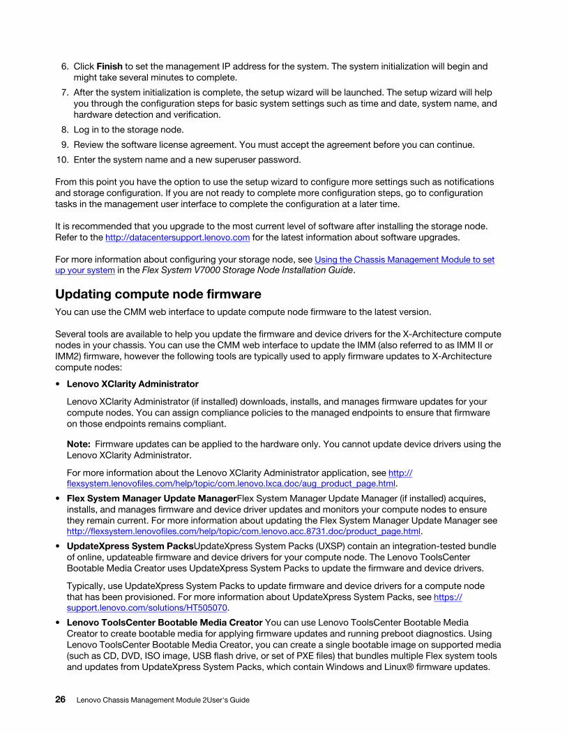
Updating compute node firmwareYou can use the CMM web interface to update compute node firmware to the latest version.
Several tools are available to help you update the firmware and device drivers for the X-Architecture compute nodes in your chassis. You can use the CMM web interface to update the IMM (also referred to as IMM II or IMM2) firmware, however the following tools are typically used to apply firmware updates to X-Architecture compute nodes:
• Lenovo XClarity Administrator
Lenovo XClarity Administrator (if installed) downloads, installs, and manages firmware updates for your compute nodes. You can assign compliance policies to the managed endpoints to ensure that firmware on those endpoints remains compliant.
Note: Firmware updates can be applied to the hardware only. You cannot update device drivers using the Lenovo XClarity Administrator.
For more information about the Lenovo XClarity Administrator application, see http:// flexsystem.lenovofiles.com/help/topic/com.lenovo.lxca.doc/aug_product_page.html.
• Flex System Manager Update ManagerFlex System Manager Update Manager (if installed) acquires, installs, and manages firmware and device driver updates and monitors your compute nodes to ensure they remain current. For more information about updating the Flex System Manager Update Manager see http://flexsystem.lenovofiles.com/help/topic/com.lenovo.acc.8731.doc/product_page.html.
• UpdateXpress System PacksUpdateXpress System Packs (UXSP) contain an integration-tested bundle of online, updateable firmware and device drivers for your compute node. The Lenovo ToolsCenter Bootable Media Creator uses UpdateXpress System Packs to update the firmware and device drivers.
Typically, use UpdateXpress System Packs to update firmware and device drivers for a compute node that has been provisioned. For more information about UpdateXpress System Packs, see https:// support.lenovo.com/solutions/HT505070.
• Lenovo ToolsCenter Bootable Media Creator You can use Lenovo ToolsCenter Bootable Media Creator to create bootable media for applying firmware updates and running preboot diagnostics. Using Lenovo ToolsCenter Bootable Media Creator, you can create a single bootable image on supported media (such as CD, DVD, ISO image, USB flash drive, or set of PXE files) that bundles multiple Flex system tools and updates from UpdateXpress System Packs, which contain Windows and Linux® firmware updates.
26 Lenovo Chassis Management Module 2User's Guide
Typically, Lenovo ToolsCenter Bootable Media Creator is used for the initial setup of a compute node. For more information about the Bootable Media Creator, see http://support.lenovo.com/downloads/DS117986.
• Integrated management module II (IMM2) You can use the IMM2 to update some types of compute node firmware. For more information about the IMM2, see https://download.lenovo.com/ibmdl/pub/pc/ pccbbs/thinkservers/imm_userguide.pdf (you might need to register to access this content).
Another way to update firmware and device drivers is through the CMM web interface. You can use the CMM web interface to launch a remote IMM web session and update the IMM firmware for each X-Architecture compute node in your Flex System chassis. You must update the IMM firmware for each X-Architecture compute node individually.
Note: Remote compute node IMM sessions from the CMM are not supported by all compute nodes types, including all Power Systems compute nodes. See the documentation for your compute node for information.
If no user accounts have been manually set up for the IMM of the compute node you are trying to access, the connection to that IMM must be completed using the CMM user ID and password. For an IMM to communicate with the compute node Advanced Settings Utility (ASU) and UpdateXpress System Pack Installer (UXSPI) programs, a local user account must be set up for the compute node IMM. This local account is not included in an IMM configuration backup. For information about using the compute node IMM interface, see the compute node or IMM documentation.
Attention: Installing the wrong firmware or device-driver update might cause the compute node to malfunction. Before you install a firmware or device-driver update, read any readme and change history files provided with the update. These files contain important information about the update and the procedure for installing the update, including any special procedures for updating from an early firmware or device-driver version to the latest version.
Note: Follow the instructions in the readme file that comes with the firmware update. For additional information about updating firmware for the Lenovo Flex System, see the Firmware Update Best Practices Guide at (you might need to register to access this content).
Note: You can access the compute node IMM CLI using a CMM SOL session (see “Starting an SOL session”, in the Lenovo Chassis Management Module 2 Command-Line Interface Reference Guide).
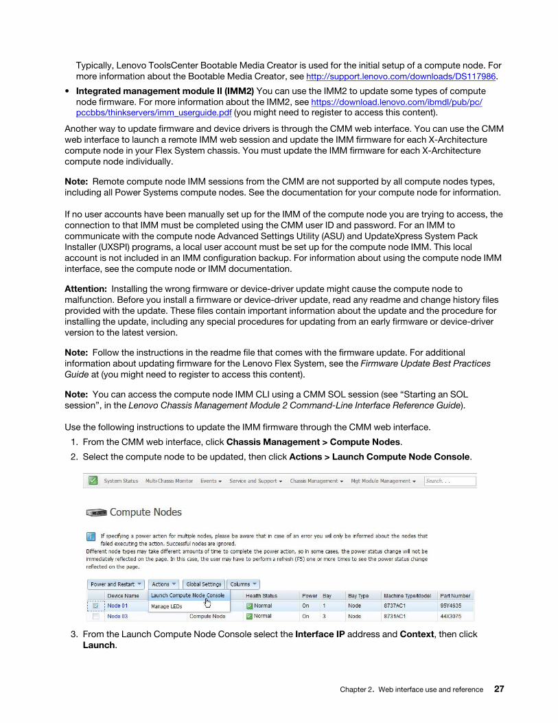
Use the following instructions to update the IMM firmware through the CMM web interface.
1. From the CMM web interface, click Chassis Management > Compute Nodes.
2. Select the compute node to be updated, then click Actions > Launch Compute Node Console.
3. From the Launch Compute Node Console select the Interface IP address and Context, then click Launch.
Chapter 2. Web interface use and reference 27
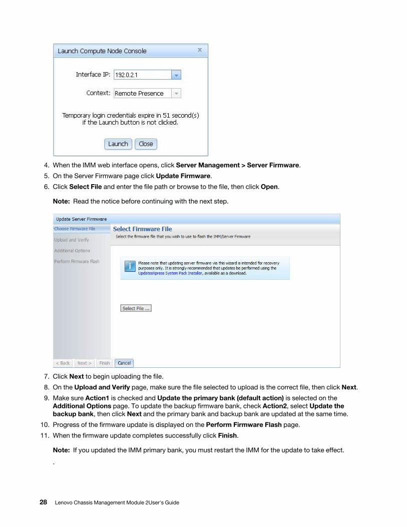
4. When the IMM web interface opens, click Server Management > Server Firmware.
5. On the Server Firmware page click Update Firmware.
6. Click Select File and enter the file path or browse to the file, then click Open.
Note: Read the notice before continuing with the next step.
7. Click Next to begin uploading the file.
8. On the Upload and Verify page, make sure the file selected to upload is the correct file, then click Next.
9. Make sure Action1 is checked and Update the primary bank (default action) is selected on the Additional Options page. To update the backup firmware bank, check Action2, select Update the backup bank, then click Next and the primary bank and backup bank are updated at the same time.
10. Progress of the firmware update is displayed on the Perform Firmware Flash page.
11. When the firmware update completes successfully click Finish.
Note: If you updated the IMM primary bank, you must restart the IMM for the update to take effect.
.
28 Lenovo Chassis Management Module 2User's Guide
Important: To avoid problems and to maintain system performance, make sure the UEFI code, IMM2 firmware, and diagnostic firmware levels are consistent for all compute nodes in the chassis.
For additional information about updating firmware and device drivers, see UEFI Compliant Firmware on Lenovo System x and BladeCenter Servers, the Lenovo Flex System Quick Start Guides, and the Firmware Update Best Practices Guide athttps://support.lenovo.com/solutions/HT116912 (you might need to register to access this content).
User authority managementYou can create users and manage user authority through the CMM web interface.
Users are assigned authority levels according to user permission groups that are set up for the CMM. Users with Supervisor command authority can execute all commands. Users with Operator command authority are restricted to read-only access.
Notes:
• CMM user accounts are used to log in to the service processor interfaces for compute nodes.
• If a user account becomes locked, click Mgt Module Management > User Accounts to access the User Accounts page. A locked user account has Locked in the State column. To unlock an account, select the user account, and click Unlock.
• If your CMM is managed by an optional management node and you are unable to connect to the CMM from a user account because it has been locked, you can unlock it through the Lenovo XClarity Administrator or Flex System Manager management software web interface. For information about using the Lenovo XClarity Administrator, see http://flexsystem.lenovofiles.com/help/topic/com.lenovo.lxca.doc/ aug_product_page.html. See "CMM access problems,"in the Flex System Manager Management Software Troubleshooting and Support Guide, for information about Flex System Manager command use.
• Do not store any sensitive information in the CMM file system. Data in the CMM web server directory or subdirectories is accessible by unauthenticated users.
You can create a user and change user authority levels from the User Accounts page. The CMM supports a maximum of 84 user accounts. When creating a new user, remember that the same user ID and password are used for all methods of connecting to the CMM, and that the password is case sensitive while the user ID is not case sensitive.
There are two available methods of creating a new user: username&password (default) or username &email. Switch between the two in Global Login Settings in “CMM management options” on page 82.
Notes: Passwords must meet all the following criteria:
• Only consisting of the following characters : A-Z, a-z, 0-9, ~`!@#$%^&*()-+={}[]|:;"'<>,?/
• Not including space
• Containing at least one alphabet and one number
• Containing at least two of the following:
– At least one upper-case alphabet
– At least one lower-case alphabet
– At least one special character (~`!@#$%^&*()-+={}[]|:;"'<>,?/)
• Not being exactly the same or reserve of the user name
• Not consisting of more than two consecutive occurrences of the same character (for example, a password combination is allowed to contain ee or @@ but not eee or @@@)
Chapter 2. Web interface use and reference 29
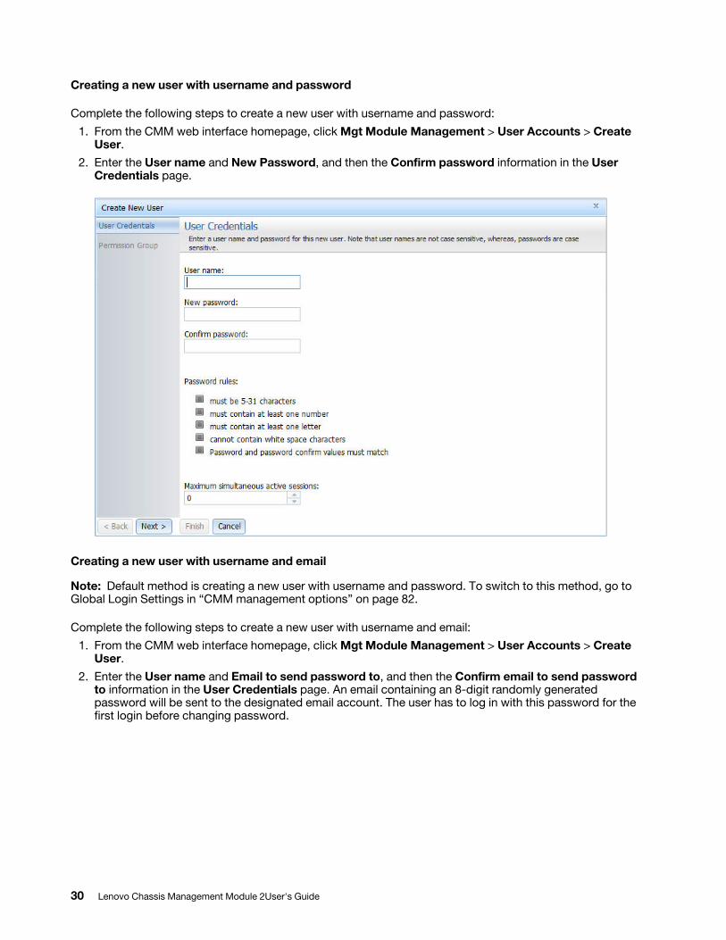
Creating a new user with username and password
Complete the following steps to create a new user with username and password:
1. From the CMM web interface homepage, click Mgt Module Management > User Accounts > Create User.
2. Enter the User name and New Password, and then the Confirm password information in the User Credentials page.
Creating a new user with username and email
Note: Default method is creating a new user with username and password. To switch to this method, go to Global Login Settings in “CMM management options” on page 82.
Complete the following steps to create a new user with username and email:1. From the CMM web interface homepage, click Mgt Module Management > User Accounts > Create
User.2. Enter the User name and Email to send password to, and then the Confirm email to send password
to information in the User Credentials page. An email containing an 8-digit randomly generated password will be sent to the designated email account. The user has to log in with this password for the first login before changing password.
30 Lenovo Chassis Management Module 2User's Guide
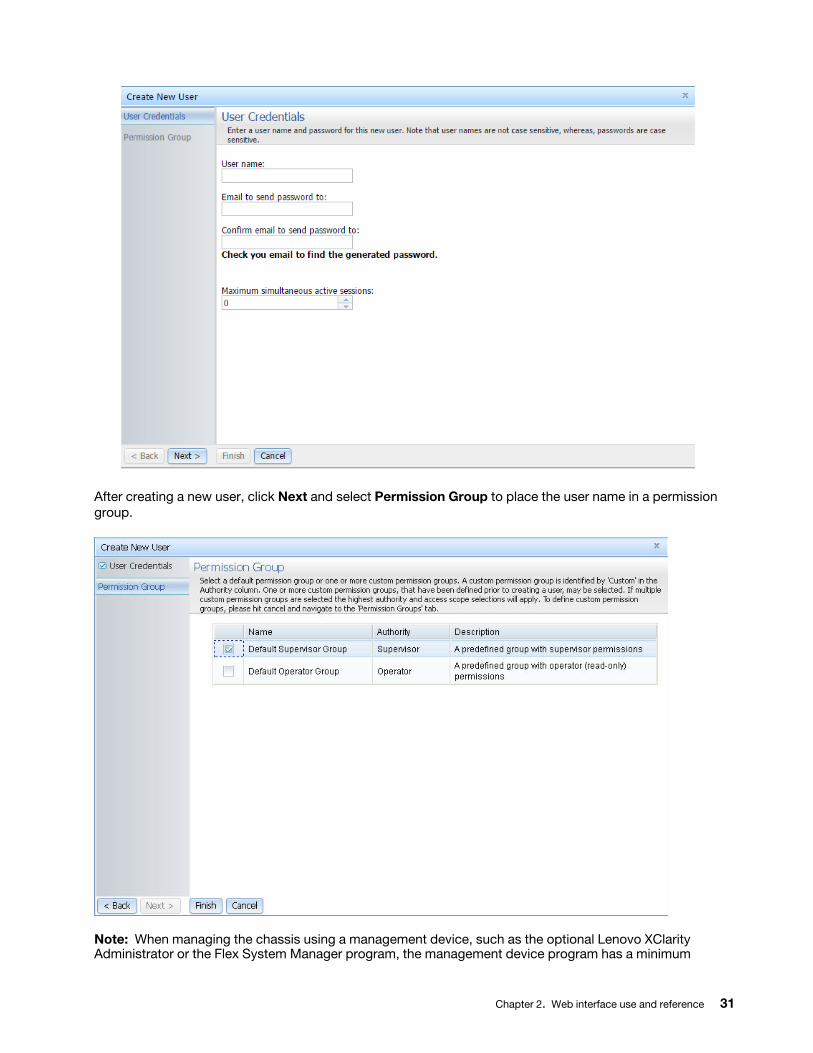
After creating a new user, click Next and select Permission Group to place the user name in a permission group.
Note: When managing the chassis using a management device, such as the optional Lenovo XClarity Administrator or the Flex System Manager program, the management device program has a minimum
Chapter 2. Web interface use and reference 31
authentication logging timeout of 3600 seconds. If the value of the CMM authentication logging timeout is greater than 3600, the value of the CMM authentication logging timeout is used.
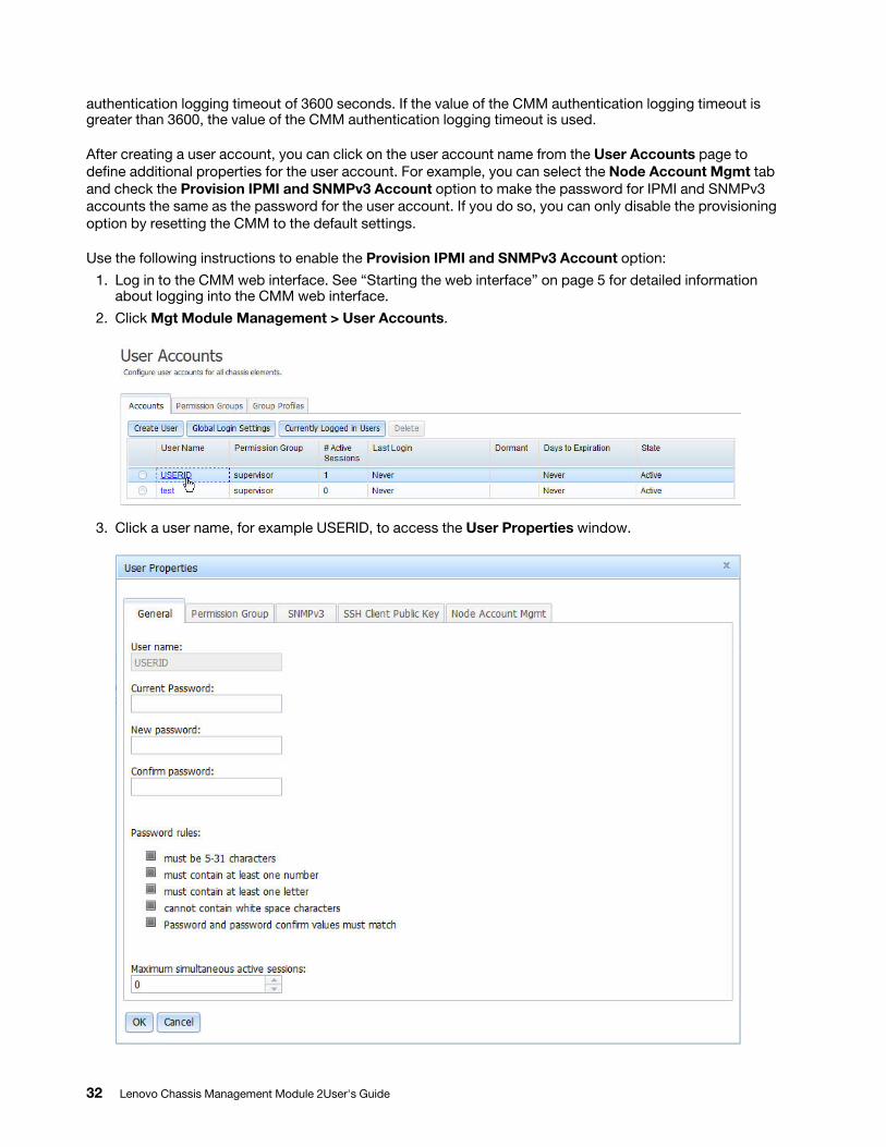
After creating a user account, you can click on the user account name from the User Accounts page to define additional properties for the user account. For example, you can select the Node Account Mgmt tab and check the Provision IPMI and SNMPv3 Account option to make the password for IPMI and SNMPv3 accounts the same as the password for the user account. If you do so, you can only disable the provisioning option by resetting the CMM to the default settings.
Use the following instructions to enable the Provision IPMI and SNMPv3 Account option:1. Log in to the CMM web interface. See “Starting the web interface” on page 5 for detailed information
about logging into the CMM web interface.2. Click Mgt Module Management > User Accounts.
3. Click a user name, for example USERID, to access the User Properties window.
32 Lenovo Chassis Management Module 2User's Guide
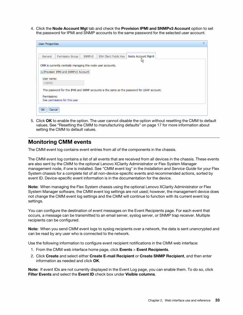
4. Click the Node Account Mgt tab and check the Provision IPMI and SNMPv3 Account option to set the password for IPMI and SNMP accounts to the same password for the selected user account.
5. Click OK to enable the option. The user cannot disable the option without resetting the CMM to default values. See “Resetting the CMM to manufacturing defaults” on page 17 for more information about setting the CMM to default values.
Monitoring CMM eventsThe CMM event log contains event entries from all of the components in the chassis.
The CMM event log contains a list of all events that are received from all devices in the chassis. These events are also sent by the CMM to the optional Lenovo XClarity Administrator or Flex System Manager management node, if one is installed. See "CMM event log" in the Installation and Service Guide for your Flex System chassis for a complete list of all non-device-specific events and recommended actions, sorted by event ID. Device-specific event information is in the documentation for the device.
Note: When managing the Flex System chassis using the optional Lenovo XClarity Administrator or Flex System Manager software, the CMM event log settings are not used; however, the management device does not change the CMM event log settings and the CMM will continue to function with its current event log settings.
You can configure the destination of event messages on the Event Recipients page. For each event that occurs, a message can be transmitted to an email server, syslog server, or SNMP trap receiver. Multiple recipients can be configured.
Note: When you send CMM event logs to syslog recipients over a network, the data is sent unencrypted and can be read by any user who is connected to the network.
Use the following information to configure event recipient notifications in the CMM web interface:
1. From the CMM web interface home page, click Events > Event Recipients.
2. Click Create and select either Create E-mail Recipient or Create SNMP Recipient, and then enter information as needed and click OK.
Note: If event IDs are not currently displayed in the Event Log page, you can enable them. To do so, click Filter Events and select the Event ID check box under Visible columns.
Chapter 2. Web interface use and reference 33
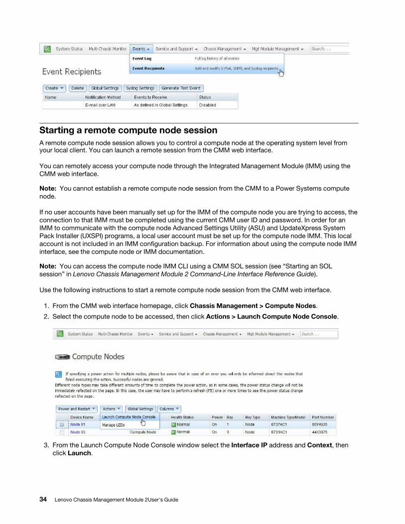
Starting a remote compute node sessionA remote compute node session allows you to control a compute node at the operating system level from your local client. You can launch a remote session from the CMM web interface.
You can remotely access your compute node through the Integrated Management Module (IMM) using the CMM web interface.
Note: You cannot establish a remote compute node session from the CMM to a Power Systems compute node.
If no user accounts have been manually set up for the IMM of the compute node you are trying to access, the connection to that IMM must be completed using the current CMM user ID and password. In order for an IMM to communicate with the compute node Advanced Settings Utility (ASU) and UpdateXpress System Pack Installer (UXSPI) programs, a local user account must be set up for the compute node IMM. This local account is not included in an IMM configuration backup. For information about using the compute node IMM interface, see the compute node or IMM documentation.
Note: You can access the compute node IMM CLI using a CMM SOL session (see “Starting an SOL session” in Lenovo Chassis Management Module 2 Command-Line Interface Reference Guide).
Use the following instructions to start a remote compute node session from the CMM web interface.
1. From the CMM web interface homepage, click Chassis Management > Compute Nodes.
2. Select the compute node to be accessed, then click Actions > Launch Compute Node Console.
3. From the Launch Compute Node Console window select the Interface IP address and Context, then click Launch.
34 Lenovo Chassis Management Module 2User's Guide
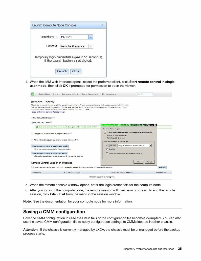
4. When the IMM web interface opens, select the preferred client, click Start remote control in single- user mode, then click OK if prompted for permission to open the viewer.
5. When the remote console window opens, enter the login credentials for the compute node.
6. After you log in to the compute node, the remote session will then be in progress. To end the remote session, click File > Exit from the menu in the session window.
Note: See the documentation for your compute node for more information.
Saving a CMM configurationSave the CMM configuration in case the CMM fails or the configuration file becomes corrupted. You can also use the saved CMM configuration file to apply configuration settings to CMMs located in other chassis.
Attention: If the chassis is currently managed by LXCA, the chassis must be unmanaged before the backup process starts.
Chapter 2. Web interface use and reference 35
Save the CMM configuration in case the CMM fails or the configuration file becomes corrupted. You can also use the saved CMM configuration file to apply configuration settings to CMMs located in other chassis.
Saving the configuration allows you to restore the saved settings if a CMM is replaced or if configuration information is corrupted or lost. You must save the CMM configuration before replacing a CMM or restoring a CMM to the manufacturing default configuration, if you intend to restore the configuration.
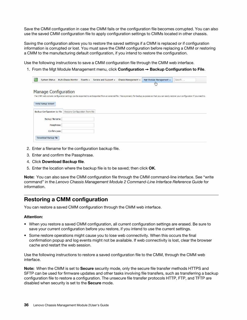
Use the following instructions to save a CMM configuration file through the CMM web interface.
1. From the Mgt Module Management menu, click Configuration ➙ Backup Configuration to File.
2. Enter a filename for the configuration backup file.
3. Enter and confirm the Passphrase.
4. Click Download Backup file.
5. Enter the location where the backup file is to be saved; then click OK.
Note: You can also save the CMM configuration file through the CMM command-line interface. See “write command” in the Lenovo Chassis Management Module 2 Command-Line Interface Reference Guide for information.
Restoring a CMM configurationYou can restore a saved CMM configuration through the CMM web interface.
Attention:
• When you restore a saved CMM configuration, all current configuration settings are erased. Be sure to save your current configuration before you restore, if you intend to use the current settings.
• Some restore operations might cause you to lose web connectivity. When this occurs the final confirmation popup and log events might not be available. If web connectivity is lost, clear the browser cache and restart the web session.
Use the following instructions to restore a saved configuration file to the CMM, through the CMM web interface.
Note: When the CMM is set to Secure security mode, only the secure file transfer methods HTTPS and SFTP can be used for firmware updates and other tasks involving file transfers, such as transferring a backup configuration file to restore a configuration. The unsecure file transfer protocols HTTP, FTP, and TFTP are disabled when security is set to the Secure mode.
36 Lenovo Chassis Management Module 2User's Guide
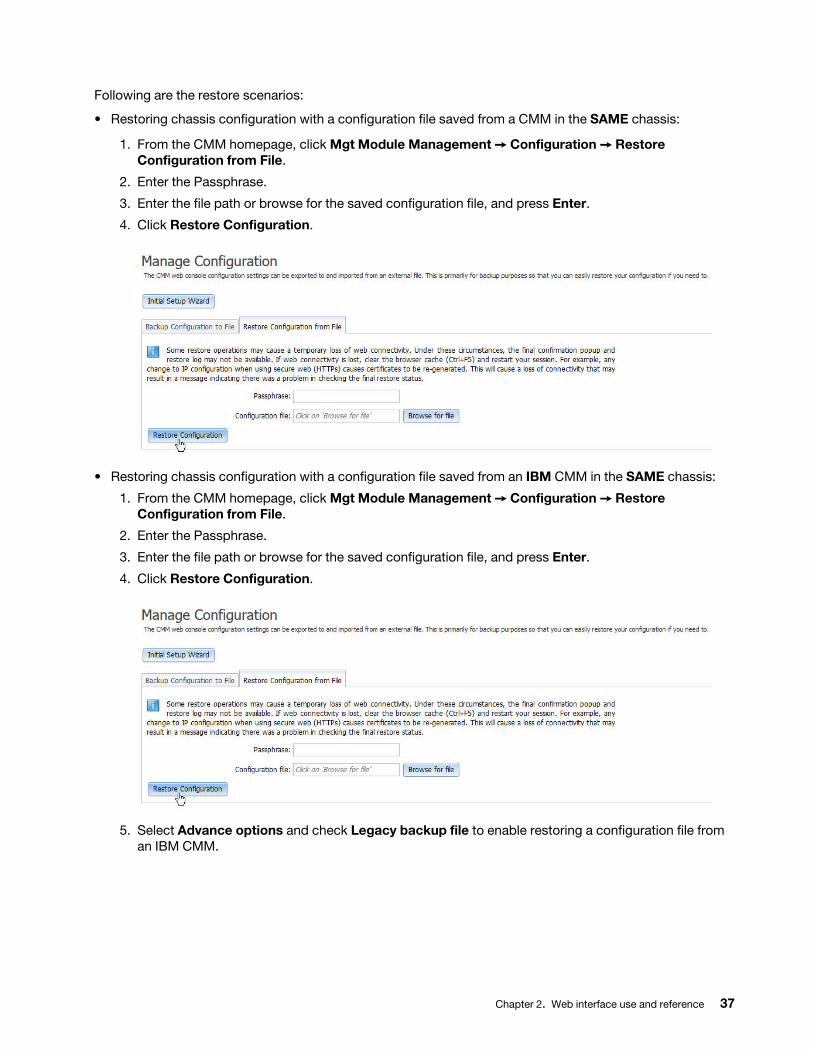
Following are the restore scenarios:
• Restoring chassis configuration with a configuration file saved from a CMM in the SAME chassis:
1. From the CMM homepage, click Mgt Module Management ➙ Configuration ➙ Restore Configuration from File.
2. Enter the Passphrase.
3. Enter the file path or browse for the saved configuration file, and press Enter.
4. Click Restore Configuration.
• Restoring chassis configuration with a configuration file saved from an IBM CMM in the SAME chassis:
1. From the CMM homepage, click Mgt Module Management ➙ Configuration ➙ Restore Configuration from File.
2. Enter the Passphrase.
3. Enter the file path or browse for the saved configuration file, and press Enter.
4. Click Restore Configuration.
5. Select Advance options and check Legacy backup file to enable restoring a configuration file from an IBM CMM.
Chapter 2. Web interface use and reference 37
Note: You can also restore a saved CMM configuration through the CMM command-line interface. See "read command" in the Lenovo Chassis Management Module 2 Command-Line Interface Reference Guide for information.
• Restoring chassis configuration with a configuration file saved from a DIFFERENT chassis:
When deploying CMMs to multiple chassis, you can apply the saved backup configuration file to the CMMs without having to configure each one individually. If static IP addresses are used, each CMM must have a unique address and only one CMM at a time can be added onto the network for discovery. Adding more than one CMM to the network without a unique IP address assignment for each results in IP address conflicts.
Starting from build number 1AON24A, configuration backup file is a tar.gz archive file that includes 4 files. One of those files is Config.bkp file, which is used in previous CMM versions.
In order to successfully apply the backup configuration file, you must open the saved CMM backup configuration file (.bkp) in a text editor, such as Notepad, and change the IP address to a unique IP address for the CMM that is to be configured. Use the following to change the IP address in a saved CMM backup configuration file (.bkp), and apply it to a CMM.
1. Navigate to the location where the CMM backup configuration file is saved and open the file with a text editor, such as Notepad.
2. Locate the IPv4 address of the primary CMM in the Primary Management Module IPv4 Configuration section of the Network Interfaces information. The IPv4 address used in the example is 192.168.1.1 (highlighted in bold in the following code block).
Note: The entry beginning with ifconfig -T mm[P] -eth0... is shown with a line break after -s 255 -s 255.255.255.0. When this command is entered, the entire entry must all be on one line.
############################# ### Network Interfaces #############################
ifconfig -T mm[P] -eth0 -dn
### Primary Management Module IPv4 Configuration
ifconfig -T mm[P] -eth0 -i 192.168.1.1 -g 0.0.0.0 -s 255.255.255.0 -n MM5CF3FC25D969
ifconfig -T mm[P] -eth0 -c dthens
3. Change the Primary Management Module IPv4 Configuration IP address to a unique address and save the file.
38 Lenovo Chassis Management Module 2User's Guide
4. Open the web interface for the CMM that is being added, and from the Mgt Module Management menu, click Configuration ➙ Restore Configuration from File.
5. Enter and confirm the Passphrase.
6. Browse for and select the CMM backup configuration file (.bkp) to use, and click Open.
Booting from the standby CMMYou can boot from the standby CMM through the CMM web interface.
If you perform this operation from the primary CMM, it causes a failover to the standby as the active CMM for the chassis.
Use the following instructions to boot from the standby CMM:
1. From the CMM web interface homepage, click Mgt Module Management > Restart.
2. Select Restart and switch to standby in the Restart Management Module window, and click OK.
Note: If a Flex System chassis is set up for redundant CMM operation and both CMMs experience an unrecoverable failure, the chassis will attempt to switch control between the CMMs indefinitely. If this condition occurs, replace one CMM to return the chassis to operation or replace both CMMs to return the chassis to redundant operation. Depending on how each CMM failed, you might need to configure the replacement CMM or restore its configuration from a backup, if one is available. A failure of both CMMs might be an indication of other problems with the Flex System chassis; make sure that the chassis is operating properly before replacing either CMM. See Troubleshooting chassis for information about diagnosing problems with a Flex System chassis.
Enabling the CMM floating IP addressWhen you have two CMMs installed in a Flex System chassis, you can enable the floating IP address option to always access the primary CMM no matter how the IP addresses are specified for the primary and standby CMMs.
You can enable the primary CMM floating IP address through the CMM web interface. When you enable the floating IP address, the connection will always resolve to the primary CMM.
Use this information to enable the floating IP address for the primary and standby CMMs.
1. From the CMM web interface homepage, click Mgt Module Management > Network > Ethernet.
2. On the Ethernet Configuration page, select either IPv4 or IPv6 for your system; then, under Configure IP address settings select the option to use a static IP address.
3. Click Mgt Module Management > Properties > Advanced Failover and enable the advance failover option.
4. Enter the floating IP address to be used for the CMMs.
Note: You can also set the CMM floating IP address using the CMM command-line interface. See "ifconfig command" in the Lenovo Chassis Management Module 2 Command-Line Interface Reference Guide for information.
CMM portsThe Lenovo Chassis Management Module 2 modules use a variety of TCP/IP ports for communication. This topic lists these ports and indicates the ones that are fixed or can be changed by an administrator. You need to make sure that your network allows communications through these ports for the Lenovo Chassis Management Module 2 modules to function and communicate correctly.
Chapter 2. Web interface use and reference 39
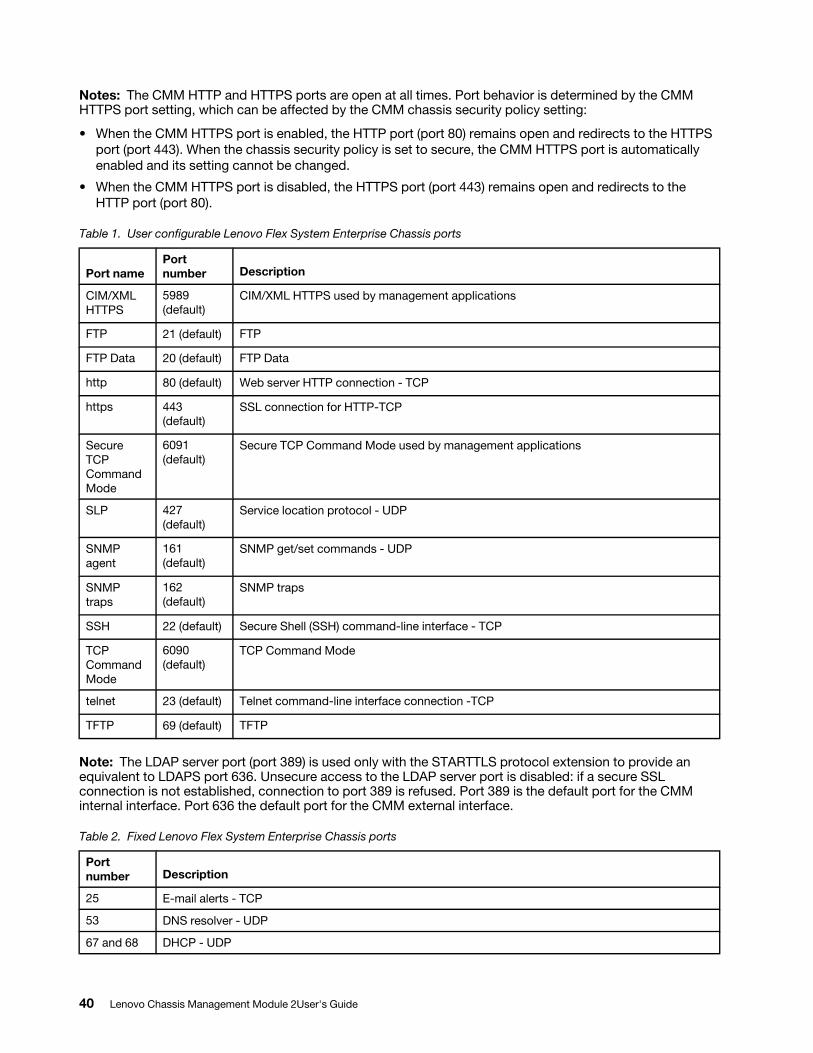
Notes: The CMM HTTP and HTTPS ports are open at all times. Port behavior is determined by the CMM HTTPS port setting, which can be affected by the CMM chassis security policy setting:
• When the CMM HTTPS port is enabled, the HTTP port (port 80) remains open and redirects to the HTTPS port (port 443). When the chassis security policy is set to secure, the CMM HTTPS port is automatically enabled and its setting cannot be changed.
• When the CMM HTTPS port is disabled, the HTTPS port (port 443) remains open and redirects to the HTTP port (port 80).
Table 1. User configurable Lenovo Flex System Enterprise Chassis ports
Port namePort number Description
CIM/XML HTTPS
5989 (default)
CIM/XML HTTPS used by management applications
FTP 21 (default) FTP
FTP Data 20 (default) FTP Data
http 80 (default) Web server HTTP connection - TCP
https 443 (default)
SSL connection for HTTP-TCP
Secure TCP Command Mode
6091 (default)
Secure TCP Command Mode used by management applications
SLP 427 (default)
Service location protocol - UDP
SNMP agent
161 (default)
SNMP get/set commands - UDP
SNMP traps
162 (default)
SNMP traps
SSH 22 (default) Secure Shell (SSH) command-line interface - TCP
TCP Command Mode
6090 (default)
TCP Command Mode
telnet 23 (default) Telnet command-line interface connection -TCP
TFTP 69 (default) TFTP
Note: The LDAP server port (port 389) is used only with the STARTTLS protocol extension to provide an equivalent to LDAPS port 636. Unsecure access to the LDAP server port is disabled: if a secure SSL connection is not established, connection to port 389 is refused. Port 389 is the default port for the CMM internal interface. Port 636 the default port for the CMM external interface.
Table 2. Fixed Lenovo Flex System Enterprise Chassis ports
Port number Description
25 E-mail alerts - TCP
53 DNS resolver - UDP
67 and 68 DHCP - UDP
40 Lenovo Chassis Management Module 2User's Guide
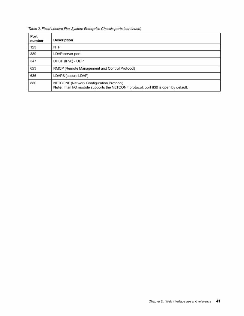
Table 2. Fixed Lenovo Flex System Enterprise Chassis ports (continued)
Port number Description
123 NTP
389 LDAP server port
547 DHCP (IPv6) - UDP
623 RMCP (Remote Management and Control Protocol)
636 LDAPS (secure LDAP)
830 NETCONF (Network Configuration Protocol) Note: If an I/O module supports the NETCONF protocol, port 830 is open by default.
Chapter 2. Web interface use and reference 41

42 Lenovo Chassis Management Module 2User's Guide
Chapter 3. CMM web interface overview
Use this information to help you understand the structure and content of the CMM web-based graphical user interface.
Descriptions of the CMM web interface pages and information about the structure and content of the CMM web interface are in this topic. There are also descriptions of CMM web interface features that can be accessed by users, according to their assigned roles or authority levels (see “Web interface pages and user roles” on page 43). See the CMM online help for information about using the CMM web interface to perform selected functions.
Web interface pages and user rolesChassis user authority can be managed in the CMM web interface.
Users are assigned authority levels according to user permission groups that are set up for the CMM.
Note: LDAP authority levels are not supported by the CMM web interface.
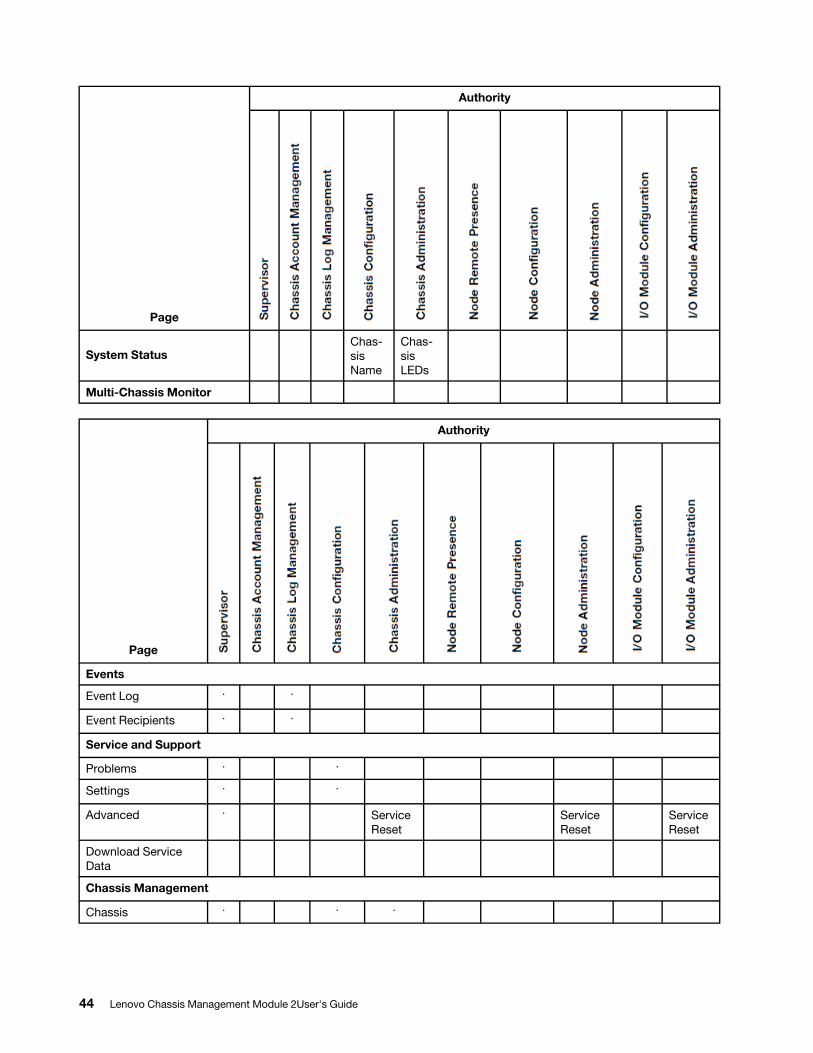
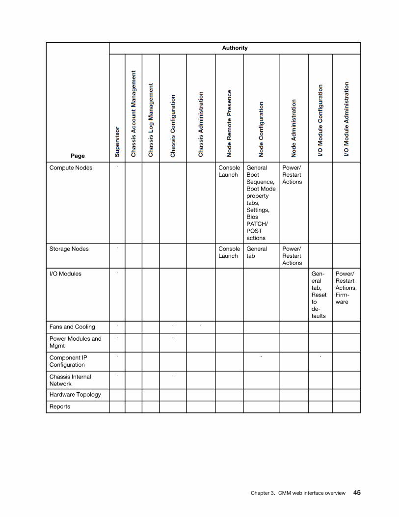
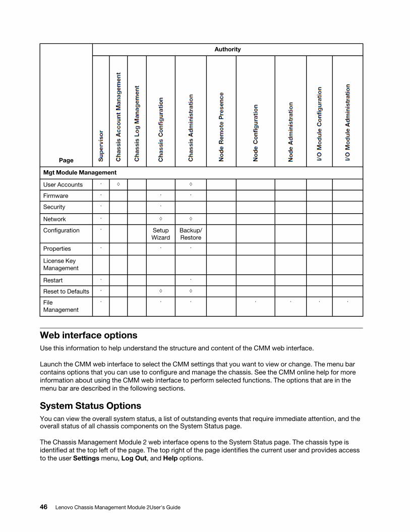
The table that follows contains the CMM web interface pages and the authorities or roles required to change information on these pages. The authorities listed in the table only apply to changing information or performing a task specific to that page. Viewing information on a page does not require any specific authority.
Before using the table, observe the following guidelines:
• A dot (·) indicates that all fields or options on the page are accessible, and it requires only one authority at a time.
• A diamond (◊) indicates that a page requires a combination of two or more authorities. For example, the “Mgt Module Management” is available to a user with the Supervisor authority and to a user with both the Chassis Account Management and Chassis Configuration authorities.
• Text in a cell indicates that there are specific fields or options that are not accessible.
• An empty cell indicates that the page is read-only.
© Copyright Lenovo 2016, 2020 43
Page
Authority
System StatusChas-sis Name
Chas-sis LEDs
Multi-Chassis Monitor
Page
Authority
Events
Event Log · ·
Event Recipients · ·
Service and Support
Problems · ·
Settings · ·
Advanced · Service Reset
Service Reset
Service Reset
Download Service Data
Chassis Management
Chassis · · ·
44 Lenovo Chassis Management Module 2User's Guide
Page
Authority
Compute Nodes · Console Launch
General Boot Sequence, Boot Mode property tabs, Settings, Bios PATCH/ POST actions
Power/ Restart Actions
Storage Nodes · Console Launch
General tab
Power/ Restart Actions
I/O Modules · Gen-eral tab, Reset to de-faults
Power/ Restart Actions, Firm-ware
Fans and Cooling · · ·
Power Modules and Mgmt
· ·
Component IP Configuration
· · ·
Chassis Internal Network
· ·
Hardware Topology
Reports
Chapter 3. CMM web interface overview 45
Page
Authority
Mgt Module Management
User Accounts · ◊ ◊
Firmware · · ·
Security · ·
Network · ◊ ◊
Configuration · Setup Wizard
Backup/ Restore
Properties · · ·
License Key Management
Restart · ·
Reset to Defaults · ◊ ◊
File Management
· · · · · · ·
Web interface optionsUse this information to help understand the structure and content of the CMM web interface.
Launch the CMM web interface to select the CMM settings that you want to view or change. The menu bar contains options that you can use to configure and manage the chassis. See the CMM online help for more information about using the CMM web interface to perform selected functions. The options that are in the menu bar are described in the following sections.
System Status OptionsYou can view the overall system status, a list of outstanding events that require immediate attention, and the overall status of all chassis components on the System Status page.
The Chassis Management Module 2 web interface opens to the System Status page. The chassis type is identified at the top left of the page. The top right of the page identifies the current user and provides access to the user Settings menu, Log Out, and Help options.
46 Lenovo Chassis Management Module 2User's Guide
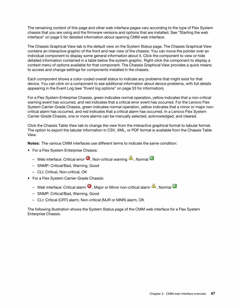
The remaining content of this page and other web interface pages vary according to the type of Flex System chassis that you are using and the firmware versions and options that are installed. See “Starting the web interface” on page 5 for detailed information about opening CMM web interface.
The Chassis Graphical View tab is the default view on the System Status page. The Chassis Graphical View contains an interactive graphic of the front and rear view of the chassis. You can move the pointer over an individual component to display some general information about it. Click the component to view or hide detailed information contained in a table below the system graphic. Right-click the component to display a context menu of options available for that component. The Chassis Graphical View provides a quick means to access and change settings for components installed in the chassis.
Each component shows a color-coded overall status to indicate any problems that might exist for that device. You can click on a component to see additional information about device problems, with full details appearing in the Event Log (see “Event log options” on page 53 for information).
For a Flex System Enterprise Chassis, green indicates normal operation, yellow indicates that a non-critical warning event has occurred, and red indicates that a critical error event has occurred. For the Lenovo Flex System Carrier-Grade Chassis, green indicates normal operation, yellow indicates that a minor or major non- critical alarm has occurred, and red indicates that a critical alarm has occurred. In a Lenovo Flex System Carrier-Grade Chassis, one or more alarms can be manually selected, acknowledged, and cleared.
Click the Chassis Table View tab to change the view from the interactive graphical format to tabular format. The option to export the tabular information in CSV, XML, or PDF format is available from the Chassis Table View.
Notes: The various CMM interfaces use different terms to indicate the same condition:
• For a Flex System Enterprise Chassis:
– Web interface: Critical error , Non-critical warning , Normal
– SNMP: Critical/Bad, Warning, Good
– CLI: Critical, Non-critical, OK
• For a Flex System Carrier-Grade Chassis:
– Web interface: Critical alarm , Major or Minor non-critical alarm , Normal
– SNMP: Critical/Bad, Warning, Good
– CLI: Critical (CRT) alarm, Non-critical (MJR or MNR) alarm, OK
The following illustration shows the System Status page of the CMM web interface for a Flex System Enterprise Chassis.
Chapter 3. CMM web interface overview 47
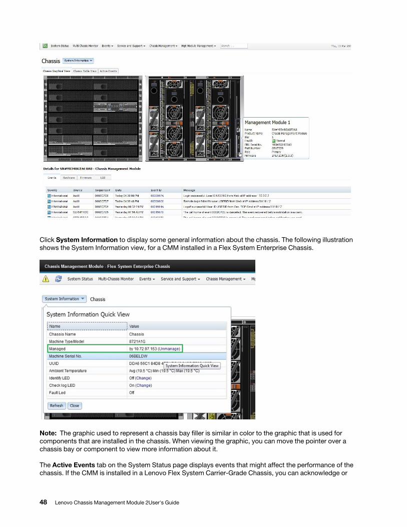
Click System Information to display some general information about the chassis. The following illustration shows the System Information view, for a CMM installed in a Flex System Enterprise Chassis.
Note: The graphic used to represent a chassis bay filler is similar in color to the graphic that is used for components that are installed in the chassis. When viewing the graphic, you can move the pointer over a chassis bay or component to view more information about it.
The Active Events tab on the System Status page displays events that might affect the performance of the chassis. If the CMM is installed in a Lenovo Flex System Carrier-Grade Chassis, you can acknowledge or
48 Lenovo Chassis Management Module 2User's Guide
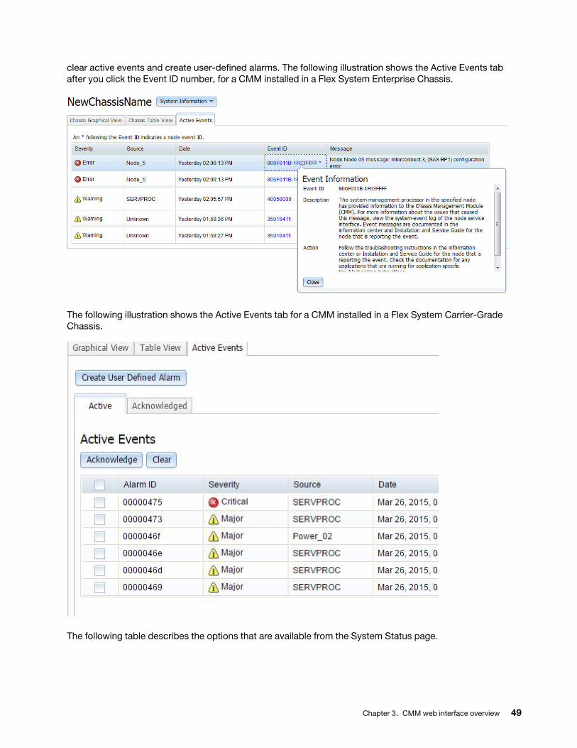
clear active events and create user-defined alarms. The following illustration shows the Active Events tab after you click the Event ID number, for a CMM installed in a Flex System Enterprise Chassis.
The following illustration shows the Active Events tab for a CMM installed in a Flex System Carrier-Grade Chassis.
The following table describes the options that are available from the System Status page.
Chapter 3. CMM web interface overview 49
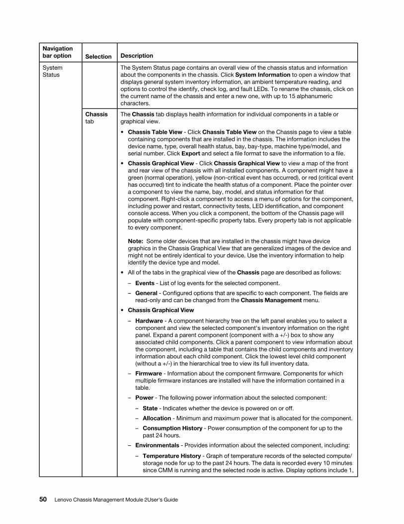
Navigation bar option Selection Description
System Status
The System Status page contains an overall view of the chassis status and information about the components in the chassis. Click System Information to open a window that displays general system inventory information, an ambient temperature reading, and options to control the identify, check log, and fault LEDs. To rename the chassis, click on the current name of the chassis and enter a new one, with up to 15 alphanumeric characters.
Chassis tab
The Chassis tab displays health information for individual components in a table or graphical view.
• Chassis Table View - Click Chassis Table View on the Chassis page to view a table containing components that are installed in the chassis. The information includes the device name, type, overall health status, bay, bay-type, machine type/model, and serial number. Click Export and select a file format to save the information to a file.
• Chassis Graphical View - Click Chassis Graphical View to view a map of the front and rear view of the chassis with all installed components. A component might have a green (normal operation), yellow (non-critical event has occurred), or red (critical event has occurred) tint to indicate the health status of a component. Place the pointer over a component to view the name, bay, model, and status information for that component. Right-click a component to access a menu of options for the component, including power and restart, connectivity tests, LED identification, and component console access. When you click a component, the bottom of the Chassis page will populate with component-specific property tabs. Every property tab is not applicable to every component.
Note: Some older devices that are installed in the chassis might have device graphics in the Chassis Graphical View that are generalized images of the device and might not be entirely identical to your device. Use the inventory information to help identify the device type and model.
• All of the tabs in the graphical view of the Chassis page are described as follows:
– Events - List of log events for the selected component.
– General - Configured options that are specific to each component. The fields are read-only and can be changed from the Chassis Management menu.
• Chassis Graphical View
– Hardware - A component hierarchy tree on the left panel enables you to select a component and view the selected component's inventory information on the right panel. Expand a parent component (component with a +/-) box to show any associated child components. Click a parent component to view information about the component, including a table that contains the child components and inventory information about each child component. Click the lowest level child component (without a +/-) in the hierarchical tree to view its full inventory data.
– Firmware - Information about the component firmware. Components for which multiple firmware instances are installed will have the information contained in a table.
– Power - The following power information about the selected component:
– State - Indicates whether the device is powered on or off.
– Allocation - Minimum and maximum power that is allocated for the component.
– Consumption History - Power consumption of the component for up to the past 24 hours.
– Environmentals - Provides information about the selected component, including:
– Temperature History - Graph of temperature records of the selected compute/ storage node for up to the past 24 hours. The data is recorded every 10 minutes since CMM is running and the selected node is active. Display options include 1,
50 Lenovo Chassis Management Module 2User's Guide
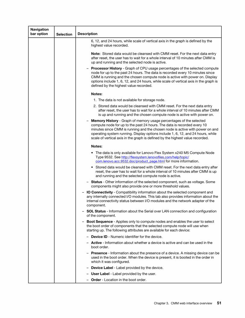
Navigation bar option Selection Description
6, 12, and 24 hours, while scale of vertical axis in the graph is defined by the highest value recorded.
Note: Stored data would be cleansed with CMM reset. For the next data entry after reset, the user has to wait for a whole interval of 10 minutes after CMM is up and running and the selected node is active.
– Processor History - Graph of CPU usage percentages of the selected compute node for up to the past 24 hours. The data is recorded every 10 minutes since CMM is running and the chosen compute node is active with power on. Display options include 1, 6, 12, and 24 hours, while scale of vertical axis in the graph is defined by the highest value recorded.
Notes:
1. The data is not available for storage node.
2. Stored data would be cleansed with CMM reset. For the next data entry after reset, the user has to wait for a whole interval of 10 minutes after CMM is up and running and the chosen compute node is active with power on.
– Memory History - Graph of memory usage percentages of the selected compute node for up to the past 24 hours. The data is recorded every 10 minutes since CMM is running and the chosen node is active with power on and operating system running. Display options include 1, 6, 12, and 24 hours, while scale of vertical axis in the graph is defined by the highest value recorded.
Notes:
• The data is only available for Lenovo Flex System x240 M5 Compute Node Type 9532. See http://flexsystem.lenovofiles.com/help/topic/ com.lenovo.acc.9532.doc/product_page.html for more information.
• Stored data would be cleansed with CMM reset. For the next data entry after reset, the user has to wait for a whole interval of 10 minutes after CMM is up and running and the selected compute node is active.
– Status - Other information of the selected component, such as voltage. Some components might also provide one or more threshold values.
– IO Connectivity - Compatibility information about the selected component and any internally connected I/O modules. This tab also provides information about the internal connectivity status between I/O modules and the network adapter of the component.
– SOL Status - Information about the Serial over LAN connection and configuration of the component.
– Boot Sequence - Applies only to compute nodes and enables the user to select the boot order of components that the selected compute node will use when starting up. The following attributes are available for each device:
– Device ID - Numeric identifier for the device.
– Active - Information about whether a device is active and can be used in the boot order.
– Presence - Information about the presence of a device. A missing device can be used in the boot order. When the device is present, it is booted in the order in which it was configured.
– Device Label - Label provided by the device.
– User Label - Label provided by the user.
– Order - Location in the boot order.
Chapter 3. CMM web interface overview 51
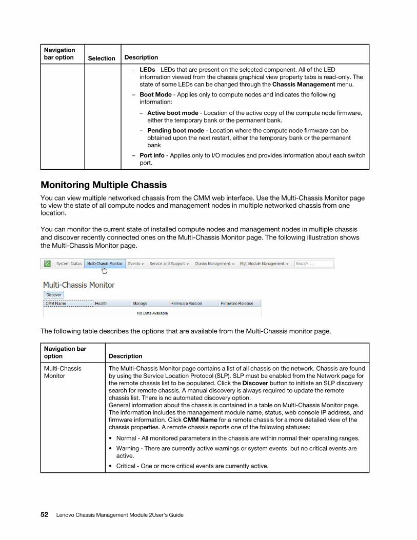
Navigation bar option Selection Description
– LEDs - LEDs that are present on the selected component. All of the LED information viewed from the chassis graphical view property tabs is read-only. The state of some LEDs can be changed through the Chassis Management menu.
– Boot Mode - Applies only to compute nodes and indicates the following information:
– Active boot mode - Location of the active copy of the compute node firmware, either the temporary bank or the permanent bank.
– Pending boot mode - Location where the compute node firmware can be obtained upon the next restart, either the temporary bank or the permanent bank
– Port info - Applies only to I/O modules and provides information about each switch port.
Monitoring Multiple ChassisYou can view multiple networked chassis from the CMM web interface. Use the Multi-Chassis Monitor page to view the state of all compute nodes and management nodes in multiple networked chassis from one location.
You can monitor the current state of installed compute nodes and management nodes in multiple chassis and discover recently connected ones on the Multi-Chassis Monitor page. The following illustration shows the Multi-Chassis Monitor page.
The following table describes the options that are available from the Multi-Chassis monitor page.
Navigation bar option Description
Multi-Chassis Monitor
The Multi-Chassis Monitor page contains a list of all chassis on the network. Chassis are found by using the Service Location Protocol (SLP). SLP must be enabled from the Network page for the remote chassis list to be populated. Click the Discover button to initiate an SLP discovery search for remote chassis. A manual discovery is always required to update the remote chassis list. There is no automated discovery option. General information about the chassis is contained in a table on Multi-Chassis Monitor page. The information includes the management module name, status, web console IP address, and firmware information. Click CMM Name for a remote chassis for a more detailed view of the chassis properties. A remote chassis reports one of the following statuses:
• Normal - All monitored parameters in the chassis are within normal their operating ranges.
• Warning - There are currently active warnings or system events, but no critical events are active.
• Critical - One or more critical events are currently active.
52 Lenovo Chassis Management Module 2User's Guide
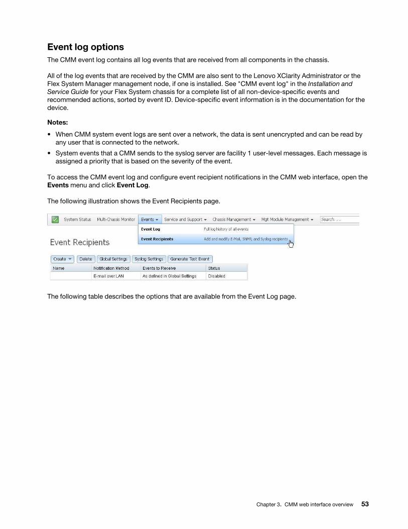
Event log optionsThe CMM event log contains all log events that are received from all components in the chassis.
All of the log events that are received by the CMM are also sent to the Lenovo XClarity Administrator or the Flex System Manager management node, if one is installed. See "CMM event log" in the Installation and Service Guide for your Flex System chassis for a complete list of all non-device-specific events and recommended actions, sorted by event ID. Device-specific event information is in the documentation for the device.
Notes:
• When CMM system event logs are sent over a network, the data is sent unencrypted and can be read by any user that is connected to the network.
• System events that a CMM sends to the syslog server are facility 1 user-level messages. Each message is assigned a priority that is based on the severity of the event.
To access the CMM event log and configure event recipient notifications in the CMM web interface, open the Events menu and click Event Log.
The following illustration shows the Event Recipients page.
The following table describes the options that are available from the Event Log page.
Chapter 3. CMM web interface overview 53
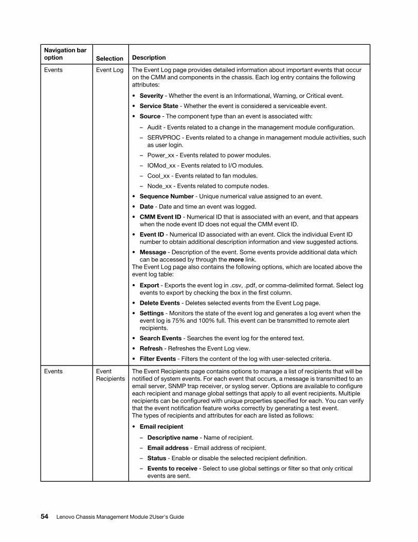
Navigation bar option Selection Description
Events Event Log The Event Log page provides detailed information about important events that occur on the CMM and components in the chassis. Each log entry contains the following attributes:
• Severity - Whether the event is an Informational, Warning, or Critical event.
• Service State - Whether the event is considered a serviceable event.
• Source - The component type than an event is associated with:
– Audit - Events related to a change in the management module configuration.
– SERVPROC - Events related to a change in management module activities, such as user login.
– Power_xx - Events related to power modules.
– IOMod_xx - Events related to I/O modules.
– Cool_xx - Events related to fan modules.
– Node_xx - Events related to compute nodes.
• Sequence Number - Unique numerical value assigned to an event.
• Date - Date and time an event was logged.
• CMM Event ID - Numerical ID that is associated with an event, and that appears when the node event ID does not equal the CMM event ID.
• Event ID - Numerical ID associated with an event. Click the individual Event ID number to obtain additional description information and view suggested actions.
• Message - Description of the event. Some events provide additional data which can be accessed by through the more link.
The Event Log page also contains the following options, which are located above the event log table:
• Export - Exports the event log in .csv, .pdf, or comma-delimited format. Select log events to export by checking the box in the first column.
• Delete Events - Deletes selected events from the Event Log page.
• Settings - Monitors the state of the event log and generates a log event when the event log is 75% and 100% full. This event can be transmitted to remote alert recipients.
• Search Events - Searches the event log for the entered text.
• Refresh - Refreshes the Event Log view.
• Filter Events - Filters the content of the log with user-selected criteria.
Events Event Recipients
The Event Recipients page contains options to manage a list of recipients that will be notified of system events. For each event that occurs, a message is transmitted to an email server, SNMP trap receiver, or syslog server. Options are available to configure each recipient and manage global settings that apply to all event recipients. Multiple recipients can be configured with unique properties specified for each. You can verify that the event notification feature works correctly by generating a test event. The types of recipients and attributes for each are listed as follows:
• Email recipient
– Descriptive name - Name of recipient.
– Email address - Email address of recipient.
– Status - Enable or disable the selected recipient definition.
– Events to receive - Select to use global settings or filter so that only critical events are sent.
54 Lenovo Chassis Management Module 2User's Guide
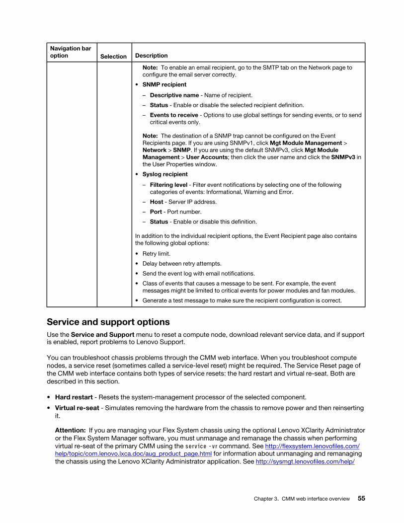
Navigation bar option Selection Description
Note: To enable an email recipient, go to the SMTP tab on the Network page to configure the email server correctly.
• SNMP recipient
– Descriptive name - Name of recipient.
– Status - Enable or disable the selected recipient definition.
– Events to receive - Options to use global settings for sending events, or to send critical events only.
Note: The destination of a SNMP trap cannot be configured on the Event Recipients page. If you are using SNMPv1, click Mgt Module Management > Network > SNMP. If you are using the default SNMPv3, click Mgt Module Management > User Accounts; then click the user name and click the SNMPv3 in the User Properties window.
• Syslog recipient
– Filtering level - Filter event notifications by selecting one of the following categories of events: Informational, Warning and Error.
– Host - Server IP address.
– Port - Port number.
– Status - Enable or disable this definition.
In addition to the individual recipient options, the Event Recipient page also contains the following global options:
• Retry limit.
• Delay between retry attempts.
• Send the event log with email notifications.
• Class of events that causes a message to be sent. For example, the event messages might be limited to critical events for power modules and fan modules.
• Generate a test message to make sure the recipient configuration is correct.
Service and support optionsUse the Service and Support menu to reset a compute node, download relevant service data, and if support is enabled, report problems to Lenovo Support.
You can troubleshoot chassis problems through the CMM web interface. When you troubleshoot compute nodes, a service reset (sometimes called a service-level reset) might be required. The Service Reset page of the CMM web interface contains both types of service resets: the hard restart and virtual re-seat. Both are described in this section.
• Hard restart - Resets the system-management processor of the selected component.
• Virtual re-seat - Simulates removing the hardware from the chassis to remove power and then reinserting it.
Attention: If you are managing your Flex System chassis using the optional Lenovo XClarity Administrator or the Flex System Manager software, you must unmanage and remanage the chassis when performing virtual re-seat of the primary CMM using the service -vr command. See http://flexsystem.lenovofiles.com/ help/topic/com.lenovo.lxca.doc/aug_product_page.html for information about unmanaging and remanaging the chassis using the Lenovo XClarity Administrator application. See http://sysmgt.lenovofiles.com/help/
Chapter 3. CMM web interface overview 55
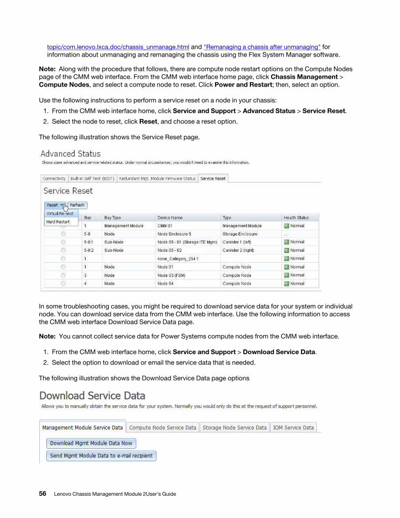
topic/com.lenovo.lxca.doc/chassis_unmanage.html and "Remanaging a chassis after unmanaging" for information about unmanaging and remanaging the chassis using the Flex System Manager software.
Note: Along with the procedure that follows, there are compute node restart options on the Compute Nodes page of the CMM web interface. From the CMM web interface home page, click Chassis Management > Compute Nodes, and select a compute node to reset. Click Power and Restart; then, select an option.
Use the following instructions to perform a service reset on a node in your chassis:
1. From the CMM web interface home, click Service and Support > Advanced Status > Service Reset.
2. Select the node to reset, click Reset, and choose a reset option.
The following illustration shows the Service Reset page.
In some troubleshooting cases, you might be required to download service data for your system or individual node. You can download service data from the CMM web interface. Use the following information to access the CMM web interface Download Service Data page.
Note: You cannot collect service data for Power Systems compute nodes from the CMM web interface.
1. From the CMM web interface home, click Service and Support > Download Service Data.
2. Select the option to download or email the service data that is needed.
The following illustration shows the Download Service Data page options
56 Lenovo Chassis Management Module 2User's Guide
When support is needed, you can contact Lenovo Support or your approved service provider by using the Service Advisor software. Service Advisor is on the CMM and monitors the chassis hardware events. When Service Advisor detects a hardware event, it can be reported to Lenovo Support, or depending upon your service agreement, an approved service provider. For each automatic support notification Lenovo receives, a service ticket will be opened, and a follow-up call will be made. For you to use Service Advisor, it must be enabled and configured to send an automatic support notification to Lenovo support.
Complete the following steps to enable Service Advisor:
1. From the CMM web interface home, click Service and Support > Settings.
2. On the Support page, select the Enable Support check box, enter the applicable information, and click Apply at the bottom of the page.
The following illustration shows the Service and Support > Settings page.
Chapter 3. CMM web interface overview 57
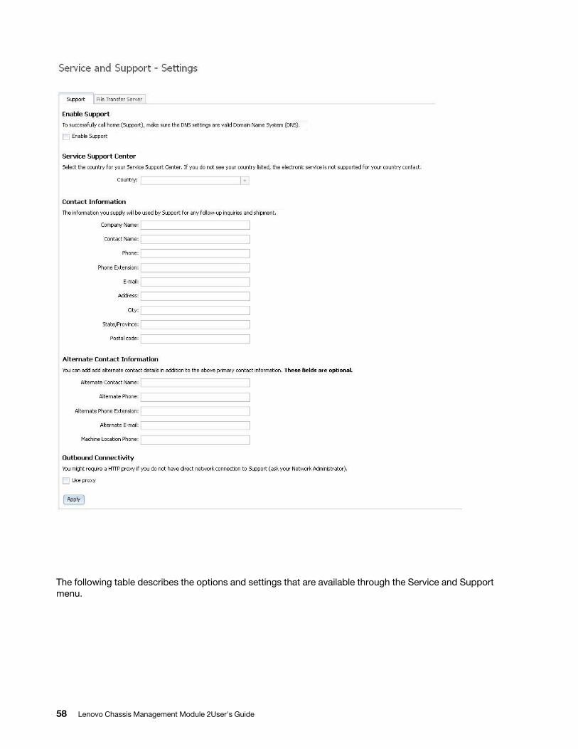
The following table describes the options and settings that are available through the Service and Support menu.
58 Lenovo Chassis Management Module 2User's Guide
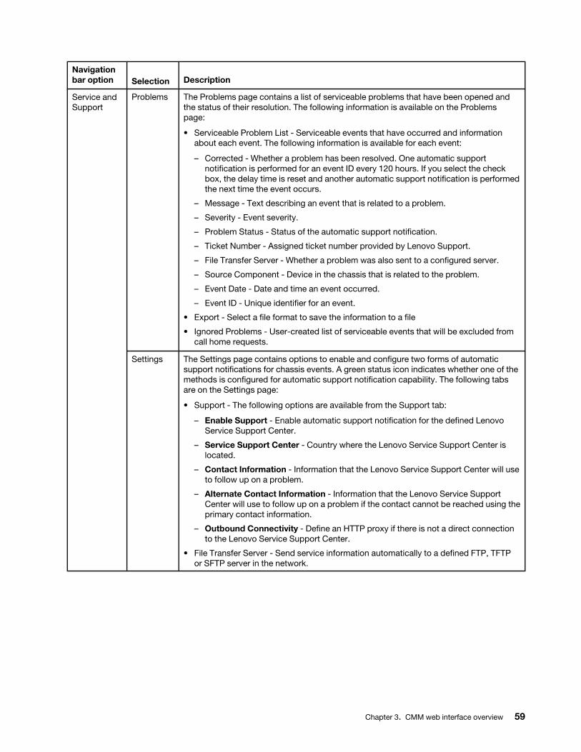
Navigation bar option Selection Description
Service and Support
Problems The Problems page contains a list of serviceable problems that have been opened and the status of their resolution. The following information is available on the Problems page:
• Serviceable Problem List - Serviceable events that have occurred and information about each event. The following information is available for each event:
– Corrected - Whether a problem has been resolved. One automatic support notification is performed for an event ID every 120 hours. If you select the check box, the delay time is reset and another automatic support notification is performed the next time the event occurs.
– Message - Text describing an event that is related to a problem.
– Severity - Event severity.
– Problem Status - Status of the automatic support notification.
– Ticket Number - Assigned ticket number provided by Lenovo Support.
– File Transfer Server - Whether a problem was also sent to a configured server.
– Source Component - Device in the chassis that is related to the problem.
– Event Date - Date and time an event occurred.
– Event ID - Unique identifier for an event.
• Export - Select a file format to save the information to a file
• Ignored Problems - User-created list of serviceable events that will be excluded from call home requests.
Settings The Settings page contains options to enable and configure two forms of automatic support notifications for chassis events. A green status icon indicates whether one of the methods is configured for automatic support notification capability. The following tabs are on the Settings page:
• Support - The following options are available from the Support tab:
– Enable Support - Enable automatic support notification for the defined Lenovo Service Support Center.
– Service Support Center - Country where the Lenovo Service Support Center is located.
– Contact Information - Information that the Lenovo Service Support Center will use to follow up on a problem.
– Alternate Contact Information - Information that the Lenovo Service Support Center will use to follow up on a problem if the contact cannot be reached using the primary contact information.
– Outbound Connectivity - Define an HTTP proxy if there is not a direct connection to the Lenovo Service Support Center.
• File Transfer Server - Send service information automatically to a defined FTP, TFTP or SFTP server in the network.
Chapter 3. CMM web interface overview 59
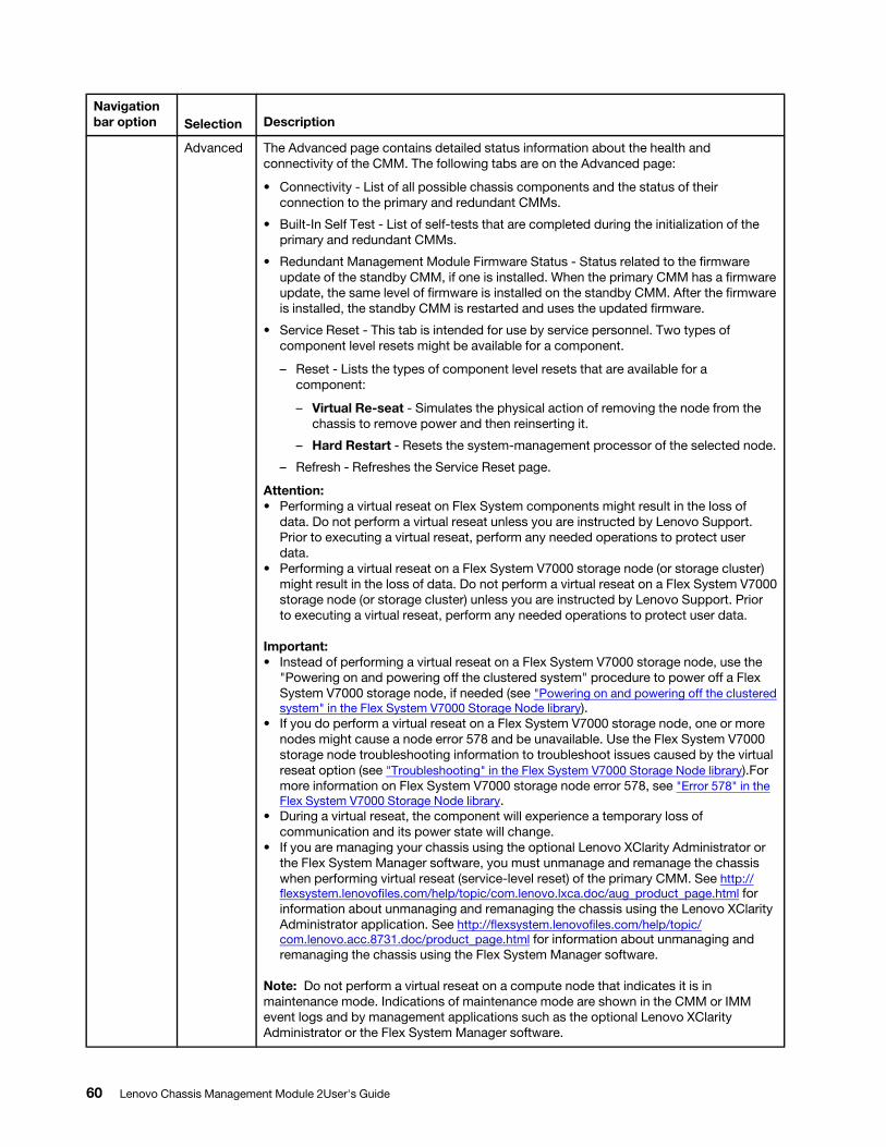
Navigation bar option Selection Description
Advanced The Advanced page contains detailed status information about the health and connectivity of the CMM. The following tabs are on the Advanced page:
• Connectivity - List of all possible chassis components and the status of their connection to the primary and redundant CMMs.
• Built-In Self Test - List of self-tests that are completed during the initialization of the primary and redundant CMMs.
• Redundant Management Module Firmware Status - Status related to the firmware update of the standby CMM, if one is installed. When the primary CMM has a firmware update, the same level of firmware is installed on the standby CMM. After the firmware is installed, the standby CMM is restarted and uses the updated firmware.
• Service Reset - This tab is intended for use by service personnel. Two types of component level resets might be available for a component.
– Reset - Lists the types of component level resets that are available for a component:
– Virtual Re-seat - Simulates the physical action of removing the node from the chassis to remove power and then reinserting it.
– Hard Restart - Resets the system-management processor of the selected node.
– Refresh - Refreshes the Service Reset page.
Attention: • Performing a virtual reseat on Flex System components might result in the loss of
data. Do not perform a virtual reseat unless you are instructed by Lenovo Support. Prior to executing a virtual reseat, perform any needed operations to protect user data.
• Performing a virtual reseat on a Flex System V7000 storage node (or storage cluster) might result in the loss of data. Do not perform a virtual reseat on a Flex System V7000 storage node (or storage cluster) unless you are instructed by Lenovo Support. Prior to executing a virtual reseat, perform any needed operations to protect user data.
Important: • Instead of performing a virtual reseat on a Flex System V7000 storage node, use the
"Powering on and powering off the clustered system" procedure to power off a Flex System V7000 storage node, if needed (see "Powering on and powering off the clustered system" in the Flex System V7000 Storage Node library).
• If you do perform a virtual reseat on a Flex System V7000 storage node, one or more nodes might cause a node error 578 and be unavailable. Use the Flex System V7000 storage node troubleshooting information to troubleshoot issues caused by the virtual reseat option (see "Troubleshooting" in the Flex System V7000 Storage Node library).For more information on Flex System V7000 storage node error 578, see "Error 578" in the Flex System V7000 Storage Node library.
• During a virtual reseat, the component will experience a temporary loss of communication and its power state will change.
• If you are managing your chassis using the optional Lenovo XClarity Administrator or the Flex System Manager software, you must unmanage and remanage the chassis when performing virtual reseat (service-level reset) of the primary CMM. See http:// flexsystem.lenovofiles.com/help/topic/com.lenovo.lxca.doc/aug_product_page.html for information about unmanaging and remanaging the chassis using the Lenovo XClarity Administrator application. See http://flexsystem.lenovofiles.com/help/topic/ com.lenovo.acc.8731.doc/product_page.html for information about unmanaging and remanaging the chassis using the Flex System Manager software.
Note: Do not perform a virtual reseat on a compute node that indicates it is in maintenance mode. Indications of maintenance mode are shown in the CMM or IMM event logs and by management applications such as the optional Lenovo XClarity Administrator or the Flex System Manager software.
60 Lenovo Chassis Management Module 2User's Guide
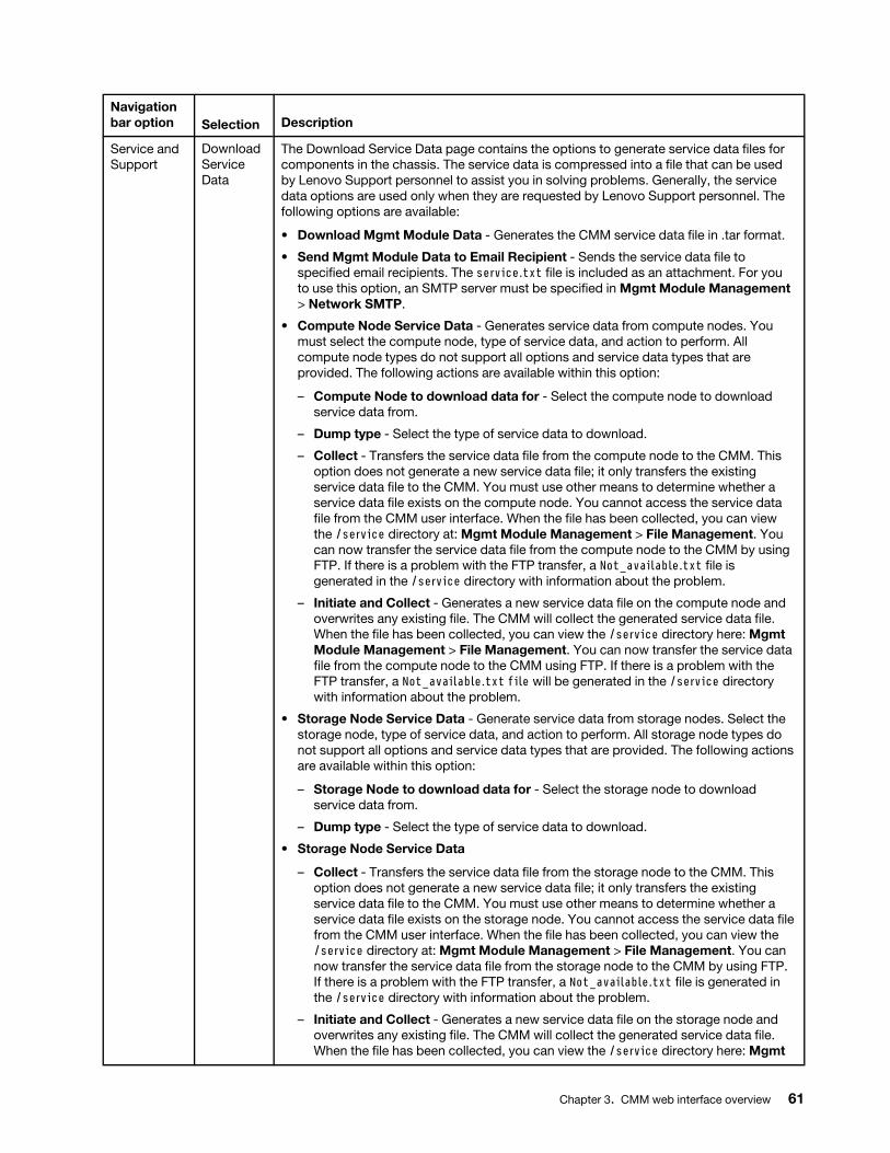
Navigation bar option Selection Description
Service and Support
Download Service Data
The Download Service Data page contains the options to generate service data files for components in the chassis. The service data is compressed into a file that can be used by Lenovo Support personnel to assist you in solving problems. Generally, the service data options are used only when they are requested by Lenovo Support personnel. The following options are available:
• Download Mgmt Module Data - Generates the CMM service data file in .tar format.
• Send Mgmt Module Data to Email Recipient - Sends the service data file to specified email recipients. The service.txt file is included as an attachment. For you to use this option, an SMTP server must be specified in Mgmt Module Management > Network SMTP.
• Compute Node Service Data - Generates service data from compute nodes. You must select the compute node, type of service data, and action to perform. All compute node types do not support all options and service data types that are provided. The following actions are available within this option:
– Compute Node to download data for - Select the compute node to download service data from.
– Dump type - Select the type of service data to download.
– Collect - Transfers the service data file from the compute node to the CMM. This option does not generate a new service data file; it only transfers the existing service data file to the CMM. You must use other means to determine whether a service data file exists on the compute node. You cannot access the service data file from the CMM user interface. When the file has been collected, you can view the /service directory at: Mgmt Module Management > File Management. You can now transfer the service data file from the compute node to the CMM by using FTP. If there is a problem with the FTP transfer, a Not_available.txt file is generated in the /service directory with information about the problem.
– Initiate and Collect - Generates a new service data file on the compute node and overwrites any existing file. The CMM will collect the generated service data file. When the file has been collected, you can view the /service directory here: Mgmt Module Management > File Management. You can now transfer the service data file from the compute node to the CMM using FTP. If there is a problem with the FTP transfer, a Not_available.txt file will be generated in the /service directory with information about the problem.
• Storage Node Service Data - Generate service data from storage nodes. Select the storage node, type of service data, and action to perform. All storage node types do not support all options and service data types that are provided. The following actions are available within this option:
– Storage Node to download data for - Select the storage node to download service data from.
– Dump type - Select the type of service data to download.
• Storage Node Service Data
– Collect - Transfers the service data file from the storage node to the CMM. This option does not generate a new service data file; it only transfers the existing service data file to the CMM. You must use other means to determine whether a service data file exists on the storage node. You cannot access the service data file from the CMM user interface. When the file has been collected, you can view the /service directory at: Mgmt Module Management > File Management. You can now transfer the service data file from the storage node to the CMM by using FTP. If there is a problem with the FTP transfer, a Not_available.txt file is generated in the /service directory with information about the problem.
– Initiate and Collect - Generates a new service data file on the storage node and overwrites any existing file. The CMM will collect the generated service data file. When the file has been collected, you can view the /service directory here: Mgmt
Chapter 3. CMM web interface overview 61
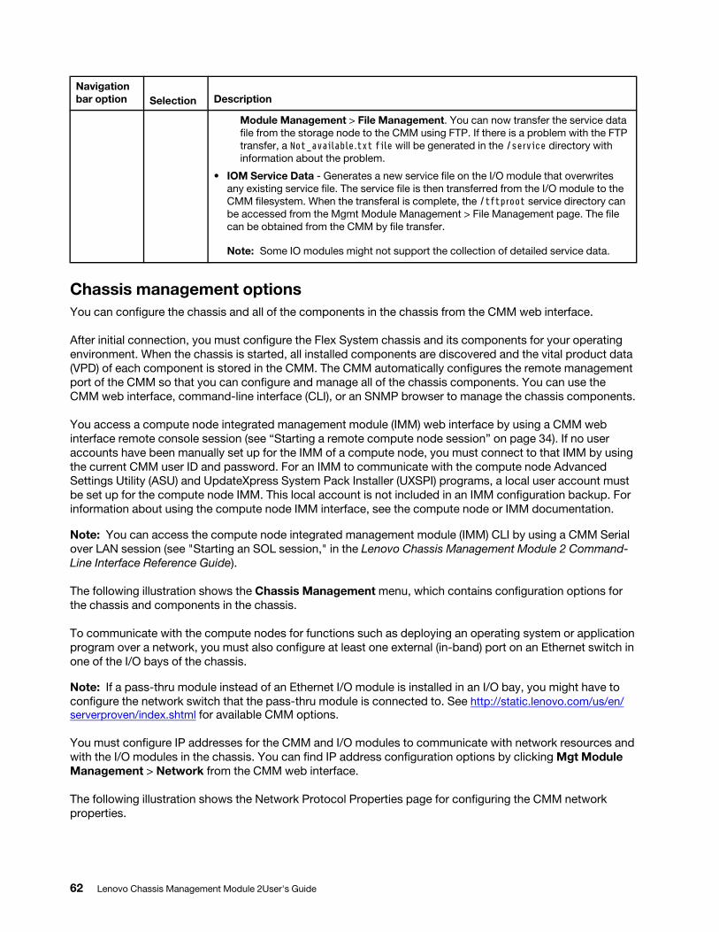
Navigation bar option Selection Description
Module Management > File Management. You can now transfer the service data file from the storage node to the CMM using FTP. If there is a problem with the FTP transfer, a Not_available.txt file will be generated in the /service directory with information about the problem.
• IOM Service Data - Generates a new service file on the I/O module that overwrites any existing service file. The service file is then transferred from the I/O module to the CMM filesystem. When the transferal is complete, the /tftproot service directory can be accessed from the Mgmt Module Management > File Management page. The file can be obtained from the CMM by file transfer.
Note: Some IO modules might not support the collection of detailed service data.
Chassis management optionsYou can configure the chassis and all of the components in the chassis from the CMM web interface.
After initial connection, you must configure the Flex System chassis and its components for your operating environment. When the chassis is started, all installed components are discovered and the vital product data (VPD) of each component is stored in the CMM. The CMM automatically configures the remote management port of the CMM so that you can configure and manage all of the chassis components. You can use the CMM web interface, command-line interface (CLI), or an SNMP browser to manage the chassis components.
You access a compute node integrated management module (IMM) web interface by using a CMM web interface remote console session (see “Starting a remote compute node session” on page 34). If no user accounts have been manually set up for the IMM of a compute node, you must connect to that IMM by using the current CMM user ID and password. For an IMM to communicate with the compute node Advanced Settings Utility (ASU) and UpdateXpress System Pack Installer (UXSPI) programs, a local user account must be set up for the compute node IMM. This local account is not included in an IMM configuration backup. For information about using the compute node IMM interface, see the compute node or IMM documentation.
Note: You can access the compute node integrated management module (IMM) CLI by using a CMM Serial over LAN session (see "Starting an SOL session," in the Lenovo Chassis Management Module 2 Command- Line Interface Reference Guide).
The following illustration shows the Chassis Management menu, which contains configuration options for the chassis and components in the chassis.
To communicate with the compute nodes for functions such as deploying an operating system or application program over a network, you must also configure at least one external (in-band) port on an Ethernet switch in one of the I/O bays of the chassis.
Note: If a pass-thru module instead of an Ethernet I/O module is installed in an I/O bay, you might have to configure the network switch that the pass-thru module is connected to. See http://static.lenovo.com/us/en/ serverproven/index.shtml for available CMM options.
You must configure IP addresses for the CMM and I/O modules to communicate with network resources and with the I/O modules in the chassis. You can find IP address configuration options by clicking Mgt Module Management > Network from the CMM web interface.
The following illustration shows the Network Protocol Properties page for configuring the CMM network properties.
62 Lenovo Chassis Management Module 2User's Guide
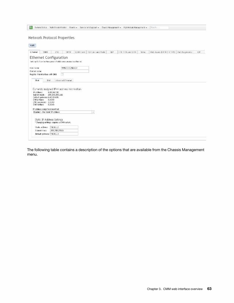
The following table contains a description of the options that are available from the Chassis Management menu.
Chapter 3. CMM web interface overview 63
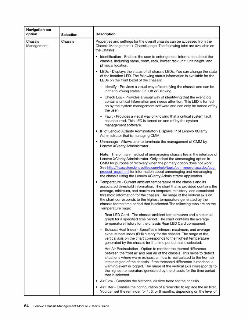
Navigation bar option Selection Description
Chassis Management
Chassis Properties and settings for the overall chassis can be accessed from the Chassis Management > Chassis page. The following tabs are available on the Chassis:
• Identification - Enables the user to enter general information about the chassis, including name, room, rack, lowest rack unit, unit height, and physical location.
• LEDs - Displays the status of all chassis LEDs. You can change the state of the location LED. The following status information is available for the LEDs on the front bezel of the chassis:
– Identify - Provides a visual way of identifying the chassis and can be in the following states: On, Off or Blinking.
– Check Log - Provides a visual way of identifying that the event log contains critical information and needs attention. This LED is turned on by the system management software and can only be turned off by the user.
– Fault - Provides a visual way of knowing that a critical system fault has occurred. This LED is turned on and off by the system management software.
• IP of Lenovo XClarity Administrator- Displays IP of Lenovo XClarity Administrator that is managing CMM.
• Unmanage - Allows user to terminate the management of CMM by Lenovo XClarity Administrator.
Note: The primary method of unmanaging chassis lies in the interface of Lenovo XClarity Administrator. Only adopt the unmanaging option in CMM for purpose of recovery when the primary option does not work. See http://flexsystem.lenovofiles.com/help/topic/com.lenovo.lxca.doc/aug_ product_page.html for information about unmanaging and remanaging the chassis using the Lenovo XClarity Administrator application.
• Temperature - Current ambient temperature of the chassis and its associated threshold information. The chart that is provided contains the average, minimum, and maximum temperature history, and associated threshold information for the chassis. The range of the vertical axis on the chart corresponds to the highest temperature generated by the chassis for the time period that is selected.The following tabs are on the Temperature page:
– Rear LED Card - The chassis ambient temperatures and a historical graph for a specified time period. The chart contains the average temperature history for the chassis Rear LED Card component.
– Exhaust Heat Index - Specifies minimum, maximum, and average exhaust heat index (EHI) history for the chassis. The range of the vertical axis on the chart corresponds to the highest temperature generated by the chassis for the time period that is selected.
– Hot Air Recirculation - Option to monitor the thermal difference between the front air and rear air of the chassis. This helps to detect situations where warm exhaust air flow is recirculated to the front air intake region of the chassis. If the threshold difference is reached, a warning event is logged. The range of the vertical axis corresponds to the highest temperature generated by the chassis for the time period that is selected.
• Air Flow - Contains the historical air flow trend for the chassis.
• Air Filter - Enables the configuration of a reminder to replace the air filter. You can set the reminder for 1, 3, or 6 months, depending on the level of
64 Lenovo Chassis Management Module 2User's Guide
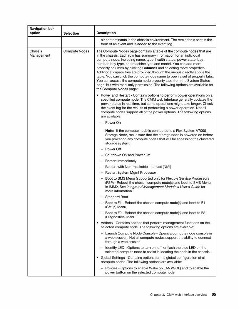
Navigation bar option Selection Description
air contaminants in the chassis environment. The reminder is sent in the form of an event and is added to the event log.
Chassis Management
Compute Nodes The Compute Nodes page contains a table of the compute nodes that are in the chassis. Each row has summary information for an individual compute node, including name, type, health status, power state, bay number, bay type, and machine type and model. You can add more property columns by clicking Columns and selecting more properties. Additional capabilities are provided through the menus directly above the table. You can click the compute node name to open a set of property tabs. You can access the compute node property tabs from the System Status page, but with read-only permission. The following options are available on the Compute Nodes page:
• Power and Restart - Contains options to perform power operations on a specified compute node. The CMM web interface generally updates the power status in real time, but some operations might take longer. Check the event log for the results of performing a power operation. Not all compute nodes support all of the power options. The following options are available:
– Power On
Note: If the compute node is connected to a Flex System V7000 Storage Node, make sure that the storage node is powered on before you power on any compute nodes that will be accessing the clustered storage system.
– Power Off
– Shutdown OS and Power Off
– Restart Immediately
– Restart with Non-maskable Interrupt (NMI)
– Restart System Mgmt Processor
– Boot to SMS Menu (supported only for Flexible Service Processors (FSP))- Reboot the chosen compute node(s) and boot to SMS Menu in IMM2. See Integrated Management Module II User's Guide for more information.
– Standard Boot
– Boot to F1 - Reboot the chosen compute node(s) and boot to F1 (Setup) Menu.
– Boot to F2 - Reboot the chosen compute node(s) and boot to F2 (Diagnostics) Menu.
• Actions - Contains options that perform management functions on the selected compute node. The following options are available:
– Launch Compute Node Console - Opens a compute node console in a web session. Not all compute nodes support the ability to connect through a web session.
– Identify LED - Options to turn on, off, or flash the blue LED on the selected compute node to assist in locating the node in the chassis.
• Global Settings - Contains options for the global configuration of all compute nodes. The following options are available:
– Policies - Options to enable Wake on LAN (WOL) and to enable the power button on the selected compute node.
Chapter 3. CMM web interface overview 65
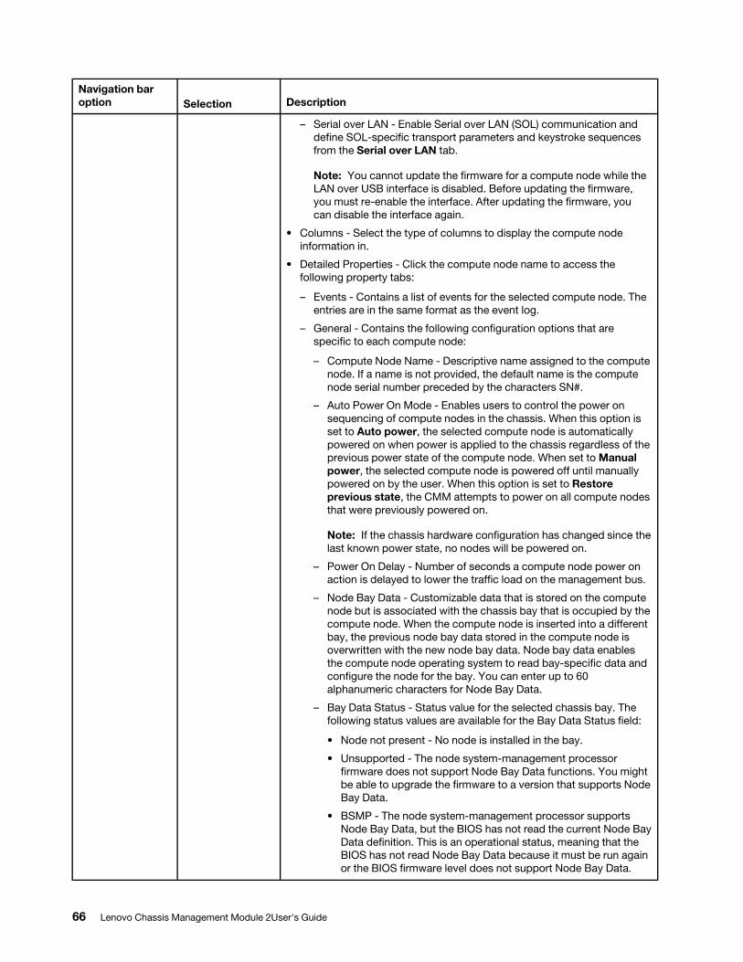
Navigation bar option Selection Description
– Serial over LAN - Enable Serial over LAN (SOL) communication and define SOL-specific transport parameters and keystroke sequences from the Serial over LAN tab.
Note: You cannot update the firmware for a compute node while the LAN over USB interface is disabled. Before updating the firmware, you must re-enable the interface. After updating the firmware, you can disable the interface again.
• Columns - Select the type of columns to display the compute node information in.
• Detailed Properties - Click the compute node name to access the following property tabs:
– Events - Contains a list of events for the selected compute node. The entries are in the same format as the event log.
– General - Contains the following configuration options that are specific to each compute node:
– Compute Node Name - Descriptive name assigned to the compute node. If a name is not provided, the default name is the compute node serial number preceded by the characters SN#.
– Auto Power On Mode - Enables users to control the power on sequencing of compute nodes in the chassis. When this option is set to Auto power, the selected compute node is automatically powered on when power is applied to the chassis regardless of the previous power state of the compute node. When set to Manual power, the selected compute node is powered off until manually powered on by the user. When this option is set to Restore previous state, the CMM attempts to power on all compute nodes that were previously powered on.
Note: If the chassis hardware configuration has changed since the last known power state, no nodes will be powered on.
– Power On Delay - Number of seconds a compute node power on action is delayed to lower the traffic load on the management bus.
– Node Bay Data - Customizable data that is stored on the compute node but is associated with the chassis bay that is occupied by the compute node. When the compute node is inserted into a different bay, the previous node bay data stored in the compute node is overwritten with the new node bay data. Node bay data enables the compute node operating system to read bay-specific data and configure the node for the bay. You can enter up to 60 alphanumeric characters for Node Bay Data.
– Bay Data Status - Status value for the selected chassis bay. The following status values are available for the Bay Data Status field:
• Node not present - No node is installed in the bay.
• Unsupported - The node system-management processor firmware does not support Node Bay Data functions. You might be able to upgrade the firmware to a version that supports Node Bay Data.
• BSMP - The node system-management processor supports Node Bay Data, but the BIOS has not read the current Node Bay Data definition. This is an operational status, meaning that the BIOS has not read Node Bay Data because it must be run again or the BIOS firmware level does not support Node Bay Data.
66 Lenovo Chassis Management Module 2User's Guide
Navigation bar option Selection Description
• Supported - The node fully supports Node Bay Data. The latest Node Bay Data definition is in the system-management processor and BIOS SMBIOS structure.
• Discovering - Usually displayed for a short time while the node is being discovered by the CMM.
– Management Network Status - Internal management network interface status for the selected compute node.
– Internal Mgmt Port MAC - Internal management network interface MAC address for the selected compute node.
– Powered On Time - Elapsed time since the selected compute node has been powered on.
– Number of OS Boots - Number of times the node has booted from the operating system since the most recent insertion into the chassis.
– Enable Wake-On LAN - Individual node setting for Wake on LAN (WOL) support.
– Enable Serial Over LAN - Individual node setting for Serial over LAN (SOL) support.
– Enable Local Power Control - Individual node setting for the power button on the node.
– Enable Ethernet Over USB - Individual node setting for the internal Ethernet interface over USB. This field is not supported by all nodes and is not visible when it is not supported.
Note: You cannot update the firmware for a compute node while the Enable Ethernet Over USB option is disabled. Before updating the firmware, you must enable the option. After updating the firmware, you can disable the option again.
– Hardware - Contains a hierarchical file tree on the left portion of the screen and associated inventory data for the selected component. A parent component (one with a +/- box) can be expanded to show its associated child components. Click the parent component to view some basic information about the parent component and a table of its associated child components. The columns in the table provide full inventory data of the associated child components. When the lowest level child component is reached (one without a +/- box), click the node to view full inventory data of the child component.
– Firmware - Identification information for the component firmware, including installed network adapters. Some components might have multiple firmware loads; in this case, the multiple firmware releases are contained in a table.
– Power - Contains the following power statistics for the selected component:
– Power State - Indicates whether the component is powered on or off.
– Power In Use - Current power consumption of the component.
– Minimum/Maximum Allocation - Minimum and maximum power allocated to the component.
– Capabilities - Power management capabilities that are supported by the component.
Chapter 3. CMM web interface overview 67
Navigation bar option Selection Description
– Power Saving Options - List of power saving policy settings. The following settings are available:
• No power savings - Indicates that there is no power saving policy set.
• Static low power saver - Reduces power consumption by altering the operating voltage and frequency.
• Dynamic power saver - Controls the operating voltage and frequency of the microprocessors, based on the load.
– Power Capping Options - Enables a power limit to control the maximum power that is consumed by the component.
– Consumption History - Graphical representation of power consumption over a set amount of time.
– Environmentals - Provides information about the selected compute node, including:
– Temperature History - Graph of temperature records of the selected compute/storage node for up to the past 24 hours. The data is recorded every 10 minutes since CMM is running and the selected node is active. Display options include 1, 6, 12, and 24 hours, while scale of vertical axis in the graph is defined by the highest value recorded.
Note: Stored data would be cleansed with CMM reset. For the next data entry after reset, the user has to wait for a whole interval of 10 minutes after CMM is up and running and the selected node is active.
– Processor History - Graph of CPU usage percentages of the selected compute node for up to the past 24 hours. The data is recorded every 10 minutes since CMM is running and the chosen compute node is active with power on. Display options include 1, 6, 12, and 24 hours, while scale of vertical axis in the graph is defined by the highest value recorded.
Notes:
1. The data is not available for storage node.
2. Stored data would be cleansed with CMM reset. For the next data entry after reset, the user has to wait for a whole interval of 10 minutes after CMM is up and running and the chosen compute node is active with power on.
– Memory History - Graph of memory usage percentages of the selected compute node for up to the past 24 hours. The data is recorded every 10 minutes since CMM is running and the chosen node is active with power on and operating system running. Display options include 1, 6, 12, and 24 hours, while scale of vertical axis in the graph is defined by the highest value recorded.
Notes:
• The data is only available for Lenovo Flex System x240 M5 Compute Node Type 9532. See http://flexsystem.lenovofiles.com/ help/topic/com.lenovo.acc.9532.doc/product_page.html for more information.
• Stored data would be cleansed with CMM reset. For the next data entry after reset, the user has to wait for a whole interval of
68 Lenovo Chassis Management Module 2User's Guide
Navigation bar option Selection Description
10 minutes after CMM is up and running and the selected compute node is active.
– Status - Other information of the selected component, such as voltage. Some components might also provide one or more threshold values.
– IO Connectivity - Displays connectivity status and compatibility details for the selected node and the I/O modules that it is connected to.
– SOL Status - Contains information about Serial Over LAN connection and configuration for the selected node.
– Boot Sequence - Contains options that enable the user to select the order of boot devices for the node when it is powered on. The options apply to compute nodes. Possible devices are displayed in the order in which they will be powered on. The following attributes are available for each device:
– Device ID - Numeric identifier of the device.
– Active - Whether the device can be used in the boot order.
– Presence - Whether the device is present. A missing device can be added to the boot sequence. When the device is present, it will be powered on.
– Device Label - Identification label provided by the device itself.
– User Label - Identification label specified by the user.
– Order - Location of the device in the boot order.
– LEDs - Displays LEDs that are present on the device, including title, description, and state. All information viewed from the CMM graphical view property tabs is read-only. You can access options to change the state of some LEDs by clicking: Chassis Management > Compute Nodes > Actions.
– Boot Mode - Contains boot options to indicate the location of the active and pending compute node firmware. This tab applies only to compute nodes and has the following options:
– Active boot mode - Location of the active copy of the compute node firmware, either the temporary bank or the permanent bank.
– Pending boot mode - Location that the compute node firmware will be obtained from on the next reboot, either the temporary bank or the permanent bank.
Chassis Management
Storage Nodes The Storage Nodes page contains a table of the storage nodes that are in the chassis. Each row has summary information for the individual storage nodes, including device name, device type, health status, power state, bay number, bay type, and machine type and model. You can add more property columns by clicking Columns and selecting more properties. Additional capabilities are provided through the menus directly above the table. You can click the storage node name to open a set of property tabs. You can access the storage node property tabs from the System Status page, but with read-only permission. The storage node name can be clicked to open the following tabs:
• Power and Restart - Contains options to perform power operations on a specified compute node. The CMM web interface generally updates the power status in real time, but some operations might take longer. Check the event log for the results of performing a power operation. Not all
Chapter 3. CMM web interface overview 69
Navigation bar option Selection Description
compute nodes support all of the power options. The following options are available:
– Power On
– Power Off (SRC will shutdown the OS)
– Restart System Management Processor
• Actions - Contains the following options that perform management functions on the selected compute node:
– Launch Storage Node Console - Opens a storage node console in a web session. Not all storage nodes support the ability to connect through a web session.
– Identify LED - Options to turn on, off, or flash the blue LED on the selected compute node to assist in locating the node in the chassis.
• Detailed Properties - Click the compute node name to access the property tabs. The following list includes all of the detailed properties, but not every property applies to every component:
– Events - Contains a list of events for the selected node. The entries are in the same format as the event log.
– General - Contains the following configuration options that are specific to each storage node:
– Node Name - Descriptive name assigned to the compute node. If a name is not provided, the default name will be the compute node serial number preceded by the characters SN#.
– Auto Power On Mode - Storage nodes are automatically powered on. This setting can not be configured for storage nodes.
– Power On Delay - Number of seconds a compute node power on action is delayed. This gives the user control to power on the nodes process of compute nodes in order to lower the traffic load on the management bus.
– Node Bay Data - Customizable data that is stored on the node, but is associated with the chassis bay that is occupied by the node. When the node is inserted into a different bay, the previous node bay data stored in the node is overwritten with the new node bay data. Node bay data enables the node OS to read bay-specific data and configure the node for the bay. You can enter up to 60 alphanumeric characters for Node Bay Data.
– Bay Data Status - Storage nodes do not support bay data status reporting.
– Hardware - Contains a hierarchical file tree on the left portion of the screen and associated inventory data for the selected component. A parent component (one with a +/- box) can be expanded to show its associated child component. Click the parent component to view some basic information about the parent component and a table of its associated child components. The columns in the table provide full inventory data of the associated child components. When the lowest level child component is reached (one without a +/- box), click the node to view full inventory data of the child component.
– Firmware - Contains identification information for the firmware of the selected component, including installed network adapter cards. If the selected component has multiple firmware loads, they will be contained in a table.
70 Lenovo Chassis Management Module 2User's Guide
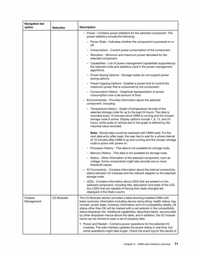
Navigation bar option Selection Description
– Power - Contains power statistics for the selected component. The power statistics include the following:
– Power State - Indicates whether the component is powered on or off.
– Consumption - Current power consumption of the component.
– Allocation - Minimum and maximum power allocated for the selected component.
– Capabilities - List of power management capabilities supported by the selected node and statistics used in the power management algorithms.
– Power Saving Options - Storage nodes do not support power saving options.
– Power Capping Options - Enables a power limit to control the maximum power that is consumed by the component.
– Consumption History - Graphical representation of power consumption over a set amount of time.
– Environmentals - Provides information about the selected component, including:
– Temperature History - Graph of temperature records of the selected storage node for up to the past 24 hours. The data is recorded every 10 minutes since CMM is running and the chosen storage node is active. Display options include 1, 6, 12, and 24 hours, while scale of vertical axis in the graph is defined by the maximal value recorded.
Note: Stored data would be cleansed with CMM reset. For the next data entry after reset, the user has to wait for a whole interval of 10 minutes after CMM is up and running and the chosen storage node is active with power on.
– Processor History - This data is not available for storage node.
– Memory History - This data is not available for storage node.
– Status - Other information of the selected component, such as voltage. Some components might also provide one or more threshold values.
– IO Connectivity - Contains information about the internal connectivity status between I/O modules and the network adapter on the selected storage node.
– LEDs - Contains information about LEDs that are present on the selected component, including title, description and state of the LED. Any LEDs that are capable of having their state changed are displayed in the State column.
Chassis Management
I/O Modules The I/O Modules section provides a table showing installed IOMs with basic summary information including device name string, health status, bay number, power state, inventory information and I/O compatibility details. All status other than OK will be marked with a red asterisk in the compatibility status dropdown list. Additional capabilities, described below, are provided by other dropdown menus above the table, and in addition, the I/O module name can be clicked to open a set of property tabs.
• Power and Restart - Contains power operations for the selected I/O modules. The web interface updates the power status in real time, but some operations might take longer. Check the event log for the results of
Chapter 3. CMM web interface overview 71

Navigation bar option Selection Description
a power operation. The following power options are available are from the Power and Restart menu:
– Power On
– Power Off
– Restart Immediately and Run Standard Diagnostics
– Restart Immediately and Run Full Diagnostics
– Restart Immediately and Run Extended Diagnostics
• Actions - Contains the following menu options for the selected module:
– Reset Factory Defaults - Sets the configuration to the factory defaults
– Send Ping Requests - Sends a diagnostic stream of pings to the module
– Launch IOM Console - Launches a web session to directly access the module
– Identify LED - Manages the identification LED
• Detailed Properties - Click the I/O module name to access its detailed properties. The following list includes all of the detailed properties, but not every property applies to every component:
– Events - Contains a list of events that are relevant to the selected component. The entries are in the same format as the full event log.
– General - Contains the following configuration options that are specific to each I/O module:
– Stacking Mode - The current stacking mode state of the I/O module:
• N/A - The I/O module does not have stacking capability.
• Standby - The I/O module has stacking capability but is not part of a stack at the moment.
• Master - The I/O module has stacking capability and is part of a stack right now in the master role.
• Member - The I/O module has stacking capability and is part of a stack right now in the member role.
– Post Status - The results of an I/O module power-on self-test during switch initialization.
– Protected Mode Status - The current protected mode state of the I/ O module:
• N/A - Protected mode capability does not exist on the I/O module.
• Disabled - Protected mode capability exists on the I/O module, but has not been enabled.
• Pending - Protected mode has been activated on the CMM, but is still being activated for the I/O module.
• Active - Protected mode is active on the I/O module and the CMM.
• Attention - Protected mode is enabled on the I/O module, but not on the CMM.
– Management Network Status - The internal management network interface status for this I/O module. This field might not be available for I/O modules that are members of a stack.
72 Lenovo Chassis Management Module 2User's Guide
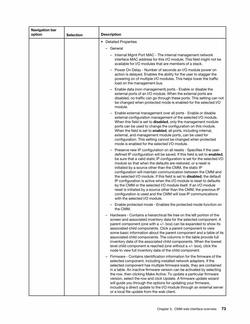
Navigation bar option Selection Description
• Detailed Properties
– General
– Internal Mgmt Port MAC - The internal management network interface MAC address for this I/O module. This field might not be available for I/O modules that are members of a stack.
– Power On Delay - Number of seconds an I/O module power on action is delayed. Enables the ability for the user to stagger the powering on of multiple I/O modules. This helps lower the traffic load on the management bus.
– Enable data (non-management) ports - Enable or disable the external ports of an I/O module. When the external ports are disabled, no traffic can go through these ports. This setting can not be changed when protected mode is enabled for the selected I/O module.
– Enable external management over all ports - Enable or disable external configuration management of the selected I/O module. When this field is set to disabled, only the management module ports can be used to change the configuration on this module. When the field is set to enabled, all ports, including internal, external, and management module ports, can be used for configuration. This setting cannot be changed when protected mode is enabled for the selected I/O module.
– Preserve new IP configuration on all resets - Specifies if the user- defined IP configuration will be saved. If this field is set to enabled, be sure that a valid static IP configuration is set for the selected I/O module so that when the defaults are restored, or a reset is initiated by a source other than the CMM, the static IP configuration will maintain communication between the CMM and the selected I/O module. If this field is set to disabled, the default IP configuration is active when the I/O module is reset to defaults by the CMM or the selected I/O module itself. If an I/O module reset is initiated by a source other than the CMM, the previous IP configuration is used and the CMM will lose IP communications with the selected I/O module.
– Enable protected mode - Enables the protected mode function on the CMM.
– Hardware - Contains a hierarchical file tree on the left portion of the screen and associated inventory data for the selected component. A parent component (one with a +/- box) can be expanded to show its associated child components. Click a parent component to view some basic information about the parent component and a table of its associated child components. The columns in the table provide full inventory data of the associated child components. When the lowest level child component is reached (one without a +/- box), click the node to view full inventory data of the child component.
– Firmware - Contains identification information for the firmware of the selected component, including installed network adapters. If the selected component has multiple firmware loads, they are contained in a table. An inactive firmware version can be activated by selecting the row, then clicking Make Active. To update a particular firmware version, select the row and click Update. A firmware update wizard will guide you through the options for updating your firmware, including a direct update to the I/O module through an external server or a local file update from the web client.
Chapter 3. CMM web interface overview 73
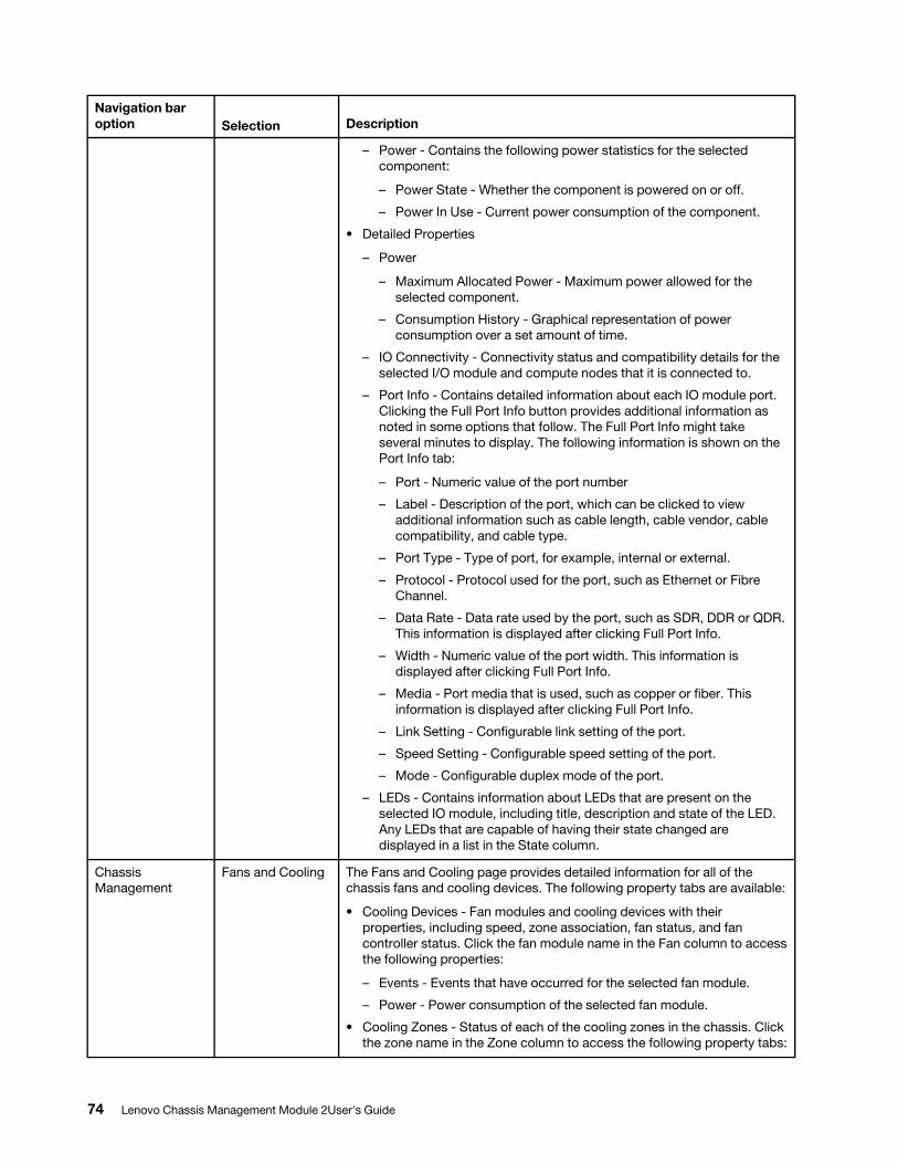
Navigation bar option Selection Description
– Power - Contains the following power statistics for the selected component:
– Power State - Whether the component is powered on or off.
– Power In Use - Current power consumption of the component.
• Detailed Properties
– Power
– Maximum Allocated Power - Maximum power allowed for the selected component.
– Consumption History - Graphical representation of power consumption over a set amount of time.
– IO Connectivity - Connectivity status and compatibility details for the selected I/O module and compute nodes that it is connected to.
– Port Info - Contains detailed information about each IO module port. Clicking the Full Port Info button provides additional information as noted in some options that follow. The Full Port Info might take several minutes to display. The following information is shown on the Port Info tab:
– Port - Numeric value of the port number
– Label - Description of the port, which can be clicked to view additional information such as cable length, cable vendor, cable compatibility, and cable type.
– Port Type - Type of port, for example, internal or external.
– Protocol - Protocol used for the port, such as Ethernet or Fibre Channel.
– Data Rate - Data rate used by the port, such as SDR, DDR or QDR. This information is displayed after clicking Full Port Info.
– Width - Numeric value of the port width. This information is displayed after clicking Full Port Info.
– Media - Port media that is used, such as copper or fiber. This information is displayed after clicking Full Port Info.
– Link Setting - Configurable link setting of the port.
– Speed Setting - Configurable speed setting of the port.
– Mode - Configurable duplex mode of the port.
– LEDs - Contains information about LEDs that are present on the selected IO module, including title, description and state of the LED. Any LEDs that are capable of having their state changed are displayed in a list in the State column.
Chassis Management
Fans and Cooling The Fans and Cooling page provides detailed information for all of the chassis fans and cooling devices. The following property tabs are available:
• Cooling Devices - Fan modules and cooling devices with their properties, including speed, zone association, fan status, and fan controller status. Click the fan module name in the Fan column to access the following properties:
– Events - Events that have occurred for the selected fan module.
– Power - Power consumption of the selected fan module.
• Cooling Zones - Status of each of the cooling zones in the chassis. Click the zone name in the Zone column to access the following property tabs:
74 Lenovo Chassis Management Module 2User's Guide
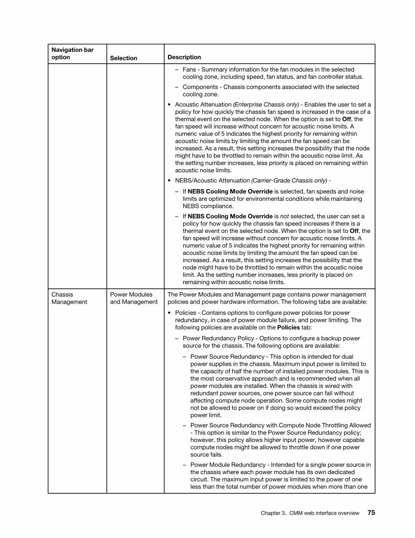
Navigation bar option Selection Description
– Fans - Summary information for the fan modules in the selected cooling zone, including speed, fan status, and fan controller status.
– Components - Chassis components associated with the selected cooling zone.
• Acoustic Attenuation (Enterprise Chassis only) - Enables the user to set a policy for how quickly the chassis fan speed is increased in the case of a thermal event on the selected node. When the option is set to Off, the fan speed will increase without concern for acoustic noise limits. A numeric value of 5 indicates the highest priority for remaining within acoustic noise limits by limiting the amount the fan speed can be increased. As a result, this setting increases the possibility that the node might have to be throttled to remain within the acoustic noise limit. As the setting number increases, less priority is placed on remaining within acoustic noise limits.
• NEBS/Acoustic Attenuation (Carrier-Grade Chassis only) -
– If NEBS Cooling Mode Override is selected, fan speeds and noise limits are optimized for environmental conditions while maintaining NEBS compliance.
– If NEBS Cooling Mode Override is not selected, the user can set a policy for how quickly the chassis fan speed increases if there is a thermal event on the selected node. When the option is set to Off, the fan speed will increase without concern for acoustic noise limits. A numeric value of 5 indicates the highest priority for remaining within acoustic noise limits by limiting the amount the fan speed can be increased. As a result, this setting increases the possibility that the node might have to be throttled to remain within the acoustic noise limit. As the setting number increases, less priority is placed on remaining within acoustic noise limits.
Chassis Management
Power Modules and Management
The Power Modules and Management page contains power management policies and power hardware information. The following tabs are available:
• Policies - Contains options to configure power policies for power redundancy, in case of power module failure, and power limiting. The following policies are available on the Policies tab:
– Power Redundancy Policy - Options to configure a backup power source for the chassis. The following options are available:
– Power Source Redundancy - This option is intended for dual power supplies in the chassis. Maximum input power is limited to the capacity of half the number of installed power modules. This is the most conservative approach and is recommended when all power modules are installed. When the chassis is wired with redundant power sources, one power source can fail without affecting compute node operation. Some compute nodes might not be allowed to power on if doing so would exceed the policy power limit.
– Power Source Redundancy with Compute Node Throttling Allowed - This option is similar to the Power Source Redundancy policy; however, this policy allows higher input power, however capable compute nodes might be allowed to throttle down if one power source fails.
– Power Module Redundancy - Intended for a single power source in the chassis where each power module has its own dedicated circuit. The maximum input power is limited to the power of one less than the total number of power modules when more than one
Chapter 3. CMM web interface overview 75
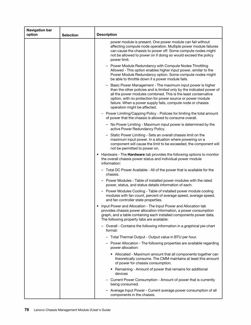
Navigation bar option Selection Description
power module is present. One power module can fail without affecting compute node operation. Multiple power module failures can cause the chassis to power off. Some compute nodes might not be allowed to power on if doing so would exceed the policy power limit.
– Power Module Redundancy with Compute Nodes Throttling Allowed - This option enables higher input power, similar to the Power Module Redundancy option. Some compute nodes might be able to throttle down if a power module fails.
– Basic Power Management - The maximum input power is higher than the other policies and is limited only by the indicated power of all the power modules combined. This is the least conservative option, with no protection for power source or power module failure. When a power supply fails, compute node or chassis operation might be affected.
– Power Limiting/Capping Policy - Policies for limiting the total amount of power that the chassis is allowed to consume overall.
– No Power Limiting - Maximum input power is determined by the active Power Redundancy Policy.
– Static Power Limiting - Sets an overall chassis limit on the maximum input power. In a situation where powering on a component will cause the limit to be exceeded, the component will not be permitted to power on.
• Hardware - The Hardware tab provides the following options to monitor the overall chassis power status and individual power module information:
– Total DC Power Available - All of the power that is available for the chassis.
– Power Modules - Table of installed power modules with the rated power, status, and status details information of each.
– Power Modules Cooling - Table of installed power module cooling modules with fan count, percent of average speed, average speed, and fan controller state properties.
• Input Power and Allocation - The Input Power and Allocation tab provides chassis power allocation information, a power consumption graph, and a table containing each installed components power data. The following property tabs are available:
– Overall - Contains the following information in a graphical pie-chart format:
– Total Thermal Output - Output value in BTU per hour.
– Power Allocation - The following properties are available regarding power allocation:
• Allocated - Maximum amount that all components together can theoretically consume. The CMM maintains at least this amount of power for chassis consumption.
• Remaining - Amount of power that remains for additional devices
– Current Power Consumption - Amount of power that is currently being consumed.
– Average Input Power - Current average power consumption of all components in the chassis.
76 Lenovo Chassis Management Module 2User's Guide
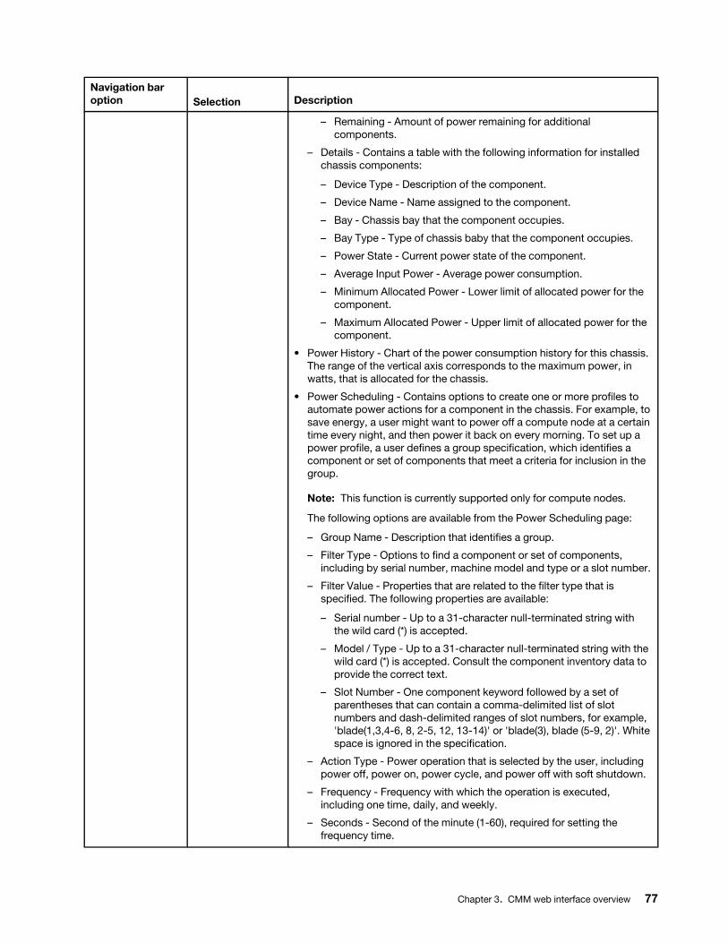
Navigation bar option Selection Description
– Remaining - Amount of power remaining for additional components.
– Details - Contains a table with the following information for installed chassis components:
– Device Type - Description of the component.
– Device Name - Name assigned to the component.
– Bay - Chassis bay that the component occupies.
– Bay Type - Type of chassis baby that the component occupies.
– Power State - Current power state of the component.
– Average Input Power - Average power consumption.
– Minimum Allocated Power - Lower limit of allocated power for the component.
– Maximum Allocated Power - Upper limit of allocated power for the component.
• Power History - Chart of the power consumption history for this chassis. The range of the vertical axis corresponds to the maximum power, in watts, that is allocated for the chassis.
• Power Scheduling - Contains options to create one or more profiles to automate power actions for a component in the chassis. For example, to save energy, a user might want to power off a compute node at a certain time every night, and then power it back on every morning. To set up a power profile, a user defines a group specification, which identifies a component or set of components that meet a criteria for inclusion in the group.
Note: This function is currently supported only for compute nodes.
The following options are available from the Power Scheduling page:
– Group Name - Description that identifies a group.
– Filter Type - Options to find a component or set of components, including by serial number, machine model and type or a slot number.
– Filter Value - Properties that are related to the filter type that is specified. The following properties are available:
– Serial number - Up to a 31-character null-terminated string with the wild card (*) is accepted.
– Model / Type - Up to a 31-character null-terminated string with the wild card (*) is accepted. Consult the component inventory data to provide the correct text.
– Slot Number - One component keyword followed by a set of parentheses that can contain a comma-delimited list of slot numbers and dash-delimited ranges of slot numbers, for example, 'blade(1,3,4-6, 8, 2-5, 12, 13-14)' or 'blade(3), blade (5-9, 2)'. White space is ignored in the specification.
– Action Type - Power operation that is selected by the user, including power off, power on, power cycle, and power off with soft shutdown.
– Frequency - Frequency with which the operation is executed, including one time, daily, and weekly.
– Seconds - Second of the minute (1-60), required for setting the frequency time.
Chapter 3. CMM web interface overview 77
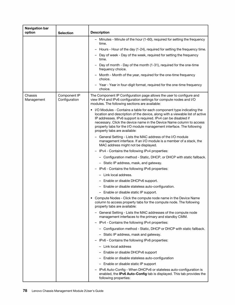
Navigation bar option Selection Description
– Minutes - Minute of the hour (1-60), required for setting the frequency time.
– Hours - Hour of the day (1-24), required for setting the frequency time.
– Day of week - Day of the week, required for setting the frequency time.
– Day of month - Day of the month (1-31), required for the one-time frequency choice.
– Month - Month of the year, required for the one-time frequency choice.
– Year - Year in four-digit format, required for the one-time frequency choice.
Chassis Management
Component IP Configuration
The Component IP Configuration page allows the user to configure and view IPv4 and IPv6 configuration settings for compute nodes and I/O modules. The following sections are available:
• I/O Modules - Contains a table for each component type indicating the location and description of the device, along with a viewable list of active IP addresses. IPv6 support is required. IPv4 can be disabled if necessary. Click the device name in the Device Name column to access property tabs for the I/O module management interface. The following property tabs are available:
– General Setting - Lists the MAC address of the I/O module management interface. If an I/O module is a member of a stack, the MAC address might not be displayed.
– IPv4 - Contains the following IPv4 properties:
– Configuration method - Static, DHCP, or DHCP with static fallback.
– Static IP address, mask, and gateway.
– IPv6 - Contains the following IPv6 properties:
– Link local address.
– Enable or disable DHCPv6 support.
– Enable or disable stateless auto-configuration.
– Enable or disable static IP support.
• Compute Nodes - Click the compute node name in the Device Name column to access property tabs for the compute node. The following property tabs are available:
– General Setting - Lists the MAC addresses of the compute node management interfaces to the primary and standby CMM.
– IPv4 - Contains the following IPv4 properties:
– Configuration method - Static, DHCP or DHCP with static fallback.
– Static IP address, mask and gateway.
– IPv6 - Contains the following IPv6 properties:
– Link local address
– Enable or disable DHCPv6 support
– Enable or disable stateless auto-configuration
– Enable or disable static IP support
– IPv6 Auto-Config - When DHCPv6 or stateless auto-configuration is enabled, the IPv6 Auto-Config tab is displayed. This tab provides the following properties:
78 Lenovo Chassis Management Module 2User's Guide
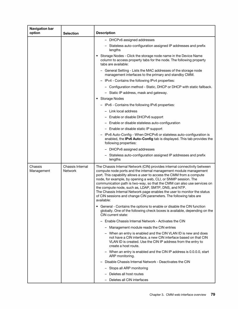
Navigation bar option Selection Description
– DHCPv6 assigned addresses
– Stateless auto-configuration assigned IP addresses and prefix lengths
• Storage Nodes - Click the storage node name in the Device Name column to access property tabs for the node. The following property tabs are available:
– General Setting - Lists the MAC addresses of the storage node management interfaces to the primary and standby CMM.
– IPv4 - Contains the following IPv4 properties:
– Configuration method - Static, DHCP or DHCP with static fallback.
– Static IP address, mask and gateway.
• Storage Nodes
– IPv6 - Contains the following IPv6 properties:
– Link local address
– Enable or disable DHCPv6 support
– Enable or disable stateless auto-configuration
– Enable or disable static IP support
– IPv6 Auto-Config - When DHCPv6 or stateless auto-configuration is enabled, the IPv6 Auto-Config tab is displayed. This tab provides the following properties:
– DHCPv6 assigned addresses
– Stateless auto-configuration assigned IP addresses and prefix lengths
Chassis Management
Chassis Internal Network
The Chassis Internal Network (CIN) provides internal connectivity between compute node ports and the internal management module management port. This capability allows a user to access the CMM from a compute node, for example, by opening a web, CLI, or SNMP session. The communication path is two-way, so that the CMM can also use services on the compute node, such as, LDAP, SMTP, DNS, and NTP. The Chassis Internal Network page enables the user to monitor the status of CIN sessions and change CIN parameters. The following tabs are available:
• General - Contains the options to enable or disable the CIN function globally. One of the following check boxes is available, depending on the CIN current state:
– Enable Chassis Internal Network - Activates the CIN
– Management module reads the CIN entries
– When an entry is enabled and the CIN VLAN ID is new and does not have a CIN interface, a new CIN interface based on that CIN VLAN ID is created. Use the CIN IP address from the entry to create a host route.
– When an entry is enabled and the CIN IP address is 0.0.0.0, start ARP monitoring.
– Disable Chassis Internal Network - Deactivates the CIN
– Stops all ARP monitoring
– Deletes all host routes
– Deletes all CIN interfaces
Chapter 3. CMM web interface overview 79
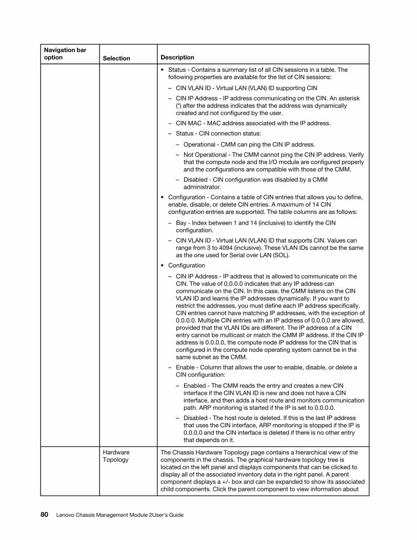
Navigation bar option Selection Description
• Status - Contains a summary list of all CIN sessions in a table. The following properties are available for the list of CIN sessions:
– CIN VLAN ID - Virtual LAN (VLAN) ID supporting CIN
– CIN IP Address - IP address communicating on the CIN. An asterisk (*) after the address indicates that the address was dynamically created and not configured by the user.
– CIN MAC - MAC address associated with the IP address.
– Status - CIN connection status:
– Operational - CMM can ping the CIN IP address.
– Not Operational - The CMM cannot ping the CIN IP address. Verify that the compute node and the I/O module are configured properly and the configurations are compatible with those of the CMM.
– Disabled - CIN configuration was disabled by a CMM administrator.
• Configuration - Contains a table of CIN entries that allows you to define, enable, disable, or delete CIN entries. A maximum of 14 CIN configuration entries are supported. The table columns are as follows:
– Bay - Index between 1 and 14 (inclusive) to identify the CIN configuration.
– CIN VLAN ID - Virtual LAN (VLAN) ID that supports CIN. Values can range from 3 to 4094 (inclusive). These VLAN IDs cannot be the same as the one used for Serial over LAN (SOL).
• Configuration
– CIN IP Address - IP address that is allowed to communicate on the CIN. The value of 0.0.0.0 indicates that any IP address can communicate on the CIN. In this case, the CMM listens on the CIN VLAN ID and learns the IP addresses dynamically. If you want to restrict the addresses, you must define each IP address specifically. CIN entries cannot have matching IP addresses, with the exception of 0.0.0.0. Multiple CIN entries with an IP address of 0.0.0.0 are allowed, provided that the VLAN IDs are different. The IP address of a CIN entry cannot be multicast or match the CMM IP address. If the CIN IP address is 0.0.0.0, the compute node IP address for the CIN that is configured in the compute node operating system cannot be in the same subnet as the CMM.
– Enable - Column that allows the user to enable, disable, or delete a CIN configuration:
– Enabled - The CMM reads the entry and creates a new CIN interface if the CIN VLAN ID is new and does not have a CIN interface, and then adds a host route and monitors communication path. ARP monitoring is started if the IP is set to 0.0.0.0.
– Disabled - The host route is deleted. If this is the last IP address that uses the CIN interface, ARP monitoring is stopped if the IP is 0.0.0.0 and the CIN interface is deleted if there is no other entry that depends on it.
Hardware Topology
The Chassis Hardware Topology page contains a hierarchical view of the components in the chassis. The graphical hardware topology tree is located on the left panel and displays components that can be clicked to display all of the associated inventory data in the right panel. A parent component displays a +/- box and can be expanded to show its associated child components. Click the parent component to view information about
80 Lenovo Chassis Management Module 2User's Guide
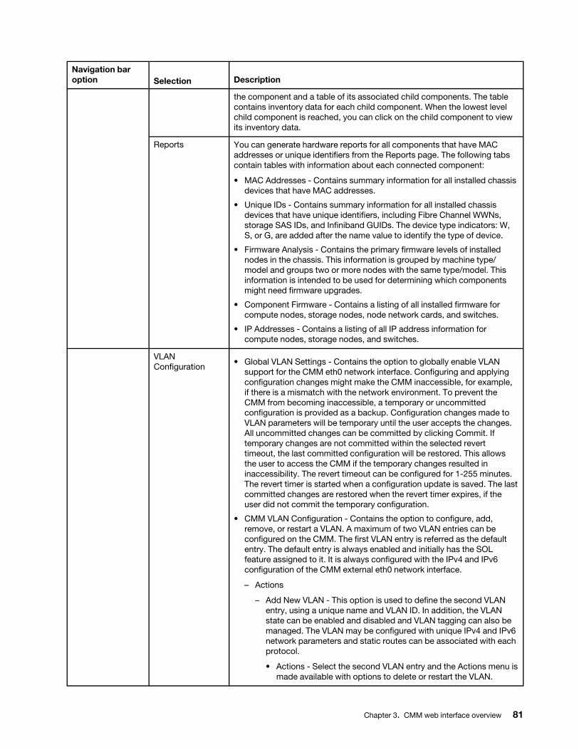
Navigation bar option Selection Description
the component and a table of its associated child components. The table contains inventory data for each child component. When the lowest level child component is reached, you can click on the child component to view its inventory data.
Reports You can generate hardware reports for all components that have MAC addresses or unique identifiers from the Reports page. The following tabs contain tables with information about each connected component:
• MAC Addresses - Contains summary information for all installed chassis devices that have MAC addresses.
• Unique IDs - Contains summary information for all installed chassis devices that have unique identifiers, including Fibre Channel WWNs, storage SAS IDs, and Infiniband GUIDs. The device type indicators: W, S, or G, are added after the name value to identify the type of device.
• Firmware Analysis - Contains the primary firmware levels of installed nodes in the chassis. This information is grouped by machine type/ model and groups two or more nodes with the same type/model. This information is intended to be used for determining which components might need firmware upgrades.
• Component Firmware - Contains a listing of all installed firmware for compute nodes, storage nodes, node network cards, and switches.
• IP Addresses - Contains a listing of all IP address information for compute nodes, storage nodes, and switches.
VLAN Configuration • Global VLAN Settings - Contains the option to globally enable VLAN
support for the CMM eth0 network interface. Configuring and applying configuration changes might make the CMM inaccessible, for example, if there is a mismatch with the network environment. To prevent the CMM from becoming inaccessible, a temporary or uncommitted configuration is provided as a backup. Configuration changes made to VLAN parameters will be temporary until the user accepts the changes. All uncommitted changes can be committed by clicking Commit. If temporary changes are not committed within the selected revert timeout, the last committed configuration will be restored. This allows the user to access the CMM if the temporary changes resulted in inaccessibility. The revert timeout can be configured for 1-255 minutes. The revert timer is started when a configuration update is saved. The last committed changes are restored when the revert timer expires, if the user did not commit the temporary configuration.
• CMM VLAN Configuration - Contains the option to configure, add, remove, or restart a VLAN. A maximum of two VLAN entries can be configured on the CMM. The first VLAN entry is referred as the default entry. The default entry is always enabled and initially has the SOL feature assigned to it. It is always configured with the IPv4 and IPv6 configuration of the CMM external eth0 network interface.
– Actions
– Add New VLAN - This option is used to define the second VLAN entry, using a unique name and VLAN ID. In addition, the VLAN state can be enabled and disabled and VLAN tagging can also be managed. The VLAN may be configured with unique IPv4 and IPv6 network parameters and static routes can be associated with each protocol.
• Actions - Select the second VLAN entry and the Actions menu is made available with options to delete or restart the VLAN.
Chapter 3. CMM web interface overview 81

Navigation bar option Selection Description
– Delete VLAN - This option is used to delete the second VLAN entry.
• Features Assignment - Assigns the available features to a VLAN, or removes the feature assignment.
CMM management optionsYou configure only the active CMM. If a standby CMM is installed, it receives the configuration and status information automatically from the active CMM.
When the Flex System chassis is started for the first time, the CMM automatically configures its remote management port, enabling you to establish a management connection. See "Configuring the CMM for remote access" in the Lenovo Chassis Management Module 2 Installation Guide for information.
Notes:
• Each CMM is configured with the same static IP address. You must create a unique static IP address for each CMM. If DHCP is not used, only one CMM at a time can be added onto the network for discovery. Adding more than one CMM to the network without a unique IP address assignment for each results in IP address conflicts.
• For more information about CMM redundancy, see "Preparing for CMM redundancy" in the Lenovo Flex System Chassis Management Module 2 Installation Guide.
• The CMM default user ID and password are used by the Lenovo XClarity Administrator or the Flex System Manager management software to access Power Systems compute nodes in a chassis. Before you update the firmware for one or more Power Systems compute nodes with the management software, make sure that the password for the CMM default user ID account will not expire before the update is complete. If the password expires during a code update, the Power Systems compute nodes might not reconnect to the management software, and each Power Systems compute node might have to be updated with the new password. See the User Accounts page (click Mgt Module Management > User Accounts) in the CMM web interface, or the users command in the CMM Command-Line Interface Reference Guide, for information about how to check a password expiration date and change the password, if necessary.
If the CMM that is being installed is a replacement for the only CMM in the chassis and you saved the configuration file before you replaced the CMM, you can apply the saved configuration file to the replacement CMM. A saved configuration is applied from the Mgt Module Management page. Click Configuration from the Mgt Module Management menu.
You can purchase activation keys to activate the Features on Demand features for your CMM and I/O modules, if your I/O modules support these features. Click License Key Management from the Mgt Module Management menu.
You can configure the CMM by using the CMM Initial Setup wizard. The setup wizard starts automatically when you access the web interface of a new CMM for the first time. It also starts automatically the first time that you access the web interface of a CMM that has been reset to its default settings. To access the setup wizard, click Mgt Module Management, click Configuration, and then click Initial Setup Wizard.
Note: You can also configure the CMM by using the optional Lenovo XClarity Administrator (see http:// flexsystem.lenovofiles.com/help/topic/com.lenovo.lxca.doc/aug_product_page.html) or the Flex System Manager management software (see Flex System Manager Software Installation and Service Guide).
Attention: Installing the wrong firmware update might cause the CMM to malfunction. Before you install a firmware update, read any readme and change history files that are provided with the downloaded update.
82 Lenovo Chassis Management Module 2User's Guide
These files contain important information about the update and the procedure for installing the update, including any special procedure for updating from an early firmware version to the latest version.
The following table describes the options that are available from the Mgt Module Management menu.
Navigation bar option Selection Description
Mgt Module Management
You can access CMM management options from the Mgt Module Management menu.
Chapter 3. CMM web interface overview 83

Navigation bar option Selection Description
User Accounts The User Accounts page enables the user to define login accounts to access the CMM through the web interface. Note: CMM user accounts are also used to log in to the service processor interfaces of compute nodes.The following information and options are available from the User Accounts page:
• Accounts - Contains a table of defined users with information related to each user account, and some options for managing user accounts. The following options and account information are included:
– User Name - Click the user name to open User Properties, which enables the user to change or configure existing user information. The following pages are available:
– General - Change the password for the selected user account or update the simultaneous active session count.
– Permission Group - Change the permission group that is associated with the selected user name.
– SNMPv3 - Configure SNMPv3 information including context name, authentication protocol, privacy protocol, request access type, and trap destination IP address or host name.
– SSH Client Public Key - Import and manage up to four SSH keys used for SSH public key authentication. This option allows secure CLI access, using SSH without the need for a user-supplied password.
– Number of active sessions - Number of active sessions for the user account.
– Last Login - Last time and date the user account was authenticated.
– Dormant - Indicates whether the user account is dormant, according to the current user account security policy of the chassis. When an X is present, the account is dormant. When the account is no longer dormant, the X is not be present. To recover an account from a dormant state, the user must log in to the dormant account. No changes can be made to the user account settings while the account is in a dormant state.
– Days to password expiration - When password expiration is enabled, this value indicates the amount of days that the user account will remain active. The default is 90 days, and the maximal is 365 days. When the value is set to zero, the passwords will never expire.
– Days since password expiration warning to password expiration: When password expiration warning is enabled, this value indicates the amount of days that the user will receive warnings before the password expires. The default is five days, and the minimal is one day. It cannot exceed the value specified for days to password expiration. When the value is set to zero, the user will never be warned about password expiration.
– Times of Password reuse cycle - This value indicates the amount of times of using unique passwords before a users can reuse a previously used combination for password. The default is five times, and the maximal is ten. When the value is set to 0, any previously used passwords may be reused anytime.
– Hours of password change interval - This value indicates the amount of hours a combination must endure before the user can
84 Lenovo Chassis Management Module 2User's Guide
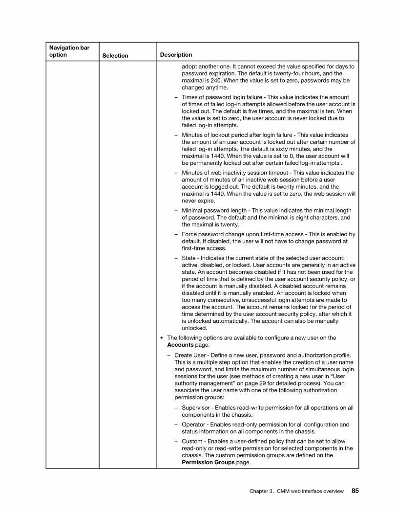
Navigation bar option Selection Description
adopt another one. It cannot exceed the value specified for days to password expiration. The default is twenty-four hours, and the maximal is 240. When the value is set to zero, passwords may be changed anytime.
– Times of password login failure - This value indicates the amount of times of failed log-in attempts allowed before the user account is locked out. The default is five times, and the maximal is ten. When the value is set to zero, the user account is never locked due to failed log-in attempts.
– Minutes of lockout period after login failure - This value indicates the amount of an user account is locked out after certain number of failed log-in attempts. The default is sixty minutes, and the maximal is 1440. When the value is set to 0, the user account will be permanently locked out after certain failed log-in attempts .
– Minutes of web inactivity session timeout - This value indicates the amount of minutes of an inactive web session before a user account is logged out. The default is twenty minutes, and the maximal is 1440. When the value is set to zero, the web session will never expire.
– Minimal password length - This value indicates the minimal length of password. The default and the minimal is eight characters, and the maximal is twenty.
– Force password change upon first-time access - This is enabled by default. If disabled, the user will not have to change password at first-time access.
– State - Indicates the current state of the selected user account: active, disabled, or locked. User accounts are generally in an active state. An account becomes disabled if it has not been used for the period of time that is defined by the user account security policy, or if the account is manually disabled. A disabled account remains disabled until it is manually enabled. An account is locked when too many consecutive, unsuccessful login attempts are made to access the account. The account remains locked for the period of time determined by the user account security policy, after which it is unlocked automatically. The account can also be manually unlocked.
• The following options are available to configure a new user on the Accounts page:
– Create User - Define a new user, password and authorization profile. This is a multiple step option that enables the creation of a user name and password, and limits the maximum number of simultaneous login sessions for the user (see methods of creating a new user in “User authority management” on page 29 for detailed process). You can associate the user name with one of the following authorization permission groups:
– Supervisor - Enables read-write permission for all operations on all components in the chassis.
– Operator - Enables read-only permission for all configuration and status information on all components in the chassis.
– Custom - Enables a user-defined policy that can be set to allow read-only or read-write permission for selected components in the chassis. The custom permission groups are defined on the Permission Groups page.
Chapter 3. CMM web interface overview 85
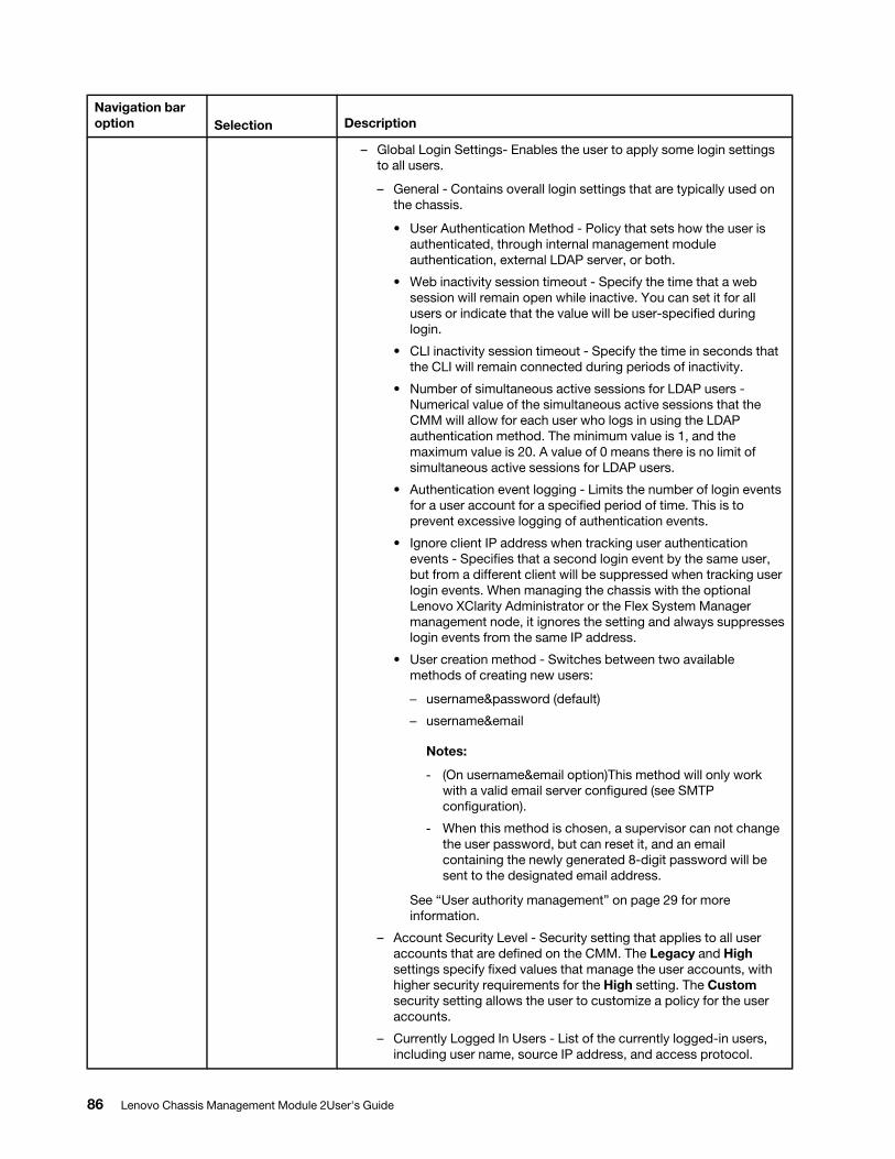
Navigation bar option Selection Description
– Global Login Settings- Enables the user to apply some login settings to all users.
– General - Contains overall login settings that are typically used on the chassis.
• User Authentication Method - Policy that sets how the user is authenticated, through internal management module authentication, external LDAP server, or both.
• Web inactivity session timeout - Specify the time that a web session will remain open while inactive. You can set it for all users or indicate that the value will be user-specified during login.
• CLI inactivity session timeout - Specify the time in seconds that the CLI will remain connected during periods of inactivity.
• Number of simultaneous active sessions for LDAP users - Numerical value of the simultaneous active sessions that the CMM will allow for each user who logs in using the LDAP authentication method. The minimum value is 1, and the maximum value is 20. A value of 0 means there is no limit of simultaneous active sessions for LDAP users.
• Authentication event logging - Limits the number of login events for a user account for a specified period of time. This is to prevent excessive logging of authentication events.
• Ignore client IP address when tracking user authentication events - Specifies that a second login event by the same user, but from a different client will be suppressed when tracking user login events. When managing the chassis with the optional Lenovo XClarity Administrator or the Flex System Manager management node, it ignores the setting and always suppresses login events from the same IP address.
• User creation method - Switches between two available methods of creating new users:
– username&password (default)
– username&email
Notes:
- (On username&email option)This method will only work with a valid email server configured (see SMTPconfiguration).
- When this method is chosen, a supervisor can not change the user password, but can reset it, and an email containing the newly generated 8-digit password will be sent to the designated email address.
See “User authority management” on page 29 for more information.
– Account Security Level - Security setting that applies to all user accounts that are defined on the CMM. The Legacy and High settings specify fixed values that manage the user accounts, with higher security requirements for the High setting. The Custom security setting allows the user to customize a policy for the user accounts.
– Currently Logged In Users - List of the currently logged-in users, including user name, source IP address, and access protocol.
86 Lenovo Chassis Management Module 2User's Guide
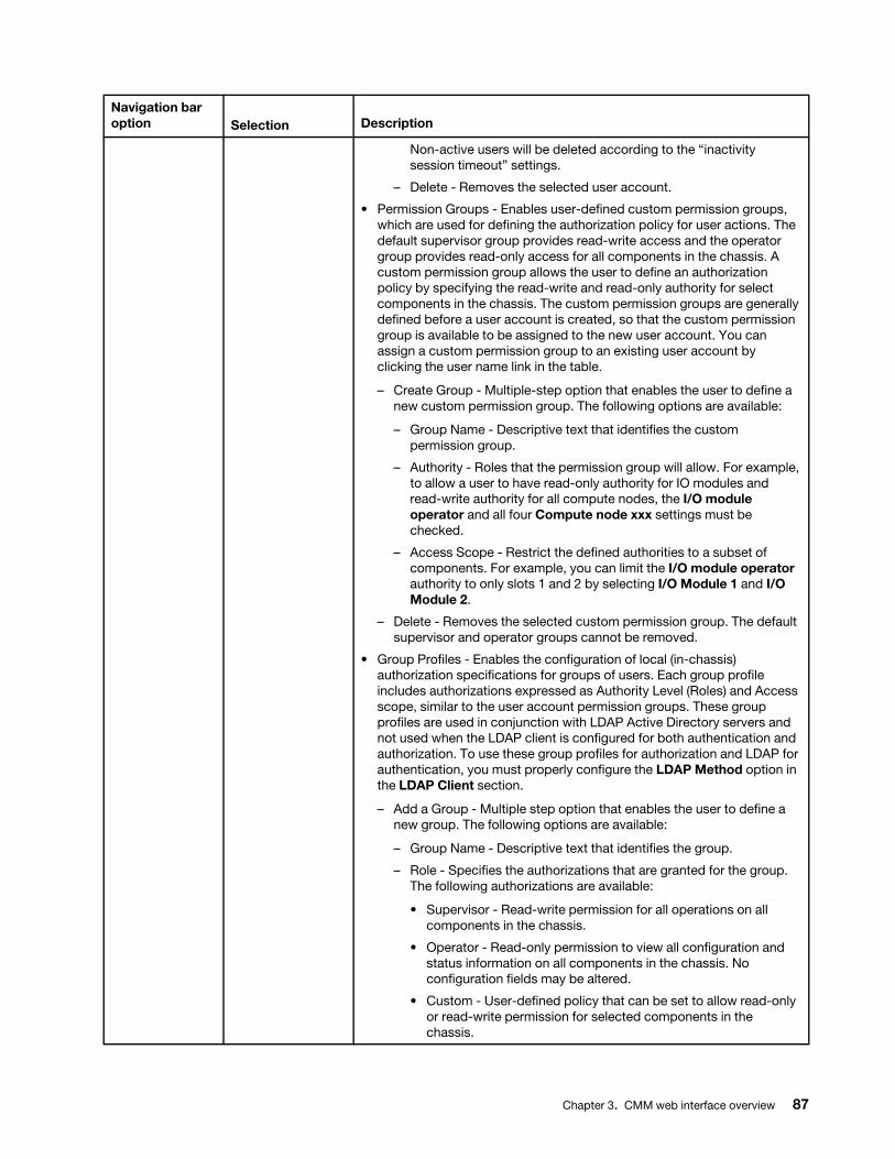
Navigation bar option Selection Description
Non-active users will be deleted according to the “inactivity session timeout” settings.
– Delete - Removes the selected user account.
• Permission Groups - Enables user-defined custom permission groups, which are used for defining the authorization policy for user actions. The default supervisor group provides read-write access and the operator group provides read-only access for all components in the chassis. A custom permission group allows the user to define an authorization policy by specifying the read-write and read-only authority for select components in the chassis. The custom permission groups are generally defined before a user account is created, so that the custom permission group is available to be assigned to the new user account. You can assign a custom permission group to an existing user account by clicking the user name link in the table.
– Create Group - Multiple-step option that enables the user to define a new custom permission group. The following options are available:
– Group Name - Descriptive text that identifies the custom permission group.
– Authority - Roles that the permission group will allow. For example, to allow a user to have read-only authority for IO modules and read-write authority for all compute nodes, the I/O module operator and all four Compute node xxx settings must be checked.
– Access Scope - Restrict the defined authorities to a subset of components. For example, you can limit the I/O module operator authority to only slots 1 and 2 by selecting I/O Module 1 and I/O Module 2.
– Delete - Removes the selected custom permission group. The default supervisor and operator groups cannot be removed.
• Group Profiles - Enables the configuration of local (in-chassis) authorization specifications for groups of users. Each group profile includes authorizations expressed as Authority Level (Roles) and Access scope, similar to the user account permission groups. These group profiles are used in conjunction with LDAP Active Directory servers and not used when the LDAP client is configured for both authentication and authorization. To use these group profiles for authorization and LDAP for authentication, you must properly configure the LDAP Method option in the LDAP Client section.
– Add a Group - Multiple step option that enables the user to define a new group. The following options are available:
– Group Name - Descriptive text that identifies the group.
– Role - Specifies the authorizations that are granted for the group. The following authorizations are available:
• Supervisor - Read-write permission for all operations on all components in the chassis.
• Operator - Read-only permission to view all configuration and status information on all components in the chassis. No configuration fields may be altered.
• Custom - User-defined policy that can be set to allow read-only or read-write permission for selected components in the chassis.
Chapter 3. CMM web interface overview 87
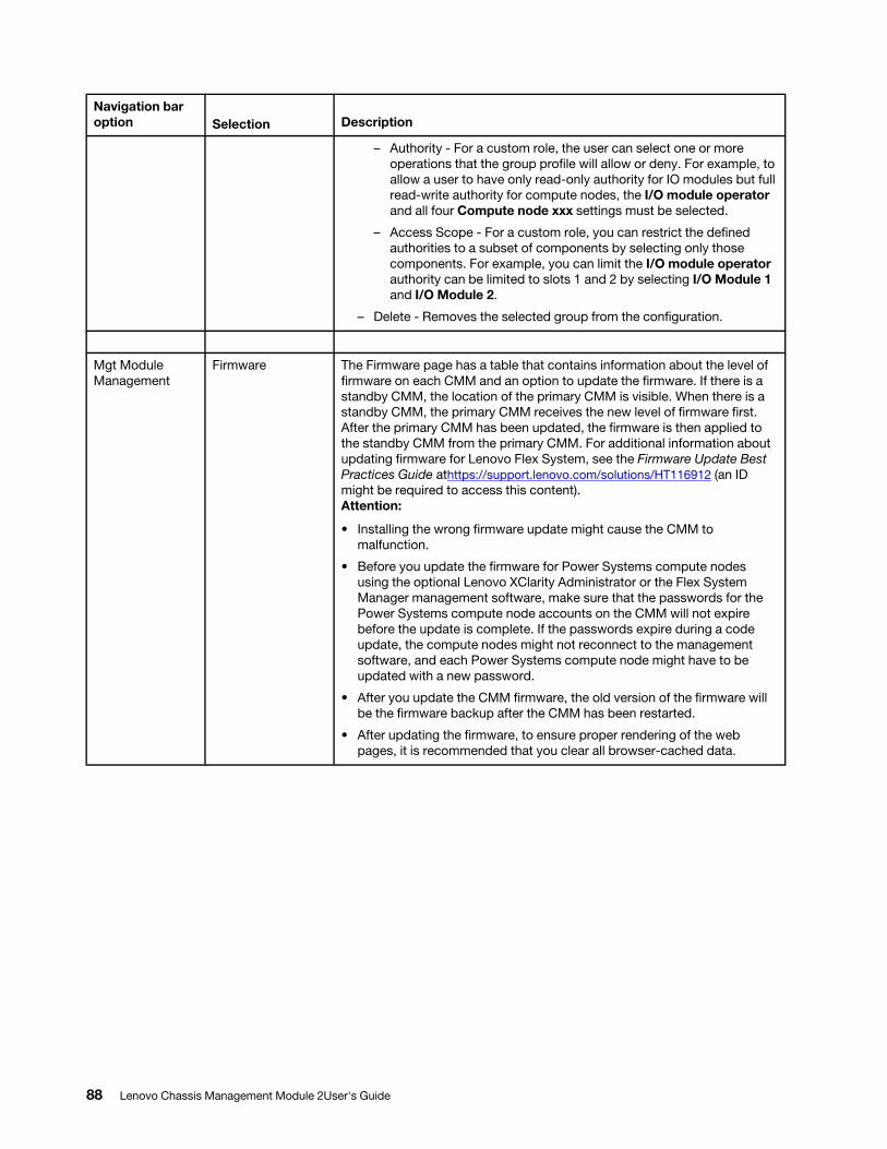
Navigation bar option Selection Description
– Authority - For a custom role, the user can select one or more operations that the group profile will allow or deny. For example, to allow a user to have only read-only authority for IO modules but full read-write authority for compute nodes, the I/O module operator and all four Compute node xxx settings must be selected.
– Access Scope - For a custom role, you can restrict the defined authorities to a subset of components by selecting only those components. For example, you can limit the I/O module operator authority can be limited to slots 1 and 2 by selecting I/O Module 1 and I/O Module 2.
– Delete - Removes the selected group from the configuration.
Mgt Module Management
Firmware The Firmware page has a table that contains information about the level of firmware on each CMM and an option to update the firmware. If there is a standby CMM, the location of the primary CMM is visible. When there is a standby CMM, the primary CMM receives the new level of firmware first. After the primary CMM has been updated, the firmware is then applied to the standby CMM from the primary CMM. For additional information about updating firmware for Lenovo Flex System, see the Firmware Update Best Practices Guide athttps://support.lenovo.com/solutions/HT116912 (an ID might be required to access this content). Attention:
• Installing the wrong firmware update might cause the CMM to malfunction.
• Before you update the firmware for Power Systems compute nodes using the optional Lenovo XClarity Administrator or the Flex System Manager management software, make sure that the passwords for the Power Systems compute node accounts on the CMM will not expire before the update is complete. If the passwords expire during a code update, the compute nodes might not reconnect to the management software, and each Power Systems compute node might have to be updated with a new password.
• After you update the CMM firmware, the old version of the firmware will be the firmware backup after the CMM has been restarted.
• After updating the firmware, to ensure proper rendering of the web pages, it is recommended that you clear all browser-cached data.
88 Lenovo Chassis Management Module 2User's Guide
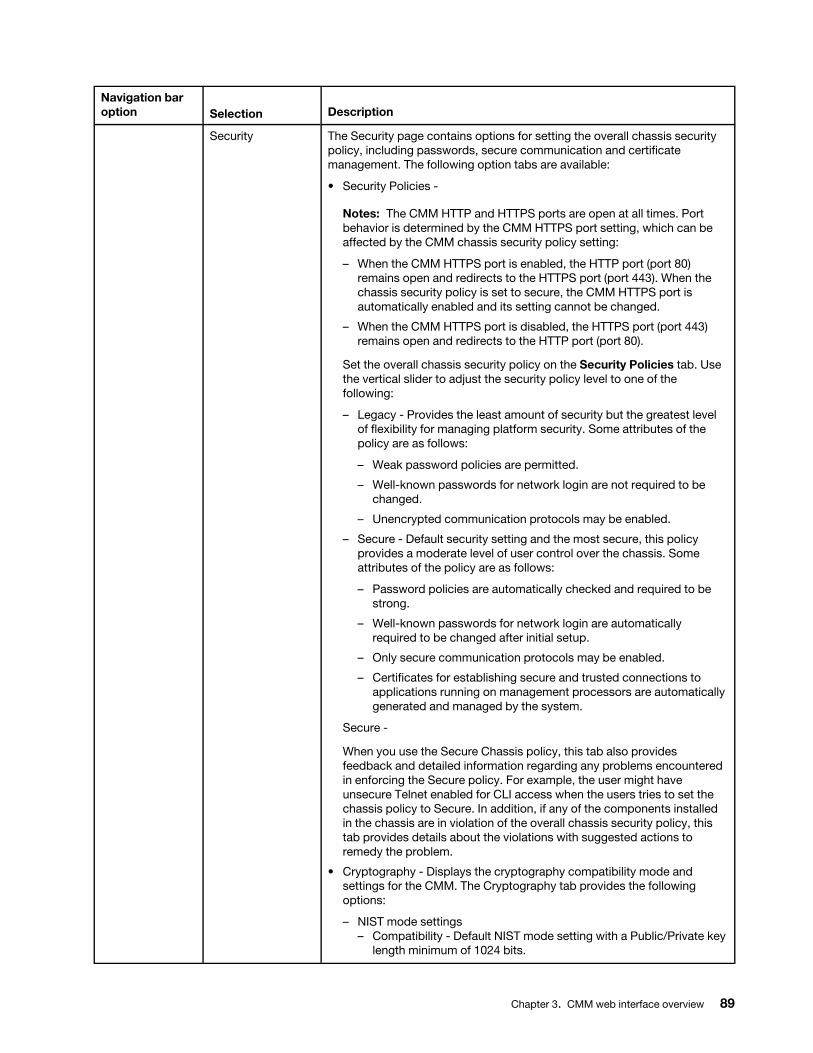
Navigation bar option Selection Description
Security The Security page contains options for setting the overall chassis security policy, including passwords, secure communication and certificate management. The following option tabs are available:
• Security Policies -
Notes: The CMM HTTP and HTTPS ports are open at all times. Port behavior is determined by the CMM HTTPS port setting, which can be affected by the CMM chassis security policy setting:
– When the CMM HTTPS port is enabled, the HTTP port (port 80) remains open and redirects to the HTTPS port (port 443). When the chassis security policy is set to secure, the CMM HTTPS port is automatically enabled and its setting cannot be changed.
– When the CMM HTTPS port is disabled, the HTTPS port (port 443) remains open and redirects to the HTTP port (port 80).
Set the overall chassis security policy on the Security Policies tab. Use the vertical slider to adjust the security policy level to one of the following:
– Legacy - Provides the least amount of security but the greatest level of flexibility for managing platform security. Some attributes of the policy are as follows:
– Weak password policies are permitted.
– Well-known passwords for network login are not required to be changed.
– Unencrypted communication protocols may be enabled.
– Secure - Default security setting and the most secure, this policy provides a moderate level of user control over the chassis. Some attributes of the policy are as follows:
– Password policies are automatically checked and required to be strong.
– Well-known passwords for network login are automatically required to be changed after initial setup.
– Only secure communication protocols may be enabled.
– Certificates for establishing secure and trusted connections to applications running on management processors are automatically generated and managed by the system.
Secure -
When you use the Secure Chassis policy, this tab also provides feedback and detailed information regarding any problems encountered in enforcing the Secure policy. For example, the user might have unsecure Telnet enabled for CLI access when the users tries to set the chassis policy to Secure. In addition, if any of the components installed in the chassis are in violation of the overall chassis security policy, this tab provides details about the violations with suggested actions to remedy the problem.
• Cryptography - Displays the cryptography compatibility mode and settings for the CMM. The Cryptography tab provides the following options:
– NIST mode settings – Compatibility - Default NIST mode setting with a Public/Private key
length minimum of 1024 bits.
Chapter 3. CMM web interface overview 89
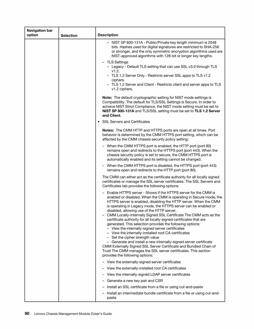
Navigation bar option Selection Description
– NIST SP 800-131A - Public/Private key length minimum is 2048 bits. Hashes used for digital signatures are restricted to SHA-256 or stronger, and the only symmetric encryption algorithms used are NIST-approved algorithms with 128-bit or longer key lengths.
– TLS Settings – Legacy - Default TLS setting that can use SSL v3.0 through TLS
v1.2.– TLS 1.2 Server Only - Restricts server SSL apps to TLS v1.2
ciphers.– TLS 1.2 Server and Client - Restricts client and server apps to TLS
v1.2 ciphers.
Note: The default cryptographic setting for NIST mode settings is Compatibility. The default for TLS/SSL Settings is Secure. In order to achieve NIST Strict Compliance, the NIST mode setting must be set to NIST SP 800-131A and TLS/SSL setting must be set to TLS 1.2 Server and Client.
• SSL Servers and Certificates
Notes: The CMM HTTP and HTTPS ports are open at all times. Port behavior is determined by the CMM HTTPS port setting, which can be affected by the CMM chassis security policy setting:
– When the CMM HTTPS port is enabled, the HTTP port (port 80) remains open and redirects to the HTTPS port (port 443). When the chassis security policy is set to secure, the CMM HTTPS port is automatically enabled and its setting cannot be changed.
– When the CMM HTTPS port is disabled, the HTTPS port (port 443) remains open and redirects to the HTTP port (port 80).
The CMM can either act as the certificate authority for all locally signed certificates or manage the SSL server certificates. The SSL Servers and Certificates tab provides the following options:
– Enable HTTPS server - Shows if the HTTPS server for the CMM is enabled or disabled. When the CMM is operating in Secure mode, the HTTPS server is enabled, disabling the HTTP server. When the CMM is operating in Legacy mode, the HTTPS server can be enabled or disabled, allowing use of the HTTP server.
– CMM Locally-Internally Signed SSL Certificate The CMM acts as the certificate authority for all locally-signed certificates that are generated. This selection provides the following options: – View the internally-signed server certificates– View the internally-installed root CA certificates– Set the cipher strength value– Generate and install a new internally-signed server certificate
CMM Externally Signed SSL Server Certificate and Bundled Chain of Trust The CMM manages the SSL server certificates. This section provides the following options:
– View the externally-signed server certificates
– View the externally-installed root CA certificates
– View the internally-signed LDAP server certificates
– Generate a new key pair and CSR
– Install an SSL certificate from a file or using cut-and-paste
– Install an intermediate bundle certificate from a file or using cut-and- paste
90 Lenovo Chassis Management Module 2User's Guide
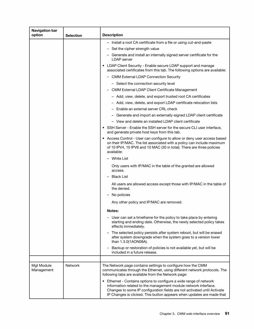
Navigation bar option Selection Description
– Install a root CA certificate from a file or using cut-and-paste
– Set the cipher strength value
– Generate and install an internally signed server certificate for the LDAP server
• LDAP Client Security - Enable secure LDAP support and manage associated certificates from this tab. The following options are available:
– CMM External LDAP Connection Security
– Select the connection security level
– CMM External LDAP Client Certificate Management
– Add, view, delete, and export trusted root CA certificates
– Add, view, delete, and export LDAP certificate relocation lists
– Enable an external server CRL check
– Generate and import an externally-signed LDAP client certificate
– View and delete an installed LDAP client certificate
• SSH Server - Enable the SSH server for the secure CLI user interface, and generate private host keys from this tab.
• Access Control - User can configure to allow or deny user access based on their IP/MAC. The list associated with a policy can include maximum of 10 IPV4, 10 IPV6 and 10 MAC (30 in total). There are three policies available:
– White List
Only users with IP/MAC in the table of the granted are allowed access.
– Black List
All users are allowed access except those with IP/MAC in the table of the denied.
– No policies
Any other policy and IP/MAC are removed.
Notes:
– User can set a timeframe for the policy to take place by entering starting and ending date. Otherwise, the newly selected policy takes effects immediately.
– The selected policy persists after system reboot, but will be erased after system downgrade when the system goes to a version lower than 1.3.0(1AON08A).
– Backup or restoration of policies is not available yet, but will be included in a future release.
Mgt Module Management
Network The Network page contains settings to configure how the CMM communicates through the Ethernet, using different network protocols. The following tabs are available from the Network page:
• Ethernet - Contains options to configure a wide range of network information related to the management module network interface. Changes to some IP configuration fields are not activated until Activate IP Changes is clicked. This button appears when updates are made that
Chapter 3. CMM web interface overview 91

Navigation bar option Selection Description
are different from the current values for the eth0 interface. The following information is included in this section:
Note: If you enable IP address swapping during failover with both CMMs set to the same static IP address, you must disable DHCP.
– Host name and domain name
– IPv4 - Contains addressing information and IP address assignment preference (DHCP, Static, or DHCP then Static).
– IPv6 - Contains addressing information, including static, stateless address configuration and DHCPv6 stateful.
– Advanced Ethernet - Contains the following Ethernet properties and options:
– Duplex setting, MTU, and data rate
– MAC address specification
– Failover policy settings for physical and logical link loss
– Logical link check addresses and policy
• SNMP - Options for configuring the SNMP user interface support. The following options are available:
– Enable SNMPv1 agent - Enables definition of three SNMPv1 community names. The Community tab is visible after the option is selected. Create communties by entering a community name, access type, and up to three SNMP manager addresses, which can be a host name or an IPv4 or IPv6 address. The host name and addresses are also used as the destination for SNMP traps. A value of 0.0.0.0 or 0::0 can be specified to indicate ANY manager; however, those two special addresses cannot be used as trap destinations.
– Enable SNMPv3 agent - This option is enabled on the SNMP tab; however, SNMPv3 is user-based and is configured on the User Accounts page. After a user is defined, click the name link and complete the configuration on the SNMPv3 tab.
– Contact - Define a contact and specify system location information.
– Traps - Enable the sending of SNMP traps.
• DNS - Enable DNS to include additional DNS server addresses in the search order for host-name-to-IP address resolution. DNS lookup is always enabled, and other DNS addresses may be automatically assigned by the DHCP server when DHCP is in use. Additional DNS servers are added to the top of the search list, so the host name search is done on these servers before it happens on a DNS server that is automatically assigned by a DHCP sever.
• SMTP- Configure a SMTP server and domain name. This protocol is used to forward service data, events and initial password of a new user name to an email recipient.
• LDAP Client - The CMM contains an LDAP client that can be configured to provide user authentication through one or more LDAP servers. The LDAP servers that are used for authentication can be discovered dynamically or manually searched. The CMM supports three remote authentication models, which use the LDAP servers to authenticate users. You can select the option to be used from the list. The following models are supported:
– Active Directory Authentication Only - Applies to an Active Directory (AD) environment only. Only the AD servers are used to authenticate
92 Lenovo Chassis Management Module 2User's Guide

Navigation bar option Selection Description
users. No authorization information is stored on the AD server for any user. This means that the CMM must be configured with user authorization information.
– Active Directory Role Based Authentication and Authorization - Applies to an AD environment only. This option relies on configuration stored on the AD server to associate permissions with some users, and is used to authenticate and authorize users through some AD servers. Enable this option by completing the following from the LDAP Client tab:
– Select the Use LDAP Servers for Authentication and Authorization option.
– Select the Use Pre-configured servers or Use DNS to find LDAP Servers option.
– Check the Enable enhanced role-based security checkbox.
– Legacy Authentication and Authorization - Supports AD, Novell eDirectory, and OpenLDAP environments. This option relies on configuration stored on the LDAP server to associate permissions with some users. Use this option to authenticate and authorize users through some LDAP servers. To enable this option, complete the following steps:
1. Select Use LDAP Servers for Authentication and Authorization.
2. Clear the Enable enhanced role-based security check box to disable the option.
• LDAP Client -
– TCP Command Mode - Enables TCP command mode protocol for an external application to manage the CMM using the Lenovo XClarity Administrator or the Flex System Manager software. The configuration enables non-secure and secure modes of operation and allows the user to specify a maximum number of connections and an inactivity timeout value.
– SLP - Enables the Service Location Protocol (SLP), which the CMM uses to discover other CMMs in the network. This must be enabled to use the Multi-Chassis Monitor page.
– FTP, TFTP, and SFTP - Enables one or more of the three file transfer protocols supported by the CMM, with FTP and TFTP being the least secure options. The SFTP option provides secure file transfer capability.
• Telnet - Enables the Telnet protocol, which is the least secure transport used for the CMM command line interface (CLI). To enable secure CLI transport over SSH, configure the SSH server on the Security page in Mgt Module Management.
• Web Access (HTTP / HTTPS) - Enables web access to the management module. To support HTTP secure web access, the option to enable the HTTP server must be enabled on the Security page in Mgt Module Management.
• Port Assignments - Contains all open TCP and UDP protocol ports. This option allows you to assign non-standard port numbers with various protocols on the CMM.
• CIM - Enable CIM (Common Information Model) protocol support on the CMM.
Chapter 3. CMM web interface overview 93
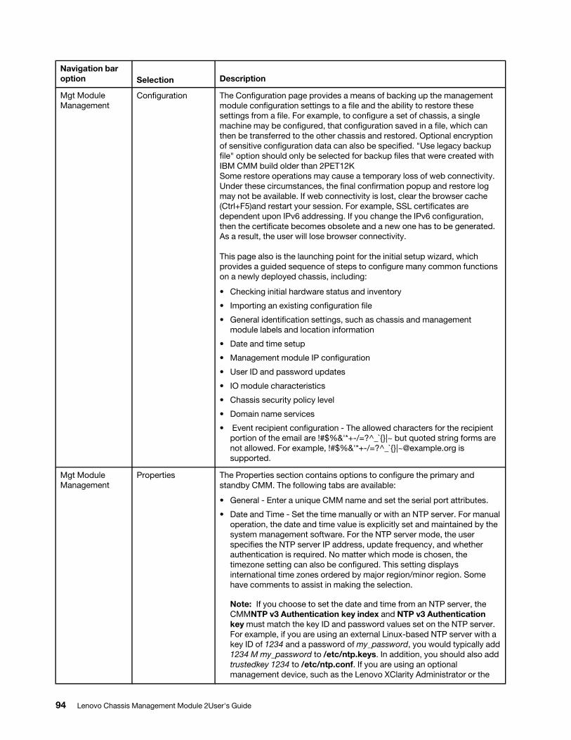
Navigation bar option Selection Description
Mgt Module Management
Configuration The Configuration page provides a means of backing up the management module configuration settings to a file and the ability to restore these settings from a file. For example, to configure a set of chassis, a single machine may be configured, that configuration saved in a file, which can then be transferred to the other chassis and restored. Optional encryption of sensitive configuration data can also be specified. "Use legacy backup file" option should only be selected for backup files that were created with IBM CMM build older than 2PET12K Some restore operations may cause a temporary loss of web connectivity. Under these circumstances, the final confirmation popup and restore log may not be available. If web connectivity is lost, clear the browser cache (Ctrl+F5)and restart your session. For example, SSL certificates are dependent upon IPv6 addressing. If you change the IPv6 configuration, then the certificate becomes obsolete and a new one has to be generated. As a result, the user will lose browser connectivity.
This page also is the launching point for the initial setup wizard, which provides a guided sequence of steps to configure many common functions on a newly deployed chassis, including:
• Checking initial hardware status and inventory
• Importing an existing configuration file
• General identification settings, such as chassis and management module labels and location information
• Date and time setup
• Management module IP configuration
• User ID and password updates
• IO module characteristics
• Chassis security policy level
• Domain name services
• Event recipient configuration - The allowed characters for the recipient portion of the email are !#$%&'*+-/=?^_`{}|~ but quoted string forms are not allowed. For example, !#$%&'*+-/=?^_`{}|[email protected] is supported.
Mgt Module Management
Properties The Properties section contains options to configure the primary and standby CMM. The following tabs are available:
• General - Enter a unique CMM name and set the serial port attributes.
• Date and Time - Set the time manually or with an NTP server. For manual operation, the date and time value is explicitly set and maintained by the system management software. For the NTP server mode, the user specifies the NTP server IP address, update frequency, and whether authentication is required. No matter which mode is chosen, the timezone setting can also be configured. This setting displays international time zones ordered by major region/minor region. Some have comments to assist in making the selection.
Note: If you choose to set the date and time from an NTP server, the CMMNTP v3 Authentication key index and NTP v3 Authentication key must match the key ID and password values set on the NTP server. For example, if you are using an external Linux-based NTP server with a key ID of 1234 and a password of my_password, you would typically add 1234 M my_password to /etc/ntp.keys. In addition, you should also add trustedkey 1234 to /etc/ntp.conf. If you are using an optional management device, such as the Lenovo XClarity Administrator or the
94 Lenovo Chassis Management Module 2User's Guide
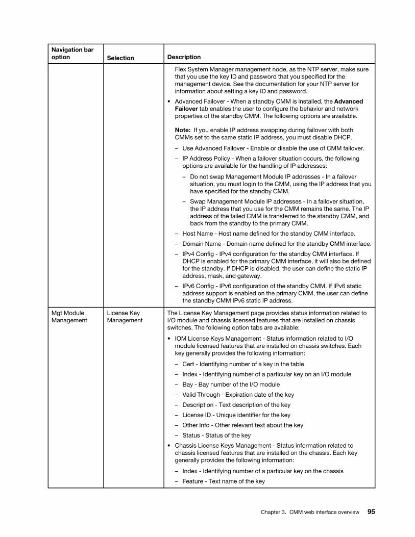
Navigation bar option Selection Description
Flex System Manager management node, as the NTP server, make sure that you use the key ID and password that you specified for the management device. See the documentation for your NTP server for information about setting a key ID and password.
• Advanced Failover - When a standby CMM is installed, the Advanced Failover tab enables the user to configure the behavior and network properties of the standby CMM. The following options are available.
Note: If you enable IP address swapping during failover with both CMMs set to the same static IP address, you must disable DHCP.
– Use Advanced Failover - Enable or disable the use of CMM failover.
– IP Address Policy - When a failover situation occurs, the following options are available for the handling of IP addresses:
– Do not swap Management Module IP addresses - In a failover situation, you must login to the CMM, using the IP address that you have specified for the standby CMM.
– Swap Management Module IP addresses - In a failover situation, the IP address that you use for the CMM remains the same. The IP address of the failed CMM is transferred to the standby CMM, and back from the standby to the primary CMM.
– Host Name - Host name defined for the standby CMM interface.
– Domain Name - Domain name defined for the standby CMM interface.
– IPv4 Config - IPv4 configuration for the standby CMM interface. If DHCP is enabled for the primary CMM interface, it will also be defined for the standby. If DHCP is disabled, the user can define the static IP address, mask, and gateway.
– IPv6 Config - IPv6 configuration of the standby CMM. If IPv6 static address support is enabled on the primary CMM, the user can define the standby CMM IPv6 static IP address.
Mgt Module Management
License Key Management
The License Key Management page provides status information related to I/O module and chassis licensed features that are installed on chassis switches. The following option tabs are available:
• IOM License Keys Management - Status information related to I/O module licensed features that are installed on chassis switches. Each key generally provides the following information:
– Cert - Identifying number of a key in the table
– Index - Identifying number of a particular key on an I/O module
– Bay - Bay number of the I/O module
– Valid Through - Expiration date of the key
– Description - Text description of the key
– License ID - Unique identifier for the key
– Other Info - Other relevant text about the key
– Status - Status of the key
• Chassis License Keys Management - Status information related to chassis licensed features that are installed on the chassis. Each key generally provides the following information:
– Index - Identifying number of a particular key on the chassis
– Feature - Text name of the key
Chapter 3. CMM web interface overview 95
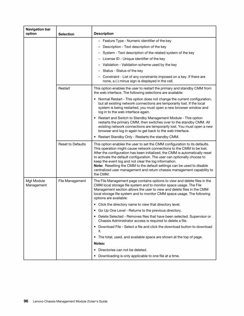
Navigation bar option Selection Description
– Feature Type - Numeric identifier of the key
– Description - Text description of the key
– System - Text description of the related system of the key
– License ID - Unique identifier of the key
– Validation - Validation scheme used by the key
– Status - Status of the key
– Constraint - List of any constraints imposed on a key. If there are none, a (-) minus sign is displayed in the cell.
Restart This option enables the user to restart the primary and standby CMM from the web interface. The following selections are available:
• Normal Restart - This option does not change the current configuration, but all existing network connections are temporarily lost. If the local system is being restarted, you must open a new browser window and log in to the web interface again.
• Restart and Switch to Standby Management Module - This option restarts the primary CMM, then switches over to the standby CMM. All existing network connections are temporarily lost. You must open a new browser and log in again to get back to the web interface.
• Restart Standby Only - Restarts the standby CMM.
Reset to Defaults This option enables the user to set the CMM configuration to its defaults. This operation might cause network connections to the CMM to be lost. After the configuration has been initialized, the CMM is automatically reset to activate the default configuration. The user can optionally choose to keep the event log and not clear the log information. Note: Resetting the CMM to the default settings can be used to disable centralized user management and return chassis management capability to the CMM.
Mgt Module Management
File Management The File Management page contains options to view and delete files in the CMM local storage file system and to monitor space usage. The File Management section allows the user to view and delete files in the CMM local storage file system and to monitor CMM space usage. The following options are available:
• Click the directory name to view that directory level.
• Go Up One Level - Returns to the previous directory.
• Delete Selected - Removes files that have been selected. Supervisor or Chassis Administrator access is required to delete a file.
• Download File - Select a file and click the download button to download it.
• The total, used, and available space are shown at the top of page.
Notes:
• Directories can not be deleted.
• Downloading is only applicable to one file at a time.
96 Lenovo Chassis Management Module 2User's Guide
Appendix A. Getting help and technical assistance
If you need help, service, or technical assistance or just want more information about Lenovo products, you will find a wide variety of sources available from Lenovo to assist you.
Use this information to obtain additional information about Lenovo and Lenovo products, and determine what to do if you experience a problem with your Lenovo system or optional device.
Note: This section includes references to IBM web sites and information about obtaining service. IBM is Lenovo's preferred service provider for the System x, Flex System, and NeXtScale System products.
Before you callBefore you call, make sure that you have taken these steps to try to solve the problem yourself.
If you believe that you require warranty service for your Lenovo product, the service technicians will be able to assist you more efficiently if you prepare before you call.
• Check all cables to make sure that they are connected.
• Check the power switches to make sure that the system and any optional devices are turned on.
• Check for updated software, firmware, and operating-system device drivers for your Lenovo product. The Lenovo Warranty terms and conditions state that you, the owner of the Lenovo product, are responsible for maintaining and updating all software and firmware for the product (unless it is covered by an additional maintenance contract). Your service technician will request that you upgrade your software and firmware if the problem has a documented solution within a software upgrade.
• If you have installed new hardware or software in your environment, check http://static.lenovo.com/us/en/ serverproven/index.shtml to make sure that the hardware and software is supported by your product.
• Go to http://datacentersupport.lenovo.com to check for information to help you solve the problem.
• Gather the following information to provide to the service technician. This data will help the service technician quickly provide a solution to your problem and ensure that you receive the level of service for which you might have contracted.
– Hardware and Software Maintenance agreement contract numbers, if applicable
– Machine type number (Lenovo 4-digit machine identifier)
– Model number
– Serial number
– Current system UEFI and firmware levels
– Other pertinent information such as error messages and logs
• Go to http://www.ibm.com/support/entry/portal/Open_service_request to submit an Electronic Service Request. Submitting an Electronic Service Request will start the process of determining a solution to your problem by making the pertinent information available to the service technicians. The IBM service technicians can start working on your solution as soon as you have completed and submitted an Electronic Service Request.
You can solve many problems without outside assistance by following the troubleshooting procedures that Lenovo provides in the online help or in the Lenovo product documentation. The Lenovo product documentation also describes the diagnostic tests that you can perform. The documentation for most systems, operating systems, and programs contains troubleshooting procedures and explanations of error messages and error codes. If you suspect a software problem, see the documentation for the operating system or program.
© Copyright Lenovo 2016, 2020 97
Using the documentationInformation about your Lenovo system and preinstalled software, if any, or optional device is available in the product documentation. That documentation can include printed documents, online documents, readme files, and help files.
See the troubleshooting information in your system documentation for instructions for using the diagnostic programs. The troubleshooting information or the diagnostic programs might tell you that you need additional or updated device drivers or other software. Lenovo maintains pages on the World Wide Web where you can get the latest technical information and download device drivers and updates. To access these pages, go to http://datacentersupport.lenovo.com.
Getting help and information from the World Wide WebUp-to-date information about Lenovo products and support is available on the World Wide Web.
On the World Wide Web, up-to-date information about Lenovo systems, optional devices, services, and support is available at http://datacentersupport.lenovo.com. The most current version of the product documentation is available in the following product-specific Information Centers:
Flex System products: http://flexsystem.lenovofiles.com/help/index.jsp
System x products: http://systemx.lenovofiles.com/help/index.jsp
NeXtScale System products: http://nextscale.lenovofiles.com/help/index.jsp
How to send service dataYou can use the Enhanced Customer Data Repository to send diagnostic data.
Before you send diagnostic data, read the terms of use at http://www.ibm.com/de/support/ecurep/terms.html.
You can use any of the following methods to send diagnostic data:
• Standard upload: http://www.ibm.com/de/support/ecurep/send_http.html
• Standard upload with the system serial number: http://www.ecurep.ibm.com/app/upload_hw
• Secure upload: http://www.ibm.com/de/support/ecurep/send_http.html#secure
• Secure upload with the system serial number: https://www.ecurep.ibm.com/app/upload_hw
Creating a personalized support web pageYou can create a personalized support web page by identifying Lenovo products that are of interest to you.
To create a personalized support web page, go to https://support.lenovo.com. From this personalized page, you can subscribe to weekly email notifications about new technical documents, search for information and downloads, and access various administrative services.
Software service and supportThrough IBM Support Line, you can get telephone assistance, for a fee, with usage, configuration, and software problems with your Lenovo products.
For more information about Support Line and other IBM services, see http://www.ibm.com/services or see http://www.ibm.com/planetwide for support telephone numbers. In the U.S. and Canada, call 1-800-IBM- SERV (1-800-426-7378).
98 Lenovo Chassis Management Module 2User's Guide
Hardware service and supportIBM is Lenovo's preferred service provider for the System x, Flex System and NeXtScale System products.
You can receive hardware service through your Lenovo reseller or from IBM. To locate a reseller authorized by Lenovo to provide warranty service, go to http://www.ibm.com/partnerworld and click Business Partner Locator. For IBM support telephone numbers, see http://www.ibm.com/planetwide. In the U.S. and Canada, call 1-800-IBM-SERV (1-800-426-7378).
In the U.S. and Canada, hardware service and support is available 24 hours a day, 7 days a week. In the U. K., these services are available Monday through Friday, from 9 a.m. to 6 p.m.
Taiwan product serviceUse this information to contact product service for Taiwan.
Appendix A. Getting help and technical assistance 99

100 Lenovo Chassis Management Module 2User's Guide
Appendix B. Notices
Lenovo may not offer the products, services, or features discussed in this document in all countries. Consult your local Lenovo representative for information on the products and services currently available in your area.
Any reference to a Lenovo product, program, or service is not intended to state or imply that only that Lenovo product, program, or service may be used. Any functionally equivalent product, program, or service that does not infringe any Lenovo intellectual property right may be used instead. However, it is the user's responsibility to evaluate and verify the operation of any other product, program, or service.
Lenovo may have patents or pending patent applications covering subject matter described in this document. The furnishing of this document does not give you any license to these patents. You can send license inquiries, in writing, to:
Lenovo (United States), Inc. 1009 Think Place - Building OneMorrisville, NC 27560U.S.A.Attention: Lenovo Director of Licensing
LENOVO PROVIDES THIS PUBLICATION “AS IS” WITHOUT WARRANTY OF ANY KIND, EITHER EXPRESS OR IMPLIED, INCLUDING, BUT NOT LIMITED TO, THE IMPLIED WARRANTIES OF NON-INFRINGEMENT, MERCHANTABILITY OR FITNESS FOR A PARTICULAR PURPOSE. Some jurisdictions do not allow disclaimer of express or implied warranties in certain transactions, therefore, this statement may not apply to you.
This information could include technical inaccuracies or typographical errors. Changes are periodically made to the information herein; these changes will be incorporated in new editions of the publication. Lenovo may make improvements and/or changes in the product(s) and/or the program(s) described in this publication at any time without notice.
The products described in this document are not intended for use in implantation or other life support applications where malfunction may result in injury or death to persons. The information contained in this document does not affect or change Lenovo product specifications or warranties. Nothing in this document shall operate as an express or implied license or indemnity under the intellectual property rights of Lenovo or third parties. All information contained in this document was obtained in specific environments and is presented as an illustration. The result obtained in other operating environments may vary.
Lenovo may use or distribute any of the information you supply in any way it believes appropriate without incurring any obligation to you.
Any references in this publication to non-Lenovo Web sites are provided for convenience only and do not in any manner serve as an endorsement of those Web sites. The materials at those Web sites are not part of the materials for this Lenovo product, and use of those Web sites is at your own risk.
Any performance data contained herein was determined in a controlled environment. Therefore, the result obtained in other operating environments may vary significantly. Some measurements may have been made on development-level systems and there is no guarantee that these measurements will be the same on generally available systems. Furthermore, some measurements may have been estimated through extrapolation. Actual results may vary. Users of this document should verify the applicable data for their specific environment.
© Copyright Lenovo 2016, 2020 101
TrademarksLenovo, the Lenovo logo, Flex System, System x, NeXtScale System, and x Architecture are trademarks of Lenovo in the United States, other countries, or both.
Intel and Intel Xeon are trademarks of Intel Corporation in the United States, other countries, or both.
Internet Explorer, Microsoft, and Windows are trademarks of the Microsoft group of companies.
Linux is a registered trademark of Linus Torvalds.
Other company, product, or service names may be trademarks or service marks of others.
Important notesProcessor speed indicates the internal clock speed of the microprocessor; other factors also affect application performance.
CD or DVD drive speed is the variable read rate. Actual speeds vary and are often less than the possible maximum.
When referring to processor storage, real and virtual storage, or channel volume, KB stands for 1 024 bytes, MB stands for 1 048 576 bytes, and GB stands for 1 073 741 824 bytes.
When referring to hard disk drive capacity or communications volume, MB stands for 1 000 000 bytes, and GB stands for 1 000 000 000 bytes. Total user-accessible capacity can vary depending on operating environments.
Maximum internal hard disk drive capacities assume the replacement of any standard hard disk drives and population of all hard-disk-drive bays with the largest currently supported drives that are available from Lenovo.
Maximum memory might require replacement of the standard memory with an optional memory module.
Each solid-state memory cell has an intrinsic, finite number of write cycles that the cell can incur. Therefore, a solid-state device has a maximum number of write cycles that it can be subjected to, expressed as total bytes written (TBW). A device that has exceeded this limit might fail to respond to system-generated commands or might be incapable of being written to. Lenovo is not responsible for replacement of a device that has exceeded its maximum guaranteed number of program/erase cycles, as documented in the Official Published Specifications for the device.
Lenovo makes no representations or warranties with respect to non-Lenovo products. Support (if any) for the non-Lenovo products is provided by the third party, not Lenovo.
Some software might differ from its retail version (if available) and might not include user manuals or all program functionality.
Recycling informationLenovo encourages owners of information technology (IT) equipment to responsibly recycle their equipment when it is no longer needed. Lenovo offers a variety of programs and services to assist equipment owners in recycling their IT products. For information on recycling Lenovo products, go to: http://www.lenovo.com/ recycling.
102 Lenovo Chassis Management Module 2User's Guide
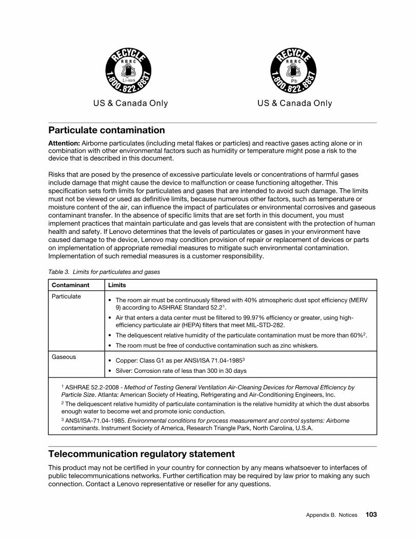
Particulate contaminationAttention: Airborne particulates (including metal flakes or particles) and reactive gases acting alone or in combination with other environmental factors such as humidity or temperature might pose a risk to the device that is described in this document.
Risks that are posed by the presence of excessive particulate levels or concentrations of harmful gases include damage that might cause the device to malfunction or cease functioning altogether. This specification sets forth limits for particulates and gases that are intended to avoid such damage. The limits must not be viewed or used as definitive limits, because numerous other factors, such as temperature or moisture content of the air, can influence the impact of particulates or environmental corrosives and gaseous contaminant transfer. In the absence of specific limits that are set forth in this document, you must implement practices that maintain particulate and gas levels that are consistent with the protection of human health and safety. If Lenovo determines that the levels of particulates or gases in your environment have caused damage to the device, Lenovo may condition provision of repair or replacement of devices or parts on implementation of appropriate remedial measures to mitigate such environmental contamination. Implementation of such remedial measures is a customer responsibility.
Table 3. Limits for particulates and gases
Contaminant Limits
Particulate• The room air must be continuously filtered with 40% atmospheric dust spot efficiency (MERV
9) according to ASHRAE Standard 52.21.
• Air that enters a data center must be filtered to 99.97% efficiency or greater, using high- efficiency particulate air (HEPA) filters that meet MIL-STD-282.
• The deliquescent relative humidity of the particulate contamination must be more than 60%2.
• The room must be free of conductive contamination such as zinc whiskers.
Gaseous • Copper: Class G1 as per ANSI/ISA 71.04-19853
• Silver: Corrosion rate of less than 300 in 30 days
1 ASHRAE 52.2-2008 - Method of Testing General Ventilation Air-Cleaning Devices for Removal Efficiency by Particle Size. Atlanta: American Society of Heating, Refrigerating and Air-Conditioning Engineers, Inc.2 The deliquescent relative humidity of particulate contamination is the relative humidity at which the dust absorbs enough water to become wet and promote ionic conduction.3 ANSI/ISA-71.04-1985. Environmental conditions for process measurement and control systems: Airborne contaminants. Instrument Society of America, Research Triangle Park, North Carolina, U.S.A.
Telecommunication regulatory statementThis product may not be certified in your country for connection by any means whatsoever to interfaces of public telecommunications networks. Further certification may be required by law prior to making any such connection. Contact a Lenovo representative or reseller for any questions.
Appendix B. Notices 103
Electronic emission noticesWhen you attach a monitor to the equipment, you must use the designated monitor cable and any interference suppression devices that are supplied with the monitor.
Federal Communications Commission (FCC) statementNote: This equipment has been tested and found to comply with the limits for a Class A digital device, pursuant to Part 15 of the FCC Rules. These limits are designed to provide reasonable protection against harmful interference when the equipment is operated in a commercial environment. This equipment generates, uses, and can radiate radio frequency energy and, if not installed and used in accordance with the instruction manual, may cause harmful interference to radio communications. Operation of this equipment in a residential area is likely to cause harmful interference, in which case the user will be required to correct the interference at his own expense.
Properly shielded and grounded cables and connectors must be used in order to meet FCC emission limits. Lenovo is not responsible for any radio or television interference caused by using other than recommended cables and connectors or by unauthorized changes or modifications to this equipment. Unauthorized changes or modifications could void the user's authority to operate the equipment.
This device complies with Part 15 of the FCC Rules. Operation is subject to the following two conditions: (1) this device may not cause harmful interference, and (2) this device must accept any interference received, including interference that might cause undesired operation.
Industry Canada Class A emission compliance statementThis Class A digital apparatus complies with Canadian ICES-003.
Avis de conformité à la réglementation d'Industrie CanadaCet appareil numérique de la classe A est conforme à la norme NMB-003 du Canada.
Australia and New Zealand Class A statementAttention: This is a Class A product. In a domestic environment this product may cause radio interference in which case the user may be required to take adequate measures.
European Union EMC Directive conformance statementThis product is in conformity with the protection requirements of EU Council Directive 2014/30/EU on the approximation of the laws of the Member States relating to electromagnetic compatibility. Lenovo cannot accept responsibility for any failure to satisfy the protection requirements resulting from a non-recommended modification of the product, including the installation of option cards from other manufacturers.
This product has been tested and found to comply with the limits for Class A equipment according to European Standards harmonized in the Directives in compliance. The limits for Class A equipment were derived for commercial and industrial environments to provide reasonable protection against interference with licensed communication equipment.
Lenovo, Einsteinova 21, 851 01 Bratislava, Slovakia
Warning: This is a Class A product. In a domestic environment this product may cause radio interference in which case the user may be required to take adequate measures.
104 Lenovo Chassis Management Module 2User's Guide
Germany Class A statementDeutschsprachiger EU Hinweis: Hinweis für Geräte der Klasse A EU-Richtlinie zur Elektromagnetischen Verträglichkeit
Deutschsprachiger EU Hinweis:Hinweis für Geräte der Klasse A EU-Richtlinie zur Elektromagnetischen Verträglichkeit Dieses Produkt entspricht den Schutzanforderungen der EU- Richtlinie 2014/30/EU (früher 2004/108/EC) zur Angleichung der Rechtsvorschriften über die elektromagnetische Verträglichkeit in den EU-Mitgliedsstaaten und hält die Grenzwerte der Klasse A der Norm gemäß Richtlinie.
Um dieses sicherzustellen, sind die Geräte wie in den Handbüchern beschrieben zu installieren und zu betreiben. Des Weiteren dürfen auch nur von der Lenovo empfohlene Kabel angeschlossen werden. Lenovo übernimmt keine Verantwortung für die Einhaltung der Schutzanforderungen, wenn das Produkt ohne Zustimmung der Lenovo verändert bzw. wenn Erweiterungskomponenten von Fremdherstellern ohne Empfehlung der Lenovo gesteckt/eingebaut werden.
Deutschland:
Einhaltung des Gesetzes über die elektromagnetische Verträglichkeit von Betriebsmittein Dieses Produkt entspricht dem „Gesetz über die elektromagnetische Verträglichkeit von Betriebsmitteln“ EMVG (früher „Gesetz über die elektromagnetische Verträglichkeit von Geräten“). Dies ist die Umsetzung der EU- Richtlinie 2014/30/EU (früher 2004/108/EC) in der Bundesrepublik Deutschland.
Zulassungsbescheinigung laut dem Deutschen Gesetz über die elektromagnetische Verträglichkeit von Betriebsmitteln, EMVG vom 20. Juli 2007 (früher Gesetz über die elektromagnetische Verträglichkeit von Geräten), bzw. der EMV EU Richtlinie 2014/30/EU (früher 2004/108/EC), für Geräte der Klasse A.
Dieses Gerät ist berechtigt, in Übereinstimmung mit dem Deutschen EMVG das EG-Konformitätszeichen - CE - zu führen. Verantwortlich für die Konformitätserklärung nach Paragraf 5 des EMVG ist die Lenovo (Deutschland) GmbH, Meitnerstr. 9, D-70563 Stuttgart.
Informationen in Hinsicht EMVG Paragraf 4 Abs. (1) 4:Das Gerät erfüllt die Schutzanforderungen nach EN 55024 und EN 55022 Klasse A.
Nach der EN 55022: „Dies ist eine Einrichtung der Klasse A. Diese Einrichtung kann im Wohnbereich Funkstörungen verursachen; in diesem Fall kann vom Betreiber verlangt werden, angemessene Maßnahmen durchzuführen und dafür aufzukommen.“
Nach dem EMVG: „Geräte dürfen an Orten, für die sie nicht ausreichend entstört sind, nur mit besonderer Genehmigung des Bundesministers für Post und Telekommunikation oder des Bundesamtes für Post und Telekommunikation betrieben werden. Die Genehmigung wird erteilt, wenn keine elektromagnetischen Störungen zu erwarten sind.“ (Auszug aus dem EMVG, Paragraph 3, Abs. 4). Dieses Genehmigungsverfahren ist nach Paragraph 9 EMVG in Verbindung mit der entsprechenden Kostenverordnung (Amtsblatt 14/93) kostenpflichtig.
Anmerkung: Um die Einhaltung des EMVG sicherzustellen sind die Geräte, wie in den Handbüchern angegeben, zu installieren und zu betreiben.
Appendix B. Notices 105
Japanese electromagnetic compatibility statements
Japan VCCI Class A statement
This is a Class A product based on the standard of the Voluntary Control Council for Interference (VCCI). If this equipment is used in a domestic environment, radio interference may occur, in which case the user may be required to take corrective actions.
Japanese Electrical Appliance and Material Safety Law statement (for detachable AC power cord)
JEITA harmonics guideline - Japanese Statement for AC power consumption (W)
Korea Communications Commission (KCC) statement
This is electromagnetic wave compatibility equipment for business (Type A). Sellers and users need to pay attention to it. This is for any areas other than home.
Russia Electromagnetic Interference (EMI) Class A statement
106 Lenovo Chassis Management Module 2User's Guide
People's Republic of China Class A electronic emission statement
Taiwan Class A compliance statement
Appendix B. Notices 107
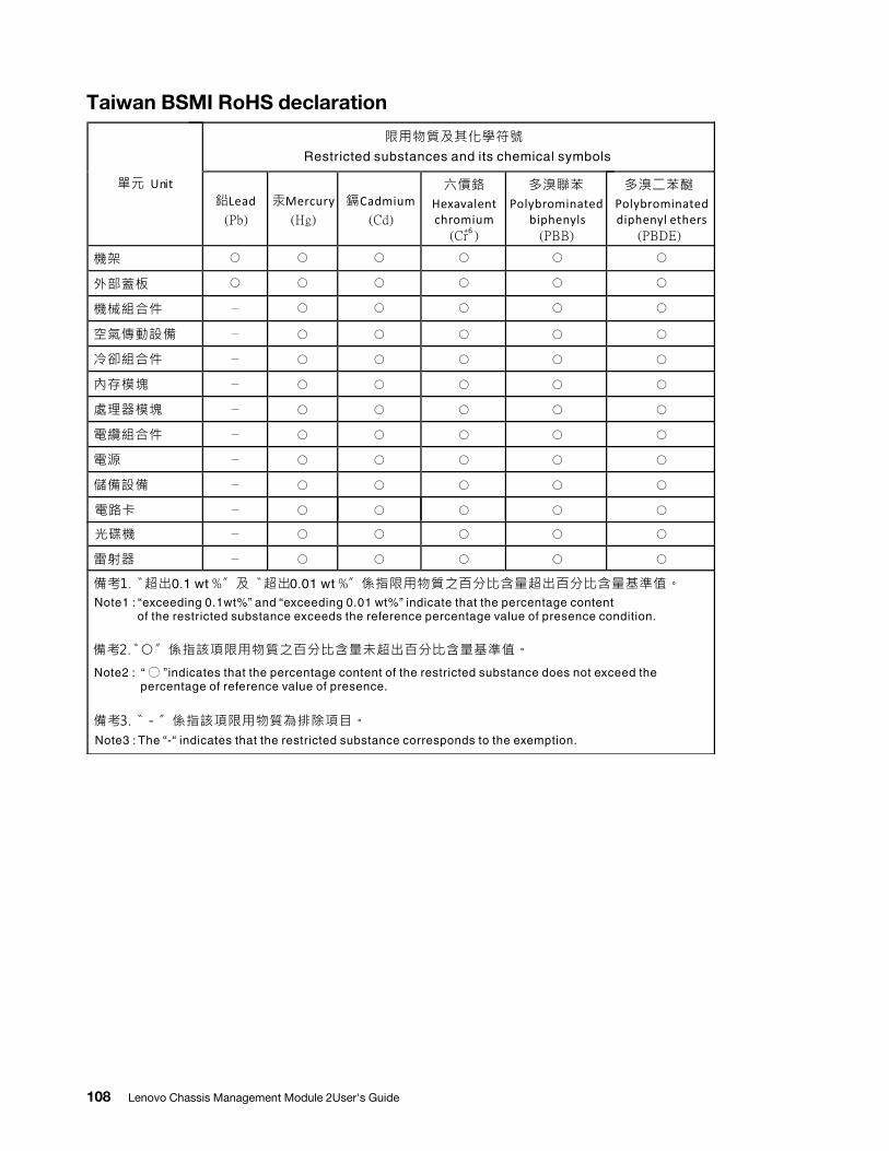
Taiwan BSMI RoHS declaration
108 Lenovo Chassis Management Module 2User's Guide
Index
Aaccessibility features for the CMM 2active events 46air filter 64air flow 64airflow 64assistance, getting 97Attention notice, meaning 2Australia Class A statement 104authentication (mutual) of CSR import
using web interface 22authentication (non-mutual) of LDAP certificate import
using web interface 21authentication of CA
using CLI 18using web interface 18
authentication of certificate using CLI 18using web interface 18
authentication of CSR using CLI 18using web interface 18
Bbackup CMM configuration 35backup firmware status 60bist 60booting from standby 39built in self test 60built-in self test 60
CCA authentication
using CLI 18using web interface 18
CA import (mutual authentication) using web interface 22
CA import (non-mutual authentication) using web interface 21
Canada Class A electronic emission statement 104Caution notice, meaning 2centralized user account management
disable 95centralized user management 29certificate authentication
using CLI 18using web interface 18
certificate import (mutual authentication) using web interface 22
certificate import (non-mutual authentication) using web interface 21
change chassis name 46chassis airflow 64chassis global settings 65chassis graphical view 46chassis identification 64chassis LED 64chassis LEDs 64chassis management 62chassis management menu 62Chassis Management Module 2
ports 39chassis management module web interface
starting 43chassis name 46chassis table view 46China Class A electronic emission statement 107CIM https port 39Class A electronic emission notice 104CLI
CA authentication 18certificate authentication 18CSR authentication 18
CMM active events 46air filter 24authority, use 29authority, user 43backup configuration 35backup firmware status 60bist 60booting from standby 39built in self test 60built-in self test 60chassis graphical view 46chassis management 62chassis management menu 62chassis management module web interface 46chassis table view 46configure 5, 23configure components 23configure storage node 25connectivity list 60control enclosure 25cryptography 88cryptography options 88cryptography setting 88default setting 17download service data 55, 60email event recipients 54email events 54email recipients 54enable floating ip address 39enable service and support 59enable support 59enclosure 25event id 54event log 53event log information 53event recipient 33event recipients 53–54event sequence number 54event severity 54, 59event source 54events 33, 50, 53filter 24floating ip address 39general 50graphical interface 46graphical user interface 46graphical view 46, 50graphical view, chassis 46GUI 46hard restart 55, 60health 60ignored service problems 59information, system 46interface, graphical 46interface, graphical user 46ip address 39managing multiple chassis 52manufacturing defaults 17
© Copyright Lenovo 2016, 2020 109
monitor events 33multiple chassis 52multiple chassis monitor 52networked chassis 52NIST 88NIST compliance 88node 25problem ticket number 59redundancy failure 39redundant 39reset 39, 55, 60reset to default 17restore backup 36restore backup configuration 36restore configuration 36save configuration 35saving backup configuration 35saving configuration 35service 55service and support settings 59service contact 59service data 55, 60service data file 60service events 54service level reset 55service reset 55, 60service ticket number 59service-level reset 55serviceable events 54serviceable problems 59snmp event 54snmp event recipients 54snmp recipients 54ssl 88ssl setting 88standby 39starting the chassis management module web interface 46starting web interface 46status, system 46, 50support 55syslog event recipients 54syslog recipients 54system information 46system status 46, 50table view 46, 50table view, chassis 46tls 88tls setting 88troubleshooting 55, 59UI 1, 46user account 29user authority 29, 43user authority required 29user interface 1user interface introduction 1user interface, graphical 46user roles 29, 43view, chassis graphical 46view, chassis table 46view, graphical 46virtual re-seat 55, 60virtual reseat 55, 60web interface pages
user authority required 43web user interface 1
CMM manage storage 69compute node
remote access 34remote console 34remote session 34
compute node service data 61connectivity list 60contamination, particulate and gaseous 103creating a personalized support web page 98CSR authentication
using CLI 18using web interface 18
CSR import (mutual authentication) using web interface 22
custom support web page 98
DDanger notice, meaning 2DHCP (UDP) port 39disable centralized user account management
disable 95disable centralized user management 29DNS resolver (UDP) port 39documentation
using 98download service data 55, 60DSA, sending data 98
Eelectronic emission Class A notice 104email alerts (TCP) port 39enable service and support 59enable support 59European Union EMC Directive conformance statement 104event id 54event log 53event log information 53event recipients 53–54event sequence number 54event severity 54, 59event source 54events 50, 53
FFCC Class A notice 104fixed
ports 39fixed ports 39FTP data port 39FTP port 39
Ggaseous contamination 103general 50Germany Class A statement 105global settings 65graphical interface 46graphical user interface 46graphical view 46, 50graphical view, chassis 46GUI 46
Hhard restart 55, 60hardware service and support telephone numbers 99help
from the World Wide Web 98from World Wide Web 98sending diagnostic data 98sources of 97
http port 39https (CIM) port 39
110 Lenovo Chassis Management Module 2User's Guide
https (XML) port 39https port 39
Iignored service problems 59IMM
firmware 26login 34, 62remote access 26remote console 26remote session 26
import (mutual authentication) of CA using web interface 22
import (non-mutual authentication) of CA using web interface 21
Important notice, meaning 2important notices 102information center 98information, system 46interface, graphical 46interface, graphical user 46IO modulestacking
events 71launch 71ping 71power 71reset defaults 71restart 71
IPMI 29
JJapanese electromagnetic compatibility statements 106
KKorea Class A electronic emission statement 106
LLDAP (secure) port 39LDAP certificate import (non-mutual authentication)
using web interface 21LDAP port 39Lenovo Chassis Management Module 2
managing power 16power management 16power redundancy 16redundant power policy 16
login 62 IMM 62
Mmanage compute nodes 65manage nodes 65manage servers 65manage storage 69managing multiple chassis 52monitoring networked chassis 52multiple chassis 52multiple chassis monitor 52mutual authentication certificate import
using web interface 22mutual authentication import of CA
using web interface 22
mutual authentication import of CSR using web interface 22
NNew Zealand Class A statement 104non-mutual authentication certificate import
using web interface 21non-mutual authentication import of CA
using web interface 21non-mutual authentication import of LDAP certificate
using web interface 21notes, important 102notices 101
electronic emission 104FCC, Class A 104
NTP port 39
Pparticulate contamination 103People's Republic of China Class A electronic emission
statement 107ports
Chassis Management Module 2 39CIM https 39DHCP (UDP) 39DNS resolver (UDP) 39email alerts (TCP) 39FTP 39FTP data 39http 39https 39https (CIM) 39https (XML) 39LDAP 39LDAP (secure) 39NTP 39RMCP 39secure LDAP 39secure TCP command mode 39SLP 39SNMP agent 39SNMP traps 39SNMPv3 traps 39SSH 39TCP command mode 39TCP command mode (secure) 39telnet 39TFTP 39XML https 39
power on 65problem ticket number 59product service, Taiwan 99Provision IPMI 29Provision SNMPv3 29
Rredundancy failure 39redundant 39requirements
CMM software, web interface 3reset 39, 55, 60reset to defaults 95restart 65RMCP port 39Russia Class A electronic emission statement 106
© Copyright Lenovo 2016, 2020 111
Ssave CMM configuration 35saving backup configuration 35saving CMM configuration 35secure LDAP port 39secure TCP command mode port 39sending diagnostic data 98service 55service and support
before you call 97hardware 99software 98
service and support settings 59service contact 59service data 55, 60–61service data file 60service events 54service level reset 55service reset 55, 60service ticket number 59service-level reset 55serviceable events 54serviceable problems 59setup 6setup wizard 6SLP port 39SNMP agent port 39SNMP traps port 39SNMPv3 29SNMPv3 traps port 39software
requirements, CMM web interface 3software service and support telephone numbers 98SSH port 39standby 39starting the chassis management module web interface 43status, system 46, 50storage node 69storage node restart 69storage node service data 61storage power restart 69support 55support web page, custom 98system information 46system information quick view 46system status 46, 50
Ttable view 46, 50table view, chassis 46Taiwan BSMI RoHS declaration 108
Taiwan Class A electronic emission statement 107Taiwan product service 99TCP command mode (secure) port 39TCP command mode port 39telecommunication regulatory statement 103telephone numbers 98–99telnet port 39TFTP port 39trademarks 102troubleshooting 55, 59
UUI 1, 46United States FCC Class A notice 104user configurable
ports 39user configurable ports 39user interface 1user interface introduction 1user interface, graphical 46
Vview, chassis graphical 46view, chassis table 46view, graphical 46virtual re-seat 55, 60virtual reseat 55, 60
Wweb interface 5
CA authentication 18CA mutual authentication import 22CA non-mutual authentication import 21certificate authentication 18CSR authentication 18CSR import (mutual authentication) 22LDAP certificate import (non-mutual authentication) 21mutual authentication certificate import 22non-mutual authentication certificate import 21
web user interface 1wizard 6
XXML https port 39
112 Lenovo Chassis Management Module 2User's Guide

Part Number: SP47A31781
Printed in China
(1P) P/N: SP47A31781
*1PSP47A31781*