Embed Size (px)
Citation preview
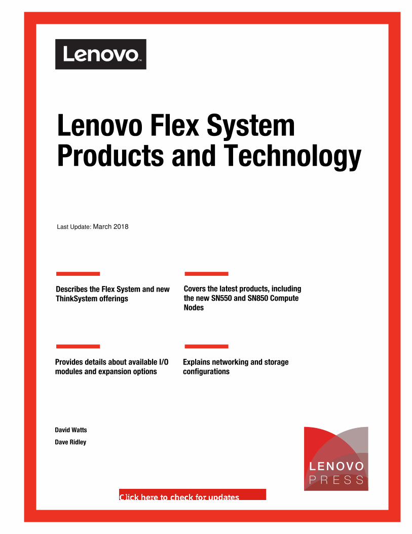
Last Update: March 2018
Front cover
Lenovo Flex System Products and Technology
Describes the Flex System and new ThinkSystem offerings
Covers the latest products, including the new SN550 and SN850 Compute Nodes
Provides details about available I/O modules and expansion options
Explains networking and storage configurations
David Watts
Dave Ridley


Lenovo Flex System Products and Technology
March 2018
SG24-8255-01

© Copyright Lenovo 2018. All rights reserved.Note to U.S. Government Users Restricted Rights -- Use, duplication or disclosure restricted by GSA ADP Schedule Contract
Last update on March 2018
This edition applies to:
� Lenovo Flex System Enterprise Chassis, 8721� Lenovo Flex System Carrier-Grade Chassis, 7385� Lenovo ThinkSystem SN550, 7X16� Lenovo ThinkSystem SN850, 7X15� Lenovo Flex System x240 M5 Compute Node (E5-2600 v4), 9532
Note: Before using this information and the product it supports, read the information in “Notices” on page ix.
Contents
Notices . . . . . . . . . . . . . . . . . . . . . . . . . . . . . . . . . . . . . . . . . . . . . . . . . . . . . . . . . . . . . . . . . ixTrademarks . . . . . . . . . . . . . . . . . . . . . . . . . . . . . . . . . . . . . . . . . . . . . . . . . . . . . . . . . . . . . . .x
Preface . . . . . . . . . . . . . . . . . . . . . . . . . . . . . . . . . . . . . . . . . . . . . . . . . . . . . . . . . . . . . . . . . xiAuthors. . . . . . . . . . . . . . . . . . . . . . . . . . . . . . . . . . . . . . . . . . . . . . . . . . . . . . . . . . . . . . . . . . xiiComments welcome. . . . . . . . . . . . . . . . . . . . . . . . . . . . . . . . . . . . . . . . . . . . . . . . . . . . . . . . xiiDo you have the latest version?. . . . . . . . . . . . . . . . . . . . . . . . . . . . . . . . . . . . . . . . . . . . . . xiii
Summary of changes . . . . . . . . . . . . . . . . . . . . . . . . . . . . . . . . . . . . . . . . . . . . . . . . . . . . . .xv23 March 2018 . . . . . . . . . . . . . . . . . . . . . . . . . . . . . . . . . . . . . . . . . . . . . . . . . . . . . . . . . . . .xv28 February 2017. . . . . . . . . . . . . . . . . . . . . . . . . . . . . . . . . . . . . . . . . . . . . . . . . . . . . . . . . .xv19 January 2017 . . . . . . . . . . . . . . . . . . . . . . . . . . . . . . . . . . . . . . . . . . . . . . . . . . . . . . . . . xvi10 January 2017 . . . . . . . . . . . . . . . . . . . . . . . . . . . . . . . . . . . . . . . . . . . . . . . . . . . . . . . . . xviAugust 2015 . . . . . . . . . . . . . . . . . . . . . . . . . . . . . . . . . . . . . . . . . . . . . . . . . . . . . . . . . . . . . xviiJuly 2015, Second Edition . . . . . . . . . . . . . . . . . . . . . . . . . . . . . . . . . . . . . . . . . . . . . . . . . . xvii3 February 2015. . . . . . . . . . . . . . . . . . . . . . . . . . . . . . . . . . . . . . . . . . . . . . . . . . . . . . . . . . xviiDecember 2014, First Edition. . . . . . . . . . . . . . . . . . . . . . . . . . . . . . . . . . . . . . . . . . . . . . . . xvii
Chapter 1. Introduction. . . . . . . . . . . . . . . . . . . . . . . . . . . . . . . . . . . . . . . . . . . . . . . . . . . . 11.1 Converged Systems for your infrastructure. . . . . . . . . . . . . . . . . . . . . . . . . . . . . . . . . . . 21.2 Flex System overview . . . . . . . . . . . . . . . . . . . . . . . . . . . . . . . . . . . . . . . . . . . . . . . . . . . 2
1.2.1 Lenovo XClarity Administrator. . . . . . . . . . . . . . . . . . . . . . . . . . . . . . . . . . . . . . . . . 21.2.2 Flex System Enterprise Chassis . . . . . . . . . . . . . . . . . . . . . . . . . . . . . . . . . . . . . . . 31.2.3 Flex System Carrier-Grade Chassis . . . . . . . . . . . . . . . . . . . . . . . . . . . . . . . . . . . . 41.2.4 Compute nodes. . . . . . . . . . . . . . . . . . . . . . . . . . . . . . . . . . . . . . . . . . . . . . . . . . . . 51.2.5 PCIe Expansion Node. . . . . . . . . . . . . . . . . . . . . . . . . . . . . . . . . . . . . . . . . . . . . . . 61.2.6 Storage . . . . . . . . . . . . . . . . . . . . . . . . . . . . . . . . . . . . . . . . . . . . . . . . . . . . . . . . . . 61.2.7 I/O modules. . . . . . . . . . . . . . . . . . . . . . . . . . . . . . . . . . . . . . . . . . . . . . . . . . . . . . . 6
1.3 This book. . . . . . . . . . . . . . . . . . . . . . . . . . . . . . . . . . . . . . . . . . . . . . . . . . . . . . . . . . . . . 7
Chapter 2. Systems management . . . . . . . . . . . . . . . . . . . . . . . . . . . . . . . . . . . . . . . . . . . 92.1 Management network . . . . . . . . . . . . . . . . . . . . . . . . . . . . . . . . . . . . . . . . . . . . . . . . . . 102.2 Chassis Management Module. . . . . . . . . . . . . . . . . . . . . . . . . . . . . . . . . . . . . . . . . . . . 13
2.2.1 Overview . . . . . . . . . . . . . . . . . . . . . . . . . . . . . . . . . . . . . . . . . . . . . . . . . . . . . . . . 132.2.2 Interfaces . . . . . . . . . . . . . . . . . . . . . . . . . . . . . . . . . . . . . . . . . . . . . . . . . . . . . . . 15
2.3 Security . . . . . . . . . . . . . . . . . . . . . . . . . . . . . . . . . . . . . . . . . . . . . . . . . . . . . . . . . . . . . 162.4 Compute node management. . . . . . . . . . . . . . . . . . . . . . . . . . . . . . . . . . . . . . . . . . . . . 17
2.4.1 XClarity Controller . . . . . . . . . . . . . . . . . . . . . . . . . . . . . . . . . . . . . . . . . . . . . . . . . 182.4.2 Integrated Management Module II . . . . . . . . . . . . . . . . . . . . . . . . . . . . . . . . . . . . 212.4.3 I/O modules. . . . . . . . . . . . . . . . . . . . . . . . . . . . . . . . . . . . . . . . . . . . . . . . . . . . . . 22
2.5 Lenovo XClarity Administrator. . . . . . . . . . . . . . . . . . . . . . . . . . . . . . . . . . . . . . . . . . . . 232.5.1 Lenovo XClarity Administrator management tasks . . . . . . . . . . . . . . . . . . . . . . . . 242.5.2 Lenovo XClarity Administrator licensing . . . . . . . . . . . . . . . . . . . . . . . . . . . . . . . . 252.5.3 Lenovo XClarity host requirements . . . . . . . . . . . . . . . . . . . . . . . . . . . . . . . . . . . . 272.5.4 Supported managed endpoints . . . . . . . . . . . . . . . . . . . . . . . . . . . . . . . . . . . . . . . 28
Chapter 3. Chassis and infrastructure configuration . . . . . . . . . . . . . . . . . . . . . . . . . . 313.1 Enterprise Chassis . . . . . . . . . . . . . . . . . . . . . . . . . . . . . . . . . . . . . . . . . . . . . . . . . . . . 32
3.1.1 Models . . . . . . . . . . . . . . . . . . . . . . . . . . . . . . . . . . . . . . . . . . . . . . . . . . . . . . . . . 34
© Copyright Lenovo 2018. All rights reserved. iii
3.1.2 Front of the chassis. . . . . . . . . . . . . . . . . . . . . . . . . . . . . . . . . . . . . . . . . . . . . . . . 353.1.3 Rear of the chassis . . . . . . . . . . . . . . . . . . . . . . . . . . . . . . . . . . . . . . . . . . . . . . . . 363.1.4 Specifications . . . . . . . . . . . . . . . . . . . . . . . . . . . . . . . . . . . . . . . . . . . . . . . . . . . . 36
3.2 Carrier-Grade Chassis . . . . . . . . . . . . . . . . . . . . . . . . . . . . . . . . . . . . . . . . . . . . . . . . . 373.2.1 Models . . . . . . . . . . . . . . . . . . . . . . . . . . . . . . . . . . . . . . . . . . . . . . . . . . . . . . . . . 403.2.2 Front of the chassis. . . . . . . . . . . . . . . . . . . . . . . . . . . . . . . . . . . . . . . . . . . . . . . . 413.2.3 Rear of the chassis . . . . . . . . . . . . . . . . . . . . . . . . . . . . . . . . . . . . . . . . . . . . . . . . 423.2.4 Specifications . . . . . . . . . . . . . . . . . . . . . . . . . . . . . . . . . . . . . . . . . . . . . . . . . . . . 433.2.5 Air filters . . . . . . . . . . . . . . . . . . . . . . . . . . . . . . . . . . . . . . . . . . . . . . . . . . . . . . . . 44
3.3 Fan modules . . . . . . . . . . . . . . . . . . . . . . . . . . . . . . . . . . . . . . . . . . . . . . . . . . . . . . . . . 463.3.1 Fan module population . . . . . . . . . . . . . . . . . . . . . . . . . . . . . . . . . . . . . . . . . . . . . 493.3.2 Fan logic module. . . . . . . . . . . . . . . . . . . . . . . . . . . . . . . . . . . . . . . . . . . . . . . . . . 50
3.4 Cooling . . . . . . . . . . . . . . . . . . . . . . . . . . . . . . . . . . . . . . . . . . . . . . . . . . . . . . . . . . . . . 513.5 Power supplies . . . . . . . . . . . . . . . . . . . . . . . . . . . . . . . . . . . . . . . . . . . . . . . . . . . . . . . 57
3.5.1 Power supply selection . . . . . . . . . . . . . . . . . . . . . . . . . . . . . . . . . . . . . . . . . . . . . 603.5.2 Power policies . . . . . . . . . . . . . . . . . . . . . . . . . . . . . . . . . . . . . . . . . . . . . . . . . . . . 62
3.6 Chassis Management Module. . . . . . . . . . . . . . . . . . . . . . . . . . . . . . . . . . . . . . . . . . . . 633.7 Other chassis components . . . . . . . . . . . . . . . . . . . . . . . . . . . . . . . . . . . . . . . . . . . . . . 65
3.7.1 Front information panel . . . . . . . . . . . . . . . . . . . . . . . . . . . . . . . . . . . . . . . . . . . . . 663.7.2 Midplane . . . . . . . . . . . . . . . . . . . . . . . . . . . . . . . . . . . . . . . . . . . . . . . . . . . . . . . . 673.7.3 Compute node shelves . . . . . . . . . . . . . . . . . . . . . . . . . . . . . . . . . . . . . . . . . . . . . 683.7.4 Hot plug and hot swap components . . . . . . . . . . . . . . . . . . . . . . . . . . . . . . . . . . . 69
3.8 Infrastructure planning . . . . . . . . . . . . . . . . . . . . . . . . . . . . . . . . . . . . . . . . . . . . . . . . . 703.8.1 Supported power cords. . . . . . . . . . . . . . . . . . . . . . . . . . . . . . . . . . . . . . . . . . . . . 703.8.2 AC power planning . . . . . . . . . . . . . . . . . . . . . . . . . . . . . . . . . . . . . . . . . . . . . . . . 703.8.3 DC power planning . . . . . . . . . . . . . . . . . . . . . . . . . . . . . . . . . . . . . . . . . . . . . . . . 753.8.4 UPS planning . . . . . . . . . . . . . . . . . . . . . . . . . . . . . . . . . . . . . . . . . . . . . . . . . . . . 773.8.5 Console planning . . . . . . . . . . . . . . . . . . . . . . . . . . . . . . . . . . . . . . . . . . . . . . . . . 783.8.6 Planning for heat load . . . . . . . . . . . . . . . . . . . . . . . . . . . . . . . . . . . . . . . . . . . . . . 793.8.7 Chassis-rack cabinet compatibility . . . . . . . . . . . . . . . . . . . . . . . . . . . . . . . . . . . . 80
3.9 42U 1100mm Enterprise V2 Dynamic Rack . . . . . . . . . . . . . . . . . . . . . . . . . . . . . . . . . 823.10 Rear Door Heat eXchanger V2 Type 1756 . . . . . . . . . . . . . . . . . . . . . . . . . . . . . . . . . 87
Chapter 4. I/O architecture and components . . . . . . . . . . . . . . . . . . . . . . . . . . . . . . . . . 934.1 I/O architecture . . . . . . . . . . . . . . . . . . . . . . . . . . . . . . . . . . . . . . . . . . . . . . . . . . . . . . . 944.2 I/O modules. . . . . . . . . . . . . . . . . . . . . . . . . . . . . . . . . . . . . . . . . . . . . . . . . . . . . . . . . 102
4.2.1 I/O module LEDs. . . . . . . . . . . . . . . . . . . . . . . . . . . . . . . . . . . . . . . . . . . . . . . . . 1034.2.2 Serial access cable . . . . . . . . . . . . . . . . . . . . . . . . . . . . . . . . . . . . . . . . . . . . . . . 1034.2.3 I/O module naming scheme . . . . . . . . . . . . . . . . . . . . . . . . . . . . . . . . . . . . . . . . 1044.2.4 Switch-to-adapter compatibility . . . . . . . . . . . . . . . . . . . . . . . . . . . . . . . . . . . . . . 1044.2.5 Flex System EN6131 40Gb Ethernet Switch . . . . . . . . . . . . . . . . . . . . . . . . . . . 1084.2.6 Lenovo Flex System Fabric CN4093 10Gb Converged Scalable Switch . . . . . . 1124.2.7 Lenovo Flex System Fabric EN4093R 10Gb Scalable Switch . . . . . . . . . . . . . . 1234.2.8 Lenovo Flex System Fabric SI4093 System Interconnect Module . . . . . . . . . . . 1324.2.9 Flex System SI4091 10Gb System Interconnect Module . . . . . . . . . . . . . . . . . . 1414.2.10 Flex System EN4091 10Gb Ethernet Pass-thru Module. . . . . . . . . . . . . . . . . . 1464.2.11 Cisco Nexus B22 Fabric Extender for Flex System . . . . . . . . . . . . . . . . . . . . . 1484.2.12 Flex System EN2092 1Gb Ethernet Scalable Switch . . . . . . . . . . . . . . . . . . . . 1534.2.13 Flex System FC5022 16Gb SAN Scalable Switch . . . . . . . . . . . . . . . . . . . . . . 1614.2.14 Flex System FC3171 8Gb SAN Switch. . . . . . . . . . . . . . . . . . . . . . . . . . . . . . . 1694.2.15 Flex System IB6131 InfiniBand Switch . . . . . . . . . . . . . . . . . . . . . . . . . . . . . . . 171
4.3 I/O adapters . . . . . . . . . . . . . . . . . . . . . . . . . . . . . . . . . . . . . . . . . . . . . . . . . . . . . . . . 1734.3.1 Form factor . . . . . . . . . . . . . . . . . . . . . . . . . . . . . . . . . . . . . . . . . . . . . . . . . . . . . 174
iv Lenovo Flex System Products and Technology
4.3.2 Naming structure. . . . . . . . . . . . . . . . . . . . . . . . . . . . . . . . . . . . . . . . . . . . . . . . . 1744.3.3 Supported compute nodes . . . . . . . . . . . . . . . . . . . . . . . . . . . . . . . . . . . . . . . . . 1754.3.4 Comparing the Ethernet adapters. . . . . . . . . . . . . . . . . . . . . . . . . . . . . . . . . . . . 1764.3.5 Flex System EN2024 4-port 1Gb Ethernet Adapter . . . . . . . . . . . . . . . . . . . . . . 1774.3.6 Flex System EN4132 2-port 10Gb Ethernet Adapter . . . . . . . . . . . . . . . . . . . . . 1794.3.7 Flex System EN6132 2-port 40Gb Ethernet Adapter . . . . . . . . . . . . . . . . . . . . . 1804.3.8 Flex System CN4022 2-port 10Gb Converged Adapter . . . . . . . . . . . . . . . . . . . 1814.3.9 Flex System CN4052S 10Gb VFA5.2 Adapter . . . . . . . . . . . . . . . . . . . . . . . . . . 1844.3.10 Flex System CN4054S 10Gb VFA5.2 Adapter . . . . . . . . . . . . . . . . . . . . . . . . . 1884.3.11 Flex System EN4172 2-port 10Gb Ethernet Adapter . . . . . . . . . . . . . . . . . . . . 1914.3.12 Flex System CN4058S 10Gb Virtual Fabric Adapters . . . . . . . . . . . . . . . . . . . 1934.3.13 Flex System FC3172 2-port 8Gb FC Adapter . . . . . . . . . . . . . . . . . . . . . . . . . . 1974.3.14 Flex System FC3052 2-port 8Gb FC Adapter . . . . . . . . . . . . . . . . . . . . . . . . . . 1984.3.15 Flex System FC5022 2-port 16Gb FC Adapter . . . . . . . . . . . . . . . . . . . . . . . . . 2004.3.16 Flex System FC5052 2-port and FC5054 4-port 16Gb FC adapters . . . . . . . . 2014.3.17 Flex System FC5172 2-port 16Gb FC Adapter . . . . . . . . . . . . . . . . . . . . . . . . . 2044.3.18 Flex System IB6132 2-port FDR InfiniBand Adapter. . . . . . . . . . . . . . . . . . . . . 205
Chapter 5. Compute nodes . . . . . . . . . . . . . . . . . . . . . . . . . . . . . . . . . . . . . . . . . . . . . . 2095.1 ThinkSystem SN550 Compute Node . . . . . . . . . . . . . . . . . . . . . . . . . . . . . . . . . . . . . 210
5.1.1 Key components . . . . . . . . . . . . . . . . . . . . . . . . . . . . . . . . . . . . . . . . . . . . . . . . . 2105.1.2 Standard specifications. . . . . . . . . . . . . . . . . . . . . . . . . . . . . . . . . . . . . . . . . . . . 2115.1.3 Standard models. . . . . . . . . . . . . . . . . . . . . . . . . . . . . . . . . . . . . . . . . . . . . . . . . 2135.1.4 TopSeller models . . . . . . . . . . . . . . . . . . . . . . . . . . . . . . . . . . . . . . . . . . . . . . . . 2205.1.5 System architecture . . . . . . . . . . . . . . . . . . . . . . . . . . . . . . . . . . . . . . . . . . . . . . 2205.1.6 Chassis support . . . . . . . . . . . . . . . . . . . . . . . . . . . . . . . . . . . . . . . . . . . . . . . . . 2225.1.7 Processor options . . . . . . . . . . . . . . . . . . . . . . . . . . . . . . . . . . . . . . . . . . . . . . . . 2235.1.8 Memory options . . . . . . . . . . . . . . . . . . . . . . . . . . . . . . . . . . . . . . . . . . . . . . . . . 2255.1.9 Internal storage . . . . . . . . . . . . . . . . . . . . . . . . . . . . . . . . . . . . . . . . . . . . . . . . . . 2275.1.10 Controllers for internal storage . . . . . . . . . . . . . . . . . . . . . . . . . . . . . . . . . . . . . 2275.1.11 Internal drive options. . . . . . . . . . . . . . . . . . . . . . . . . . . . . . . . . . . . . . . . . . . . . 2285.1.12 I/O expansion options . . . . . . . . . . . . . . . . . . . . . . . . . . . . . . . . . . . . . . . . . . . . 2315.1.13 Network adapters . . . . . . . . . . . . . . . . . . . . . . . . . . . . . . . . . . . . . . . . . . . . . . . 2325.1.14 Storage host bus adapters . . . . . . . . . . . . . . . . . . . . . . . . . . . . . . . . . . . . . . . . 2335.1.15 Integrated virtualization. . . . . . . . . . . . . . . . . . . . . . . . . . . . . . . . . . . . . . . . . . . 2335.1.16 Light path diagnostics . . . . . . . . . . . . . . . . . . . . . . . . . . . . . . . . . . . . . . . . . . . . 2365.1.17 Operating system support . . . . . . . . . . . . . . . . . . . . . . . . . . . . . . . . . . . . . . . . . 2385.1.18 Physical specifications . . . . . . . . . . . . . . . . . . . . . . . . . . . . . . . . . . . . . . . . . . . 2385.1.19 Supported environment. . . . . . . . . . . . . . . . . . . . . . . . . . . . . . . . . . . . . . . . . . . 238
5.2 ThinkSystem SN850 Compute Node . . . . . . . . . . . . . . . . . . . . . . . . . . . . . . . . . . . . . 2405.2.1 Introduction . . . . . . . . . . . . . . . . . . . . . . . . . . . . . . . . . . . . . . . . . . . . . . . . . . . . . 2405.2.2 Specifications . . . . . . . . . . . . . . . . . . . . . . . . . . . . . . . . . . . . . . . . . . . . . . . . . . . 2415.2.3 Models . . . . . . . . . . . . . . . . . . . . . . . . . . . . . . . . . . . . . . . . . . . . . . . . . . . . . . . . 2435.2.4 Chassis support . . . . . . . . . . . . . . . . . . . . . . . . . . . . . . . . . . . . . . . . . . . . . . . . . 2495.2.5 System architecture . . . . . . . . . . . . . . . . . . . . . . . . . . . . . . . . . . . . . . . . . . . . . . 2495.2.6 Processor options . . . . . . . . . . . . . . . . . . . . . . . . . . . . . . . . . . . . . . . . . . . . . . . . 2515.2.7 Memory options . . . . . . . . . . . . . . . . . . . . . . . . . . . . . . . . . . . . . . . . . . . . . . . . . 2535.2.8 Internal disk storage . . . . . . . . . . . . . . . . . . . . . . . . . . . . . . . . . . . . . . . . . . . . . . 2605.2.9 Embedded Ethernet controller . . . . . . . . . . . . . . . . . . . . . . . . . . . . . . . . . . . . . . 2645.2.10 I/O expansion options . . . . . . . . . . . . . . . . . . . . . . . . . . . . . . . . . . . . . . . . . . . . 2665.2.11 Network adapters . . . . . . . . . . . . . . . . . . . . . . . . . . . . . . . . . . . . . . . . . . . . . . . 2695.2.12 Storage host bus adapters . . . . . . . . . . . . . . . . . . . . . . . . . . . . . . . . . . . . . . . . 2695.2.13 Integrated virtualization. . . . . . . . . . . . . . . . . . . . . . . . . . . . . . . . . . . . . . . . . . . 270
Contents v
5.2.14 Light path diagnostics panel . . . . . . . . . . . . . . . . . . . . . . . . . . . . . . . . . . . . . . . 2735.2.15 Operating systems support . . . . . . . . . . . . . . . . . . . . . . . . . . . . . . . . . . . . . . . . 275
5.3 Flex System x240 M5 Compute Node (E5-2600 v4). . . . . . . . . . . . . . . . . . . . . . . . . . 2765.3.1 Key components . . . . . . . . . . . . . . . . . . . . . . . . . . . . . . . . . . . . . . . . . . . . . . . . . 2765.3.2 Standard specifications. . . . . . . . . . . . . . . . . . . . . . . . . . . . . . . . . . . . . . . . . . . . 2775.3.3 Standard models. . . . . . . . . . . . . . . . . . . . . . . . . . . . . . . . . . . . . . . . . . . . . . . . . 2795.3.4 TopSeller models . . . . . . . . . . . . . . . . . . . . . . . . . . . . . . . . . . . . . . . . . . . . . . . . 2805.3.5 Chassis support . . . . . . . . . . . . . . . . . . . . . . . . . . . . . . . . . . . . . . . . . . . . . . . . . 2815.3.6 Processor options . . . . . . . . . . . . . . . . . . . . . . . . . . . . . . . . . . . . . . . . . . . . . . . . 2825.3.7 Memory options . . . . . . . . . . . . . . . . . . . . . . . . . . . . . . . . . . . . . . . . . . . . . . . . . 2835.3.8 Internal storage . . . . . . . . . . . . . . . . . . . . . . . . . . . . . . . . . . . . . . . . . . . . . . . . . . 2855.3.9 ServeRAID M5215 SAS/SATA controller . . . . . . . . . . . . . . . . . . . . . . . . . . . . . . 2865.3.10 Internal drive options. . . . . . . . . . . . . . . . . . . . . . . . . . . . . . . . . . . . . . . . . . . . . 2885.3.11 I/O expansion options . . . . . . . . . . . . . . . . . . . . . . . . . . . . . . . . . . . . . . . . . . . . 2905.3.12 Network adapters . . . . . . . . . . . . . . . . . . . . . . . . . . . . . . . . . . . . . . . . . . . . . . . 2905.3.13 Storage host bus adapters . . . . . . . . . . . . . . . . . . . . . . . . . . . . . . . . . . . . . . . . 2915.3.14 GPU adapters . . . . . . . . . . . . . . . . . . . . . . . . . . . . . . . . . . . . . . . . . . . . . . . . . . 2915.3.15 Integrated virtualization. . . . . . . . . . . . . . . . . . . . . . . . . . . . . . . . . . . . . . . . . . . 2925.3.16 Light path diagnostics . . . . . . . . . . . . . . . . . . . . . . . . . . . . . . . . . . . . . . . . . . . . 2945.3.17 Operating system support . . . . . . . . . . . . . . . . . . . . . . . . . . . . . . . . . . . . . . . . . 2955.3.18 Physical specifications . . . . . . . . . . . . . . . . . . . . . . . . . . . . . . . . . . . . . . . . . . . 2955.3.19 Supported environment. . . . . . . . . . . . . . . . . . . . . . . . . . . . . . . . . . . . . . . . . . . 295
Chapter 6. PCIe Expansion Node . . . . . . . . . . . . . . . . . . . . . . . . . . . . . . . . . . . . . . . . . 2976.1 Introduction . . . . . . . . . . . . . . . . . . . . . . . . . . . . . . . . . . . . . . . . . . . . . . . . . . . . . . . . . 2986.2 Features . . . . . . . . . . . . . . . . . . . . . . . . . . . . . . . . . . . . . . . . . . . . . . . . . . . . . . . . . . . 2996.3 Architecture . . . . . . . . . . . . . . . . . . . . . . . . . . . . . . . . . . . . . . . . . . . . . . . . . . . . . . . . . 3026.4 Supported PCIe adapters . . . . . . . . . . . . . . . . . . . . . . . . . . . . . . . . . . . . . . . . . . . . . . 3036.5 Supported I/O expansion cards. . . . . . . . . . . . . . . . . . . . . . . . . . . . . . . . . . . . . . . . . . 304
Chapter 7. Network integration . . . . . . . . . . . . . . . . . . . . . . . . . . . . . . . . . . . . . . . . . . . 3077.1 Choosing the Ethernet switch I/O module. . . . . . . . . . . . . . . . . . . . . . . . . . . . . . . . . . 3087.2 Virtual local area networks . . . . . . . . . . . . . . . . . . . . . . . . . . . . . . . . . . . . . . . . . . . . . 3107.3 Scalability and port flexibility . . . . . . . . . . . . . . . . . . . . . . . . . . . . . . . . . . . . . . . . . . . . 3127.4 Flex System Interconnect Fabric. . . . . . . . . . . . . . . . . . . . . . . . . . . . . . . . . . . . . . . . . 3167.5 High Availability . . . . . . . . . . . . . . . . . . . . . . . . . . . . . . . . . . . . . . . . . . . . . . . . . . . . . . 318
7.5.1 Highly available topologies . . . . . . . . . . . . . . . . . . . . . . . . . . . . . . . . . . . . . . . . . 3207.5.2 Spanning Tree . . . . . . . . . . . . . . . . . . . . . . . . . . . . . . . . . . . . . . . . . . . . . . . . . . 3237.5.3 Link aggregation . . . . . . . . . . . . . . . . . . . . . . . . . . . . . . . . . . . . . . . . . . . . . . . . . 3247.5.4 NIC teaming . . . . . . . . . . . . . . . . . . . . . . . . . . . . . . . . . . . . . . . . . . . . . . . . . . . . 3267.5.5 Trunk failover . . . . . . . . . . . . . . . . . . . . . . . . . . . . . . . . . . . . . . . . . . . . . . . . . . . 3277.5.6 Virtual Router Redundancy Protocol. . . . . . . . . . . . . . . . . . . . . . . . . . . . . . . . . . 328
7.6 FCoE capabilities . . . . . . . . . . . . . . . . . . . . . . . . . . . . . . . . . . . . . . . . . . . . . . . . . . . . 3297.7 vNIC solution capabilities . . . . . . . . . . . . . . . . . . . . . . . . . . . . . . . . . . . . . . . . . . . . . . 330
7.7.1 Virtual Fabric mode / vNIC1 mode . . . . . . . . . . . . . . . . . . . . . . . . . . . . . . . . . . . 3317.7.2 Switch-independent mode / vNIC2 mode . . . . . . . . . . . . . . . . . . . . . . . . . . . . . . 333
7.8 Unified Fabric Port feature . . . . . . . . . . . . . . . . . . . . . . . . . . . . . . . . . . . . . . . . . . . . . 3347.9 Easy Connect concept . . . . . . . . . . . . . . . . . . . . . . . . . . . . . . . . . . . . . . . . . . . . . . . . 3367.10 Stacking feature . . . . . . . . . . . . . . . . . . . . . . . . . . . . . . . . . . . . . . . . . . . . . . . . . . . . 3387.11 OpenFlow support . . . . . . . . . . . . . . . . . . . . . . . . . . . . . . . . . . . . . . . . . . . . . . . . . . . 3407.12 802.1Qbg Edge Virtual Bridge support . . . . . . . . . . . . . . . . . . . . . . . . . . . . . . . . . . . 3407.13 SPAR feature . . . . . . . . . . . . . . . . . . . . . . . . . . . . . . . . . . . . . . . . . . . . . . . . . . . . . . 3417.14 Management . . . . . . . . . . . . . . . . . . . . . . . . . . . . . . . . . . . . . . . . . . . . . . . . . . . . . . . 342
vi Lenovo Flex System Products and Technology
7.15 Summary and conclusions . . . . . . . . . . . . . . . . . . . . . . . . . . . . . . . . . . . . . . . . . . . . 343
Chapter 8. Storage integration. . . . . . . . . . . . . . . . . . . . . . . . . . . . . . . . . . . . . . . . . . . . 3458.1 External storage . . . . . . . . . . . . . . . . . . . . . . . . . . . . . . . . . . . . . . . . . . . . . . . . . . . . . 346
8.1.1 Lenovo ThinkSystem DS2200 . . . . . . . . . . . . . . . . . . . . . . . . . . . . . . . . . . . . . . 3468.1.2 Lenovo ThinkSystem DS4200 . . . . . . . . . . . . . . . . . . . . . . . . . . . . . . . . . . . . . . 3488.1.3 Lenovo ThinkSystem DS6200 . . . . . . . . . . . . . . . . . . . . . . . . . . . . . . . . . . . . . . 3498.1.4 IBM Storwize V3700 . . . . . . . . . . . . . . . . . . . . . . . . . . . . . . . . . . . . . . . . . . . . . . 3508.1.5 IBM Storwize V7000 Storage System from Lenovo . . . . . . . . . . . . . . . . . . . . . . 3518.1.6 Lenovo Storage V5030 . . . . . . . . . . . . . . . . . . . . . . . . . . . . . . . . . . . . . . . . . . . . 3528.1.7 Lenovo Storage V3700 V2 and V3700 V2 XP . . . . . . . . . . . . . . . . . . . . . . . . . . 353
8.2 Software defined storage . . . . . . . . . . . . . . . . . . . . . . . . . . . . . . . . . . . . . . . . . . . . . . 3548.2.1 Lenovo Storage DX8200C powered by Cloudian . . . . . . . . . . . . . . . . . . . . . . . . 3548.2.2 Lenovo Storage DX8200D powered by DataCore . . . . . . . . . . . . . . . . . . . . . . . 3558.2.3 Lenovo Storage DX8200N powered by NexentaStor . . . . . . . . . . . . . . . . . . . . . 355
8.3 Fibre Channel . . . . . . . . . . . . . . . . . . . . . . . . . . . . . . . . . . . . . . . . . . . . . . . . . . . . . . . 3568.3.1 FC requirements . . . . . . . . . . . . . . . . . . . . . . . . . . . . . . . . . . . . . . . . . . . . . . . . . 3568.3.2 FC switch selection and fabric interoperability rules . . . . . . . . . . . . . . . . . . . . . . 356
8.4 FCoE . . . . . . . . . . . . . . . . . . . . . . . . . . . . . . . . . . . . . . . . . . . . . . . . . . . . . . . . . . . . . . 3608.5 iSCSI . . . . . . . . . . . . . . . . . . . . . . . . . . . . . . . . . . . . . . . . . . . . . . . . . . . . . . . . . . . . . . 3618.6 HA and redundancy . . . . . . . . . . . . . . . . . . . . . . . . . . . . . . . . . . . . . . . . . . . . . . . . . . 3628.7 Performance . . . . . . . . . . . . . . . . . . . . . . . . . . . . . . . . . . . . . . . . . . . . . . . . . . . . . . . . 3638.8 Backup solutions . . . . . . . . . . . . . . . . . . . . . . . . . . . . . . . . . . . . . . . . . . . . . . . . . . . . . 363
8.8.1 Dedicated server for centralized LAN backup. . . . . . . . . . . . . . . . . . . . . . . . . . . 3648.8.2 LAN-free backup for nodes . . . . . . . . . . . . . . . . . . . . . . . . . . . . . . . . . . . . . . . . . 365
8.9 Boot from SAN . . . . . . . . . . . . . . . . . . . . . . . . . . . . . . . . . . . . . . . . . . . . . . . . . . . . . . 3668.9.1 Implementing Boot from SAN . . . . . . . . . . . . . . . . . . . . . . . . . . . . . . . . . . . . . . . 3668.9.2 iSCSI SAN Boot specific considerations. . . . . . . . . . . . . . . . . . . . . . . . . . . . . . . 366
Abbreviations and acronyms . . . . . . . . . . . . . . . . . . . . . . . . . . . . . . . . . . . . . . . . . . . . . 367
Related publications . . . . . . . . . . . . . . . . . . . . . . . . . . . . . . . . . . . . . . . . . . . . . . . . . . . . 373Lenovo Press publications . . . . . . . . . . . . . . . . . . . . . . . . . . . . . . . . . . . . . . . . . . . . . . . . . 373Online resources . . . . . . . . . . . . . . . . . . . . . . . . . . . . . . . . . . . . . . . . . . . . . . . . . . . . . . . . 374
Contents vii

viii Lenovo Flex System Products and Technology

Notices
Lenovo may not offer the products, services, or features discussed in this document in all countries. Consult your local Lenovo representative for information on the products and services currently available in your area. Any reference to a Lenovo product, program, or service is not intended to state or imply that only that Lenovo product, program, or service may be used. Any functionally equivalent product, program, or service that does not infringe any Lenovo intellectual property right may be used instead. However, it is the user's responsibility to evaluate and verify the operation of any other product, program, or service.
Lenovo may have patents or pending patent applications covering subject matter described in this document. The furnishing of this document does not give you any license to these patents. You can send license inquiries, in writing, to:
Lenovo (United States), Inc.1009 Think Place - Building OneMorrisville, NC 27560U.S.A.Attention: Lenovo Director of Licensing
LENOVO PROVIDES THIS PUBLICATION “AS IS” WITHOUT WARRANTY OF ANY KIND, EITHER EXPRESS OR IMPLIED, INCLUDING, BUT NOT LIMITED TO, THE IMPLIED WARRANTIES OF NON-INFRINGEMENT, MERCHANTABILITY OR FITNESS FOR A PARTICULAR PURPOSE. Some jurisdictions do not allow disclaimer of express or implied warranties in certain transactions, therefore, this statement may not apply to you.
This information could include technical inaccuracies or typographical errors. Changes are periodically made to the information herein; these changes will be incorporated in new editions of the publication. Lenovo may make improvements and/or changes in the product(s) and/or the program(s) described in this publication at any time without notice.
The products described in this document are not intended for use in implantation or other life support applications where malfunction may result in injury or death to persons. The information contained in this document does not affect or change Lenovo product specifications or warranties. Nothing in this document shall operate as an express or implied license or indemnity under the intellectual property rights of Lenovo or third parties. All information contained in this document was obtained in specific environments and is presented as an illustration. The result obtained in other operating environments may vary.
Lenovo may use or distribute any of the information you supply in any way it believes appropriate without incurring any obligation to you.
Any references in this publication to non-Lenovo Web sites are provided for convenience only and do not in any manner serve as an endorsement of those Web sites. The materials at those Web sites are not part of the materials for this Lenovo product, and use of those Web sites is at your own risk.
Any performance data contained herein was determined in a controlled environment. Therefore, the result obtained in other operating environments may vary significantly. Some measurements may have been made on development-level systems and there is no guarantee that these measurements will be the same on generally available systems. Furthermore, some measurements may have been estimated through extrapolation. Actual results may vary. Users of this document should verify the applicable data for their specific environment.
© Copyright Lenovo 2018. All rights reserved. ix
Trademarks
Lenovo, the Lenovo logo, and For Those Who Do are trademarks or registered trademarks of Lenovo in the United States, other countries, or both. These and other Lenovo trademarked terms are marked on their first occurrence in this information with the appropriate symbol (® or ™), indicating US registered or common law trademarks owned by Lenovo at the time this information was published. Such trademarks may also be registered or common law trademarks in other countries. A current list of Lenovo trademarks is available on the Web at http://www.lenovo.com/legal/copytrade.html.
The following terms are trademarks of Lenovo in the United States, other countries, or both:
Advanced Settings Utility™BladeCenter®BladeCenter Open Fabric™Dynamic System Analysis™Flex System™Lenovo®Lenovo XClarity™Netfinity®
NeXtScale™Omni Ports™RackSwitch™Lenovo(logo)®ServeRAID™ServerProven®System x®ThinkAgile™
ThinkServer®ThinkSystem™ToolsCenter™TopSeller™TruDDR4™VMready®vNIC™
The following terms are trademarks of other companies:
Intel, Xeon, and the Intel logo are trademarks or registered trademarks of Intel Corporation or its subsidiaries in the United States and other countries.
Linux is a trademark of Linus Torvalds in the United States, other countries, or both.
ActiveX, Hyper-V, Microsoft, PowerShell, Windows, Windows Server, and the Windows logo are trademarks of Microsoft Corporation in the United States, other countries, or both.
Other company, product, or service names may be trademarks or service marks of others.
x Lenovo Flex System Products and Technology

Preface
To meet today’s complex and ever-changing business demands, you need a solid foundation of compute, storage, networking, and software resources. This system must be simple to deploy, and be able to quickly and automatically adapt to changing conditions. You also need to use broad expertise and proven guidelines in systems management, applications, hardware maintenance, and more.
Lenovo® Flex System™ combines no-compromise system designs along with built-in expertise and integrates them into complete, optimized solutions. Central to the Flex System offering is the Enterprise Chassis. This fully integrated infrastructure platform supports a mix of compute, storage, and networking resources to meet the demands of your applications.
The solution is easily scalable with the addition of another chassis with the required nodes, and with Lenovo XClarity™ Administrator, multiple compute nodes, I/O modules, and chassis can be monitored all from a single panel. Flex System is simple to deploy now, and to scale to meet your needs in the future.
This book describes the Flex System offerings that are available from Lenovo. It highlights the technology and features of the chassis, compute nodes, management features, and connectivity options. Guidance also is provided about every major component and networking and storage connectivity.
This book is intended for customers, Lenovo Business Partners, and Lenovo employees who want to know more about the new family of products. It assumes that you have a basic understanding of blade server concepts and general IT knowledge.
© Copyright Lenovo 2018. All rights reserved. xi

Authors
This book was produced by the following subject matter experts working in the Lenovo offices in Morrisville, NC, USA and Chineham, United Kingdom.
Thanks to the following people for their contributions to this project:
From Lenovo marketing & development:
� Mark Cadiz� George Chen� Rick Feng� Alan Hsu� Brian Liu� Tony Liu� David Walker� Jim Wang
From Lenovo Press:
� Ilya Krutov
Comments welcome
Your comments are important to us!
We want our books to be as helpful as possible. Send us your comments about this book or in one of the following ways:
� Use the online feedback form found at the web page for this document:
http://lenovopress.com/sg248255
� Send your comments in an email to:
David Watts is a Senior IT Consultant and the program lead for Lenovo Press. He manages residencies and produces pre-sale and post-sale technical publications for hardware and software topics that are related to System x®, ThinkServer®, Flex System, and BladeCenter® servers. He has authored over 300 books and papers. David has worked in the IT industry, both in the U.S. and Australia, since 1989, and is currently based in Morrisville, North Carolina. David holds a Bachelor of Engineering degree from the University of Queensland (Australia).
Dave Ridley works for Lenovo Data Centre Group in the United Kingdom, focused on server products and supporting DCG business in UK & Ireland from a technical, commercial and sales perspective. He has worked for Lenovo since January 2015 when Lenovo acquired the IBM x86 business in Europe. He worked for IBM Systems and Technology Group between 1998 and 2014, he has been involved with x86 products for over 30 years.
xii Lenovo Flex System Products and Technology

Do you have the latest version?
We update our books and papers from time to time, so check whether you have the latest version of this document by clicking the Check for Updates button on the front page of the PDF. Pressing this button will take you to a web page that will tell you if you are reading the latest version of the document and give you a link to the latest if needed. While you’re there, you can also sign up to get notified via email whenever we make an update.
Preface xiii

xiv Lenovo Flex System Products and Technology

Summary of changes
This section describes the technical changes that were made in this edition of the book and in previous editions. This edition might also include minor corrections and editorial changes that are not identified.
Summary of Changesfor SG24-8255for Lenovo Flex System Products and Technologyas created or updated on March 23, 2018.
23 March 2018
New products added in this update:
� ThinkSystem™ SN550 Node� ThinkSystem SN850 Node� XClarity Controller (XCC)� CN4052S & CN4054S adapters� Emulex, Mellanox and QLogic adapters for ThinkSystem� RAID adapters for ThinkSystem� AOC cables� NVIDIA Tesla M10 GPU
Withdrawn products removed in this update:
� x240 M5 node with E5 v3 processors� x440 node� x280 X6, x480 X6, x880 X6 (7196) nodes� Storage Expansion Node (SEN) � Certain GPU adapters� CN4052 2-port 10Gb Virtual Fabric Adapter � CN4054 Virtual Fabric Adapter-SW Upgrade� FC3171 8Gb SAN Pass-thru module � EN4023 module and associated FoD upgrades� Certain SSDs and HDDs� 1,3 & 5m 10GE Twinax Act Copper SFP+ as withdrawn
Other changes in this update:
� The ServeRAID™ M1200 RAID 5 Enablement Kit for the x240 M5 does not include the RAID 5 FoD upgrade
� x240 M5 supported drives tables� I/O adapters and their compatibility tables
28 February 2017
New SSDs and HDDs supported by the x240 M5:
� PM1633a 3.84TB Enterprise Capacity 12Gb SAS G3HS 2.5" SSD, 01GR786� PM1633a 7.68TB Enterprise Capacity 12Gb SAS G3HS 2.5" SSD, 01GR771
© Copyright Lenovo 2018. All rights reserved. xv
� 900GB 15K 12Gbps SAS 2.5" G3HS 512e HDD, 01GV035 (E5 v4 systems only)
The following 1.8-inch SSDs are now withdrawn from marketing:
� 120GB SATA 1.8" MLC Enterprise Value SSD, 00AJ335� 480GB SATA 1.8" MLC Enterprise Value SSD, 00AJ345� 800GB SATA 1.8" MLC Enterprise Value SSD, 00AJ350
19 January 2017
New products added in this update:
� Flex System CN4052S 2-port 10Gb Virtual Fabric Adapter Advanced� Flex System CN4054S 4-port 10Gb Virtual Fabric Adapter Advanced
New support:
� 2.5-inch NVMe SSDs are now supported by the x240 M5 with E5 v4 processors
10 January 2017
New products added in this update:
� x240 M5 Compute Node (E5-2600 v4)� CN4052S 2-port 10Gb Virtual Fabric Adapter� CN4054S 4-port 10Gb Virtual Fabric Adapter� Updated storage section to include latest Lenovo Storage Systems
Withdrawn products removed in this update:
� Flex System Manager appliance� Lenovo Converged System for Infrastructure� EMC VSPEX solutions for Lenovo� Chassis Management Module 1 (including chassis models with the CMM1)� 2100 W power supply� 2100W HVDC Power Supply� x220 Compute Node� x222 Compute Node� x240 Compute Node (8737)� x240 Compute Node (7162)� CN4054R 10Gb Virtual Fabric Adapter� Chassis Management Module 1
Other changes in this update
� Updated operating systems support for nodes including MS Windows 2016� Updated TPM for M5 Nodes� XClarity Administrator Licensing changes and amendments to fulfulment process� Updated Screen shots for XClarity Administrator and CMM2� Removed FOD upgrades to SEN� Updated all switch module and I/O Module part number tables
xvi Lenovo Flex System Products and Technology
August 2015
Changes in this update:
� The use of the ServeRAID M5215 RAID controller in the x240 M5 requires that the second processor be installed in the server.
July 2015, Second Edition
Additions and changes in this update:
� New Carrier-Grade Chassis
� New x880 X6, x480 X6 and x280 X6 Compute Nodes, machine type 7196, based on the Intel Xeon E7 v3 processor family
� New x240 Compute Node, machine type 7162
� New Chassis Management Module 2 (CMM2)
� New Enterprise Chassis models with CMM2 standard
� PureFlex System is now known as Lenovo Converged System for Infrastructure
� Added EMC VSPEX as a Converged Systems offering
� New 32GB RDIMM option for the x240 M5 Compute Node
� New ServeRAID M5215 RAID Controller for the x240 M5
� New 3.84 TB Enterprise Capacity solid-state drive option
� New SI4091 10Gb System Interconnect Module
� New versions of the CN4093 10Gb Converged Scalable Switch, EN4093R 10Gb Scalable Switch and SI4093 System Interconnect Module with Lenovo-signed firmware
� Updated operating system support for the compute nodes
3 February 2015
Changes in this update:
� Updated the yellow/green power supply table, Table 3-12 on page 61
� Enterprise and Enterprise Value io3 Flash Adapters now supported in the PCIe Expansion Node, Table 6-4 on page 304
December 2014, First Edition
This first edition is a follow-on to PureFlex System and Flex System Products and Technology, SG24-7984. This new book covers only those products that are available from Lenovo. Changes since the fifth edition of SG24-7984 are as follows:
New informationThe following information was added:
� New branding. We are now Lenovo in the US and many other countries!� New Flex System x440 Compute Node with E5-4600 v2 processors
Summary of changes xvii
� New PureFlex System offerings� SmartCloud Entry is now Cloud Manager with OpenStack� New 2500 W -48 V DC power supply option� New Flex System x240 M5 Compute Node� New CN4058S 8-port 10Gb Virtual Fabric Adapter� New CN4052 2-port 10Gb Virtual Fabric Adapter� New EN4172 2-port 10Gb Ethernet Adapter� The EN4023 10Gb Scalable Switch now supports FCoE via an FoD upgrade� New transceivers and DAC cables� New HDD and SSD options� New 32GB USB memory key option
Changed informationThe following information was changed:
� Content about the Power Systems compute nodes and options moved to SG24-8256.
� Removed the multi-chassis PureFlex configurations
� Updated PureFlex for SmartCloud Desktop Infrastructure
� Removed Flex System Manager Advanced from licensing and examples
� Updated the power supply selection table and examples N+N and N+1
� Flex System V7000 Storage Node & Storwize V7000 removed as not available via Lenovo sales channels currently
� Storage integration updated to include supported external storage and tape
� Added new Brocade functionality in Network integration chapter.
� Added EN6131 and included UFP info within Switch module selection criteria table
� Updated Network Integration chapter to include Feature on Demand, with new flexible port mapping explanations
� Added Dynamic Port on Demand for Brocade EN4023 in Network Integration chapter
� Updated PureFlex rack part number descriptions and enhanced explanations
xviii Lenovo Flex System Products and Technology
Chapter 1. Introduction
During the last 100 years, information technology moved from a specialized tool to a pervasive influence on nearly every aspect of life. From tabulating machines that counted with mechanical switches or vacuum tubes to the first programmable computers, innovators were part of this growth. The goal was always to help customers solve problems.
IT is a constant part of business and of general life. The expertise of these innovators in delivering IT solutions helped the planet become more efficient. As organizational leaders seek to extract more real value from their data, business processes, and other key investments, IT is moving to the strategic center of business.
To meet these business demands, new categories of systems emerged. These systems combine the flexibility of general-purpose systems, the elasticity of cloud computing, and the simplicity of an appliance that is tuned to the workload. These systems represent the collective knowledge of thousands of deployments, established guidelines, innovative thinking, IT leadership, and distilled expertise.
These offerings are designed to deliver value in the following ways:
� Built-in expertise helps you to address complex business and operational tasks automatically.
� Integration by design helps you to tune systems for optimal performance and efficiency.
� Simplified experience, from design to purchase to maintenance, creates efficiencies quickly.
These systems are optimized for performance and virtualized for efficiency. These systems offer a no-compromise design with system-level upgradeability. The capability is built for cloud, which contains “built-in” flexibility and simplicity.
Lenovo Flex System combined with Lenovo XClarity Administrator is an converged infrastructure system with built-in expertise that deeply integrates with the complex IT elements of an infrastructure.
1
© Copyright Lenovo 2018. All rights reserved. 1
1.1 Converged Systems for your infrastructure
To meet today’s complex and ever-changing business demands, you need a solid foundation of server, storage, networking, and software resources. Furthermore, it must be simple to deploy and quickly and automatically adapt to changing conditions. You also need access to (and the ability to use) broad expertise and proven guidelines in systems management, applications, hardware maintenance, and more.
Lenovo and its business partners can deliver comprehensive infrastructure solutions that combine servers, storage, networking, virtualization, and management in a single structure. Our solutions are delivered with built-in expertise that enables organizations to manage and flexibly deploy integrated patterns of virtual and hardware resources through unified management.
1.2 Flex System overview
Flex System is a full system of hardware that forms the underlying strategic basis of a Lenovo Converged Systems blade offerings. Flex System optionally includes Lenovo XClarity Administrator, an advanced management solution that operates within a virtual machine.
In August 2017, the ThinkSystem brand was announced by Lenovo. ThinkSystem comprises a new range of systems, networking and storage offerings. The Flex System Enterprise chassis with CMM2 can accommodate the latest ThinkSystem Nodes.
This section introduces the major components of the Flex System infrastructure.
1.2.1 Lenovo XClarity Administrator
Lenovo XClarity Administrator is a centralized resource management solution that is aimed at reducing complexity, speeding response, and enhancing availability of Lenovo server systems and solutions. It provides agent-free hardware management for ThinkSystem and Flex System compute nodes, it also manages the Chassis Management Module (CMM) and Flex System I/O modules. Management is not just limited to Flex System, as it can also manage ThinkSystem rack & tower servers, System x rack and tower servers, ThinkServer platforms, NeXtScale™, storage systems, together with Top of Rack switching.
Lenovo XClarity Administrator is a virtual appliance that is quickly imported into a virtualized environment, which gives easy deployment and portability. It can be up and running incredibly quickly, discovering a Lenovo IT environment and managing systems, without the need for any agents to be installed.
2 Lenovo Flex System Products and Technology
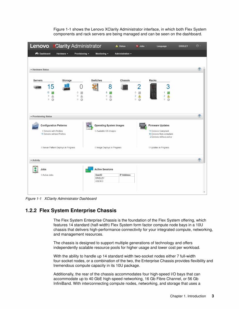
Figure 1-1 shows the Lenovo XClarity Administrator interface, in which both Flex System components and rack servers are being managed and can be seen on the dashboard.
Figure 1-1 XClarity Administrator Dashboard
1.2.2 Flex System Enterprise Chassis
The Flex System Enterprise Chassis is the foundation of the Flex System offering, which features 14 standard (half-width) Flex System form factor compute node bays in a 10U chassis that delivers high-performance connectivity for your integrated compute, networking, and management resources.
The chassis is designed to support multiple generations of technology and offers independently scalable resource pools for higher usage and lower cost per workload.
With the ability to handle up 14 standard width two-socket nodes either 7 full-width four-socket nodes, or a combination of the two, the Enterprise Chassis provides flexibility and tremendous compute capacity in its 10U package.
Additionally, the rear of the chassis accommodates four high-speed I/O bays that can accommodate up to 40 GbE high-speed networking, 16 Gb Fibre Channel, or 56 Gb InfiniBand. With interconnecting compute nodes, networking, and storage that uses a
Chapter 1. Introduction 3
high-performance and scalable mid-plane, the Enterprise Chassis can support the latest high-speed networking technologies.
The ground-up design of the Enterprise Chassis reaches new levels of energy efficiency through innovations in power, cooling, and air flow. By using simpler controls and futuristic designs, the Enterprise Chassis can break free of “one size fits all” energy schemes.
The ability to support the workload demands of tomorrow’s workloads is built in with a new I/O architecture, which provides choice and flexibility in fabric and speed. With the ability to use Ethernet, InfiniBand, Fibre Channel (FC), Fibre Channel over Ethernet (FCoE), and iSCSI, the Enterprise Chassis is uniquely positioned to meet the growing and future I/O needs of large and small businesses.
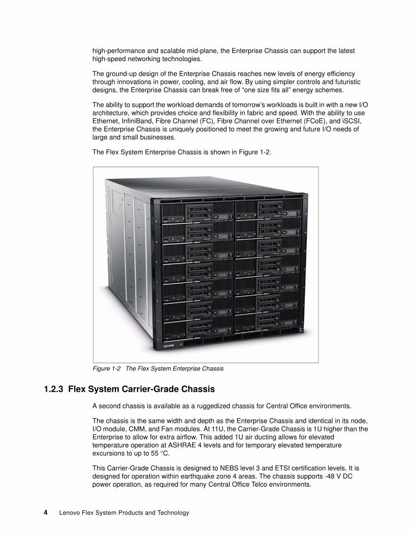
The Flex System Enterprise Chassis is shown in Figure 1-2.
Figure 1-2 The Flex System Enterprise Chassis
1.2.3 Flex System Carrier-Grade Chassis
A second chassis is available as a ruggedized chassis for Central Office environments.
The chassis is the same width and depth as the Enterprise Chassis and identical in its node, I/O module, CMM, and Fan modules. At 11U, the Carrier-Grade Chassis is 1U higher than the Enterprise to allow for extra airflow. This added 1U air ducting allows for elevated temperature operation at ASHRAE 4 levels and for temporary elevated temperature excursions to up to 55 °C.
This Carrier-Grade Chassis is designed to NEBS level 3 and ETSI certification levels. It is designed for operation within earthquake zone 4 areas. The chassis supports -48 V DC power operation, as required for many Central Office Telco environments.
4 Lenovo Flex System Products and Technology
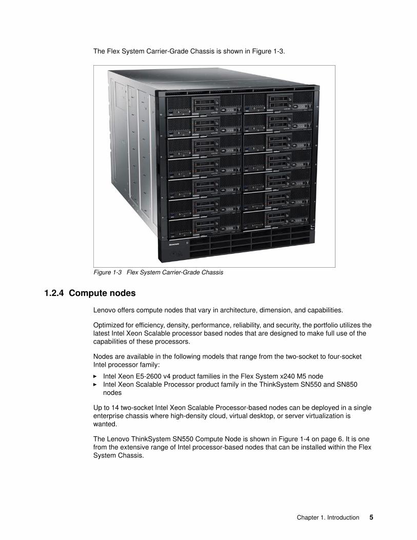
The Flex System Carrier-Grade Chassis is shown in Figure 1-3.
Figure 1-3 Flex System Carrier-Grade Chassis
1.2.4 Compute nodes
Lenovo offers compute nodes that vary in architecture, dimension, and capabilities.
Optimized for efficiency, density, performance, reliability, and security, the portfolio utilizes the latest Intel Xeon Scalable processor based nodes that are designed to make full use of the capabilities of these processors.
Nodes are available in the following models that range from the two-socket to four-socket Intel processor family:
� Intel Xeon E5-2600 v4 product families in the Flex System x240 M5 node� Intel Xeon Scalable Processor product family in the ThinkSystem SN550 and SN850
nodes
Up to 14 two-socket Intel Xeon Scalable Processor-based nodes can be deployed in a single enterprise chassis where high-density cloud, virtual desktop, or server virtualization is wanted.
The Lenovo ThinkSystem SN550 Compute Node is shown in Figure 1-4 on page 6. It is one from the extensive range of Intel processor-based nodes that can be installed within the Flex System Chassis.
Chapter 1. Introduction 5
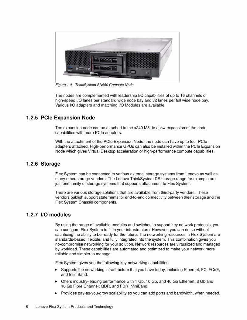
Figure 1-4 ThinkSystem SN550 Compute Node
The nodes are complemented with leadership I/O capabilities of up to 16 channels of high-speed I/O lanes per standard wide node bay and 32 lanes per full wide node bay. Various I/O adapters and matching I/O Modules are available.
1.2.5 PCIe Expansion Node
The expansion node can be attached to the x240 M5, to allow expansion of the node capabilities with more PCIe adapters.
With the attachment of the PCIe Expansion Node, the node can have up to four PCIe adapters attached. High-performance GPUs can also be installed within the PCIe Expansion Node which gives Virtual Desktop acceleration or high-performance compute capabilities.
1.2.6 Storage
Flex System can be connected to various external storage systems from Lenovo as well as many other storage vendors. The Lenovo ThinkSystem DS storage range for example are just one family of storage systems that supports attachment to Flex System.
There are various storage solutions that are available from third-party vendors. These vendors publish support statements for end-to-end connectivity between their storage and the Flex System Chassis components.
1.2.7 I/O modules
By using the range of available modules and switches to support key network protocols, you can configure Flex System to fit in your infrastructure. However, you can do so without sacrificing the ability to be ready for the future. The networking resources in Flex System are standards-based, flexible, and fully integrated into the system. This combination gives you no-compromise networking for your solution. Network resources are virtualized and managed by workload. These capabilities are automated and optimized to make your network more reliable and simpler to manage.
Flex System gives you the following key networking capabilities:
� Supports the networking infrastructure that you have today, including Ethernet, FC, FCoE, and InfiniBand.
� Offers industry-leading performance with 1 Gb, 10 Gb, and 40 Gb Ethernet; 8 Gb and 16 Gb Fibre Channel; QDR, and FDR InfiniBand.
� Provides pay-as-you-grow scalability so you can add ports and bandwidth, when needed.
6 Lenovo Flex System Products and Technology
Networking in data centers is undergoing a transition from a discrete traditional model to a more flexible, optimized model. The network architecture in Flex System was designed to address the key challenges that customers are facing today in their data centers. The key focus areas of the network architecture on this platform are unified network management, optimized and automated network virtualization, and simplified network infrastructure.
Providing innovation, leadership, and choice in the I/O module portfolio uniquely positions Flex System to provide meaningful solutions to address customer needs.
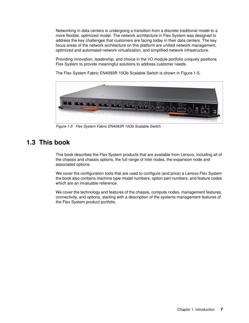
The Flex System Fabric EN4093R 10Gb Scalable Switch is shown in Figure 1-5.
Figure 1-5 Flex System Fabric EN4093R 10Gb Scalable Switch
1.3 This book
This book describes the Flex System products that are available from Lenovo, including all of the chassis and chassis options, the full range of Intel nodes, the expansion node and associated options.
We cover the configuration tools that are used to configure (and price) a Lenovo Flex System the book also contains machine type model numbers, option part numbers, and feature codes which are an invaluable reference.
We cover the technology and features of the chassis, compute nodes, management features, connectivity, and options, starting with a description of the systems management features of the Flex System product portfolio.
Chapter 1. Introduction 7

8 Lenovo Flex System Products and Technology
Chapter 2. Systems management
Lenovo XClarity Administrator is designed to help you get the most out of your Flex System installation. By using this highly capable management tool, you also can automate repetitive tasks. The management interface can significantly reduce the number of manual navigational steps for typical management tasks. Benefit from simplified system setup procedures, by using configuration patterns and built-in expertise to consolidate monitoring for physical and virtual resources.
This chapter includes the following topics:
� 2.1, “Management network” on page 10� 2.2, “Chassis Management Module” on page 13� 2.3, “Security” on page 16� 2.4, “Compute node management” on page 17� 2.5, “Lenovo XClarity Administrator” on page 23
2
Chassis types: The management architecture of the Flex System Enterprise Chassis is identical to the Flex System Carrier-Grade Chassis. Where the term Enterprise Chassis is used, it applies equally to both chassis.
© Copyright Lenovo 2018. All rights reserved. 9
2.1 Management network
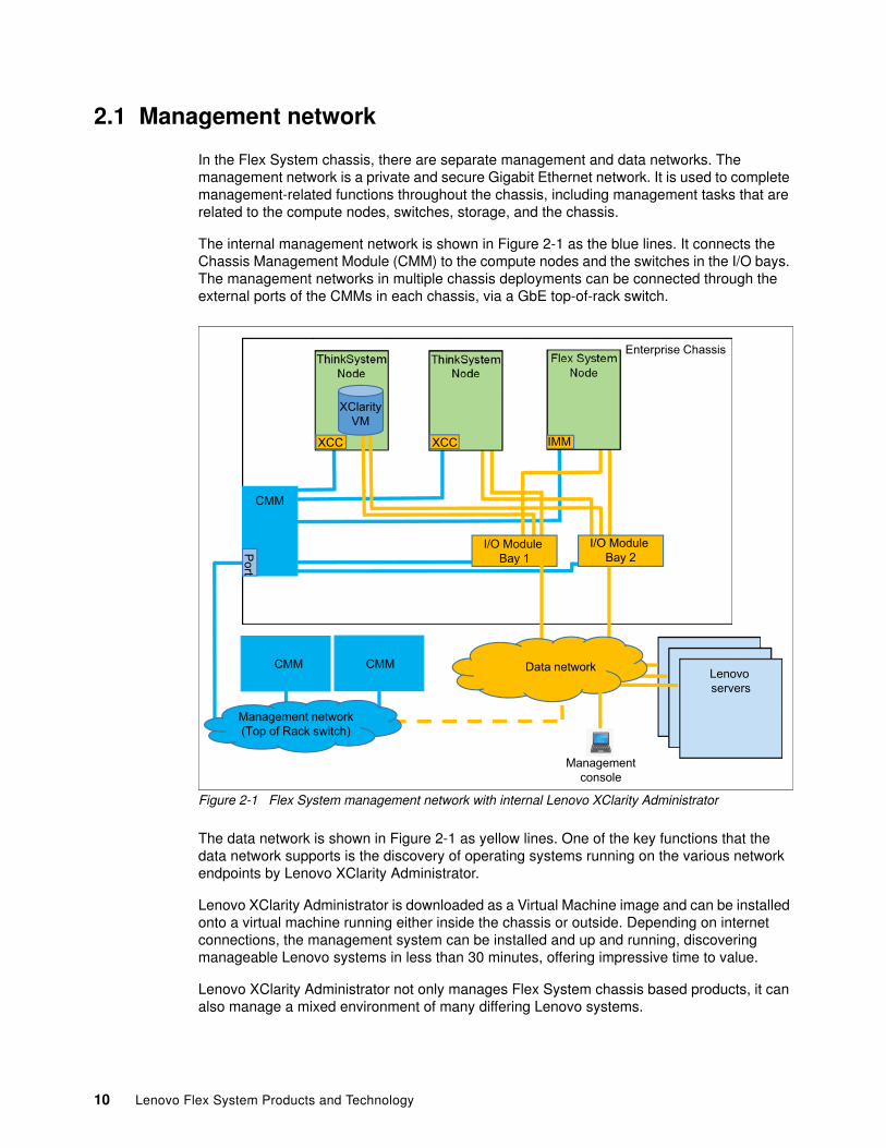
In the Flex System chassis, there are separate management and data networks. The management network is a private and secure Gigabit Ethernet network. It is used to complete management-related functions throughout the chassis, including management tasks that are related to the compute nodes, switches, storage, and the chassis.
The internal management network is shown in Figure 2-1 as the blue lines. It connects the Chassis Management Module (CMM) to the compute nodes and the switches in the I/O bays. The management networks in multiple chassis deployments can be connected through the external ports of the CMMs in each chassis, via a GbE top-of-rack switch.
Figure 2-1 Flex System management network with internal Lenovo XClarity Administrator
The data network is shown in Figure 2-1 as yellow lines. One of the key functions that the data network supports is the discovery of operating systems running on the various network endpoints by Lenovo XClarity Administrator.
Lenovo XClarity Administrator is downloaded as a Virtual Machine image and can be installed onto a virtual machine running either inside the chassis or outside. Depending on internet connections, the management system can be installed and up and running, discovering manageable Lenovo systems in less than 30 minutes, offering impressive time to value.
Lenovo XClarity Administrator not only manages Flex System chassis based products, it can also manage a mixed environment of many differing Lenovo systems.
Flex System Node
ThinkSystemNode
ThinkSystemNode
Port
IMMXCC
CMM
Enterprise Chassis
Management network(Top of Rack switch)
CMM CMM
I/O Module Bay 1
I/O Module Bay 2
XCC
XClarityVM
Lenovo servers
Data network
Managementconsole
10 Lenovo Flex System Products and Technology
Systems that can be managed by Lenovo XClarity Administrator include:
� Flex System nodes� ThinkSystem nodes� System x servers� ThinkServer servers� NeXtScale servers� ThinkAgile™ appliances� Lenovo DX storage solutions � Lenovo DS Series storage systems� Lenovo ThinkSystem & RackSwitch™ switches
Lenovo XClarity Administrator can discover chassis in your environment by probing for manageable systems that are on the same IP subnet as Lenovo XClarity Administrator by using a specified IP address or range of IP addresses or by importing information from a spreadsheet.
Figure 2-1 on page 10 shows Lenovo XClarity Administrator deployed within a Flex System environment. Here, the VM that contains Lenovo XClarity Administrator is installed within the Chassis on a node that is running a supported hypervisor. In this example, there is a single network (management and data). All communications between Lenovo XClarity Administrator and the network occurs over one (eth0) network interface on the host.
Chapter 2. Systems management 11
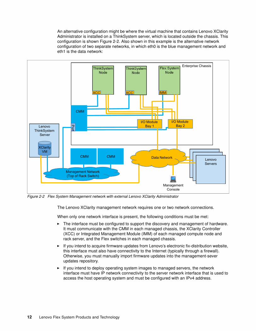
An alternative configuration might be where the virtual machine that contains Lenovo XClarity Administrator is installed on a ThinkSystem server, which is located outside the chassis. This configuration is shown Figure 2-2. Also shown in this example is the alternative network configuration of two separate networks, in which eth0 is the blue management network and eth1 is the data network:
Figure 2-2 Flex System Management network with external Lenovo XClarity Administrator
The Lenovo XClarity management network requires one or two network connections.
When only one network interface is present, the following conditions must be met:
� The interface must be configured to support the discovery and management of hardware. It must communicate with the CMM in each managed chassis, the XClarity Controller (XCC) or Integrated Management Module (IMM) of each managed compute node and rack server, and the Flex switches in each managed chassis.
� If you intend to acquire firmware updates from Lenovo’s electronic fix-distribution website, this interface must also have connectivity to the Internet (typically through a firewall). Otherwise, you must manually import firmware updates into the management-sever updates repository.
� If you intend to deploy operating system images to managed servers, the network interface must have IP network connectivity to the server network interface that is used to access the host operating system and must be configured with an IPv4 address.
Flex System Node
ThinkSystemNode
Port
IMMXCC
CMM
Enterprise Chassis
Management Network(Top of Rack Switch)
CMM CMM
I/O Module Bay 1
I/O Module Bay 2Lenovo
ThinkSystem Server
XClarityVM
XCC
ThinkSystemNode
LenovoServers
Data Network
ManagementConsole
12 Lenovo Flex System Products and Technology
When two network interfaces are (Eth0 and Eth1) present (as shown in Figure 2-2 on page 12), the following conditions must be met:
� The Eth0 interface often is connected to the management network and used to discover and manage hardware. It must communicate with the CMM of each managed chassis, the IMM2 of each managed server, and the Flex switches that are installed in each managed chassis.
� If you intend to acquire firmware updates from the Fix Central website, the Eth0 interface must also have connectivity to the Internet (typically through a firewall). Otherwise, you must import firmware updates into the management server updates repository.
� The Eth1 interface often is connected to the data network (an internal data network, a public data network, or both) and used to manage host operating systems.
� The network interface that you chose to use to deploy operating system images to the managed servers must have IP-network connectivity to the server network interface that is used to access the host operating system. It also must be configured with an IPv4 address.
� If you implemented a separate network for deploying operating systems, you can configure Eth1 to connect to that network instead of the data network. However, if the operating system deployment network does not have access to the data network, you must define another I/O interface on that server when you install the operating system on a server so that the server host has access to the data network.
For more information about the Lenovo XClarity Administrator features and functions, see 2.5, “Lenovo XClarity Administrator” on page 23.
2.2 Chassis Management Module
The CMM provides single-chassis management and is used to communicate with the management controller in each compute node. It provides system monitoring, event recording, and alerts. It also manages the chassis, its devices, and the compute nodes. The chassis supports up to two CMMs. If one CMM fails, the second CMM can detect its inactivity, self-activate, and take control of the system without any disruption. The CMM is central to the management of the chassis and is required in the Enterprise Chassis
CMM2 is the Chassis Management Module that is currently available from Lenovo. The original CMM is now withdrawn from marketing.
Table 2-1 CMM2
The next section describes the usage models of the CMM and its features.
For more information about the CMM see 3.6, “Chassis Management Module” on page 63.
2.2.1 Overview
The CMM is a hot-swap module that provides basic system management functions for all devices that are installed in the Enterprise Chassis. A chassis includes at least one CMM and supports CMM redundancy.
Part Number Description Chassis Model
00FJ669 Flex System Chassis Management Module 2 All available
Chapter 2. Systems management 13
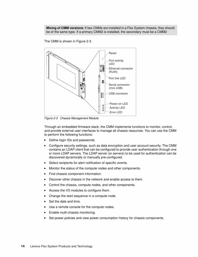
The CMM is shown in Figure 2-3.
Figure 2-3 Chassis Management Module
Through an embedded firmware stack, the CMM implements functions to monitor, control, and provide external user interfaces to manage all chassis resources. You can use the CMM to perform the following functions:
� Define login IDs and passwords.
� Configure security settings, such as data encryption and user account security. The CMM contains an LDAP client that can be configured to provide user authentication through one or more LDAP servers. The LDAP server (or servers) to be used for authentication can be discovered dynamically or manually pre-configured.
� Select recipients for alert notification of specific events.
� Monitor the status of the compute nodes and other components.
� Find chassis component information.
� Discover other chassis in the network and enable access to them.
� Control the chassis, compute nodes, and other components.
� Access the I/O modules to configure them.
� Change the start sequence in a compute node.
� Set the date and time.
� Use a remote console for the compute nodes.
� Enable multi-chassis monitoring.
� Set power policies and view power consumption history for chassis components.
Mixing of CMM versions: If two CMMs are installed in a Flex System chassis, they should be of the same type. If a primary CMM2 is installed, the secondary must be a CMM2
14 Lenovo Flex System Products and Technology
2.2.2 Interfaces
The CMM supports a web-based graphical user interface (GUI) that provides a way to perform chassis management functions within a supported web browser. You can also perform management functions through the CMM command-line interface (CLI). The web-based and CLI interfaces are accessible through the single RJ45 Ethernet connector on the CMM, or from any system that is connected to the same network.
The CMM has the following default IPv4 settings:
� IP address: 192.168.70.100� Subnet: 255.255.255.0� User ID: USERID (all capital letters)� Password: PASSW0RD (all capital letters, with a zero instead of the letter O)
The CMM does not have a fixed static IPv6 IP address by default. Initial access to the CMM in an IPv6 environment can be done by using the IPv4 IP address or the IPv6 link-local address. The IPv6 link-local address is automatically generated based on the MAC address of the CMM. By default, the CMM is configured to respond to DHCP first before it uses its static IPv4 address. If you do not want this operation to occur, connect locally to the CMM and change the default IP settings. For example, you can connect locally by using a notebook.
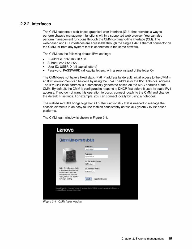
The web-based GUI brings together all of the functionality that is needed to manage the chassis elements in an easy-to-use fashion consistently across all System x IMM2 based platforms.
The CMM login window is shown in Figure 2-4.
Figure 2-4 CMM login window
Chapter 2. Systems management 15
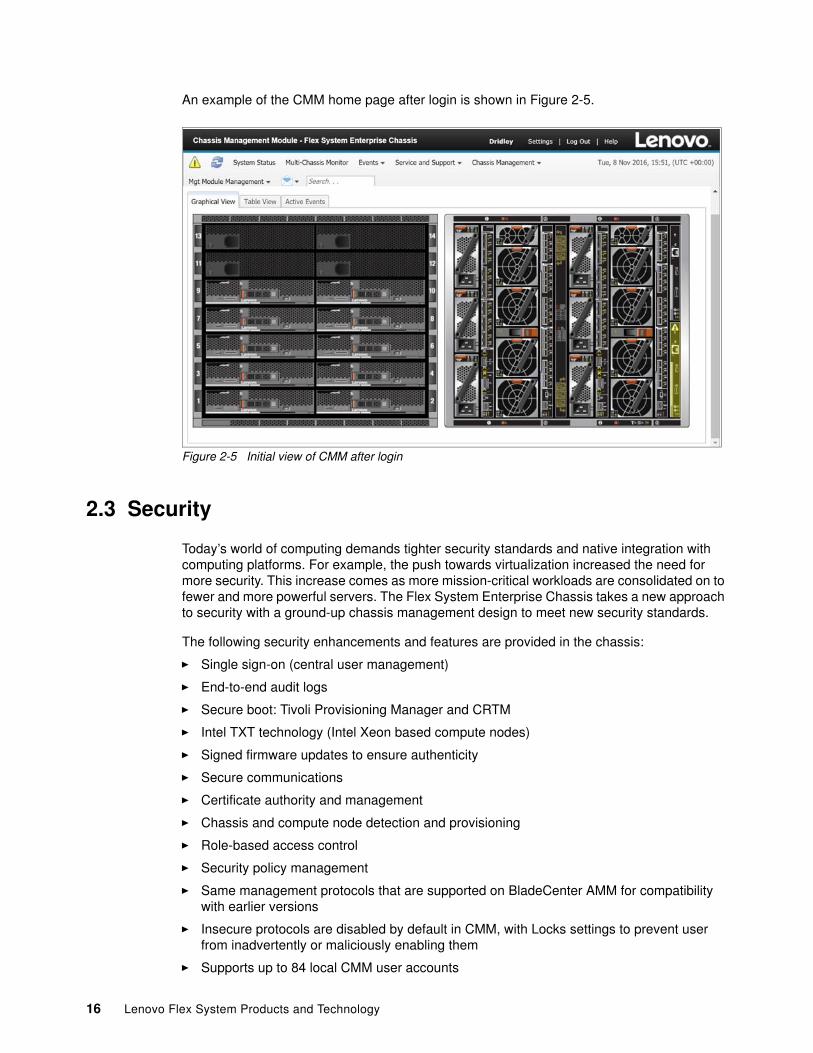
An example of the CMM home page after login is shown in Figure 2-5.
Figure 2-5 Initial view of CMM after login
2.3 Security
Today’s world of computing demands tighter security standards and native integration with computing platforms. For example, the push towards virtualization increased the need for more security. This increase comes as more mission-critical workloads are consolidated on to fewer and more powerful servers. The Flex System Enterprise Chassis takes a new approach to security with a ground-up chassis management design to meet new security standards.
The following security enhancements and features are provided in the chassis:
� Single sign-on (central user management)
� End-to-end audit logs
� Secure boot: Tivoli Provisioning Manager and CRTM
� Intel TXT technology (Intel Xeon based compute nodes)
� Signed firmware updates to ensure authenticity
� Secure communications
� Certificate authority and management
� Chassis and compute node detection and provisioning
� Role-based access control
� Security policy management
� Same management protocols that are supported on BladeCenter AMM for compatibility with earlier versions
� Insecure protocols are disabled by default in CMM, with Locks settings to prevent user from inadvertently or maliciously enabling them
� Supports up to 84 local CMM user accounts
16 Lenovo Flex System Products and Technology
� Supports up to 32 simultaneous sessions
� CMM supports LDAP authentication
The Enterprise Chassis ships Secure and supports the following security policy settings:
� Secure: Default setting to ensure a secure chassis infrastructure and includes the following features:
– Strong password policies with automatic validation and verification checks
– Updated passwords that replace the manufacturing default passwords after the initial setup
– Only secure communication protocols, such as Secure Shell (SSH) and Secure Sockets Layer (SSL)
– Certificates to establish secure, trusted connections for applications that run on the management processors
� Legacy: Flexibility in chassis security, which includes the following features:
– Weak password policies with minimal controls
– Manufacturing default passwords that do not have to be changed
– Decrypted communication protocols, such as Telnet, SNMPv1, TCP Command Mode, FTP Server, and TFTP Server
� Trusted Platform Module (TPM):
– CMM2: Trusted Platform Module v2.0
The centralized security policy makes Enterprise Chassis easy to configure. All components run with the same security policy that is provided by the CMM. This consistency ensures that all I/O modules run with a hardened attack surface.
The CMM and Lenovo XClarity Administrator each have their own independent security policies that control, audit, and enforce the security settings. The security settings include the network settings and protocols, password and firmware update controls, and trusted computing properties.
2.4 Compute node management
Each node in the Enterprise Chassis has a management controller that communicates upstream through the CMM-enabled 1 GbE private management network that enables management capability.
The management controllers for the various Enterprise Chassis components have the following default IPv4 addresses:
� CMM: 192.168.70.100 � Compute nodes: 192.168.70.101-114 (corresponding to the slots 1 - 14 in the chassis)� I/O Modules: 192.168.70.120-123 (sequentially corresponding to chassis bay numbering)
In addition to the IPv4 address, all I/O modules support link-local IPv6 addresses and configurable external IPv6 addresses.
Chapter 2. Systems management 17

2.4.1 XClarity Controller
With the announcement of the ThinkSystem brand, a new improved management controller was launched, known as XClarity Controller or XCC.
XCC has many improvements over the previous generation IMM2. Boot times have been improved to the extent that systems are twice as fast booting, some firmware updates can be applied six times faster than the previous x240 M5 generation.
The User experience is much improved when managing a ThinkSystem node via the integrated XCC management controller web interface. The GUI has intuitive dashboards featuring an “at a glance” main screen giving access to most common system actions.
Other improvements include:
� Support for HTML5 - no longer a need for Java or Active X
� Support access via the XClarity Mobile application, via the front USB port located on the node front panel
� Support for XClarity Provisioning Manager
� Remote configuration using XClarity Essentials or XClarity Controller CLI.
� Enhanced remote-presence capabilities.
� REST API (Redfish schema) support for additional web-related services and software applications. It currently supports Redfish Scalable Platforms Management API Specification 1.0.2 and schema 2016.2
There are three levels of features available with XCC:
� Standard� Advanced� Enterprise
ThinkSystem nodes ship with the enterprise level enabled as standard, which provides full function, including mounting of local ISO/IMG files, remote virtual media mounting of ISO/IMG files and most importantly, allow remote deployment when using XClarity Administrator.
Figure 2-6 on page 19 shows the improved interface that is presented when logged into the XCC, on a ThinkSystem SN550 node. Health summary, system information, settings and power utilization can be quickly seen on this one screen with much further information and quick actions being available with simple clicks of the mouse.
18 Lenovo Flex System Products and Technology

Figure 2-6 XClarity Controller web interface
Local management using XClarity mobile applicationThe ThinkSystem SN550 and SN850 nodes have a new feature for direct USB management that is common on all of the XCC managed ThinkSystem Servers.
This allows the front panel USB 3.0 port to be used for management of the node, when the node is installed into a chassis. The node does not need to be powered up for this management method to function. When a suitable connected USB device (iOS or Android) running XClarity Administrator mobile application is connected, an Ethernet over USB connection can be established between the mobile app running on the device and the XClarity Controller.
The mobile application can be downloaded from the relevant application stores:
� Google Play� Apple iTunes� Lenovo Store (China)� Baidu Store (China)
The USB port on the Node can be enabled in a number of different modes:
� Host only mode: USB port is only connected to the Server. This means the OS that is running on the server will “see” the USB port.
� BMC only mode: USB port is connected only to XCC. This means the OS will not “see” the USB port, as the port is dedicated to the XCC.
Chapter 2. Systems management 19
� Shared mode owned by BMC: USB port is shared by both the server and the XCC, but the port is switched to the XCC
� Shared mode owned by the host: USB port is shared by both the server and the XCC but the port is switched to the XCC
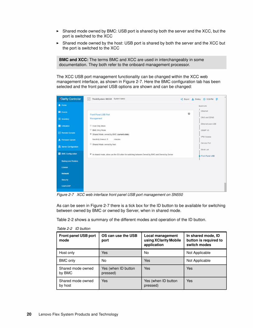
The XCC USB port management functionality can be changed within the XCC web management interface, as shown in Figure 2-7. Here the BMC configuration tab has been selected and the front panel USB options are shown and can be changed:
Figure 2-7 XCC web interface front panel USB port management on SN550
As can be seen in Figure 2-7 there is a tick box for the ID button to be available for switching between owned by BMC or owned by Server, when in shared mode.
Table 2-2 shows a summary of the different modes and operation of the ID button.
Table 2-2 ID button
BMC and XCC: The terms BMC and XCC are used in interchangeably in some documentation. They both refer to the onboard management processor.
Front panel USB port mode
OS can use the USB port
Local management using XClarity Mobile application
In shared mode, ID button is required to switch modes
Host only Yes No Not Applicable
BMC only No Yes Not Applicable
Shared mode owned by BMC
Yes (when ID button pressed)
Yes Yes
Shared mode owned by host
Yes Yes (when ID button pressed)
Yes
20 Lenovo Flex System Products and Technology
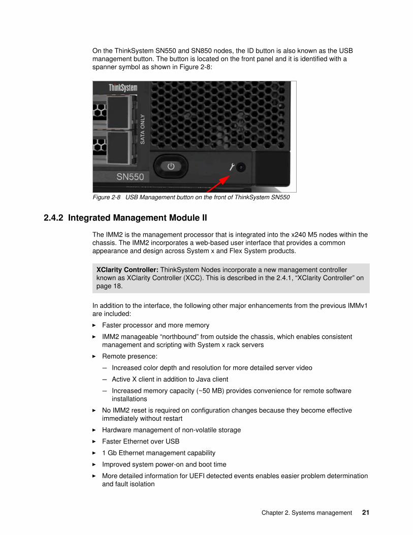
On the ThinkSystem SN550 and SN850 nodes, the ID button is also known as the USB management button. The button is located on the front panel and it is identified with a spanner symbol as shown in Figure 2-8:
Figure 2-8 USB Management button on the front of ThinkSystem SN550
2.4.2 Integrated Management Module II
The IMM2 is the management processor that is integrated into the x240 M5 nodes within the chassis. The IMM2 incorporates a web-based user interface that provides a common appearance and design across System x and Flex System products.
In addition to the interface, the following other major enhancements from the previous IMMv1 are included:
� Faster processor and more memory
� IMM2 manageable “northbound” from outside the chassis, which enables consistent management and scripting with System x rack servers
� Remote presence:
– Increased color depth and resolution for more detailed server video
– Active X client in addition to Java client
– Increased memory capacity (~50 MB) provides convenience for remote software installations
� No IMM2 reset is required on configuration changes because they become effective immediately without restart
� Hardware management of non-volatile storage
� Faster Ethernet over USB
� 1 Gb Ethernet management capability
� Improved system power-on and boot time
� More detailed information for UEFI detected events enables easier problem determination and fault isolation
XClarity Controller: ThinkSystem Nodes incorporate a new management controller known as XClarity Controller (XCC). This is described in the 2.4.1, “XClarity Controller” on page 18.
Chapter 2. Systems management 21
� User interface meets accessibility standards (CI-162 compliant)
� Separate audit and event logs
� “Trusted” IMM with significant security enhancements (CRTM/TPM, signed updates, authentication policies, and so on)
� Simplified update and flashing mechanism
� Syslog alerting mechanism provides an alternative to e-mail and SNMP traps
� Support for Features on Demand (FoD) enablement of server functions, option card features, and System x solutions and applications
� First Failure Data Capture: One button web press starts data collection and download
For more information about IMM2 as implemented in Flex System compute nodes, see Chapter 5, “Compute nodes” on page 209.
For more information, see Integrated Management Module II User’s Guide available from:
https://download.lenovo.com/servers_pdf/nn1jz_book.pdf
2.4.3 I/O modules
The I/O modules include the following base functions:
� Initialization� Configuration� Diagnostic tests (power-on and concurrent)� Status Reporting
The following set of protocols and software features also are supported on the I/O modules:
� A configuration method over the Ethernet management port.
� A scriptable SSH CLI, a web server with SSL support, Simple Network Management Protocol v3 (SNMPv3) Agent with alerts, and a sFTP client.
� Server ports that are used for Telnet, HTTP, SNMPv1 agents, TFTP, FTP, and other insecure protocols are DISABLED by default.
� LDAP authentication protocol support for user authentication.
� For Ethernet I/O modules, 802.1x enabled with policy enforcement point (PEP) capability to allow support of TNC (Trusted Network Connect).
� The ability to capture and apply a switch configuration file and the ability to capture a first failure data capture (FFDC) data file.
� Ability to transfer files by using URL update methods (HTTP, HTTPS, FTP, TFTP, and sFTP).
� Various methods for firmware updates, including FTP, sFTP, and TFTP. In addition, firmware updates by using a URL that includes protocol support for HTTP, HTTPs, FTP, sFTP, and TFTP.
� SLP discovery and SNMPv3.
� Ability to detect firmware and hardware hangs and to pull a “crash-failure memory dump” file to an FTP (sFTP) server.
� Selectable primary and backup firmware banks as the current operational firmware.
� Ability to send events, SNMP traps, and event logs to the CMM, including security audit logs.
22 Lenovo Flex System Products and Technology
� IPv4 and IPv6 on by default.
� The CMM management port supports IPv4 and IPv6 (IPV6 support includes the use of link local addresses.
� Port mirroring capabilities:
– Port mirroring of CMM ports to internal and external ports.
– For security reasons, the ability to mirror the CMM traffic is hidden and is available to development and service personnel only.
� Management virtual local area network (VLAN) for Ethernet switches: A configurable management 802.1q tagged VLAN in the standard VLAN range of 1 - 4094. It includes the CMM’s internal management ports and the I/O modules internal ports that are connected to the nodes.
2.5 Lenovo XClarity Administrator
Lenovo XClarity Administrator is centralized resource management solution that is aimed at reducing complexity, speeding response, and enhancing availability of Lenovo server systems and solutions.
Lenovo XClarity Administrator provides agent-free hardware management for ThinkSystem and System x rack servers, as well as ThinkSystem and Flex System compute nodes, including components such as the CMM and Flex System I/O modules. It is an ideal management platform for the Lenovo Flex System.
Lenovo XClarity Administrator is a virtual appliance that is quickly imported into a virtualized environment, which gives easy deployment and portability. This virtualized appliance design is a key advantage because there is no need to dedicate a node bay. The VM can be hosted on a physical server located either inside or outside of the Chassis.
Managed endpoints do not need special software agents or drivers to be installed or maintained to be managed by Lenovo XClarity Administrator. Being agentless also means that Lenovo XClarity Administrator removes operating system dependency and is one less component to certify in the workload stack, which results in management simplicity.
Because Lenovo XClarity Administrator is a virtual appliance, it can use VMware High Availability and Hyper-V clustering for failover capability.
The administration dashboard based on HTML 5 allows fast location of resources so tasks can be run quickly. Because Lenovo XClarity Administrator does not have any agent software that is installed on the managed endpoints, there are no CPU cycles that are spent on agent execution and no memory used. Therefore, up to 1 GB of RAM and 1 - 2% CPU usage is saved, compared to a typical managed system in which an agent is required.
With a simplified administration dashboard, the following functions are easily achieved:
� Discovery� Inventory� Monitoring� Firmware updates� Firmware compliance� Configuration management � Deployment of operating systems and hypervisors to bare metal servers
Chapter 2. Systems management 23
Fast time to value is realized through automatic discovery of existing or new Lenovo ThinkSystem, rack servers, System x rack servers and Flex System infrastructure. Inventory of the discovered endpoints is gathered, so an at-a-glance view of the managed hardware inventory and its status is possible.
A centralized view of events and alerts that are generated from managed endpoints, such as Flex System chassis, ThinkSystem servers, and Flex System switches, is available. When an issue is detected by a managed endpoint, an event is passed to Lenovo XClarity Administrator. Alerts and events are visible via the XClarity Administrator Dashboard, the Status bar, and via the Alerts and Events detail for the specific system.
Firmware management is simplified by assigning compliance policies to managed endpoints. The compliance policy can be created and XClarity Administrator monitors changes to the hardware inventory and flags any previous non-compliant systems.
Configuration management uses pattern-based configurations to quickly provision and reprovision a single server or multiple servers and compute nodes, all with a single set of configuration settings. Address pools can be configured to assist with deployments. Category patterns are used to create configuration patterns that can be deployed to server profiles.
Provisioning enables firmware management, configuration, and bare metal deployment. VMware ESXi, Windows Server, and Red Hat Linux images can be imported and held in a repository for images. Up to 28 OS images can be deployed concurrently.
If you must be compliant to NIST SP 800-131A or FIPS 140-2, Lenovo XClarity Administrator can help you achieve a fully compliant environment. Lenovo XClarity Administrator supports self-signed SSL certificates (which are issued by an internal certificate authority) or external SSL certificates (private or commercial CA). Lenovo XClarity includes an audit log that provides a historical record of user actions, such as logging on, new users, or changing user passwords.
Lenovo XClarity can be integrated into external, higher-level management, automation, and orchestration platforms through open REST application programming interfaces (APIs). This ability means Lenovo XClarity can easily integrate with your management infrastructure.
2.5.1 Lenovo XClarity Administrator management tasks
By using Lenovo XClarity, you can perform the following main tasks:
� User management
Lenovo XClarity Administrator provides a centralized authentication server to create and manage all user accounts and to manage and authenticate user credentials. The authentication server is created automatically when the management server first starts.
The User accounts that are used to log on and manage the Lenovo XClarity Administrator are also used for all chassis and servers that are managed by the Lenovo XClarity Administrator. When you create a user account, you control the level of access (such as whether the account has read/write authority or read-only authority) by using predefined role groups.
� Hardware monitoring
Lenovo XClarity Administrator provides a centralized view of events and alerts that are generated from managed endpoints, such as chassis, servers, and Flex System switches. When an issue is detected by the CMM or device that is installed in the chassis, an event is passed to the Lenovo XClarity Administrator. That event is displayed in the alerts list
24 Lenovo Flex System Products and Technology
that is available within the user interface. A status bar also is available that provides overall status information about the main XClarity Administrator interface.
� Hardware management
There are various management tasks for each supported endpoint, including viewing status and properties, configuring system information and network settings, starting the CMM/IMM web interface, and remotely controlling the ThinkSystem, System x or Flex system node.
� Configuration management
Configuration patterns provide a way to ensure that you have a consistent configuration that is applied to managed servers. Server patterns are used to provision or pre-provision a managed server by configuring local storage, I/O adapters, boot setting, firmware, ports, IMM, and UEFI settings. Server patterns also integrate support for virtualizing I/O addresses, so you can virtualize Flex System fabric connections or repurpose servers without disruption to the fabric.
� Operating system deployment
Lenovo XClarity Administrator can be used to manage the operating system images repository and deploy operating system images to managed servers. To deploy an operating system image from Lenovo XClarity, at least one of the network interfaces (Eth0 or Eth1) must have IP network connectivity to the server network interface that is used to access the host operating system and must be configured with an IPv4 address.
� Firmware updates
Within Lenovo XClarity, you can manage the firmware updates repository and apply and activate firmware updates for all managed endpoints. Compliance policies can be instigated to flag managed endpoints that do not comply with the firmware rules that are defined. Refreshing the repository and downloading updates requires an Internet connection. If Lenovo XClarity has no Internet connection, you can manually import updates to the repository.
� Task automation that uses scripts
Lenovo XClarity Administrator can run provided cmdlets in a Microsoft PowerShell session to automate certain management functions. The cmdlets use Lenovo XClarity REST APIs and can automate the following functions:
– Logging in to Lenovo XClarity Administrator– Managing user accounts– Managing a chassis– Deploying an operating system image to one or more compute nodes or rack servers– Configuring compute nodes and rack servers by using configuration patterns
2.5.2 Lenovo XClarity Administrator licensing
Lenovo XClarity Administrator is available in two distinct editions:
� Lenovo XClarity Administrator � Lenovo XClarity Pro
The differences between each version of Lenovo XClarity is shown in Table 2-3.
Table 2-3 XClarity Administrator editions
XClarity edition XClarity Administrator
XClarity Pro
Cost Structure No Charge Chargeable
Chapter 2. Systems management 25
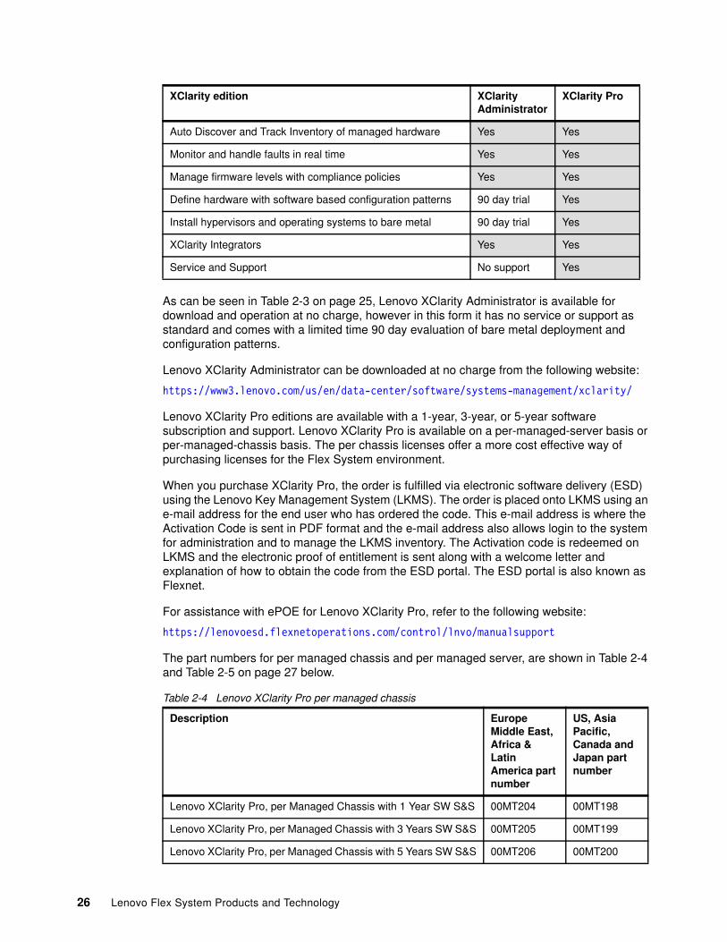
As can be seen in Table 2-3 on page 25, Lenovo XClarity Administrator is available for download and operation at no charge, however in this form it has no service or support as standard and comes with a limited time 90 day evaluation of bare metal deployment and configuration patterns.
Lenovo XClarity Administrator can be downloaded at no charge from the following website:
https://www3.lenovo.com/us/en/data-center/software/systems-management/xclarity/
Lenovo XClarity Pro editions are available with a 1-year, 3-year, or 5-year software subscription and support. Lenovo XClarity Pro is available on a per-managed-server basis or per-managed-chassis basis. The per chassis licenses offer a more cost effective way of purchasing licenses for the Flex System environment.
When you purchase XClarity Pro, the order is fulfilled via electronic software delivery (ESD) using the Lenovo Key Management System (LKMS). The order is placed onto LKMS using an e-mail address for the end user who has ordered the code. This e-mail address is where the Activation Code is sent in PDF format and the e-mail address also allows login to the system for administration and to manage the LKMS inventory. The Activation code is redeemed on LKMS and the electronic proof of entitlement is sent along with a welcome letter and explanation of how to obtain the code from the ESD portal. The ESD portal is also known as Flexnet.
For assistance with ePOE for Lenovo XClarity Pro, refer to the following website:
https://lenovoesd.flexnetoperations.com/control/lnvo/manualsupport
The part numbers for per managed chassis and per managed server, are shown in Table 2-4 and Table 2-5 on page 27 below.
Table 2-4 Lenovo XClarity Pro per managed chassis
Auto Discover and Track Inventory of managed hardware Yes Yes
Monitor and handle faults in real time Yes Yes
Manage firmware levels with compliance policies Yes Yes
Define hardware with software based configuration patterns 90 day trial Yes
Install hypervisors and operating systems to bare metal 90 day trial Yes
XClarity Integrators Yes Yes
Service and Support No support Yes
Description Europe Middle East, Africa & Latin America part number
US, Asia Pacific, Canada and Japan part number
Lenovo XClarity Pro, per Managed Chassis with 1 Year SW S&S 00MT204 00MT198
Lenovo XClarity Pro, per Managed Chassis with 3 Years SW S&S 00MT205 00MT199
Lenovo XClarity Pro, per Managed Chassis with 5 Years SW S&S 00MT206 00MT200
XClarity edition XClarity Administrator
XClarity Pro
26 Lenovo Flex System Products and Technology
Table 2-5 Lenovo XClarity Pro per managed server
2.5.3 Lenovo XClarity host requirements
The Lenovo XClarity management appliance runs in a virtual machine on the host system. The host system that is running the Lenovo XClarity virtual machine features the following minimum hardware requirements:
� Two virtual microprocessors� 8GB of memory� A minimum of 192 GB of storage for use by Lenovo XClarity virtual appliance
The following Hypervisors are currently supported for installing Lenovo XClarity:
� Nutanix Acropolis Hypervisor (AHV)� Microsoft Windows Server 2016 with Hyper-V installed� Microsoft Windows Server 2012 R2 with Hyper-V installed� Microsoft Windows Server 2012 with Hyper-V installed� Red Hat Enterprise Linux 7.x with Kernel-based Virtual Machine (KVM) v1.2.17 installed� VMware ESXi 6.5� VMware ESXi 6.0 U1 and U2� VMware ESXi 5.5 U1 and U2� VMware ESXi 5.1 U1, U2, and U3
For VMware, the virtual machine is available as an OVF template. For Hyper-V, the virtual machine is a virtual disk image and for KVM it is qcow2 format.
For the latest list of supported host systems which has consistently been enhanced since launch, please refer to the following website:
http://sysmgt.lenovofiles.com/help/topic/com.lenovo.lxca.doc/plan_lxcaprerequisites.html
Note: Managed Chassis licensing is often a more cost effective way to license Flex System deployments.
Description Europe Middle East, Africa & Latin America part number
US, Asia Pacific, Canada and Japan part number
Lenovo XClarity Pro, per Managed Server with 1 Year SW S&S 00MT207 00MT201
Lenovo XClarity Pro, per Managed Server with 3 Years SW S&S 00MT208 00MT201
Lenovo XClarity Pro, per Managed Server with 5 years SW S&S 00MT209 00MT203
NUMA and Hyper-V: For Hyper-V environments that run on Linux guests with a 2.6 kernel base and that use large amounts of memory for the virtual appliance, you must disable the use of non-uniform memory access (NUMA) on the Hyper-V Settings Panel from Hyper-V Manager. Changing this setting requires you to restart the Hyper-V service, which also restarts all running virtual machines. If this setting is not disabled, Lenovo XClarity Administrator virtual appliance might experience problems during initial startup.
Chapter 2. Systems management 27
2.5.4 Supported managed endpoints
The lists of supported Flex System compute nodes, ThinkSystem servers, and other devices that can be managed by Lenovo XClarity are constantly being updated and enhanced.
Where some systems may have older IBM Signed firmware, there are some limitations on functionality:
� Servers with IBM signed firmware are supported however, the following functions are not available:
– Processor and memory usage data
– RAID-link configuration (configuration management by using patterns)
� I/O modules with IBM signed firmware are supported however, the following functions are not available:
– Aggregated event and audit logs
– Network configuration (port configuration via configuration management by using patterns)
� Chassis Management Module: For full function, the Flex System Enterprise Chassis requires one or two Chassis Management Module 2 (CMM2) installed (part number 00FJ669). The CMM2 features Lenovo signed firmware. A chassis that contains a first-generation CMM with IBM signed firmware is supported; however, the following functions are not available:
– Aggregated event and audit logs from I/O Modules
– Network configuration (port configuration via configuration management that uses patterns)
� V7000 Storage Node: Lenovo XClarity provides Support with some functions that are limited for Flex System V7000 Storage Nodes, including displaying status and detailed information, powering on and off, virtually reseating the canisters, and starting the management module.
There are minimum levels of firmware that is required for each managed endpoint and these are detailed in the Lenovo XClarity Administrator online documentation.
Requirements for firmware, chassis and chassis management modules, compute and storage nodes, embedded switches, I/O adapters, storage adapters, hard disk drives and solid state drives are all covered in the following documents:
� Flex System and ThinkSystem devices in a Flex System chassis:
https://datacentersupport.lenovo.com/us/en/solutions/ht503453#FlexNode
� ThinkSystem, Converged HX, NeXtScale, and System x servers:
https://datacentersupport.lenovo.com/us/en/solutions/ht503455#HxServ
� ThinkSystem servers:
https://datacentersupport.lenovo.com/us/en/solutions/ht503472#TSServ
� RackSwitch switches:
https://datacentersupport.lenovo.com/us/en/solutions/ht503468#RackTor
CMM: It is not possible for a CMM that is signed by IBM and a CMM2 that is signed by Lenovo to be installed within a chassis at the same time. The firmware on a CMM cannot be upgraded to make a CMM2 because they contain different hardware.
28 Lenovo Flex System Products and Technology

� Lenovo storage, ThinkSystem storage:
https://datacentersupport.lenovo.com/us/en/solutions/ht503470#StorDev
Full information on Lenovo XClarity Administrator can be found at the following address:
http://sysmgt.lenovofiles.com/help/index.jsp?topic=%2Fcom.lenovo.lxca.doc
Chapter 2. Systems management 29

30 Lenovo Flex System Products and Technology
Chapter 3. Chassis and infrastructure configuration
There are two available Flex System chassis: the Enterprise Chassis and the Carrier-Grade Chassis.
The Lenovo Flex System Enterprise Chassis (machine type 8721) is a 10U next-generation server platform with integrated chassis management. It is a compact, high-density, high-performance, rack-mount, scalable platform system.
The Carrier-Grade Chassis (machine type 7385) is also available for use in harsher Telecommunications environments where NEBS Level 3 or ETSI certification is required. This chassis is based on the Flex System Enterprise Chassis, and incorporates extra cooling capability for elevated temperature operation. The Carrier-Grade chassis is 11U in height.
Both chassis support up to 14 standard compute nodes. The compute nodes share common resources, such as power, cooling, management, and I/O resources within a single chassis.
This chapter includes the following topics:
� 3.1, “Enterprise Chassis” on page 32� 3.2, “Carrier-Grade Chassis” on page 37� 3.3, “Fan modules” on page 46� 3.4, “Cooling” on page 51� 3.5, “Power supplies” on page 57� 3.6, “Chassis Management Module” on page 63� 3.7, “Other chassis components” on page 65� 3.8, “Infrastructure planning” on page 70� 3.9, “42U 1100mm Enterprise V2 Dynamic Rack” on page 82� 3.10, “Rear Door Heat eXchanger V2 Type 1756” on page 87
3
© Copyright Lenovo 2018. All rights reserved. 31
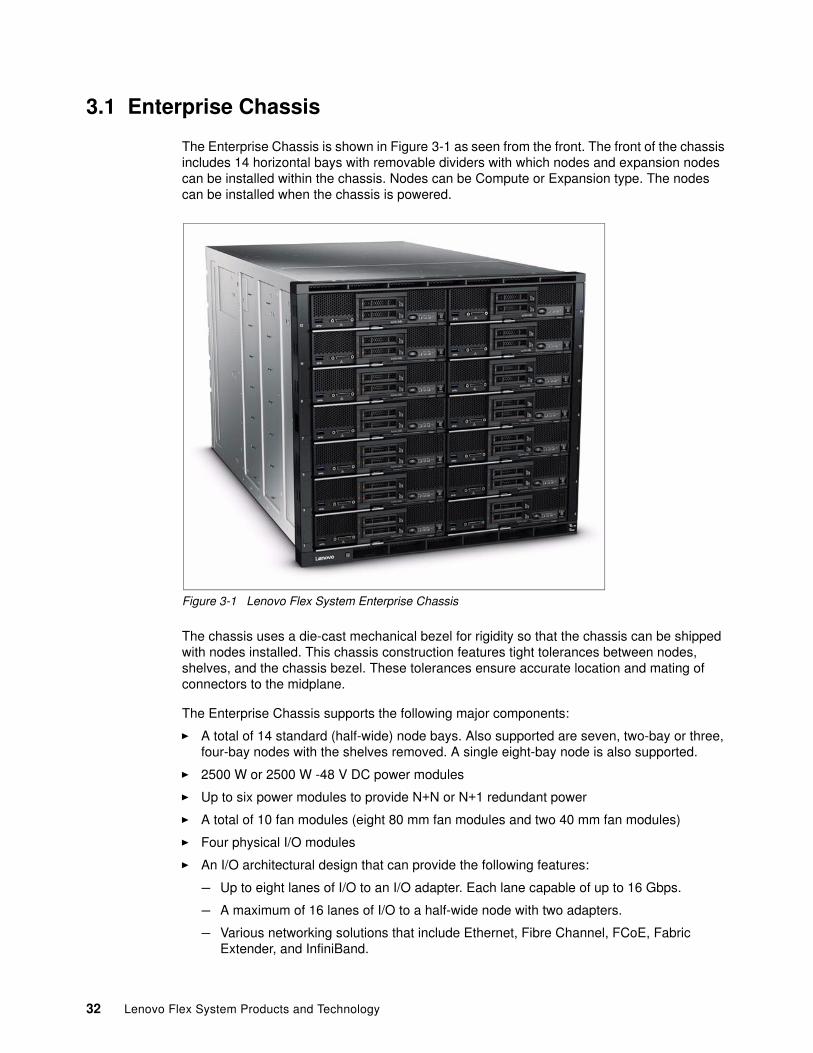
3.1 Enterprise Chassis
The Enterprise Chassis is shown in Figure 3-1 as seen from the front. The front of the chassis includes 14 horizontal bays with removable dividers with which nodes and expansion nodes can be installed within the chassis. Nodes can be Compute or Expansion type. The nodes can be installed when the chassis is powered.
Figure 3-1 Lenovo Flex System Enterprise Chassis
The chassis uses a die-cast mechanical bezel for rigidity so that the chassis can be shipped with nodes installed. This chassis construction features tight tolerances between nodes, shelves, and the chassis bezel. These tolerances ensure accurate location and mating of connectors to the midplane.
The Enterprise Chassis supports the following major components:
� A total of 14 standard (half-wide) node bays. Also supported are seven, two-bay or three, four-bay nodes with the shelves removed. A single eight-bay node is also supported.
� 2500 W or 2500 W -48 V DC power modules
� Up to six power modules to provide N+N or N+1 redundant power
� A total of 10 fan modules (eight 80 mm fan modules and two 40 mm fan modules)
� Four physical I/O modules
� An I/O architectural design that can provide the following features:
– Up to eight lanes of I/O to an I/O adapter. Each lane capable of up to 16 Gbps.
– A maximum of 16 lanes of I/O to a half-wide node with two adapters.
– Various networking solutions that include Ethernet, Fibre Channel, FCoE, Fabric Extender, and InfiniBand.
32 Lenovo Flex System Products and Technology
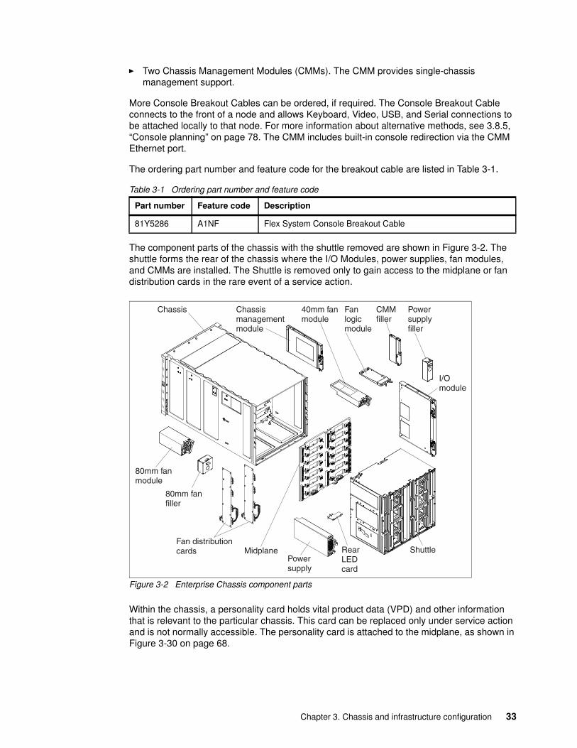
� Two Chassis Management Modules (CMMs). The CMM provides single-chassis management support.
More Console Breakout Cables can be ordered, if required. The Console Breakout Cable connects to the front of a node and allows Keyboard, Video, USB, and Serial connections to be attached locally to that node. For more information about alternative methods, see 3.8.5, “Console planning” on page 78. The CMM includes built-in console redirection via the CMM Ethernet port.
The ordering part number and feature code for the breakout cable are listed in Table 3-1.
Table 3-1 Ordering part number and feature code
The component parts of the chassis with the shuttle removed are shown in Figure 3-2. The shuttle forms the rear of the chassis where the I/O Modules, power supplies, fan modules, and CMMs are installed. The Shuttle is removed only to gain access to the midplane or fan distribution cards in the rare event of a service action.
Figure 3-2 Enterprise Chassis component parts
Within the chassis, a personality card holds vital product data (VPD) and other information that is relevant to the particular chassis. This card can be replaced only under service action and is not normally accessible. The personality card is attached to the midplane, as shown in Figure 3-30 on page 68.
Part number Feature code Description
81Y5286 A1NF Flex System Console Breakout Cable
Chassis Chassismanagementmodule
40mm fanmodule
Fanlogicmodule
CMMfiller
Powersupplyfiller
I/Omodule
ShuttleRearLEDcard
Powersupply
80mm fanfiller
80mm fanmodule
Fan distributioncards Midplane
Chapter 3. Chassis and infrastructure configuration 33
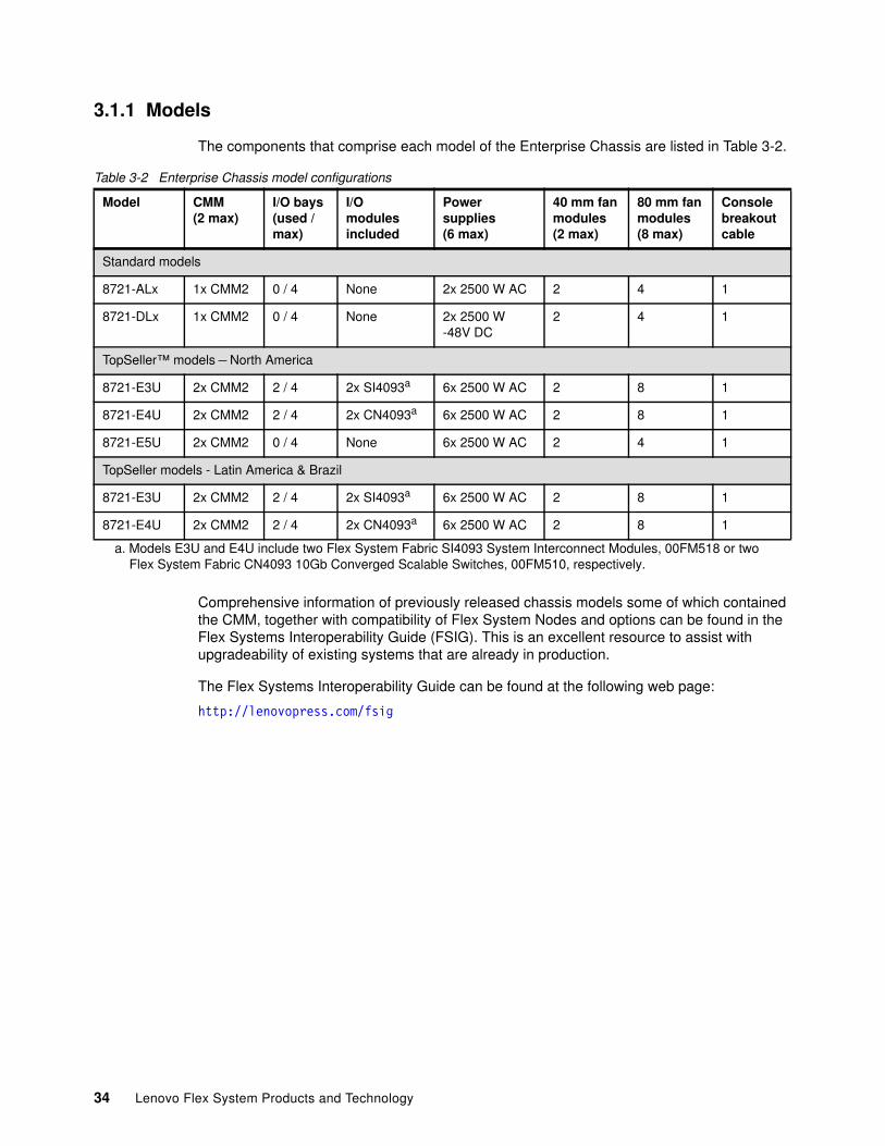
3.1.1 Models
The components that comprise each model of the Enterprise Chassis are listed in Table 3-2.
Table 3-2 Enterprise Chassis model configurations
Comprehensive information of previously released chassis models some of which contained the CMM, together with compatibility of Flex System Nodes and options can be found in the Flex Systems Interoperability Guide (FSIG). This is an excellent resource to assist with upgradeability of existing systems that are already in production.
The Flex Systems Interoperability Guide can be found at the following web page:
http://lenovopress.com/fsig
Model CMM(2 max)
I/O bays(used /max)
I/Omodulesincluded
Powersupplies(6 max)
40 mm fanmodules (2 max)
80 mm fanmodules(8 max)
Consolebreakoutcable
Standard models
8721-ALx 1x CMM2 0 / 4 None 2x 2500 W AC 2 4 1
8721-DLx 1x CMM2 0 / 4 None 2x 2500 W -48V DC
2 4 1
TopSeller™ models – North America
8721-E3U 2x CMM2 2 / 4 2x SI4093a
a. Models E3U and E4U include two Flex System Fabric SI4093 System Interconnect Modules, 00FM518 or two Flex System Fabric CN4093 10Gb Converged Scalable Switches, 00FM510, respectively.
6x 2500 W AC 2 8 1
8721-E4U 2x CMM2 2 / 4 2x CN4093a 6x 2500 W AC 2 8 1
8721-E5U 2x CMM2 0 / 4 None 6x 2500 W AC 2 4 1
TopSeller models - Latin America & Brazil
8721-E3U 2x CMM2 2 / 4 2x SI4093a 6x 2500 W AC 2 8 1
8721-E4U 2x CMM2 2 / 4 2x CN4093a 6x 2500 W AC 2 8 1
34 Lenovo Flex System Products and Technology
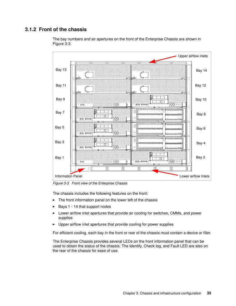
3.1.2 Front of the chassis
The bay numbers and air apertures on the front of the Enterprise Chassis are shown in Figure 3-3.
Figure 3-3 Front view of the Enterprise Chassis
The chassis includes the following features on the front:
� The front information panel on the lower left of the chassis
� Bays 1 - 14 that support nodes
� Lower airflow inlet apertures that provide air cooling for switches, CMMs, and power supplies
� Upper airflow inlet apertures that provide cooling for power supplies
For efficient cooling, each bay in the front or rear of the chassis must contain a device or filler.
The Enterprise Chassis provides several LEDs on the front information panel that can be used to obtain the status of the chassis. The Identify, Check log, and Fault LED are also on the rear of the chassis for ease of use.
aaaaaaaaaaaaaaaaaaaaaaaaaaaaaaaaaaaaaaaaaaaaaaaaaaaaaaaaaaaaaaaaaaaaaaaaaaaaaaaaaaaaaaaaaaaaaaaaaaaaaaaaaaaaaaaaaaaaaaaaaaaaaaaaaaaaaaaaaaaaaaaaaaaaaaaaaaaaaaaaaaaaaaaaaaaaaaaaaaaaaaaaaaaaaaaaaaaaaaaaaaaaaaaaaaaaaaaaaaaaaaaaaaaaaaaaaaaaaaaaaaaaaaaaaaaaaaaaaaaaaaaaaaaaaaaaaaaaaaaaaaaaaaaaaaaaaaaaaaaaaaaaaaaaaaaaaaaaaaaaaaaaaaaaaaaaaaaaaaaaaaaaaaaaaaaaaaaaaaaaaaaaaaaaaaaaaaaaaaaaaaaaaaaaaaaaaaaaaaaaaaaaaaaaaaaaaaaaaaaaaaaaaaaaaaaaaaaaaaaaaaaaaaaaaaaaaaaaaaaaaaaaaaaaaaaaaaaaaaaaaaaaaaaaaaaaaaaaaaaaaaaaaaaaaaaaaaaaaaaaaaaaaaaaaaaaaaaaaaaaaaaaaaaaaaaaaaaaaaaaaaaaaaaaaaaaaaaaaaaaaaaaaaaaaaaaaaaaaaaaaaaaaaaaaaaaaaaaaaaaaaaaaaaaaaaaaaaaaaaaaaaaaaaaaaaaaaaaaaaaaaaaaaaaaaaaaaaaaaaaaaaaaaaaaaaaaaaaaaaaaaaaaaaaaaaaaaaaaaaaaaaaaaaaaaaaaaaaaaaaaaaaaaaaaaaaaaaaaaaaaaaaaaaaaaaaaaaaaaaaaaaaaaaaaaaaa
aaaaaaaaaaaaaaaaaaaaaaaaaaaaaaaaaaaaaaaaaaaaaaaaaaaaaaaaaaaaaaaaaaaaaaaaaaaaaaaaaaaaaaaaaaaaaaaaaaaaaaaaaaaaaaaaaaaaaaaaaaaaaaaaaaaaaaaaaaaaaaaaaaaaaaaaaaaaaaaaaaaaaaaaaaaaaaaaaaaaaaaaaaaaaaaaaaaaaaaaaaaaaaaaaaaaaaaaaaaaaaaaaaaaaaaaaaaaaaaaaaaaaaaaaaaaaaaaaaaaaaaaaaaaaaaaaaaaaaaaaaaaaaaaaaaaaaaaaaaaaaaaaaaaaaaaaaaaaaaaaaaaaaaaaaaaaaaaaaaaaaaaaaaaaaaaaaaaaaaaaaaaaaaaaaaaaaaaaaaaaaaaaaaaaaaaaaaaaaaaaaaaaaaaaaaaaaaaaaaaaaaaaaaaaaaaaaaaaaaaaaaaaaaaaaaaaaaaaaaaaaaaaaaaaaaaaaaaaaaaaaaaaaaaaaaaaaaaaaaaaaaaaaaaaaaaaaaaaaaaaaaaaaaaaaaaaaaaaaaaaaaaaaaaaaaaaaaaaaaaaaaaaaaaaaaaaaaaaaaaaaaaaaaaaaaaaaaaaaaaaaaaaaaaaaaaaaaaaaaaaaaaaaaaaaaaaaaaaaaaaaaaaaaaaaaaaaaaaaaaaaaaaaaaaaaaaaaaaaaaaaaaaaaaaaaaaaaaaaaaaaaaaaaaaaaaaaaaaaaaaaaaaaaaaaaaaaaaaaaaaaaaaaaaaaaaaaaaaaaaaaaaaaaaaaaaaaaaaaaaaaaaaaaaaaaaa
aaaaaaaaaaaaaaaaaaaaaaaaaaaaaaaaaaaaaaaaaaaaaaaaaaaaaaaaaaaaaaaaaaaaaaaaaaaaaaaaaaaaaaaaaaaaaaaaaaaaaaaaaaaaaaaaaaaaaaaaaaaaaaaaaaaaaaaaaaaaaaaaaaaaaaaaaaaaaaaaaaaaaaaaaaaaaaaaaaaaaaaaaaaaaaaaaaaaaaaaaaaaaaaaaaaaaaaaaaaaaaaaaaaaaaaaaaaaaaaaaaaaaaaaaaaaaaaaaaaaaaaaaaaaaaaaaaaaaaaaaaaaaaaaaaaaaaaaaaaaaaaaaaaaaaaaaaaaaaaaaaaaaaaaaaaaaaaaaaaaaaaaaaaaaaaaaaaaaaaaaaaaaaaaaaaaaaaaaaaaaaaaaaaaaaaaaaaaaaaaaaaaaaaaaaaaaaaaaaaaaaaaaaaaaaaaaaaaaaaaaaaaaaaaaaaaaaaaaaaaaaaaaaaaaaaaaaaaaaaaaaaaaaaaaaaaaaaaaaaaaaaaaaaaaaaaaaaaaaaaaaaaaaaaaaaaaaaaaaaaaaaaaaaaaaaaaaaaaaaaaaaaaaaaaaaaaaaaaaaaaaaaaaaaaaaaaaaaaaaaaaaaaaaaaaaaaaaaaaaaaaaaaaaaaaaaaaaaaaaaaaaaaaaaaaaaaaaaaaaaaaaaaaaaaaaaaaaaaaaaaaaaaaaaaaaaaaaaaaaaaaaaaaaaaaaaaaaaaaaaaaaaaaaaaaaaaaaaaaaaaaaaaaaaaaaaaaaaaaaaaaaaaaaaaaaaaaaaaaaaaaaaaaaaaaaaa
aaaaaaaaaaaaaaaaaaaaaaaaaaaaaaaaaaaaaaaaaaaaaaaaaaaaaaaaaaaaaaaaaaaaaaaaaaaaaaaaaaaaaaaaaaaaaaaaaaaaaaaaaaaaaaaaaaaaaaaaaaaaaaaaaaaaaaaaaaaaaaaaaaaaaaaaaaaaaaaaaaaaaaaaaaaaaaaaaaaaaaaaaaaaaaaaaaaaaaaaaaaaaaaaaaaaaaaaaaaaaaaaaaaaaaaaaaaaaaaaaaaaaaaaaaaaaaaaaaaaaaaaaaaaaaaaaaaaaaaaaaaaaaaaaaaaaaaaaaaaaaaaaaaaaaaaaaaaaaaaaaaaaaaaaaaaaaaaaaaaaaaaaaaaaaaaaaaaaaaaaaaaaaaaaaaaaaaaaaaaaaaaaaaaaaaaaaaaaaaaaaaaaaaaaaaaaaaaaaaaaaaaaaaaaaaaaaaaaaaaaaaaaaaaaaaaaaaaaaaaaaaaaaaaaaaaaaaaaaaaaaaaaaaaaaaaaaaaaaaaaaaaaaaaaaaaaaaaaaaaaaaaaaaaaaaaaaaaaaaaaaaaaaaaaaaaaaaaaaaaaaaaaaaaaaaaaaaaaaaaaaaaaaaaaaaaaaaaaaaaaaaaaaaaaaaaaaaaaaaaaaaaaaaaaaaaaaaaaaaaaaaaaaaaaaaaaaaaaaaaaaaaaaaaaaaaaaaaaaaaaaaaaaaaaaaaaaaaaaaaaaaaaaaaaaaaaaaaaaaaaaaaaaaaaaaaaaaaaaaaaaaaaaaaaaaaaaaaaaaaaaaaaaaaaaaaaaaaaaaaaaaaaaaaaaaaa
aaaaaaaaaaaaaaaaaaaaaaaaaaaaaaaaaaaaaaaaaaaaaaaaaaaaaaaaaaaaaaaaaaaaaaaaaaaaaaaaaaaaaaaaaaaaaaaaaaaaaaaaaaaaaaaaaaaaaaaaaaaaaaaaaaaaaaaaaaaaaaaaaaaaaaaaaaaaaaaaaaaaaaaaaaaaaaaaaaaaaaaaaaaaaaaaaaaaaaaaaaaaaaaaaaaaaaaaaaaaaaaaaaaaaaaaaaaaaaaaaaaaaaaaaaaaaaaaaaaaaaaaaaaaaaaaaaaaaaaaaaaaaaaaaaaaaaaaaaaaaaaaaaaaaaaaaaaaaaaaaaaaaaaaaaaaaaaaaaaaaaaaaaaaaaaaaaaaaaaaaaaaaaaaaaaaaaaaaaaaaaaaaaaaaaaaaaaaaaaaaaaaaaaaaaaaaaaaaaaaaaaaaaaaaaaaaaaaaaaaaaaaaaaaaaaaaaaaaaaaaaaaaaaaaaaaaaaaaaaaaaaaaaaaaaaaaaaaaaaaaaaa
aaaaaaaaaaaaaaaaaaaaaaaaaaaaaaaaaaaaaaaaaaaaaaaaaaaaaaaaaaaaaaaaaaaaaaaaaaaaaaaaaaaaaaaaaaaaaaaaaaaaaaaaaaaaaaaaaaaaaaaaaaaaaaaaaaaaaaaaaaaaaaaaaaaaaaaaaaaaaaaaaaa a a a a a a a a
aaaaaaaaaaaaaaaaaaaaaaaaaaaaaaaaaaaaaaaaaaaaaaaaaaaaaaaaaaaaaaaaaaaaaaaaaaaaaaaaaaaaaaaaaaaaaaaaaaaaaaaaaaaaaaaaaaaaaaaaaaaaaaaaaaaaaaaaaaaaaaaaaaaaaaaaaaaaaaaaaaaaaaaaaaaa a a a a a a a a a
aaaaaaaaaaaaaaaaaaaaaaaaaaaaaaaaaaaaaaaaaaaaaaaaaaaaaaaaaaaaaaaaaaaaaaaaaaaaaaaaaaaaaaaaaaaaaaaaaaaaaaaaaaaaaaaaaaaaaaaaaaaaaaaaaaaaaaaaaaaaaaaaaaaaaaaa
aaaaaaaaaaaaaaaaaaaaaaaaaaaaaaaaaaaaaaaaaaaaaaaaaaaaaaaaaaaaaaaaaaaaaaaaaaaaaaaaaaaaaaaaaaaaaaaaaaaaaaaaaaaaaaaaaaaaaaaaaaaaaaaaaaaaaaaaaaaaaaaaaaaaaaaaaaaaaaaaaaaaaaaaaaaaaaaaaaaaaaaaaaaaaaaaaaaaaaaaaaaaaaaaaaaaaaaaaaaaaaaaaaaaaaaaaaaaaaaaaaaaaaaaaaaaaaaaaaaaaaaaaaaaaaaaaaaaaaaaaaaaaaaaaaaaaaaaaaaaaaaaaaaaaaaaaaaaaaaaaaaaaaaaaaaaaaaaaaaaaaaaaaaaaaaaaaaaaaaaaaaaaaaaaaaaaaaaaaaaaaaaaaaaaaaaaaaaaaaaaaaaaaaaaaaaaaaaaaaaaaaaaaaaaaaaaaaaaaaaaaaaaaaaaaaaaaaaaaaaaaaaaaaaaaaaaaaaaaaaaaaaaaaaaaaaaaaaaaaaaaaa
aaaaaaaaaaaaaaaaaaaaaaaaaaaaaaaaaaaaaaaaaaaaaaaaaaaaaaaaaaaaaaaaaaaaaaaaaaaaaaaaaaaaaaaaaaaaaaaaaaaaaaaaaaaaaaaaaaaaaaaaaaaaaaaaaaaaaaaaaaaaaaaaaaaaaaaaaaaaaaaaaaa a a a a a a a a
aaaaaaaaaaaaaaaaaaaaaaaaaaaaaaaaaaaaaaaaaaaaaaaaaaaaaaaaaaaaaaaaaaaaaaaaaaaaaaaaaaaaaaaaaaaaaaaaaaaaaaaaaaaaaaaaaaaaaaaaaaaaaaaaaaaaaaaaaaaaaaaaaaaaaaaaaaaaaaaaaaaaaaaaaaaa a a a a a a a a a
aaaaaaaaaaaaaaaaaaaaaaaaaaaaaaaaaaaaaaaaaaaaaaaaaaaaaaaaaaaaaaaaaaaaaaaaaaaaaaaaaaaaaaaaaaaaaaaaaaaaaaaaaaaaaaaaaaaaaaaaaaaaaaaaaaaaaaaaaaaaaaaaaaaaaaaa
Bay 1
Bay 3
Bay 5
Bay 7
Bay 9
Bay 11
Bay 13 Bay 14
Bay 12
Bay 10
Bay 8
Bay 6
Bay 4
Bay 2
Upper airflow inlets
Lower airflow InletsInformation Panel
Chapter 3. Chassis and infrastructure configuration 35
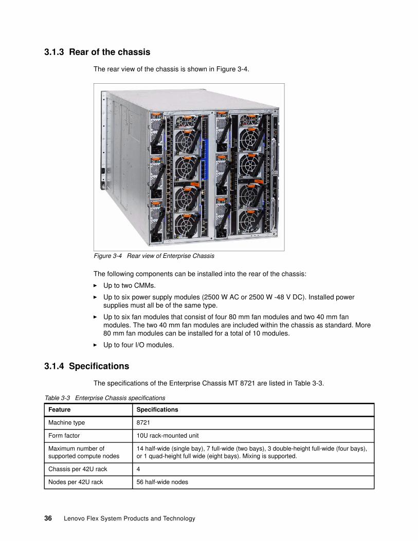
3.1.3 Rear of the chassis
The rear view of the chassis is shown in Figure 3-4.
Figure 3-4 Rear view of Enterprise Chassis
The following components can be installed into the rear of the chassis:
� Up to two CMMs.
� Up to six power supply modules (2500 W AC or 2500 W -48 V DC). Installed power supplies must all be of the same type.
� Up to six fan modules that consist of four 80 mm fan modules and two 40 mm fan modules. The two 40 mm fan modules are included within the chassis as standard. More 80 mm fan modules can be installed for a total of 10 modules.
� Up to four I/O modules.
3.1.4 Specifications
The specifications of the Enterprise Chassis MT 8721 are listed in Table 3-3.
Table 3-3 Enterprise Chassis specifications
Feature Specifications
Machine type 8721
Form factor 10U rack-mounted unit
Maximum number of supported compute nodes
14 half-wide (single bay), 7 full-wide (two bays), 3 double-height full-wide (four bays), or 1 quad-height full wide (eight bays). Mixing is supported.
Chassis per 42U rack 4
Nodes per 42U rack 56 half-wide nodes
36 Lenovo Flex System Products and Technology
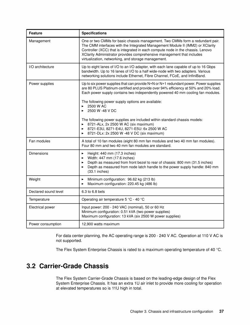
For data center planning, the AC operating range is 200 - 240 V AC. Operation at 110 V AC is not supported.
The Flex System Enterprise Chassis is rated to a maximum operating temperature of 40 °C.
3.2 Carrier-Grade Chassis
The Flex System Carrier-Grade Chassis is based on the leading-edge design of the Flex System Enterprise Chassis. It has an extra 1U air inlet to provide more cooling for operation at elevated temperatures so is 11U high in total.
Management One or two CMMs for basic chassis management. Two CMMs form a redundant pair. The CMM interfaces with the Integrated Management Module II (IMM2) or XClarity Controller (XCC) that is integrated in each compute node in the chassis. Lenovo XClarity Administrator provides comprehensive management that includes virtualization, networking, and storage management.
I/O architecture Up to eight lanes of I/O to an I/O adapter, with each lane capable of up to 16 Gbps bandwidth. Up to 16 lanes of I/O to a half wide-node with two adapters. Various networking solutions include Ethernet, Fibre Channel, FCoE, and InfiniBand.
Power supplies Up to six power supplies that can provide N+N or N+1 redundant power. Power supplies are 80 PLUS Platinum-certified and provide over 94% efficiency at 50% and 20% load. Each power supply contains two independently powered 40 mm cooling fan modules.
The following power supply options are available: � 2500 W AC� 2500 W -48 V DC
The following power supplies are included within standard chassis models: � 8721-ALx, 2x 2500 W AC (six maximum)� 8721-E3U, 8271-E4U, 8271-E5U: 6x 2500 W AC � 8721-DLx: 2x 2500 W -48 V DC (six maximum)
Fan modules A total of 10 fan modules (eight 80 mm fan modules and two 40 mm fan modules).Four 80 mm and two 40 mm fan modules are standard.
Dimensions � Height: 440 mm (17.3 inches)� Width: 447 mm (17.6 inches)� Depth as measured from front bezel to rear of chassis: 800 mm (31.5 inches)� Depth as measured from node latch handle to the power supply handle: 840 mm
(33.1 inches)
Weight � Minimum configuration: 96.62 kg (213 lb)� Maximum configuration: 220.45 kg (486 lb)
Declared sound level 6.3 to 6.8 bels
Temperature Operating air temperature 5 °C - 40 °C
Electrical power Input power: 200 - 240 VAC (nominal), 50 or 60 HzMinimum configuration: 0.51 kVA (two power supplies)Maximum configuration: 13 kVA (six 2500 W power supplies)
Power consumption 12,900 watts maximum
Feature Specifications
Chapter 3. Chassis and infrastructure configuration 37
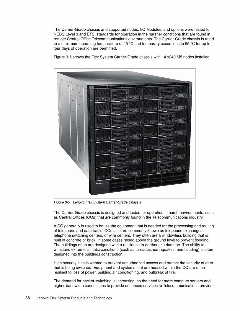
The Carrier-Grade chassis and supported nodes, I/O Modules, and options were tested to NEBS Level 3 and ETSI standards for operation in the harsher conditions that are found in remote Central Office Telecommunications environments. The Carrier-Grade chassis is rated to a maximum operating temperature of 45 °C and temporary excursions to 55 °C for up to four days of operation are permitted.
Figure 3-5 shows the Flex System Carrier-Grade chassis with 14 x240 M5 nodes installed.
Figure 3-5 Lenovo Flex System Carrier-Grade Chassis
The Carrier-Grade chassis is designed and tested for operation in harsh environments, such as Central Offices (COs) that are commonly found in the Telecommunications industry.
A CO generally is used to house the equipment that is needed for the processing and routing of telephone and data traffic. COs also are commonly known as telephone exchanges, telephone switching centers, or wire centers. They often are a windowless building that is built of concrete or brick, in some cases raised above the ground level to prevent flooding. The buildings often are designed with a resilience to earthquake damage. The ability to withstand extreme climatic conditions (such as tornados, earthquakes, and flooding) is often designed into the buildings construction.
High security also is wanted to prevent unauthorized access and protect the security of data that is being switched. Equipment and systems that are housed within the CO are often resilient to loss of power, building air conditioning, and outbreak of fire.
The demand for packet-switching is increasing, so the need for more compute servers and higher-bandwidth connections to provide enhanced services to Telecommunications provider
38 Lenovo Flex System Products and Technology
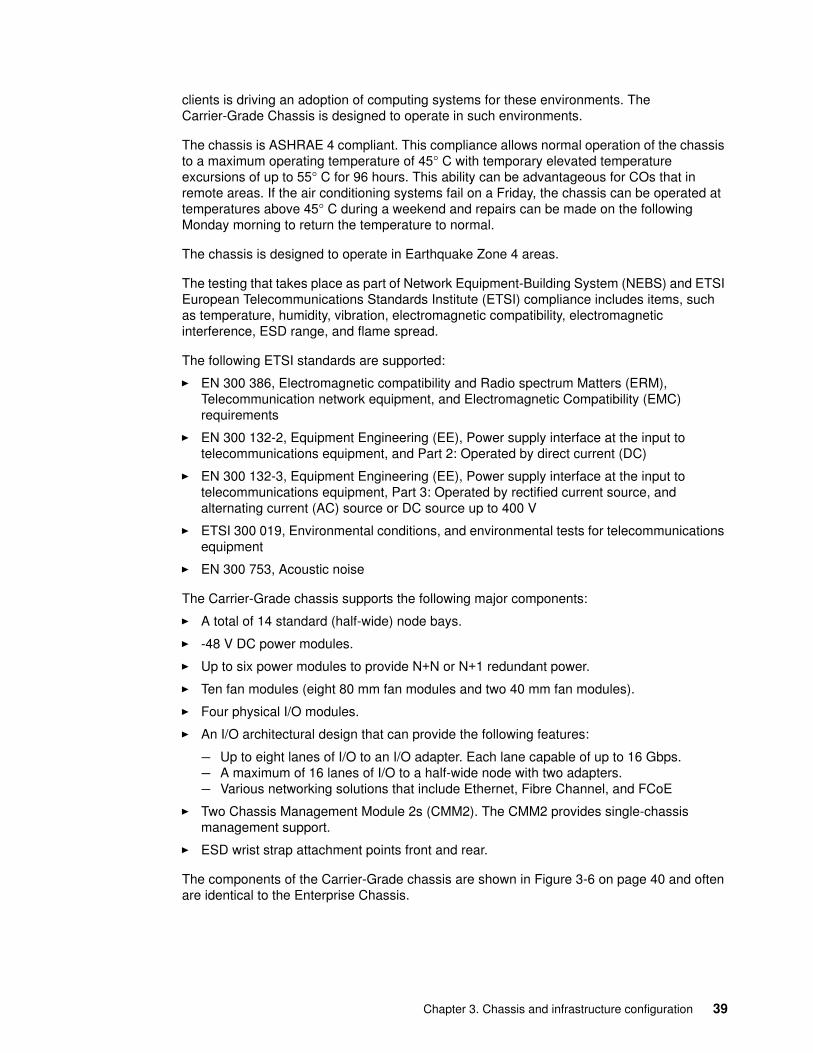
clients is driving an adoption of computing systems for these environments. The Carrier-Grade Chassis is designed to operate in such environments.
The chassis is ASHRAE 4 compliant. This compliance allows normal operation of the chassis to a maximum operating temperature of 45° C with temporary elevated temperature excursions of up to 55° C for 96 hours. This ability can be advantageous for COs that in remote areas. If the air conditioning systems fail on a Friday, the chassis can be operated at temperatures above 45° C during a weekend and repairs can be made on the following Monday morning to return the temperature to normal.
The chassis is designed to operate in Earthquake Zone 4 areas.
The testing that takes place as part of Network Equipment-Building System (NEBS) and ETSI European Telecommunications Standards Institute (ETSI) compliance includes items, such as temperature, humidity, vibration, electromagnetic compatibility, electromagnetic interference, ESD range, and flame spread.
The following ETSI standards are supported:
� EN 300 386, Electromagnetic compatibility and Radio spectrum Matters (ERM), Telecommunication network equipment, and Electromagnetic Compatibility (EMC) requirements
� EN 300 132-2, Equipment Engineering (EE), Power supply interface at the input to telecommunications equipment, and Part 2: Operated by direct current (DC)
� EN 300 132-3, Equipment Engineering (EE), Power supply interface at the input to telecommunications equipment, Part 3: Operated by rectified current source, and alternating current (AC) source or DC source up to 400 V
� ETSI 300 019, Environmental conditions, and environmental tests for telecommunications equipment
� EN 300 753, Acoustic noise
The Carrier-Grade chassis supports the following major components:
� A total of 14 standard (half-wide) node bays.
� -48 V DC power modules.
� Up to six power modules to provide N+N or N+1 redundant power.
� Ten fan modules (eight 80 mm fan modules and two 40 mm fan modules).
� Four physical I/O modules.
� An I/O architectural design that can provide the following features:
– Up to eight lanes of I/O to an I/O adapter. Each lane capable of up to 16 Gbps.– A maximum of 16 lanes of I/O to a half-wide node with two adapters.– Various networking solutions that include Ethernet, Fibre Channel, and FCoE
� Two Chassis Management Module 2s (CMM2). The CMM2 provides single-chassis management support.
� ESD wrist strap attachment points front and rear.
The components of the Carrier-Grade chassis are shown in Figure 3-6 on page 40 and often are identical to the Enterprise Chassis.
Chapter 3. Chassis and infrastructure configuration 39
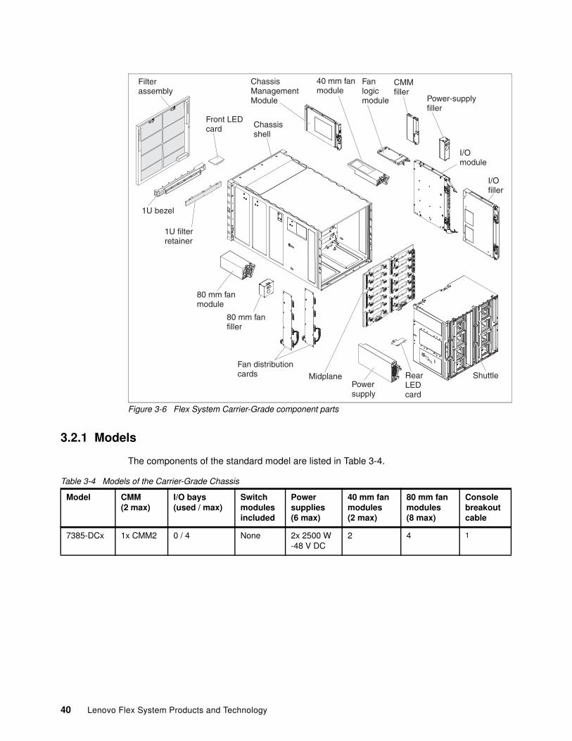
Figure 3-6 Flex System Carrier-Grade component parts
3.2.1 Models
The components of the standard model are listed in Table 3-4.
Table 3-4 Models of the Carrier-Grade Chassis
Chassisshell
ChassisManagementModule
40 mm fanmodule
Fanlogicmodule
CMMfiller
Power-supplyfiller
I/Omodule
ShuttleRearLEDcard
Powersupply
80 mm fanfiller
80 mm fanmodule
Fan distributioncards Midplane
I/Ofiller
Filterassembly
Front LEDcard
1U bezel
1U filterretainer
Model CMM(2 max)
I/O bays(used / max)
Switchmodulesincluded
Powersupplies(6 max)
40 mm fanmodules (2 max)
80 mm fanmodules(8 max)
Consolebreakoutcable
7385-DCx 1x CMM2 0 / 4 None 2x 2500 W-48 V DC
2 4 1
40 Lenovo Flex System Products and Technology
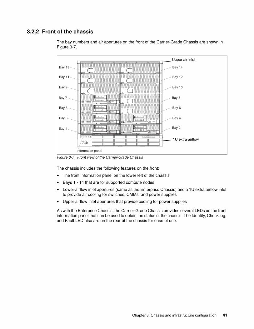
3.2.2 Front of the chassis
The bay numbers and air apertures on the front of the Carrier-Grade Chassis are shown in Figure 3-7.
Figure 3-7 Front view of the Carrier-Grade Chassis
The chassis includes the following features on the front:
� The front information panel on the lower left of the chassis
� Bays 1 - 14 that are for supported compute nodes
� Lower airflow inlet apertures (same as the Enterprise Chassis) and a 1U extra airflow inlet to provide air cooling for switches, CMMs, and power supplies
� Upper airflow inlet apertures that provide cooling for power supplies
As with the Enterprise Chassis, the Carrier-Grade Chassis provides several LEDs on the front information panel that can be used to obtain the status of the chassis. The Identify, Check log, and Fault LED also are on the rear of the chassis for ease of use.
aaaaaaaaaaaaaaaaaaaaaaaaaaaaaaaaaaaaaaaaaaaaaaaaaaaaaaaaaaaaaaaaaaaaaaaaaaaaaaaaaaaaaaaaaaaaaaaaaaaaaaaaaaaaaaaaaaaaaaaa
aaaaaaaaaaaaaaaaaaaaaaaaaaaaaaaaaaaaaaaaaaaaaaaaaaaaaaaaaaaaaaaaaaaaaaaaaaaaaaaaaaaaaaaaaaaaaaaaa a a a a a a a
aaaaaaaaaaaaaaaaaaaaaaaaaaaaaaaaaaaaaaaaaaaaaaaaaaaaaaaaaaaaaaaaaaaaaaaaaaaaaaaaaaaaaaaaaaaaaaaaaaaaaaaaaaaaaaaaaaaaaaaaaaaaaaaaaaaaaaaaaaaaaaaaaaaaaaaaaaaaaaaaaaaaaaaaaaaaaaaaaaaaaaaaaaaaaaaaaaaaaaaaaaaaaaaaaaaaaaaaaaaaaaaaaaaaaaaaaaaaaaaaaaaaaaaaaaaaaaaaaaaaaaaaaaaaaaaaaaaaaaaaaaaaaaaaaaaaaaaaaaaaaaaaaaaaaaaaaaaaaaaaaaaaaaaaaaaaaaaaaaaaaaaaaaaaaaaaaaaaaaaaaaaaaaaaaaaaaaaaaaaaaaaaaaaaaaaaaaaaaaaaaaaaaaaaaaaaaaaaaaaaaaaaaaaaaaaaaaaaaaaaaaaaaaaaaaaaaaaaaaaaaaaaaaaaaaaaaaaaaaaaaaaaaaaaaaaaaaaaaaaaaaaaaaaaaaaaaaaaaaaaaaaaaaaaaaaaaaaaaaaaaaaaaaaaaa
aaaaaaaaaaaaaaaaaaaaaaaaaaaaaaaaaaaaaaaaaaaaaaaaaaaaaaaaaaaaaaaaaaaaaaaaaaaaaaaaaaaaaaaaaaaaaaaaaaaaaaaaaaaaaaaaaaaaaaaaaaaaaaaaaaaaaaaaaaaaaaaaaaaaaaaaaaaaaaaaaaaaaaaaaaaaaaaaaaaaaaaaaaaaaaaaaaaaaaaaaaaaaaaaaaaaaaaaaaaaaaaaaaaaaaaaaaaaaaaaaaaaaaaaaaaaaaaaaaaaaaaaaaaaaaaaaaaaaaaaaaaaaaaaaaaaaaaaaaaaaaaaaaaaaaaaaaaaaaaaaaaaaaaaaaaaaaaaaaaaaaaaaaaaaaaaaaaaaaaaaaaaaaaaaaaaaaaaaaaaaaaaaaaaaaaaaaaaaaaaaaaaaaaaaaaaaaaaaaaaaaaaaaaaaaaaaaaaaaaaaaaaaaaaaaaaaaaaaaaaaaaaaaaaaaaaaaaaaaaaaaaaaaaaaaaaaaaaaaaaaaaaaaaaaaaaaaaaaaaaaaaaaaaaaaaaaaaaaaaaaaaaaaaaaa
aaaaaaaaaaaaaaaaaaaaaaaaaaaaaaaaaaaaaaaaaaaaaaaaaaaaaaaaaaaaaaaaaaaaaaaaaaaaaaaaaaaaaaaaaaaaaaaaaaaaaaaaaaaaaaaaaaaaaaaaaaaaaaaaaaaaaaaaaaaaaaaaaaaaaaaaaaaaaaaaaaaaaaaaaaaaaaaaaaaaaaaaaaaaaaaaaaaaaaaaaaaaaaaaaaaaaaaaaaaaaaaaaaaaaaaaaaaaaaaaaaaaaaaaaaaaaaaaaaaaaaaaaaaaaaaaaaaaaaaaaaaaaaaaaaaaaaaaaaaaaaaaaaaaaaaaaaaaaaaaaaaaaaaaaaaaaaaaaaaaaaaaaaaaaaaaaaaaaaaaaaaaaaaaaaaaaaaaaaaaaaaaaaaaaaaaaaaaaaaaaaaaaaaaaaaaaaaaaaaaaaaaaaaaaaaaaaaaaaaaaaaaaaaaaaaaaaaaaaaaaaaaaaaaaaaaaaaaaaaaaaaaaaaaaaaaaaaaaaaaaaaaaaaaaaaaaaaaaaaaaaaaaaaaaaaaaaaaaaaaaaaaaaaaaa
aaaaaaaaaaaaaaaaaaaaaaaaaaaaaaaaaaaaaaaaaaaaaaaaaaaaaaaaaaaaaaaaaaaaaaaaaaaaaaaaaaaaaaaaaaaaaaaaaaaaaaaaaaaaaaaaaaaaaaaaaaaaaaaaaaaaaaaaaaaaaaaaaaaaaaaaaaaaaaaaaaaaaaaaaaaaaaaaaaaaaaaaaaaaaaaaaaaaaaaaaaaaaaaaaaaaaaaaaaaaaaaaaaaaaaaaaaaaaaaaaaaaaaaaaaaaaaaaaaaaaaaaaaaaaaaaaaaaaaaaaaaaaaaaaaaaaaaaaaaaaaaaaaaaaaaaaaaaaaaaaaaaaaaaaaaaaaaaaaaaaaaaaaaaaaaaaaaaaaaaaaaaaaaaaaaaaaaaaaaaaaaaaaaaaaaaaaaaaaaaaaaaaaaaaaaaaaaaaaaaaaaaaaaaaaaaaaaaaaaaaaaaaaaaaaaaaaaaaaaaaaaaaaaaaaaaaaaaaaaaaaaaaaaaaaaaaaaaaaaaaaaaaaaaaaaaaaaaaaaaaaaaaaaaaaaaaaaaaaaaaaaaaaaaaa
aaaaaaaaaaaaaaaaaaaaaaaaaaaaaaaaaaaaaaaaaaaaaaaaaaaaaaaaaaaaaaaaaaaaaaaaaaaaaaaaaaaaaaaaaaaaaaaaaaaaaaaaaaaaaaaaaaaaaaaa
aaaaaaaaaaaaaaaaaaaaaaaaaaaaaaaaaaaaaaaaaaaaaaaaaaaaaaaaaaaaaaaaaaaaaaaaaaaaaaaaaaaaaaaaaaaaaaaaa a a a a a a a
aaaaaaaaaaaaaaaaaaaaaaaaaaaaaaaaaaaaaaaaaaaaaaaaaaaaaaaaaaaaaaaaaaaaaaaaaaaaaaaaaaaaaaaaaaaaaaaaaaaaaaaaaaaaaaaaaaaaaaaa
aaaaaaaaaaaaaaaaaaaaaaaaaaaaaaaaaaaaaaaaaaaaaaaaaaaaaaaaaaaaaaaaaaaaaaaaaaaaaaaaaaaaaaaaaaaaaaaaa a a a a a a a
aaaaaaaaaaaaaaaaaaaaaaaaaaaaaaaaaaaaaaaaaaaaaaaaaaaaaaaaaaaaaaaaaaaaaaaaaaaaaaaaaaaaaaaaaaaaaaaaaaaaaaaaaaaaaaaaaaaaaaaa
aaaaaaaaaaaaaaaaaaaaaaaaaaaaaaaaaaaaaaaaaaaaaaaaaaaaaaaaaaaaaaaaaaaaaaaaaaaaaaaaaaaaaaaaaaaaaaaaa a a a a a a a
Bay 1
Bay 5
Bay 3
Bay 7
Bay 11
Bay 9
Bay 13
Bay 2
Bay 6
Bay 4
Bay 8
Bay 12
Bay 10
Bay 14
Information panel
!
aaaaaaaaaaaaaaaaaaaaaaaaaaaaaaaaaaaaaaaaaaaaaaaaaaaaaaaaaaaaaaaaaaaaaaaaaaaaaaaaaaaaaaaaaaaaaaaaaaaaaaaaaaaaaaaaaaaaaaaaaaaaaaaaaaaaaaaaaaaaaaaaaaaaaaaaaaaaaaaaaaaaaaaaaaaaaaaaaaaaaaaaaaaaaaaaaaaaaaaaaaaaaaaaaaaaaaaaaaaaaaaaaaaaaaaaaaaaaaaaaaaaaaaaaaaaaaaaaaaaaaaaaaaaaaaaaaaaaaaaaaaaaaaaaaaaaaaaaaaaaaaaaaaaaaaaaaaaaaaaaaaaaaaaaaaaaaaaaaaaaaaaaaaaaaaaaaaaaaaaaaaaaaaaaaaaaaaaaaaaaaaaaaaaaaaaaaaaaaaaaaaaaaaaaaaaaaaaaaaaaaaaaaaaaaaaaaaaaaaaaaaaaaaaaaaaaaaaaaaaaaaaaaaaaaaaaaaaaaaaaaaaaaaaaaaaaaaaaaaaaaaaaaaaaaaaaaaaaaaaaaaaaaaaaaaaaaaaaaaaaaaaaaaaaa
aaaaaaaaaaaaaaaaaaaaaaaaaaaaaaaaaaaaaaaaaaaaaaaaaaaaaaaaaaaaaaaaaaaaaaaaaaaaaaaaaaaaaaaaaaaaaaaaaaaaaaaaaaaaaaaaaaaaaaaaaaaaaaaaaaaaaaaaaaaaaaaaaaaaaaaaaaaaaaaaaaaaaaaaaaaaaaaaaaaaaaaaaaaaaaaaaaaaaaaaaaaaaaaaaaaaaaaaaaaaaaaaaaaaaaaaaaaaaaaaaaaaaaaaaaaaaaaaaaaaaaaaaaaaaaaaaaaaaaaaaaaaaaaaaaaaaaaaaaaaaaaaaaaaaaaaaaaaaaaaaaaaaaaaaaaaaaaaaaaaaaaaaaaaaaaaaaaaaaaaaaaaaaaaaaaaaaaaaaaaaaaaaaaaaaaaaaaaaaaaaaaaaaaaaaaaaaaaaaaaaaaaaaaaaaaaaaaaaaaaaaaaaaaaaaaaaaaaaaaaaaaaaaaaaaaaaaaaaaaaaaaaaaaaaaaaaaaaaaaaaaaaaaaaaaaaaaaaaaaaaaaaaaaaaaaaaaaaaaaaaaaaaaaaaa
aaaaaaaaaaaaaaaaaaaaaaaaaaaaaaaaaaaaaaaaaaaaaaaaaaaaaaaaaaaaaaaaaaaaaaaaaaaaaaaaaaaaaaaaaaaaaaaaaaaaaaaaaaaaaaaaaaaaaaaaaaaaaaaaaaaaaaaaaaaaaaaaaaaaaaaaaaaaaaaaaaaaaaaaaaaaaaaaaaaaaaaaaaaaaaaaaaaaaaaaaaaaaaaaaaaaaaaaaaaaaaaaaaaaaaaaaaaaaaaaaaaaaaaaaaaaaaaaaaaaaaaaaaaaaaaaaaaaaaaaaaaaaaaaaaaaaaaaaaaaaaaaaaaaaaaaaaaaaaaaaaaaaaaaaaaaaaaaaaaaaaaaaaaaaaaaaaaaaaaaaaaaaaaaaaaaaaaaaaaaaaaaaaaaaaaaaaaaaaaaaaaaaaaaaaaaaaaaaaaaaaaaaaaaaaaaaaaaaaaaaaaaaaaaaaaaaaaaaaaaaaaaaaaaaaaaaaaaaaaaaaaaaaaaaaaaaaaaaaaaa a a a a a a a a a a a a a a a a a a a a a a a a
aaaaaaaaaaaaaaaaaaaaaaaaaaaaaaaaaaaaaaaaaaaaaaaaaaaaaaaaaaaaaaaaaaaaaaaaaaaaaaaaaaaaaaaaaaaaaaaaaaaaaaaaaaaaaaaaaaaaaaaa
aaaaaaaaaaaaaaaaaaaaaaaaaaaaaaaaaaaaaaaaaaaaaaaaaaaaaaaaaaaaaaaaaaaaaaaaaaaaaaaaaaaaaaaaaaaaaaaaa a a a a a a a
aaaaaaaaaaaaaaaaaaaaaaaaaaaaaaaaaaaaaaaaaaaaaaaaaaaaaaaaaaaaaaaaaaaaaaaaaaaaaaaaaaaaaaaaaaaaaaaaaaaaaaaaaaaaaaaaaaaaaaaaaaaaaaaaaaaaaaaaaaaaaaaaaaaaaaaaaaaaaaaaaaaaaaaaaaaaaaaaaaaaaaaaaaaaaaaaaaaaaaaaaaaaaaaaaaaaaaaaaaaaaaaaaaaaaaaaaaaaaaaaaaaaaaaaaaaaaaaaaaaaaaaaaaaaaaaaaaaaaaaaaaaaaaaaaaaaaaaaaaaaaaaaaaaaaaaaaaaaaaaaaaaaaaaaaaaaaaaaaaaaaaaaaaaaaaaaaaaaaaaaaaaaaaaaaaaaaaaaaaaaaaaaaaaaaaaaaaaaaaaaaaaaaaaaaaaaaaaaaaaaaaaaaaaaaaaaaaaaaaaaaaaaaaaaaaaaaaaaaaaaaaaaaaaaaaaaaaaaaaaaaaaaaaaaaaaaaaaaaaaaaaaaaaaaaaaaaaaaaaaaaaaaaaaaaaaaaaaaaaaaaaaaaaaaaa
aaaaaaaaaaaaaaaaaaaaaaaaaaaaaaaaaaaaaaaaaaaaaaaaaaaaaaaaaaaaaaaaaaaaaaaaaaaaaaaaaaaaaaaaaaaaaaaaaaaaaaaaaaaaaaaaaaaaaaaa
aaaaaaaaaaaaaaaaaaaaaaaaaaaaaaaaaaaaaaaaaaaaaaaaaaaaaaaaaaaaaaaaaaaaaaaaaaaaaaaaaaaaaaaaaaaaaaaaa a a a a a a a
Flex Carrier-GradeSystem
ESD1U extra airflow
Upper air inlet
Chapter 3. Chassis and infrastructure configuration 41
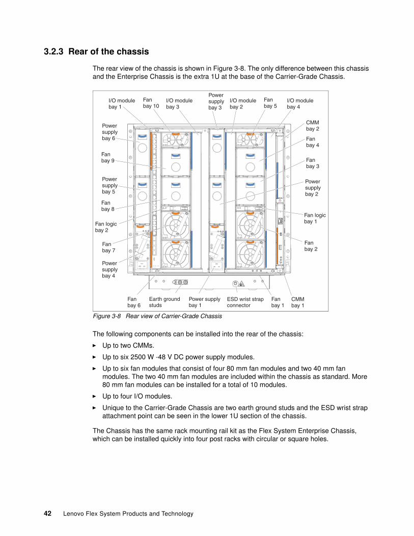
3.2.3 Rear of the chassis
The rear view of the chassis is shown in Figure 3-8. The only difference between this chassis and the Enterprise Chassis is the extra 1U at the base of the Carrier-Grade Chassis.
Figure 3-8 Rear view of Carrier-Grade Chassis
The following components can be installed into the rear of the chassis:
� Up to two CMMs.
� Up to six 2500 W -48 V DC power supply modules.
� Up to six fan modules that consist of four 80 mm fan modules and two 40 mm fan modules. The two 40 mm fan modules are included within the chassis as standard. More 80 mm fan modules can be installed for a total of 10 modules.
� Up to four I/O modules.
� Unique to the Carrier-Grade Chassis are two earth ground studs and the ESD wrist strap attachment point can be seen in the lower 1U section of the chassis.
The Chassis has the same rack mounting rail kit as the Flex System Enterprise Chassis, which can be installed quickly into four post racks with circular or square holes.
Powersupplybay 6
Powersupplybay 5
Powersupplybay 4
Fanbay 10
Fanbay 9
Fanbay 8
Fanbay 7
Fanbay 6
Fan logicbay 2
I/O modulebay 1
Power supplybay 1
I/O modulebay 3
Powersupplybay 3
I/O modulebay 2
Fanbay 5
I/O modulebay 4
CMMbay 2
Powersupplybay 2
Fanbay 4
Fanbay 3
Fan logicbay 1
Fanbay 2
Fanbay 1
CMMbay 1
ESD
ESD wrist strapconnector
Earth groundstuds
42 Lenovo Flex System Products and Technology
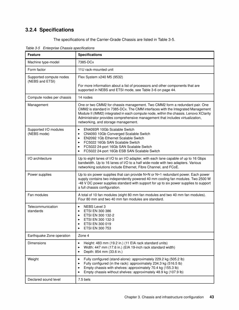
3.2.4 Specifications
The specifications of the Carrier-Grade Chassis are listed in Table 3-5.
Table 3-5 Enterprise Chassis specifications
Feature Specifications
Machine type-model 7385-DCx
Form factor 11U rack-mounted unit
Supported compute nodes (NEBS and ETSI)
Flex System x240 M5 (9532)
For more information about a list of processors and other components that are supported in NEBS and ETSI mode, see Table 3-6 on page 44.
Compute nodes per chassis 14 nodes
Management One or two CMM2 for chassis management. Two CMM2 form a redundant pair. One CMM2 is standard in 7385-DCx. The CMM interfaces with the Integrated Management Module II (IMM2) integrated in each compute node, within the chassis. Lenovo XClarity Administrator provides comprehensive management that includes virtualization, networking, and storage management.
Supported I/O modules (NEBS mode)
� EN4093R 10Gb Scalable Switch� CN4093 10Gb Converged Scalable Switch� EN2092 1Gb Ethernet Scalable Switch� FC5022 16Gb SAN Scalable Switch� FC5022 24-port 16Gb SAN Scalable Switch� FC5022 24-port 16Gb ESB SAN Scalable Switch
I/O architecture Up to eight lanes of I/O to an I/O adapter, with each lane capable of up to 16 Gbps bandwidth. Up to 16 lanes of I/O to a half wide-node with two adapters. Various networking solutions include Ethernet, Fibre Channel, and FCoE.
Power supplies Up to six power supplies that can provide N+N or N+1 redundant power. Each power supply contains two independently powered 40 mm cooling fan modules. Two 2500 W -48 V DC power supplies standard with support for up to six power supplies to support a full chassis configuration.
Fan modules A total of 10 fan modules (eight 80 mm fan modules and two 40 mm fan modules).Four 80 mm and two 40 mm fan modules are standard.
Telecommunication standards
� NEBS Level 3� ETSI EN 300 386� ETSI EN 300 132-2� ETSI EN 300 132-3� ETSI EN 300 019� ETSI EN 300 753
Earthquake Zone operation Zone 4
Dimensions � Height: 483 mm (19.2 in.) (11 EIA rack standard units)� Width: 447 mm (17.6 in.) (EIA 19-inch rack standard width)� Depth: 854 mm (33.6 in.)
Weight � Fully configured (stand-alone): approximately 229.2 kg (505.2 lb)� Fully configured (in the rack): approximately 234.3 kg (516.5 lb)� Empty chassis with shelves: approximately 70.4 kg (155.3 lb)� Empty chassis without shelves: approximately 48.9 kg (107.9 lb)
Declared sound level 7.5 bels
Chapter 3. Chassis and infrastructure configuration 43
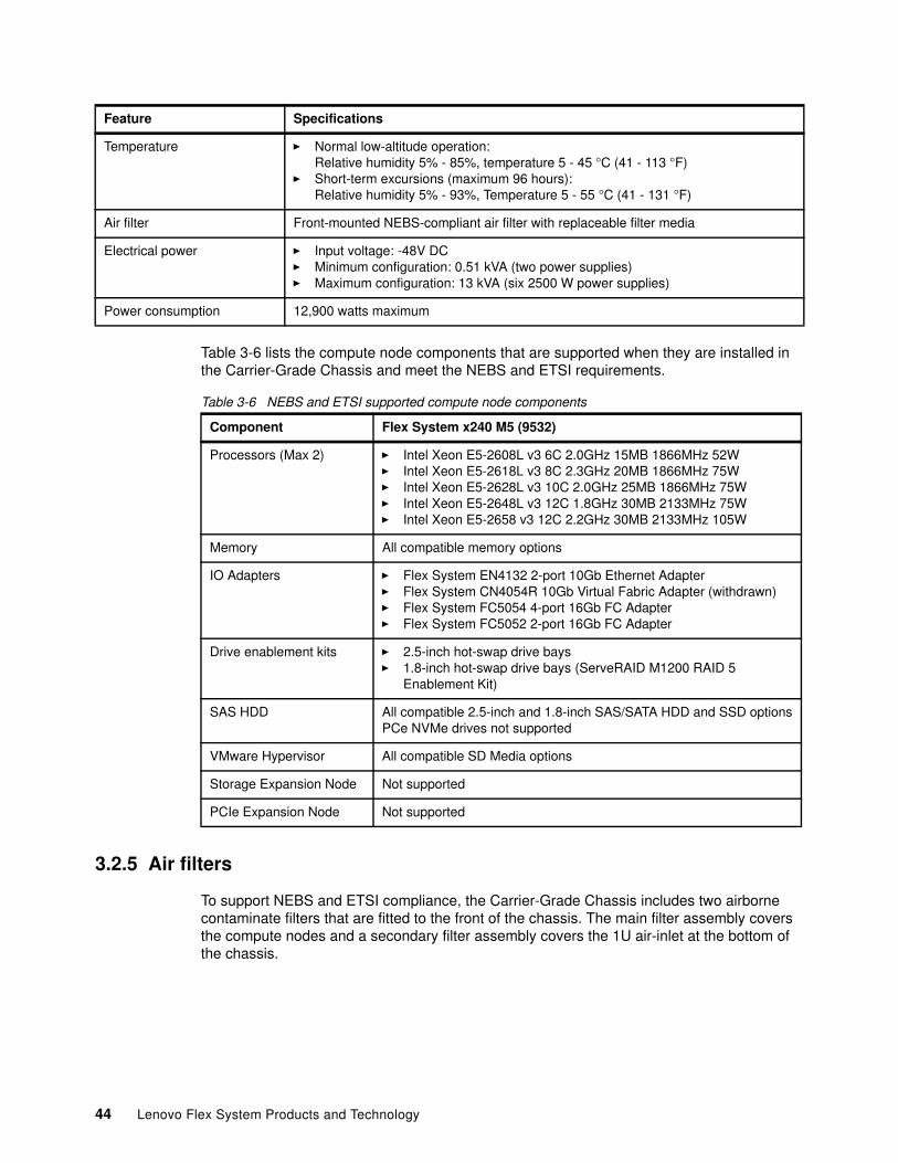
Table 3-6 lists the compute node components that are supported when they are installed in the Carrier-Grade Chassis and meet the NEBS and ETSI requirements.
Table 3-6 NEBS and ETSI supported compute node components
3.2.5 Air filters
To support NEBS and ETSI compliance, the Carrier-Grade Chassis includes two airborne contaminate filters that are fitted to the front of the chassis. The main filter assembly covers the compute nodes and a secondary filter assembly covers the 1U air-inlet at the bottom of the chassis.
Temperature � Normal low-altitude operation:Relative humidity 5% - 85%, temperature 5 - 45 °C (41 - 113 °F)
� Short-term excursions (maximum 96 hours): Relative humidity 5% - 93%, Temperature 5 - 55 °C (41 - 131 °F)
Air filter Front-mounted NEBS-compliant air filter with replaceable filter media
Electrical power � Input voltage: -48V DC� Minimum configuration: 0.51 kVA (two power supplies)� Maximum configuration: 13 kVA (six 2500 W power supplies)
Power consumption 12,900 watts maximum
Feature Specifications
Component Flex System x240 M5 (9532)
Processors (Max 2) � Intel Xeon E5-2608L v3 6C 2.0GHz 15MB 1866MHz 52W� Intel Xeon E5-2618L v3 8C 2.3GHz 20MB 1866MHz 75W� Intel Xeon E5-2628L v3 10C 2.0GHz 25MB 1866MHz 75W� Intel Xeon E5-2648L v3 12C 1.8GHz 30MB 2133MHz 75W� Intel Xeon E5-2658 v3 12C 2.2GHz 30MB 2133MHz 105W
Memory All compatible memory options
IO Adapters � Flex System EN4132 2-port 10Gb Ethernet Adapter� Flex System CN4054R 10Gb Virtual Fabric Adapter (withdrawn)� Flex System FC5054 4-port 16Gb FC Adapter� Flex System FC5052 2-port 16Gb FC Adapter
Drive enablement kits � 2.5-inch hot-swap drive bays� 1.8-inch hot-swap drive bays (ServeRAID M1200 RAID 5
Enablement Kit)
SAS HDD All compatible 2.5-inch and 1.8-inch SAS/SATA HDD and SSD optionsPCe NVMe drives not supported
VMware Hypervisor All compatible SD Media options
Storage Expansion Node Not supported
PCIe Expansion Node Not supported
44 Lenovo Flex System Products and Technology
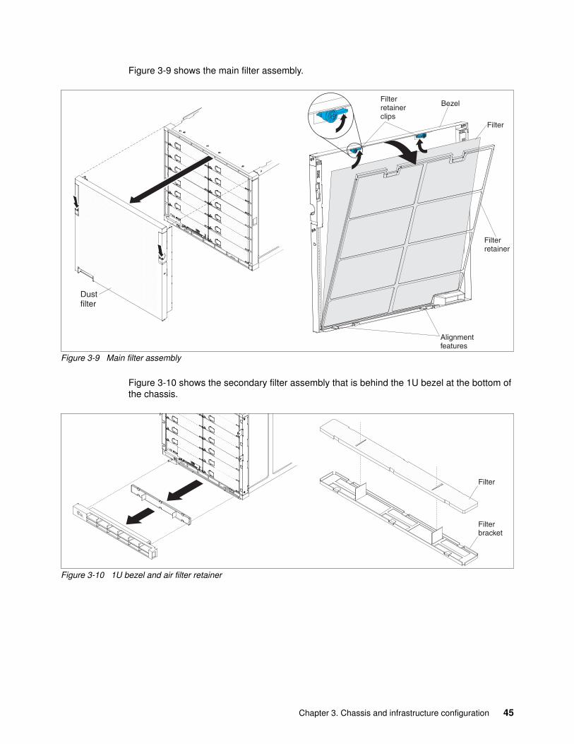
Figure 3-9 shows the main filter assembly.
Figure 3-9 Main filter assembly
Figure 3-10 shows the secondary filter assembly that is behind the 1U bezel at the bottom of the chassis.
Figure 3-10 1U bezel and air filter retainer
Filter
Alignmentfeatures
Filterretainerclips
Filterretainer
Bezel
Filter
Filterbracket
Chapter 3. Chassis and infrastructure configuration 45
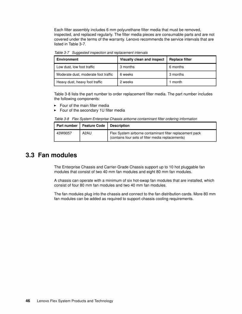
Each filter assembly includes 6 mm polyurethane filter media that must be removed, inspected, and replaced regularly. The filter media pieces are consumable parts and are not covered under the terms of the warranty. Lenovo recommends the service intervals that are listed in Table 3-7.
Table 3-7 Suggested inspection and replacement intervals
Table 3-8 lists the part number to order replacement filter media. The part number includes the following components:
� Four of the main filter media� Four of the secondary 1U filter media
Table 3-8 Flex System Enterprise Chassis airborne contaminant filter ordering information
3.3 Fan modules
The Enterprise Chassis and Carrier-Grade Chassis support up to 10 hot pluggable fan modules that consist of two 40 mm fan modules and eight 80 mm fan modules.
A chassis can operate with a minimum of six hot-swap fan modules that are installed, which consist of four 80 mm fan modules and two 40 mm fan modules.
The fan modules plug into the chassis and connect to the fan distribution cards. More 80 mm fan modules can be added as required to support chassis cooling requirements.
Environment Visually clean and inspect Replace filter
Low dust, low foot traffic 3 months 6 months
Moderate dust, moderate foot traffic 6 weeks 3 months
Heavy dust, heavy foot traffic 2 weeks 1 month
Part number Feature Code Description
43W9057 A2AU Flex System airborne contaminant filter replacement pack(contains four sets of filter media replacements)
46 Lenovo Flex System Products and Technology
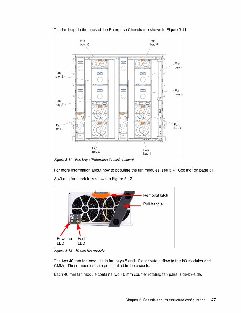
The fan bays in the back of the Enterprise Chassis are shown in Figure 3-11.
Figure 3-11 Fan bays (Enterprise Chassis shown)
For more information about how to populate the fan modules, see 3.4, “Cooling” on page 51.
A 40 mm fan module is shown in Figure 3-12.
Figure 3-12 40 mm fan module
The two 40 mm fan modules in fan bays 5 and 10 distribute airflow to the I/O modules and CMMs. These modules ship preinstalled in the chassis.
Each 40 mm fan module contains two 40 mm counter rotating fan pairs, side-by-side.
Fanbay 10
Fanbay 9
Fanbay 8
Fanbay 7
Fanbay 6
Fanbay 5
Fanbay 4
Fanbay 3
Fanbay 2
Fanbay 1
Power on LED
Fault LED
Removal latch
Pull handle
Chapter 3. Chassis and infrastructure configuration 47
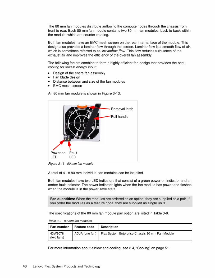
The 80 mm fan modules distribute airflow to the compute nodes through the chassis from front to rear. Each 80 mm fan module contains two 80 mm fan modules, back-to-back within the module, which are counter-rotating.
Both fan modules have an EMC mesh screen on the rear internal face of the module. This design also provides a laminar flow through the screen. Laminar flow is a smooth flow of air, which is sometimes referred to as streamline flow. This flow reduces turbulence of the exhaust air and improves the efficiency of the overall fan assembly.
The following factors combine to form a highly efficient fan design that provides the best cooling for lowest energy input:
� Design of the entire fan assembly� Fan blade design� Distance between and size of the fan modules� EMC mesh screen
An 80 mm fan module is shown in Figure 3-13.
Figure 3-13 80 mm fan module
A total of 4 - 8 80 mm individual fan modules can be installed.
Both fan modules have two LED indicators that consist of a green power-on indicator and an amber fault indicator. The power indicator lights when the fan module has power and flashes when the module is in the power save state.
The specifications of the 80 mm fan module pair option are listed in Table 3-9.
Table 3-9 80 mm fan modules
For more information about airflow and cooling, see 3.4, “Cooling” on page 51.
Fan quantities: When the modules are ordered as an option, they are supplied as a pair. If you order the modules as a feature code, they are supplied as single units.
Part number Feature code Description
43W9078(two fans)
A0UA (one fan) Flex System Enterprise Chassis 80 mm Fan Module
Power on LED
Fault LED
Removal latch
Pull handle
48 Lenovo Flex System Products and Technology
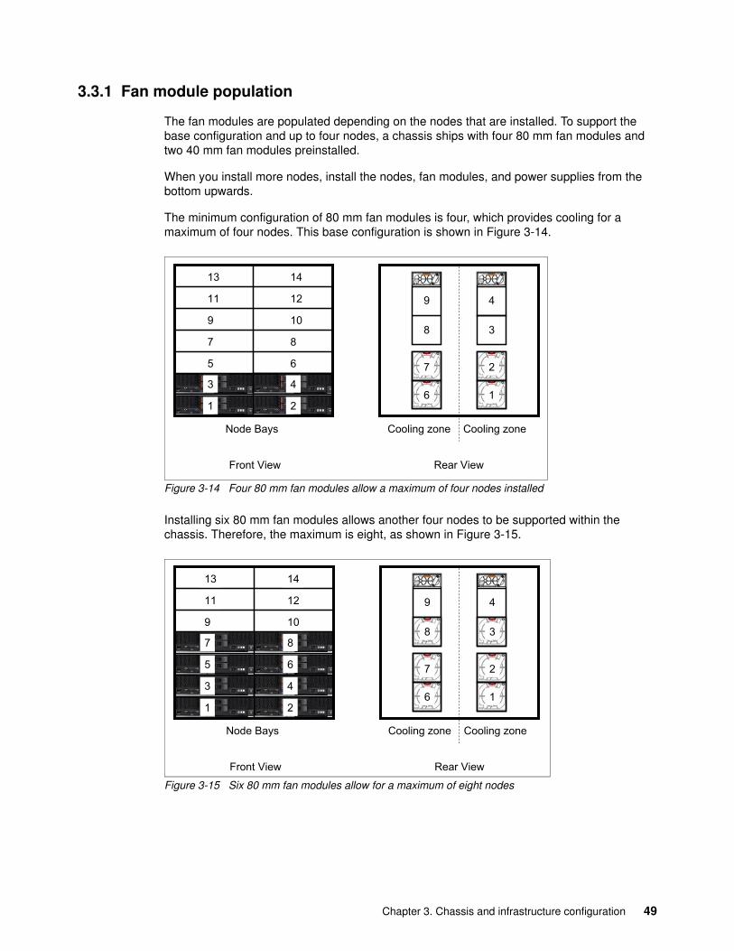
3.3.1 Fan module population
The fan modules are populated depending on the nodes that are installed. To support the base configuration and up to four nodes, a chassis ships with four 80 mm fan modules and two 40 mm fan modules preinstalled.
When you install more nodes, install the nodes, fan modules, and power supplies from the bottom upwards.
The minimum configuration of 80 mm fan modules is four, which provides cooling for a maximum of four nodes. This base configuration is shown in Figure 3-14.
Figure 3-14 Four 80 mm fan modules allow a maximum of four nodes installed
Installing six 80 mm fan modules allows another four nodes to be supported within the chassis. Therefore, the maximum is eight, as shown in Figure 3-15.
Figure 3-15 Six 80 mm fan modules allow for a maximum of eight nodes
Front View Rear View
Cooling zone Cooling zone
1 2
3 4
Node Bays
1
5
11
7
13
9
2
10
3 4
6
14
12
8
1
2
3
4
6
7
8
9
Rear View
Cooling zone Cooling zone
1
5
7
2
3 4
6
8
Node Bays
Front View
1
5
11
7
13
9
2
10
3 4
6
14
12
8
1
2
3
4
6
7
8
9
Chapter 3. Chassis and infrastructure configuration 49
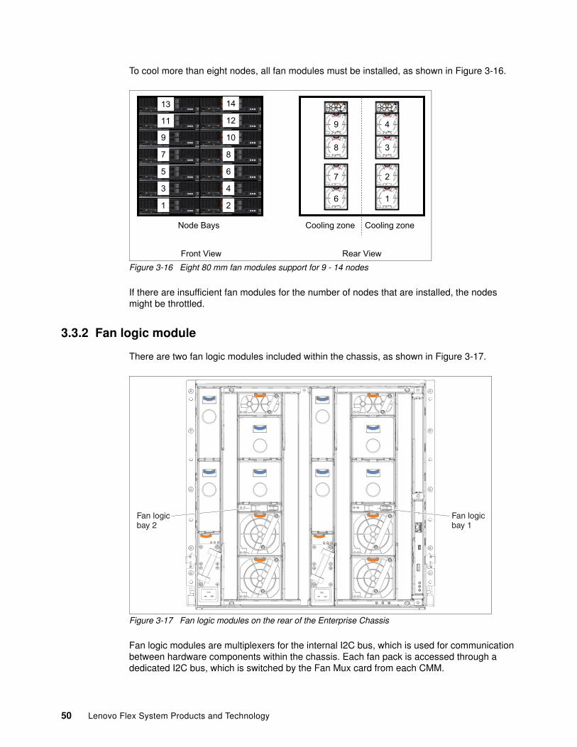
To cool more than eight nodes, all fan modules must be installed, as shown in Figure 3-16.
Figure 3-16 Eight 80 mm fan modules support for 9 - 14 nodes
If there are insufficient fan modules for the number of nodes that are installed, the nodes might be throttled.
3.3.2 Fan logic module
There are two fan logic modules included within the chassis, as shown in Figure 3-17.
Figure 3-17 Fan logic modules on the rear of the Enterprise Chassis
Fan logic modules are multiplexers for the internal I2C bus, which is used for communication between hardware components within the chassis. Each fan pack is accessed through a dedicated I2C bus, which is switched by the Fan Mux card from each CMM.
Rear View
Cooling zone Cooling zoneNode Bays
Front View
11
55
1111
77
1313
99
22
1010
33 44
66
1414
1212
88
1
2
3
4
6
7
8
9
Fan logicbay 2
Fan logicbay 1
50 Lenovo Flex System Products and Technology
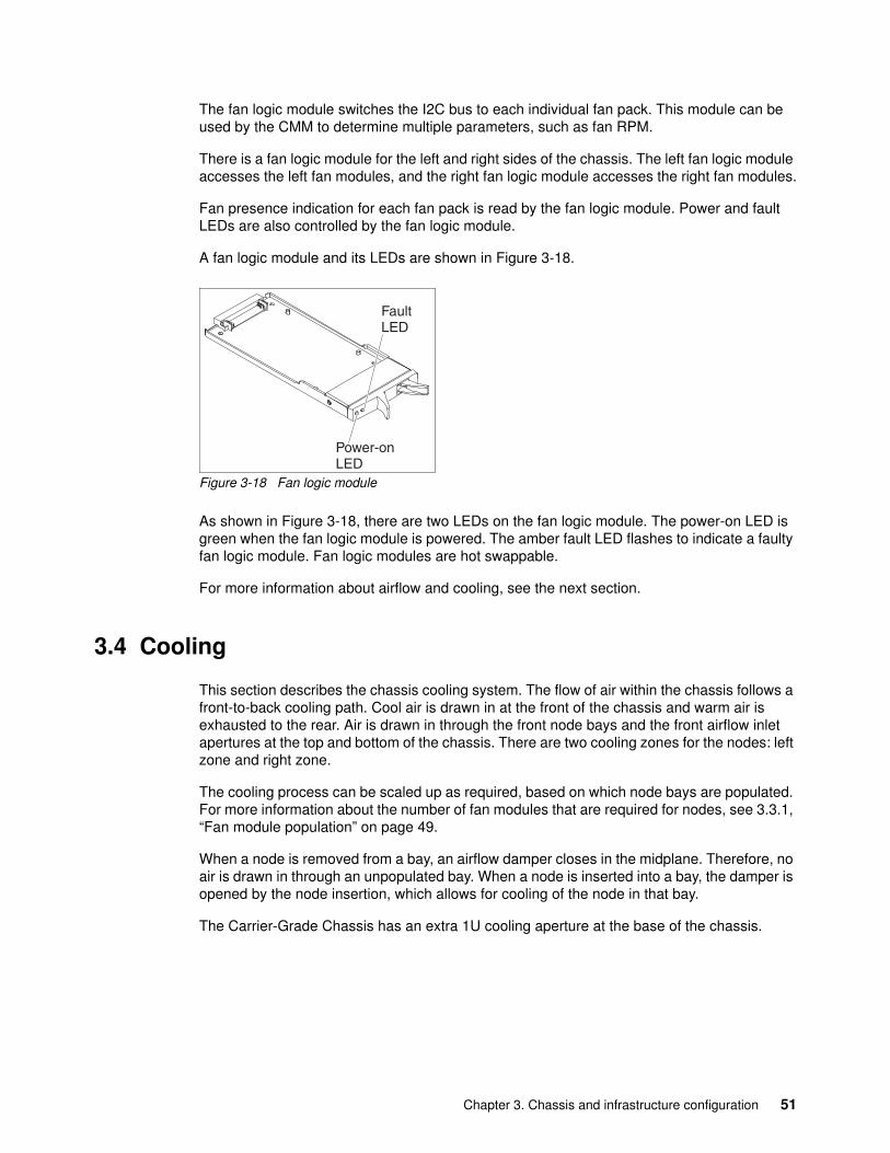
The fan logic module switches the I2C bus to each individual fan pack. This module can be used by the CMM to determine multiple parameters, such as fan RPM.
There is a fan logic module for the left and right sides of the chassis. The left fan logic module accesses the left fan modules, and the right fan logic module accesses the right fan modules.
Fan presence indication for each fan pack is read by the fan logic module. Power and fault LEDs are also controlled by the fan logic module.
A fan logic module and its LEDs are shown in Figure 3-18.
Figure 3-18 Fan logic module
As shown in Figure 3-18, there are two LEDs on the fan logic module. The power-on LED is green when the fan logic module is powered. The amber fault LED flashes to indicate a faulty fan logic module. Fan logic modules are hot swappable.
For more information about airflow and cooling, see the next section.
3.4 Cooling
This section describes the chassis cooling system. The flow of air within the chassis follows a front-to-back cooling path. Cool air is drawn in at the front of the chassis and warm air is exhausted to the rear. Air is drawn in through the front node bays and the front airflow inlet apertures at the top and bottom of the chassis. There are two cooling zones for the nodes: left zone and right zone.
The cooling process can be scaled up as required, based on which node bays are populated. For more information about the number of fan modules that are required for nodes, see 3.3.1, “Fan module population” on page 49.
When a node is removed from a bay, an airflow damper closes in the midplane. Therefore, no air is drawn in through an unpopulated bay. When a node is inserted into a bay, the damper is opened by the node insertion, which allows for cooling of the node in that bay.
The Carrier-Grade Chassis has an extra 1U cooling aperture at the base of the chassis.
Chapter 3. Chassis and infrastructure configuration 51
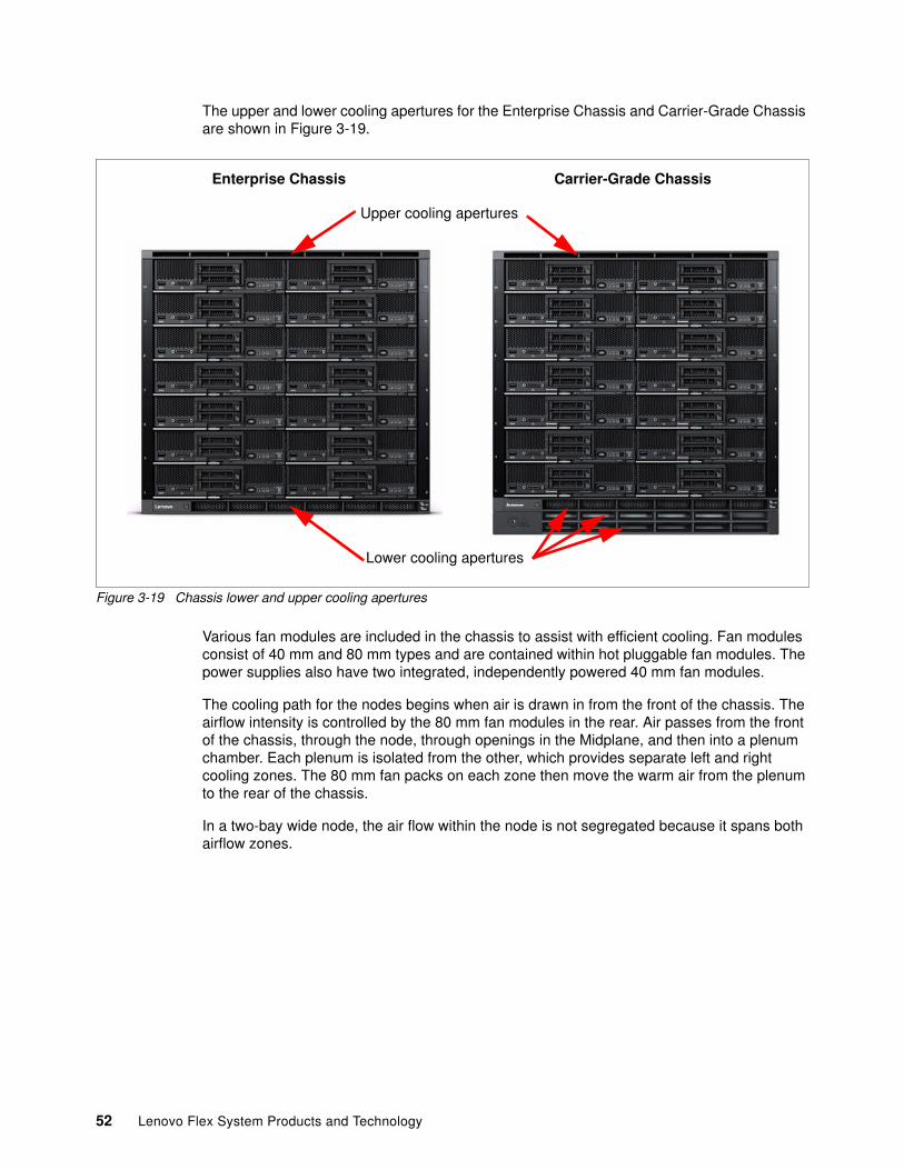
The upper and lower cooling apertures for the Enterprise Chassis and Carrier-Grade Chassis are shown in Figure 3-19.
Figure 3-19 Chassis lower and upper cooling apertures
Various fan modules are included in the chassis to assist with efficient cooling. Fan modules consist of 40 mm and 80 mm types and are contained within hot pluggable fan modules. The power supplies also have two integrated, independently powered 40 mm fan modules.
The cooling path for the nodes begins when air is drawn in from the front of the chassis. The airflow intensity is controlled by the 80 mm fan modules in the rear. Air passes from the front of the chassis, through the node, through openings in the Midplane, and then into a plenum chamber. Each plenum is isolated from the other, which provides separate left and right cooling zones. The 80 mm fan packs on each zone then move the warm air from the plenum to the rear of the chassis.
In a two-bay wide node, the air flow within the node is not segregated because it spans both airflow zones.
Upper cooling apertures
Lower cooling apertures
Enterprise Chassis Carrier-Grade Chassis
52 Lenovo Flex System Products and Technology
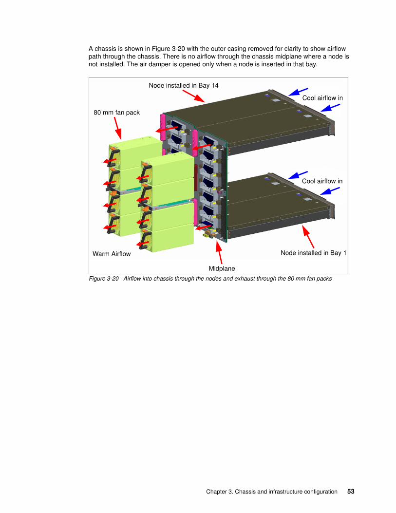
A chassis is shown in Figure 3-20 with the outer casing removed for clarity to show airflow path through the chassis. There is no airflow through the chassis midplane where a node is not installed. The air damper is opened only when a node is inserted in that bay.
Figure 3-20 Airflow into chassis through the nodes and exhaust through the 80 mm fan packs
Node installed in Bay 1
80 mm fan pack
Node installed in Bay 14
Cool airflow in
Warm Airflow
Midplane
Cool airflow in
Chapter 3. Chassis and infrastructure configuration 53
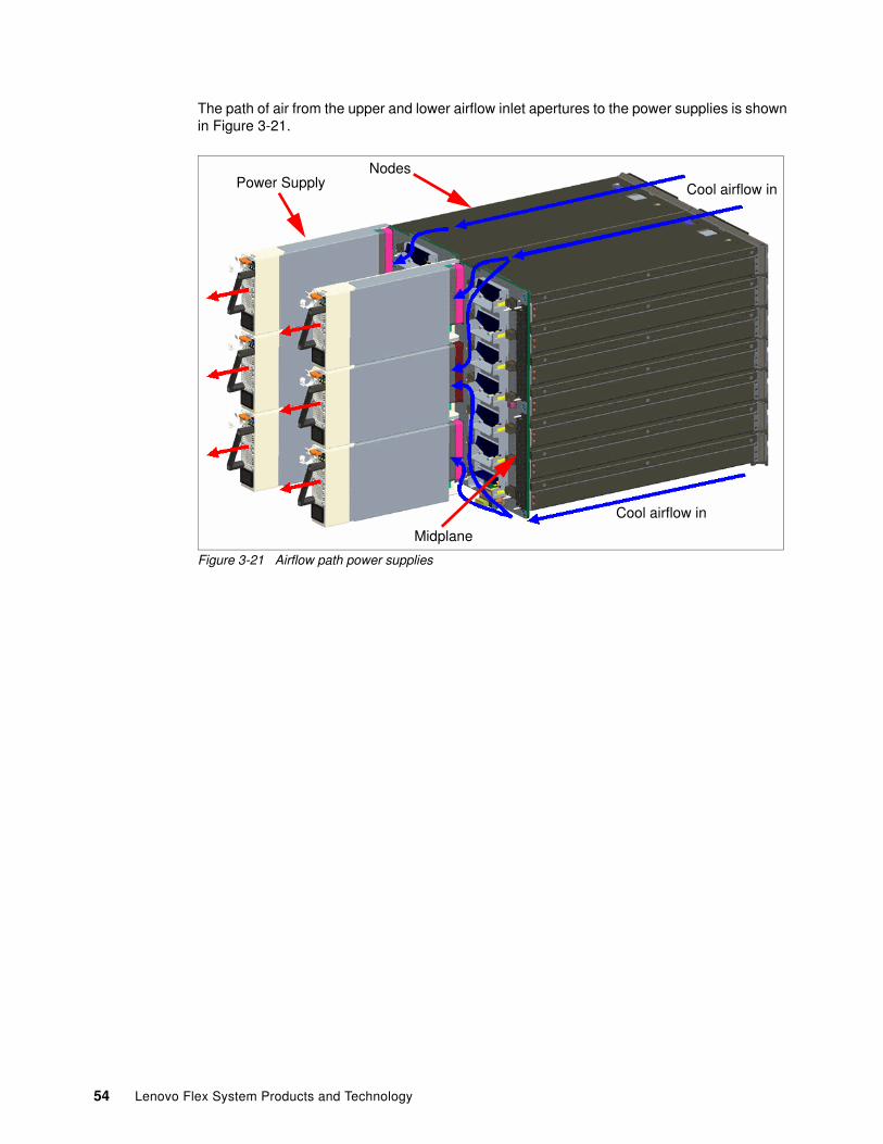
The path of air from the upper and lower airflow inlet apertures to the power supplies is shown in Figure 3-21.
Figure 3-21 Airflow path power supplies
Power Supply Cool airflow in
Nodes
Midplane
Cool airflow in
54 Lenovo Flex System Products and Technology
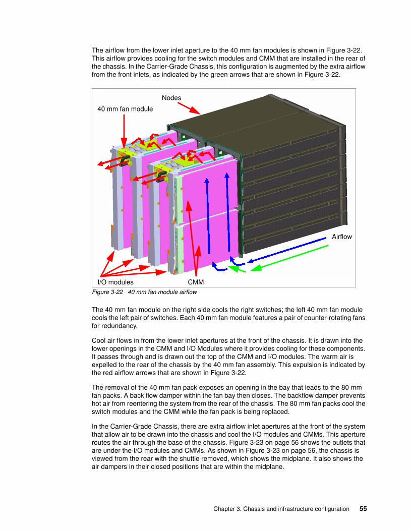
The airflow from the lower inlet aperture to the 40 mm fan modules is shown in Figure 3-22. This airflow provides cooling for the switch modules and CMM that are installed in the rear of the chassis. In the Carrier-Grade Chassis, this configuration is augmented by the extra airflow from the front inlets, as indicated by the green arrows that are shown in Figure 3-22.
Figure 3-22 40 mm fan module airflow
The 40 mm fan module on the right side cools the right switches; the left 40 mm fan module cools the left pair of switches. Each 40 mm fan module features a pair of counter-rotating fans for redundancy.
Cool air flows in from the lower inlet apertures at the front of the chassis. It is drawn into the lower openings in the CMM and I/O Modules where it provides cooling for these components. It passes through and is drawn out the top of the CMM and I/O modules. The warm air is expelled to the rear of the chassis by the 40 mm fan assembly. This expulsion is indicated by the red airflow arrows that are shown in Figure 3-22.
The removal of the 40 mm fan pack exposes an opening in the bay that leads to the 80 mm fan packs. A back flow damper within the fan bay then closes. The backflow damper prevents hot air from reentering the system from the rear of the chassis. The 80 mm fan packs cool the switch modules and the CMM while the fan pack is being replaced.
In the Carrier-Grade Chassis, there are extra airflow inlet apertures at the front of the system that allow air to be drawn into the chassis and cool the I/O modules and CMMs. This aperture routes the air through the base of the chassis. Figure 3-23 on page 56 shows the outlets that are under the I/O modules and CMMs. As shown in Figure 3-23 on page 56, the chassis is viewed from the rear with the shuttle removed, which shows the midplane. It also shows the air dampers in their closed positions that are within the midplane.
Nodes
Airflow
I/O modules
40 mm fan module
CMM
Chapter 3. Chassis and infrastructure configuration 55
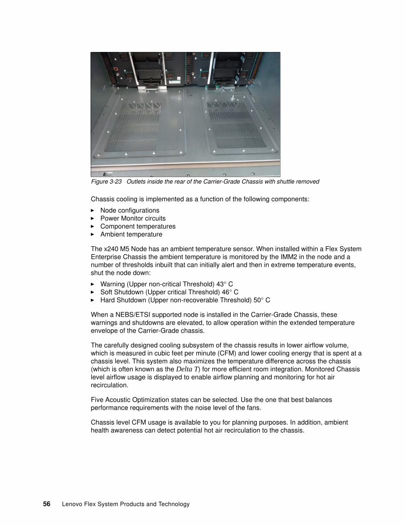
Figure 3-23 Outlets inside the rear of the Carrier-Grade Chassis with shuttle removed
Chassis cooling is implemented as a function of the following components:
� Node configurations� Power Monitor circuits� Component temperatures� Ambient temperature
The x240 M5 Node has an ambient temperature sensor. When installed within a Flex System Enterprise Chassis the ambient temperature is monitored by the IMM2 in the node and a number of thresholds inbuilt that can initially alert and then in extreme temperature events, shut the node down:
� Warning (Upper non-critical Threshold) 43° C� Soft Shutdown (Upper critical Threshold) 46° C� Hard Shutdown (Upper non-recoverable Threshold) 50° C
When a NEBS/ETSI supported node is installed in the Carrier-Grade Chassis, these warnings and shutdowns are elevated, to allow operation within the extended temperature envelope of the Carrier-Grade chassis.
The carefully designed cooling subsystem of the chassis results in lower airflow volume, which is measured in cubic feet per minute (CFM) and lower cooling energy that is spent at a chassis level. This system also maximizes the temperature difference across the chassis (which is often known as the Delta T) for more efficient room integration. Monitored Chassis level airflow usage is displayed to enable airflow planning and monitoring for hot air recirculation.
Five Acoustic Optimization states can be selected. Use the one that best balances performance requirements with the noise level of the fans.
Chassis level CFM usage is available to you for planning purposes. In addition, ambient health awareness can detect potential hot air recirculation to the chassis.
56 Lenovo Flex System Products and Technology
3.5 Power supplies
Power supplies (or power modules) are available with 2500 W rating. Power supplies are hot pluggable and are installed into the rear of the chassis. The following power supply options are available:
� 2500 W AC� 2500 W -48 V DC
The standard chassis models ship either with two or six 2500 W modules, or with two 2500 W -48 V DC power supplies, depending on the model chosen. The Carrier-Grade chassis ships with two 2500 W -48 V DC power supplies.
For more information about populating the 2500 W power supplies, see 3.5.1, “Power supply selection” on page 60, which also provides planning information for the nodes that are being installed.
A maximum of six power supplies can be installed within the Enterprise Chassis.
The 2500 W AC supplies are 2500 watts output rated at 200 - 208 VAC (nominal), and 2750 W at 220 - 240 V AC (nominal). The power supply has an oversubscription rating of up to 3538 W output at 200 V AC. The power supply operating range is 200 - 240 VAC.
The power supplies also contain two dual independently powered 40 mm cooling fans that are not powered by the power supply that is installed inside. Instead, they draw power from the chassis midplane. The fans are variable speed and controlled by the chassis fan logic.
The 2500 W -48 V DC power supply operates over a typical telecommunications range of -60 V to -48 V DC.
DC power systems in data centers1 include the following advantages:
� 10% better energy efficiency (not including the reduced need for cooling in the IT room)
� 15% lower investment costs
� 25% less space required
� 20% lower installation costs
� Computer equipment can connect directly to back up batteries
� DC powered data centers require fewer conversions for incoming electricity and require 25 - 40% less square footage than their AC counterparts2
Support of power supplies: Mixing of different power supply types is not supported in the same chassis.
1 For more information, see this website: http://www.mena.abb.com/cawp/chabb122/487aa5156d33f637c1257a0c0035cad6.aspx
2 For more information, see this website: https://www.greentechmedia.com/articles/read/a-hidden-benefit-of-dc-power-real-estate/
Chapter 3. Chassis and infrastructure configuration 57
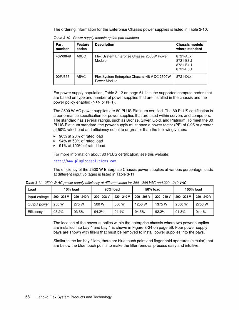
The ordering information for the Enterprise Chassis power supplies is listed in Table 3-10.
Table 3-10 Power supply module option part numbers
For power supply population, Table 3-12 on page 61 lists the supported compute nodes that are based on type and number of power supplies that are installed in the chassis and the power policy enabled (N+N or N+1).
The 2500 W AC power supplies are 80 PLUS Platinum certified. The 80 PLUS certification is a performance specification for power supplies that are used within servers and computers. The standard has several ratings, such as Bronze, Silver, Gold, and Platinum. To meet the 80 PLUS Platinum standard, the power supply must have a power factor (PF) of 0.95 or greater at 50% rated load and efficiency equal to or greater than the following values:
� 90% at 20% of rated load� 94% at 50% of rated load � 91% at 100% of rated load
For more information about 80 PLUS certification, see this website:
http://www.plugloadsolutions.com
The efficiency of the 2500 W Enterprise Chassis power supplies at various percentage loads at different input voltages is listed in Table 3-11.
Table 3-11 2500 W AC power supply efficiency at different loads for 200 - 208 VAC and 220 - 240 VAC
The location of the power supplies within the enterprise chassis where two power supplies are installed into bay 4 and bay 1 is shown in Figure 3-24 on page 59. Four power supply bays are shown with fillers that must be removed to install power supplies into the bays.
Similar to the fan bay fillers, there are blue touch point and finger hold apertures (circular) that are below the blue touch points to make the filler removal process easy and intuitive.
Partnumber
Featurecodes
Description Chassis modelswhere standard
43W9049 A0UC Flex System Enterprise Chassis 2500W Power Module
8721-ALx8721-E3U8721-E4U8721-E5U
00FJ635 A5VC Flex System Enterprise Chassis -48 V DC 2500W Power Module
8721-DLx
Load 10% load 20% load 50% load 100% load
Input voltage 200 - 208 V 220 - 240 V 200 - 208 V 220 - 240 V 200 - 208 V 220 - 240 V 200 - 208 V 220 - 240 V
Output power 250 W 275 W 500 W 550 W 1250 W 1375 W 2500 W 2750 W
Efficiency 93.2% 93.5% 94.2% 94.4% 94.5% 92.2% 91.8% 91.4%
58 Lenovo Flex System Products and Technology
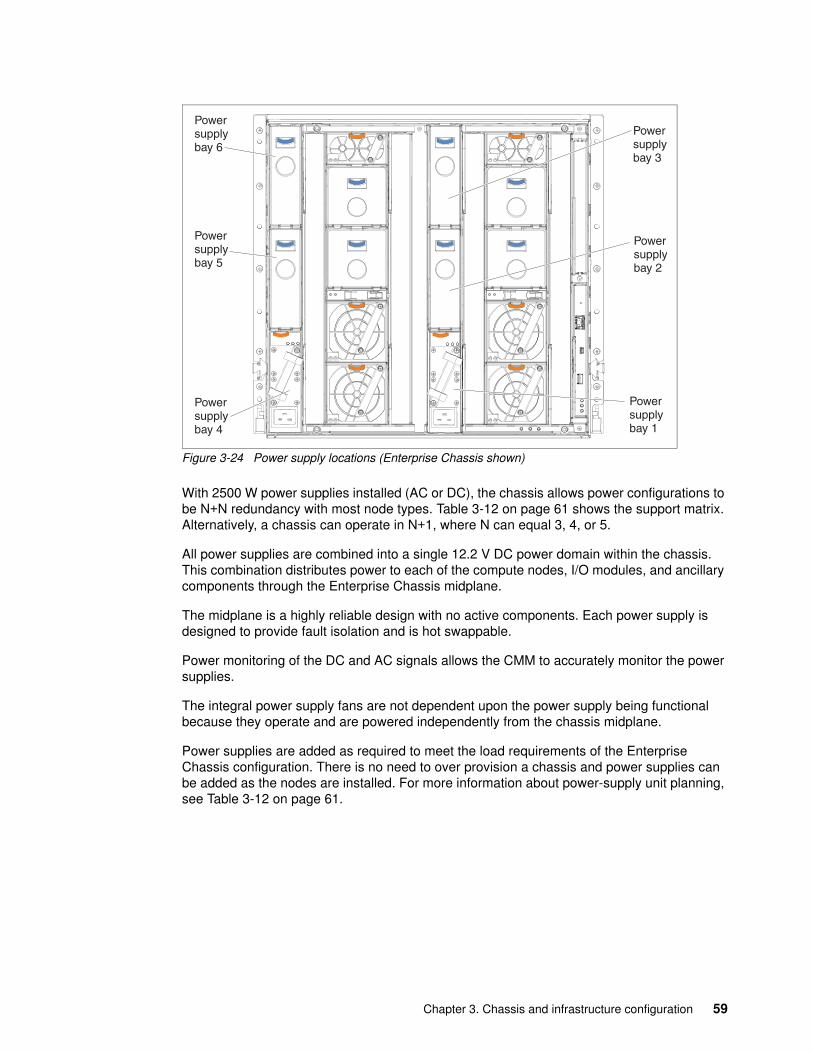
Figure 3-24 Power supply locations (Enterprise Chassis shown)
With 2500 W power supplies installed (AC or DC), the chassis allows power configurations to be N+N redundancy with most node types. Table 3-12 on page 61 shows the support matrix. Alternatively, a chassis can operate in N+1, where N can equal 3, 4, or 5.
All power supplies are combined into a single 12.2 V DC power domain within the chassis. This combination distributes power to each of the compute nodes, I/O modules, and ancillary components through the Enterprise Chassis midplane.
The midplane is a highly reliable design with no active components. Each power supply is designed to provide fault isolation and is hot swappable.
Power monitoring of the DC and AC signals allows the CMM to accurately monitor the power supplies.
The integral power supply fans are not dependent upon the power supply being functional because they operate and are powered independently from the chassis midplane.
Power supplies are added as required to meet the load requirements of the Enterprise Chassis configuration. There is no need to over provision a chassis and power supplies can be added as the nodes are installed. For more information about power-supply unit planning, see Table 3-12 on page 61.
Powersupplybay 6
Powersupplybay 5
Powersupplybay 4
Powersupplybay 1
Powersupplybay 3
Powersupplybay 2
Chapter 3. Chassis and infrastructure configuration 59
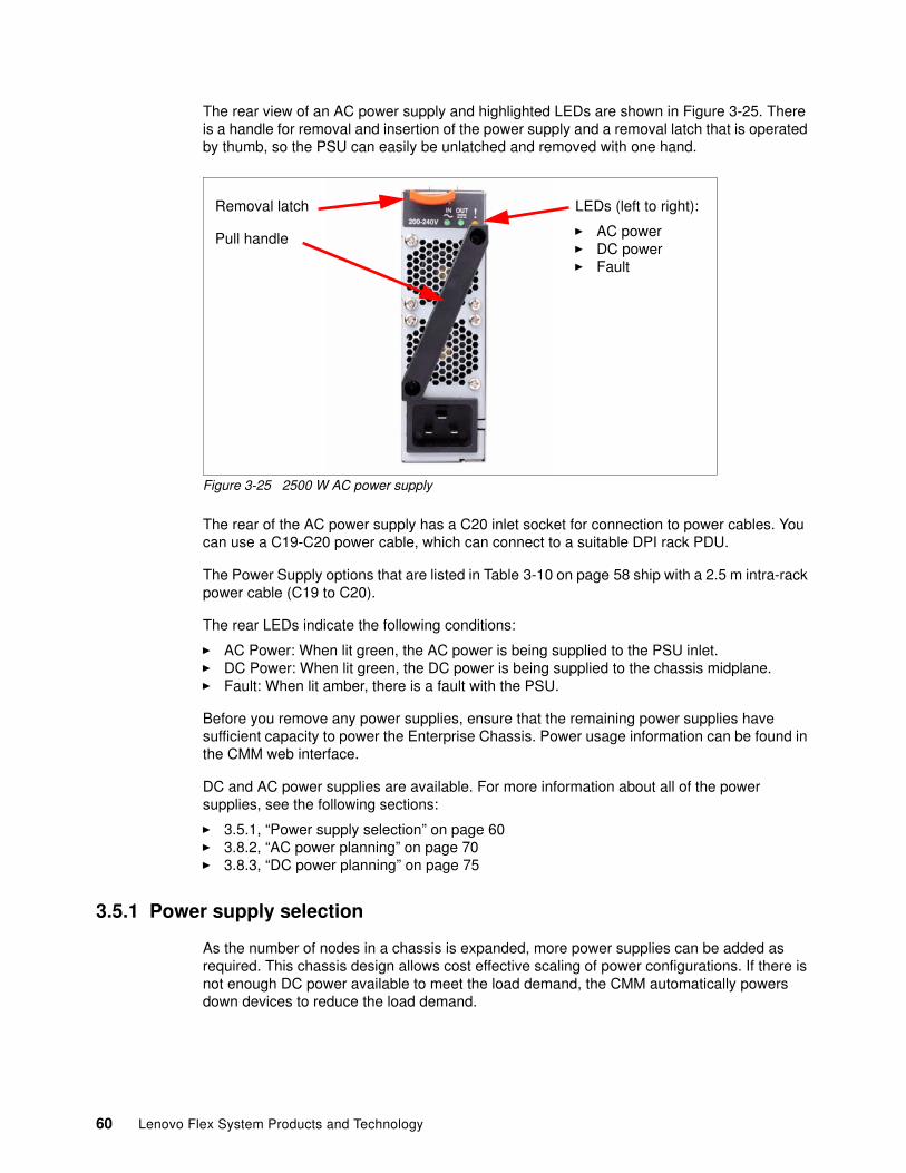
The rear view of an AC power supply and highlighted LEDs are shown in Figure 3-25. There is a handle for removal and insertion of the power supply and a removal latch that is operated by thumb, so the PSU can easily be unlatched and removed with one hand.
Figure 3-25 2500 W AC power supply
The rear of the AC power supply has a C20 inlet socket for connection to power cables. You can use a C19-C20 power cable, which can connect to a suitable DPI rack PDU.
The Power Supply options that are listed in Table 3-10 on page 58 ship with a 2.5 m intra-rack power cable (C19 to C20).
The rear LEDs indicate the following conditions:
� AC Power: When lit green, the AC power is being supplied to the PSU inlet. � DC Power: When lit green, the DC power is being supplied to the chassis midplane.� Fault: When lit amber, there is a fault with the PSU.
Before you remove any power supplies, ensure that the remaining power supplies have sufficient capacity to power the Enterprise Chassis. Power usage information can be found in the CMM web interface.
DC and AC power supplies are available. For more information about all of the power supplies, see the following sections:
� 3.5.1, “Power supply selection” on page 60� 3.8.2, “AC power planning” on page 70� 3.8.3, “DC power planning” on page 75
3.5.1 Power supply selection
As the number of nodes in a chassis is expanded, more power supplies can be added as required. This chassis design allows cost effective scaling of power configurations. If there is not enough DC power available to meet the load demand, the CMM automatically powers down devices to reduce the load demand.
LEDs (left to right):
� AC power� DC power� Fault
Removal latch
Pull handle
60 Lenovo Flex System Products and Technology
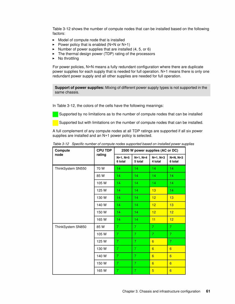
Table 3-12 shows the number of compute nodes that can be installed based on the following factors:
� Model of compute node that is installed� Power policy that is enabled (N+N or N+1)� Number of power supplies that are installed (4, 5, or 6)� The thermal design power (TDP) rating of the processors� No throttling
For power policies, N+N means a fully redundant configuration where there are duplicate power supplies for each supply that is needed for full operation. N+1 means there is only one redundant power supply and all other supplies are needed for full operation.
In Table 3-12, the colors of the cells have the following meanings:
Supported by no limitations as to the number of compute nodes that can be installed
Supported but with limitations on the number of compute nodes that can be installed.
A full complement of any compute nodes at all TDP ratings are supported if all six power supplies are installed and an N+1 power policy is selected.
Table 3-12 Specific number of compute nodes supported based on installed power supplies
Support of power supplies: Mixing of different power supply types is not supported in the same chassis.
Computenode
CPU TDPrating
2500 W power supplies (AC or DC)
N+1, N=56 total
N+1, N=45 total
N+1, N=34 total
N+N, N=36 total
ThinkSystem SN550 70 W 14 14 14 14
85 W 14 14 14 14
105 W 14 14 14 14
125 W 14 14 13 14
130 W 14 14 12 13
140 W 14 14 12 13
150 W 14 14 12 12
165 W 14 14 11 12
ThinkSystem SN850 85 W 7 7 7 7
105 W 7 7 7 7
125 W 7 7 6 7
130 W 7 7 6 6
140 W 7 7 6 6
150 W 7 7 6 6
165 W 7 7 5 6
Chapter 3. Chassis and infrastructure configuration 61
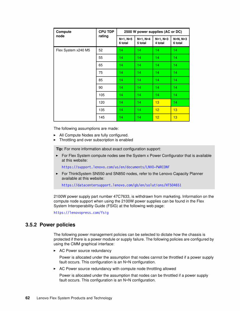
The following assumptions are made:
� All Compute Nodes are fully configured.� Throttling and over subscription is enabled
2100W power supply part number 47C7633, is withdrawn from marketing. Information on the compute node support when using the 2100W power supplies can be found in the Flex System Interoperability Guide (FSIG) at the following web page:
https://lenovopress.com/fsig
3.5.2 Power policies
The following power management policies can be selected to dictate how the chassis is protected if there is a power module or supply failure. The following policies are configured by using the CMM graphical interface:
� AC Power source redundancy
Power is allocated under the assumption that nodes cannot be throttled if a power supply fault occurs. This configuration is an N+N configuration.
� AC Power source redundancy with compute node throttling allowed
Power is allocated under the assumption that nodes can be throttled if a power supply fault occurs. This configuration is an N+N configuration.
Flex System x240 M5 52 14 14 14 14
55 14 14 14 14
65 14 14 14 14
75 14 14 14 14
85 14 14 14 14
90 14 14 14 14
105 14 14 14 14
120 14 14 13 14
135 14 14 12 13
145 14 14 12 13
Tip: For more information about exact configuration support:
� For Flex System compute nodes see the System x Power Configurator that is available at this website:
https://support.lenovo.com/us/en/documents/LNVO-PWRCONF
� For ThinkSystem SN550 and SN850 nodes, refer to the Lenovo Capacity Planner available at this website:
https://datacentersupport.lenovo.com/gb/en/solutions/HT504651
Computenode
CPU TDPrating
2500 W power supplies (AC or DC)
N+1, N=56 total
N+1, N=45 total
N+1, N=34 total
N+N, N=36 total
62 Lenovo Flex System Products and Technology
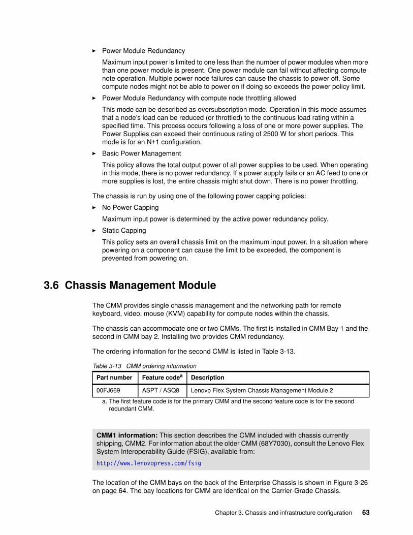
� Power Module Redundancy
Maximum input power is limited to one less than the number of power modules when more than one power module is present. One power module can fail without affecting compute note operation. Multiple power node failures can cause the chassis to power off. Some compute nodes might not be able to power on if doing so exceeds the power policy limit.
� Power Module Redundancy with compute node throttling allowed
This mode can be described as oversubscription mode. Operation in this mode assumes that a node’s load can be reduced (or throttled) to the continuous load rating within a specified time. This process occurs following a loss of one or more power supplies. The Power Supplies can exceed their continuous rating of 2500 W for short periods. This mode is for an N+1 configuration.
� Basic Power Management
This policy allows the total output power of all power supplies to be used. When operating in this mode, there is no power redundancy. If a power supply fails or an AC feed to one or more supplies is lost, the entire chassis might shut down. There is no power throttling.
The chassis is run by using one of the following power capping policies:
� No Power Capping
Maximum input power is determined by the active power redundancy policy.
� Static Capping
This policy sets an overall chassis limit on the maximum input power. In a situation where powering on a component can cause the limit to be exceeded, the component is prevented from powering on.
3.6 Chassis Management Module
The CMM provides single chassis management and the networking path for remote keyboard, video, mouse (KVM) capability for compute nodes within the chassis.
The chassis can accommodate one or two CMMs. The first is installed in CMM Bay 1 and the second in CMM bay 2. Installing two provides CMM redundancy.
The ordering information for the second CMM is listed in Table 3-13.
Table 3-13 CMM ordering information
The location of the CMM bays on the back of the Enterprise Chassis is shown in Figure 3-26 on page 64. The bay locations for CMM are identical on the Carrier-Grade Chassis.
Part number Feature codea
a. The first feature code is for the primary CMM and the second feature code is for the second redundant CMM.
Description
00FJ669 ASPT / ASQ8 Lenovo Flex System Chassis Management Module 2
CMM1 information: This section describes the CMM included with chassis currently shipping, CMM2. For information about the older CMM (68Y7030), consult the Lenovo Flex System Interoperability Guide (FSIG), available from:
http://www.lenovopress.com/fsig
Chapter 3. Chassis and infrastructure configuration 63
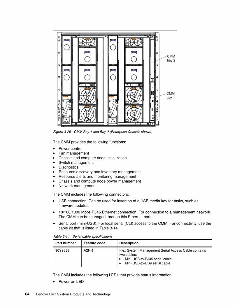
Figure 3-26 CMM Bay 1 and Bay 2 (Enterprise Chassis shown)
The CMM provides the following functions:
� Power control� Fan management� Chassis and compute node initialization� Switch management� Diagnostics� Resource discovery and inventory management� Resource alerts and monitoring management� Chassis and compute node power management� Network management
The CMM includes the following connectors:
� USB connection: Can be used for insertion of a USB media key for tasks, such as firmware updates.
� 10/100/1000 Mbps RJ45 Ethernet connection: For connection to a management network. The CMM can be managed through this Ethernet port.
� Serial port (mini-USB): For local serial (CLI) access to the CMM. For connectivity, use the cable kit that is listed in Table 3-14.
Table 3-14 Serial cable specifications
The CMM includes the following LEDs that provide status information:
� Power-on LED
Part number Feature code Description
90Y9338 A2RR Flex System Management Serial Access Cable contains two cables:� Mini-USB-to-RJ45 serial cable � Mini-USB-to-DB9 serial cable
64 Lenovo Flex System Products and Technology
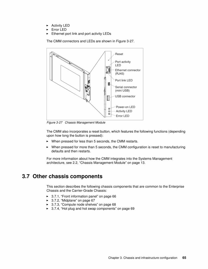
� Activity LED� Error LED� Ethernet port link and port activity LEDs
The CMM connectors and LEDs are shown in Figure 3-27.
Figure 3-27 Chassis Management Module
The CMM also incorporates a reset button, which features the following functions (depending upon how long the button is pressed):
� When pressed for less than 5 seconds, the CMM restarts.
� When pressed for more than 5 seconds, the CMM configuration is reset to manufacturing defaults and then restarts.
For more information about how the CMM integrates into the Systems Management architecture, see 2.2, “Chassis Management Module” on page 13.
3.7 Other chassis components
This section describes the following chassis components that are common to the Enterprise Chassis and the Carrier-Grade Chassis:
� 3.7.1, “Front information panel” on page 66� 3.7.2, “Midplane” on page 67� 3.7.3, “Compute node shelves” on page 68� 3.7.4, “Hot plug and hot swap components” on page 69
Chapter 3. Chassis and infrastructure configuration 65
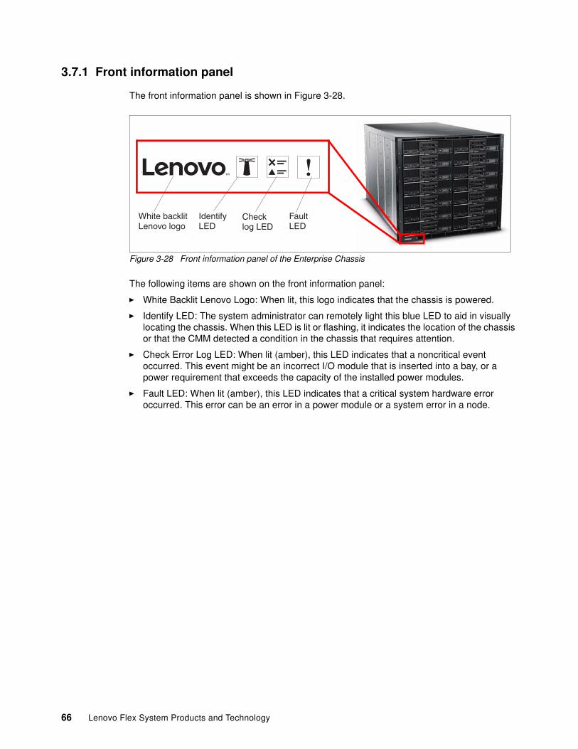
3.7.1 Front information panel
The front information panel is shown in Figure 3-28.
Figure 3-28 Front information panel of the Enterprise Chassis
The following items are shown on the front information panel:
� White Backlit Lenovo Logo: When lit, this logo indicates that the chassis is powered.
� Identify LED: The system administrator can remotely light this blue LED to aid in visually locating the chassis. When this LED is lit or flashing, it indicates the location of the chassis or that the CMM detected a condition in the chassis that requires attention.
� Check Error Log LED: When lit (amber), this LED indicates that a noncritical event occurred. This event might be an incorrect I/O module that is inserted into a bay, or a power requirement that exceeds the capacity of the installed power modules.
� Fault LED: When lit (amber), this LED indicates that a critical system hardware error occurred. This error can be an error in a power module or a system error in a node.
!
White backlitLenovo logo
IdentifyLED
FaultLED
Checklog LED
66 Lenovo Flex System Products and Technology
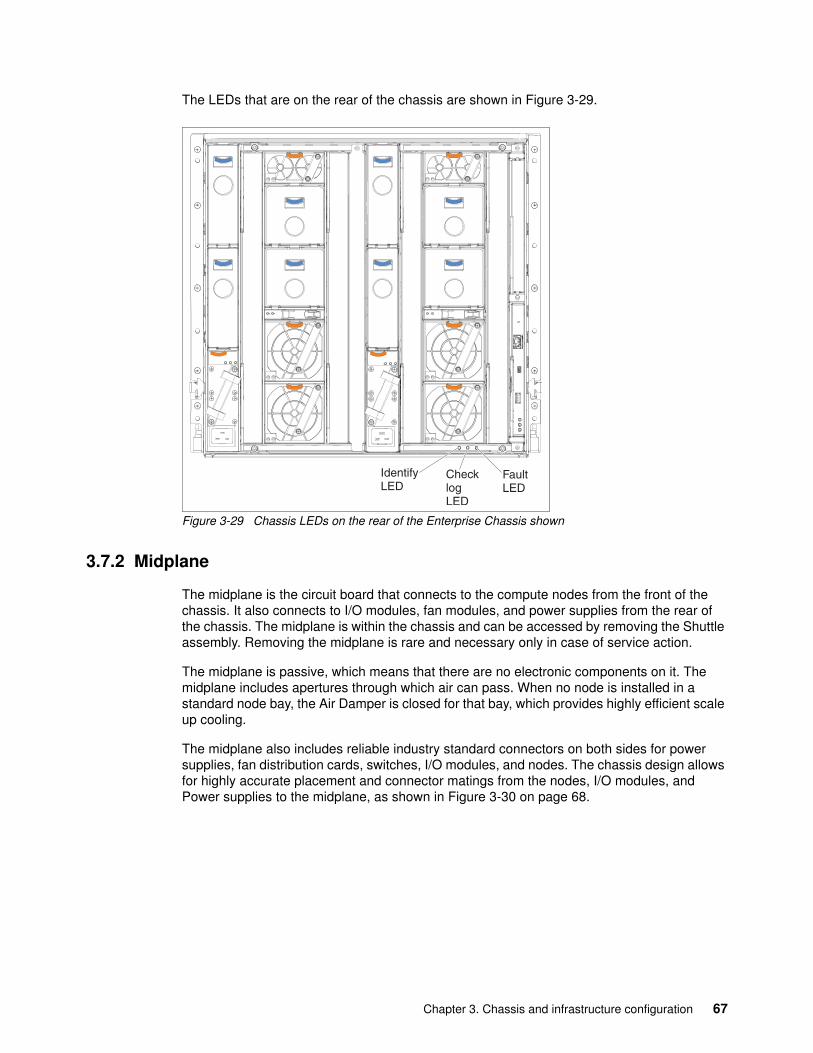
The LEDs that are on the rear of the chassis are shown in Figure 3-29.
Figure 3-29 Chassis LEDs on the rear of the Enterprise Chassis shown
3.7.2 Midplane
The midplane is the circuit board that connects to the compute nodes from the front of the chassis. It also connects to I/O modules, fan modules, and power supplies from the rear of the chassis. The midplane is within the chassis and can be accessed by removing the Shuttle assembly. Removing the midplane is rare and necessary only in case of service action.
The midplane is passive, which means that there are no electronic components on it. The midplane includes apertures through which air can pass. When no node is installed in a standard node bay, the Air Damper is closed for that bay, which provides highly efficient scale up cooling.
The midplane also includes reliable industry standard connectors on both sides for power supplies, fan distribution cards, switches, I/O modules, and nodes. The chassis design allows for highly accurate placement and connector matings from the nodes, I/O modules, and Power supplies to the midplane, as shown in Figure 3-30 on page 68.
IdentifyLED
ChecklogLED
FaultLED
Chapter 3. Chassis and infrastructure configuration 67
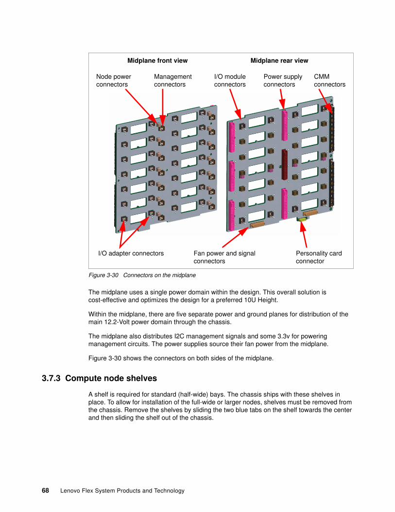
Figure 3-30 Connectors on the midplane
The midplane uses a single power domain within the design. This overall solution is cost-effective and optimizes the design for a preferred 10U Height.
Within the midplane, there are five separate power and ground planes for distribution of the main 12.2-Volt power domain through the chassis.
The midplane also distributes I2C management signals and some 3.3v for powering management circuits. The power supplies source their fan power from the midplane.
Figure 3-30 shows the connectors on both sides of the midplane.
3.7.3 Compute node shelves
A shelf is required for standard (half-wide) bays. The chassis ships with these shelves in place. To allow for installation of the full-wide or larger nodes, shelves must be removed from the chassis. Remove the shelves by sliding the two blue tabs on the shelf towards the center and then sliding the shelf out of the chassis.
I/O adapter connectors
Midplane front view Midplane rear view
Node power connectors
Management connectors
I/O module connectors
Power supply connectors
Fan power and signal connectors
CMM connectors
Personality card connector
68 Lenovo Flex System Products and Technology
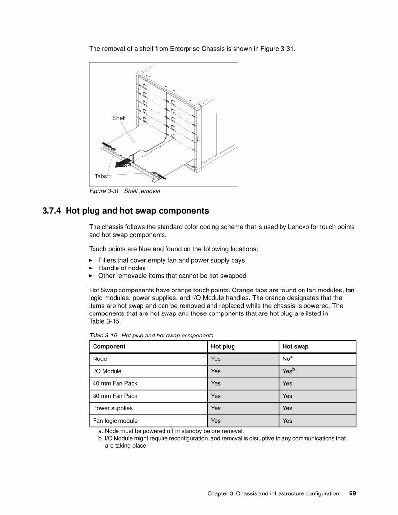
The removal of a shelf from Enterprise Chassis is shown in Figure 3-31.
Figure 3-31 Shelf removal
3.7.4 Hot plug and hot swap components
The chassis follows the standard color coding scheme that is used by Lenovo for touch points and hot swap components.
Touch points are blue and found on the following locations:
� Fillers that cover empty fan and power supply bays� Handle of nodes� Other removable items that cannot be hot-swapped
Hot Swap components have orange touch points. Orange tabs are found on fan modules, fan logic modules, power supplies, and I/O Module handles. The orange designates that the items are hot swap and can be removed and replaced while the chassis is powered. The components that are hot swap and those components that are hot plug are listed in Table 3-15.
Table 3-15 Hot plug and hot swap components
Tabs
Shelf
Component Hot plug Hot swap
Node Yes Noa
a. Node must be powered off in standby before removal.
I/O Module Yes Yesb
b. I/O Module might require reconfiguration, and removal is disruptive to any communications that are taking place.
40 mm Fan Pack Yes Yes
80 mm Fan Pack Yes Yes
Power supplies Yes Yes
Fan logic module Yes Yes
Chapter 3. Chassis and infrastructure configuration 69
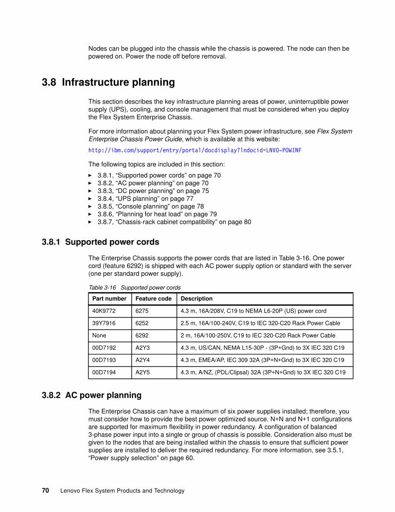
Nodes can be plugged into the chassis while the chassis is powered. The node can then be powered on. Power the node off before removal.
3.8 Infrastructure planning
This section describes the key infrastructure planning areas of power, uninterruptible power supply (UPS), cooling, and console management that must be considered when you deploy the Flex System Enterprise Chassis.
For more information about planning your Flex System power infrastructure, see Flex System Enterprise Chassis Power Guide, which is available at this website:
http://ibm.com/support/entry/portal/docdisplay?lndocid=LNVO-POWINF
The following topics are included in this section:
� 3.8.1, “Supported power cords” on page 70� 3.8.2, “AC power planning” on page 70� 3.8.3, “DC power planning” on page 75� 3.8.4, “UPS planning” on page 77� 3.8.5, “Console planning” on page 78� 3.8.6, “Planning for heat load” on page 79� 3.8.7, “Chassis-rack cabinet compatibility” on page 80
3.8.1 Supported power cords
The Enterprise Chassis supports the power cords that are listed in Table 3-16. One power cord (feature 6292) is shipped with each AC power supply option or standard with the server (one per standard power supply).
Table 3-16 Supported power cords
3.8.2 AC power planning
The Enterprise Chassis can have a maximum of six power supplies installed; therefore, you must consider how to provide the best power optimized source. N+N and N+1 configurations are supported for maximum flexibility in power redundancy. A configuration of balanced 3-phase power input into a single or group of chassis is possible. Consideration also must be given to the nodes that are being installed within the chassis to ensure that sufficient power supplies are installed to deliver the required redundancy. For more information, see 3.5.1, “Power supply selection” on page 60.
Part number Feature code Description
40K9772 6275 4.3 m, 16A/208V, C19 to NEMA L6-20P (US) power cord
39Y7916 6252 2.5 m, 16A/100-240V, C19 to IEC 320-C20 Rack Power Cable
None 6292 2 m, 16A/100-250V, C19 to IEC 320-C20 Rack Power Cable
00D7192 A2Y3 4.3 m, US/CAN, NEMA L15-30P - (3P+Gnd) to 3X IEC 320 C19
00D7193 A2Y4 4.3 m, EMEA/AP, IEC 309 32A (3P+N+Gnd) to 3X IEC 320 C19
00D7194 A2Y5 4.3 m, A/NZ, (PDL/Clipsal) 32A (3P+N+Gnd) to 3X IEC 320 C19
70 Lenovo Flex System Products and Technology

Each AC power supply in the chassis has a 16 A C20 3-pin socket and can be fed by a C19 power cable from a suitable supply. (The DC power supplies have different unique connectors, as described in 3.8.3, “DC power planning” on page 75).
The chassis power system is designed for efficiency by using data center power that consists of 3-phase, 60 A Delta 200 VAC (North America), or 3-phase 32 A wye 380-415 VAC (international). The chassis can also be fed from single phase 200 - 240 VAC supplies, if required.
The power is scaled as required; therefore, as more nodes are added, the power and cooling increases. For power planning, Table 3-12 on page 61 shows the number of power supplies that are needed for N+N or N+1, which is node type dependent.
This section describes single phase and 3-phase example configurations for North America and worldwide, starting with 3-phase. It is assumed that you have power budget in your configuration to deliver N+N or N+1 regarding your particular node configuration.
Chapter 3. Chassis and infrastructure configuration 71
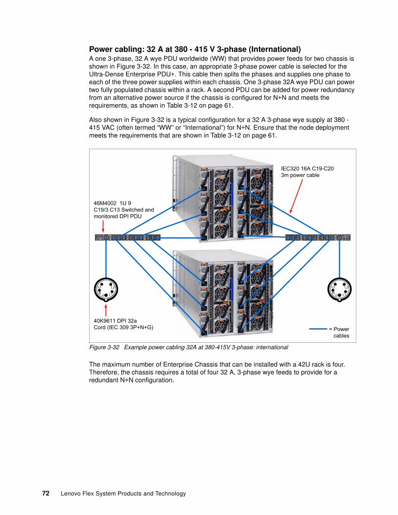
Power cabling: 32 A at 380 - 415 V 3-phase (International)A one 3-phase, 32 A wye PDU worldwide (WW) that provides power feeds for two chassis is shown in Figure 3-32. In this case, an appropriate 3-phase power cable is selected for the Ultra-Dense Enterprise PDU+. This cable then splits the phases and supplies one phase to each of the three power supplies within each chassis. One 3-phase 32A wye PDU can power two fully populated chassis within a rack. A second PDU can be added for power redundancy from an alternative power source if the chassis is configured for N+N and meets the requirements, as shown in Table 3-12 on page 61.
Also shown in Figure 3-32 is a typical configuration for a 32 A 3-phase wye supply at 380 - 415 VAC (often termed “WW” or “International”) for N+N. Ensure that the node deployment meets the requirements that are shown in Table 3-12 on page 61.
Figure 3-32 Example power cabling 32A at 380-415V 3-phase: international
The maximum number of Enterprise Chassis that can be installed with a 42U rack is four. Therefore, the chassis requires a total of four 32 A, 3-phase wye feeds to provide for a redundant N+N configuration.
����������� �����������������
������������������������������� !�
�"������#����$�����%�&'�(����)���)&'�����������#
*
*�*�
� *
*�*�
�
+�����������,
72 Lenovo Flex System Products and Technology
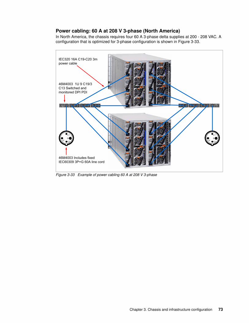
Power cabling: 60 A at 208 V 3-phase (North America)In North America, the chassis requires four 60 A 3-phase delta supplies at 200 - 208 VAC. A configuration that is optimized for 3-phase configuration is shown in Figure 3-33.
Figure 3-33 Example of power cabling 60 A at 208 V 3-phase
IEC320 16A C19-C20 3mpower cable
46M4003 Includes fixedIEC60309 3P+G 60A line cord
46M4003 1U 9 C19/3C13 Switched andmonitored DPI PDI
L1
L2 L3G
L1
L2 L3G
Chapter 3. Chassis and infrastructure configuration 73
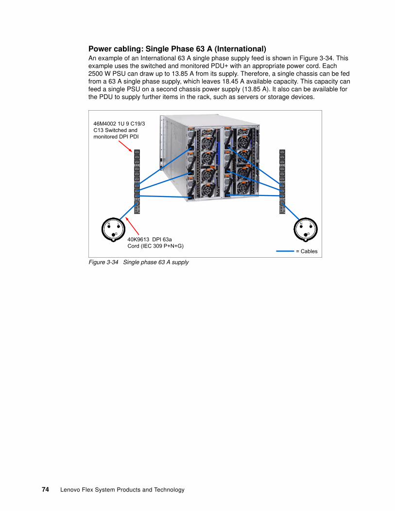
Power cabling: Single Phase 63 A (International)An example of an International 63 A single phase supply feed is shown in Figure 3-34. This example uses the switched and monitored PDU+ with an appropriate power cord. Each 2500 W PSU can draw up to 13.85 A from its supply. Therefore, a single chassis can be fed from a 63 A single phase supply, which leaves 18.45 A available capacity. This capacity can feed a single PSU on a second chassis power supply (13.85 A). It also can be available for the PDU to supply further items in the rack, such as servers or storage devices.
Figure 3-34 Single phase 63 A supply
�
*�
*
�������������������������������� !
�"�����#�����$����%�&'�(����)���)&'������������
+������,
74 Lenovo Flex System Products and Technology
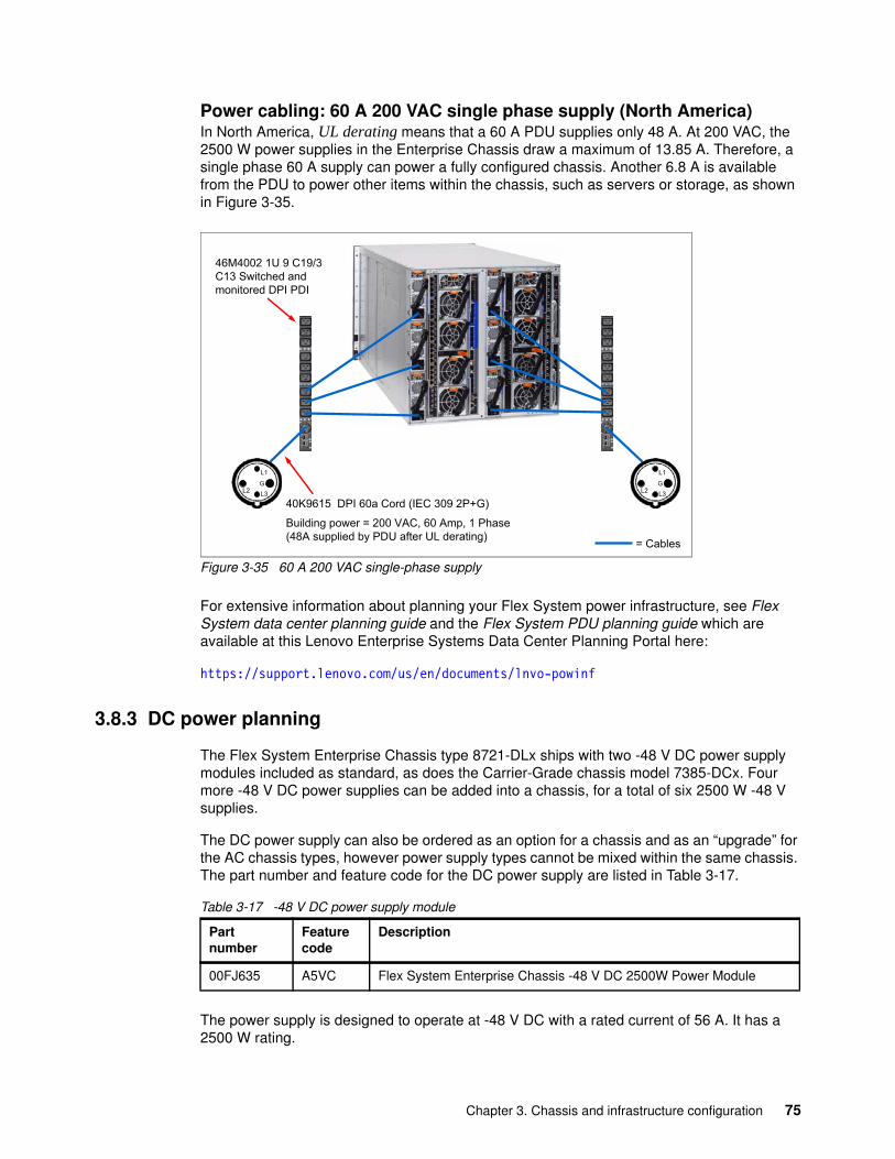
Power cabling: 60 A 200 VAC single phase supply (North America)In North America, UL derating means that a 60 A PDU supplies only 48 A. At 200 VAC, the 2500 W power supplies in the Enterprise Chassis draw a maximum of 13.85 A. Therefore, a single phase 60 A supply can power a fully configured chassis. Another 6.8 A is available from the PDU to power other items within the chassis, such as servers or storage, as shown in Figure 3-35.
Figure 3-35 60 A 200 VAC single-phase supply
For extensive information about planning your Flex System power infrastructure, see Flex System data center planning guide and the Flex System PDU planning guide which are available at this Lenovo Enterprise Systems Data Center Planning Portal here:
https://support.lenovo.com/us/en/documents/lnvo-powinf
3.8.3 DC power planning
The Flex System Enterprise Chassis type 8721-DLx ships with two -48 V DC power supply modules included as standard, as does the Carrier-Grade chassis model 7385-DCx. Four more -48 V DC power supplies can be added into a chassis, for a total of six 2500 W -48 V supplies.
The DC power supply can also be ordered as an option for a chassis and as an “upgrade” for the AC chassis types, however power supply types cannot be mixed within the same chassis. The part number and feature code for the DC power supply are listed in Table 3-17.
Table 3-17 -48 V DC power supply module
The power supply is designed to operate at -48 V DC with a rated current of 56 A. It has a 2500 W rating.
*
*� *�
*
*� *�
����5�������������������������� !
67&��&)/�������+�����8��9������9���(�,���4��,7���&����:���#��;'���#*�����'&)/!
�"�����#�����$����%�&'�(����)���)&'������������
+������,
Part number
Feature code
Description
00FJ635 A5VC Flex System Enterprise Chassis -48 V DC 2500W Power Module
Chapter 3. Chassis and infrastructure configuration 75
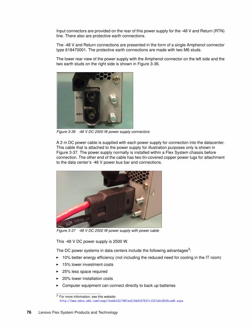
Input connectors are provided on the rear of this power supply for the -48 V and Return (RTN) line. There also are protective earth connections.
The -48 V and Return connections are presented in the form of a single Amphenol connector type 618470001. The protective earth connections are made with two M6 studs.
The lower rear view of the power supply with the Amphenol connector on the left side and the two earth studs on the right side is shown in Figure 3-36.
Figure 3-36 -48 V DC 2500 W power supply connectors
A 2 m DC power cable is supplied with each power supply for connection into the datacenter. This cable that is attached to the power supply for illustration purposes only is shown in Figure 3-37. The power supply normally is installed within a Flex System chassis before connection. The other end of the cable has two tin-covered copper power lugs for attachment to the data center’s -48 V power bus bar and connections.
Figure 3-37 -48 V DC 2500 W power supply with power cable
This -48 V DC power supply is 2500 W.
The DC power systems in data centers include the following advantages3:
� 10% better energy efficiency (not including the reduced need for cooling in the IT room)
� 15% lower investment costs
� 25% less space required
� 20% lower installation costs
� Computer equipment can connect directly to back up batteries
3 For more information, see this website:http://www.mena.abb.com/cawp/chabb122/487aa5156d33f637c1257a0c0035cad6.aspx
76 Lenovo Flex System Products and Technology
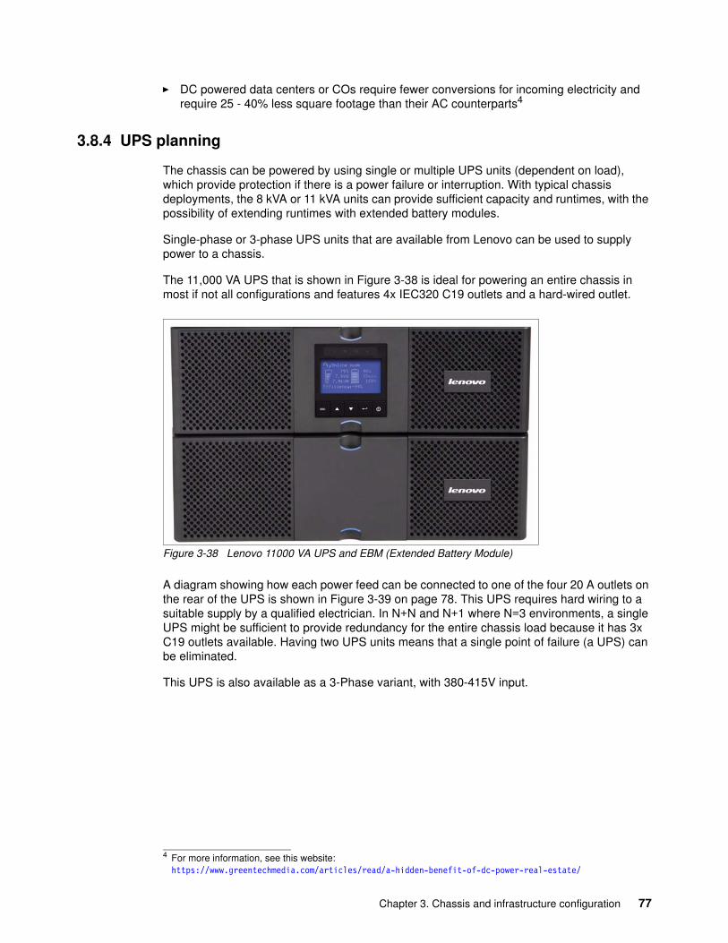
� DC powered data centers or COs require fewer conversions for incoming electricity and require 25 - 40% less square footage than their AC counterparts4
3.8.4 UPS planning
The chassis can be powered by using single or multiple UPS units (dependent on load), which provide protection if there is a power failure or interruption. With typical chassis deployments, the 8 kVA or 11 kVA units can provide sufficient capacity and runtimes, with the possibility of extending runtimes with extended battery modules.
Single-phase or 3-phase UPS units that are available from Lenovo can be used to supply power to a chassis.
The 11,000 VA UPS that is shown in Figure 3-38 is ideal for powering an entire chassis in most if not all configurations and features 4x IEC320 C19 outlets and a hard-wired outlet.
Figure 3-38 Lenovo 11000 VA UPS and EBM (Extended Battery Module)
A diagram showing how each power feed can be connected to one of the four 20 A outlets on the rear of the UPS is shown in Figure 3-39 on page 78. This UPS requires hard wiring to a suitable supply by a qualified electrician. In N+N and N+1 where N=3 environments, a single UPS might be sufficient to provide redundancy for the entire chassis load because it has 3x C19 outlets available. Having two UPS units means that a single point of failure (a UPS) can be eliminated.
This UPS is also available as a 3-Phase variant, with 380-415V input.
4 For more information, see this website: https://www.greentechmedia.com/articles/read/a-hidden-benefit-of-dc-power-real-estate/
Chapter 3. Chassis and infrastructure configuration 77
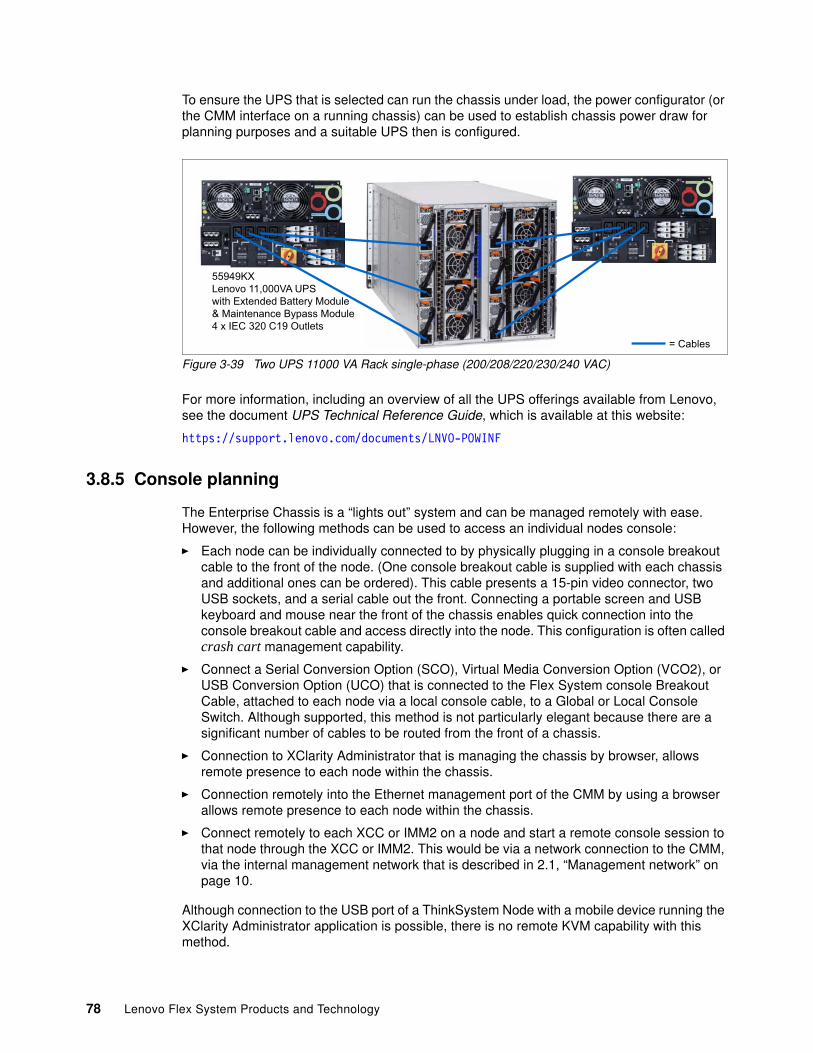
To ensure the UPS that is selected can run the chassis under load, the power configurator (or the CMM interface on a running chassis) can be used to establish chassis power draw for planning purposes and a suitable UPS then is configured.
Figure 3-39 Two UPS 11000 VA Rack single-phase (200/208/220/230/240 VAC)
For more information, including an overview of all the UPS offerings available from Lenovo, see the document UPS Technical Reference Guide, which is available at this website:
https://support.lenovo.com/documents/LNVO-POWINF
3.8.5 Console planning
The Enterprise Chassis is a “lights out” system and can be managed remotely with ease. However, the following methods can be used to access an individual nodes console:
� Each node can be individually connected to by physically plugging in a console breakout cable to the front of the node. (One console breakout cable is supplied with each chassis and additional ones can be ordered). This cable presents a 15-pin video connector, two USB sockets, and a serial cable out the front. Connecting a portable screen and USB keyboard and mouse near the front of the chassis enables quick connection into the console breakout cable and access directly into the node. This configuration is often called crash cart management capability.
� Connect a Serial Conversion Option (SCO), Virtual Media Conversion Option (VCO2), or USB Conversion Option (UCO) that is connected to the Flex System console Breakout Cable, attached to each node via a local console cable, to a Global or Local Console Switch. Although supported, this method is not particularly elegant because there are a significant number of cables to be routed from the front of a chassis.
� Connection to XClarity Administrator that is managing the chassis by browser, allows remote presence to each node within the chassis.
� Connection remotely into the Ethernet management port of the CMM by using a browser allows remote presence to each node within the chassis.
� Connect remotely to each XCC or IMM2 on a node and start a remote console session to that node through the XCC or IMM2. This would be via a network connection to the CMM, via the internal management network that is described in 2.1, “Management network” on page 10.
Although connection to the USB port of a ThinkSystem Node with a mobile device running the XClarity Administrator application is possible, there is no remote KVM capability with this method.
55949KXLenovo 11,000VA UPS with Extended Battery Module& Maintenance Bypass Module4 x IEC 320 C19 Outlets
= Cables
78 Lenovo Flex System Products and Technology
The ordering part number and feature code are listed in Table 3-18.
Table 3-18 Ordering part number and feature code
3.8.6 Planning for heat load
The Enterprise Chassis is designed to operate in ASHRAE class A3 operating environments, which means temperatures up to 40 °C (104 °F) for altitudes up to 3,000 m (10,000 ft).
The Carrier-Grade Chassis is designed to operate in ASHRAE class A4 operating environments, which means temperatures of up to 45 °C (104 °F) for altitudes up to 3,000 m (10,000 ft).
The airflow requirements for the Enterprise Chassis and the Carrier-Grade Chassis are from 270 CFM (cubic feet per minute) to a maximum of 1020 CFM.
The Enterprise Chassis includes the following environmental specifications:
� Humidity, non-condensing: 8% - 85% relative humidity� Maximum elevation: 3050 m (10.006 ft)� Maximum rate of temperature change: 5 °C/hr (41 °F/hr)� Heat Output (approximate): Maximum configuration: potentially 12.9 kW
The Carrier-Grade Chassis includes the following environmental specifications:
� Humidity, non-condensing: 5% - 85% relative humidity� Maximum elevation: 3960 m (13,000 ft)� Maximum rate of temperature change: 5 °C/hr (41 °F/hr)� Heat Output (approximate): Maximum configuration: potentially 12.9 kW
The 12.9 kW heat output figure is a potential maximum only, where the most power-hungry configuration is chosen and all power envelopes are maximum. For a more realistic figure, use the Power Configurator tool to establish specific power requirements for a configuration, which is available from the Lenovo Enterprise Systems Data Center Planning Portal:
https://support.lenovo.com/us/en/documents/LNVO-PWRCONF
Data center operation at environmental temperatures above 35 °C often can be operated in a free air cooling environment where outside air is filtered and then used to ventilate the data center. This configuration is the definition of ASHRAE class A3 (and the A4 class, which raises the upper limit to 45 °C). A conventional data center does not normally run with computer room air conditioning (CRAC) units up to 40 °C because the risk of failures of CRAC or power to the CRACs failing gives limited time for shutdowns before over-temperature events occur.
The Flex System Enterprise Chassis is suitable for operation in an ASHRAE class A3 environment that is installed in operating and non-operating mode. However, the Carrier-Grade chassis can operate at higher temperatures than the Enterprise Chassis. The Carrier-Grade chassis is ASHRAE 4 class, so can operate up to 45 °C. It can also withstand short-term temperature excursions to 55 °C for 96 hours.
Note: The CMM does not present a physical KVM port externally.
Part number Feature code Description
81Y5286 A1NF Flex System Console Breakout Cable
Chapter 3. Chassis and infrastructure configuration 79
For more information about ASHRAE 2011 thermal guidelines, data center classes, and white papers, see the following American Society of Heating, Refrigerating, and Air-Conditioning Engineers (ASHRAE) website:
http://www.ashrae.org
The chassis can be installed within Lenovo or non Lenovo racks. However, the 42U 1100 mm Enterprise V2 Dynamic Rack offers for North America a convenient footprint size of a single standard floor tile width and two floor tiles deep.
If installed within a non Lenovo rack, the vertical rails must have clearances to EIA-310-D. There must be sufficient room in front of the vertical front rack-mounted rail to provide minimum bezel clearance of 70 mm (2.76 inches) depth. The rack must be sufficient to support the weight of the chassis, cables, power supplies, and other items that are installed within. There must be sufficient room behind the rear of the rear rack rails to provide for cable management and routing. Ensure the stability of any non Lenovo rack by using stabilization feet or baying kits so that it does not become unstable when it is fully populated.
Finally, ensure that sufficient airflow is available to the chassis. Racks with glass fronts do not normally allow sufficient airflow into the chassis, unless they are specialized racks that are designed for forced air cooling.
For more information about airflow in CFM to assist with planning, see the Power Configurator tool that is available at this website:
https://support.lenovo.com/documents/LNVO-PWRCONF
3.8.7 Chassis-rack cabinet compatibility
Lenovo offers an extensive range of industry-standard, EIA-compatible rack enclosures and expansion units. The flexible rack solutions help you consolidate servers and save space, while allowing easy access to crucial components and cable management.
The Flex System Enterprise Chassis that is supported in each rack cabinet is listed in Table 3-19 on page 81. Not all of the racks that are shown are available from Lenovo, but they are included because a client can have one of these racks already on site.
Carrier-Grade Chassis: None of the racks that are listed in Table 3-19 are NEBS compliant; therefore, none are supported by the Carrier-Grade Chassis.
80 Lenovo Flex System Products and Technology
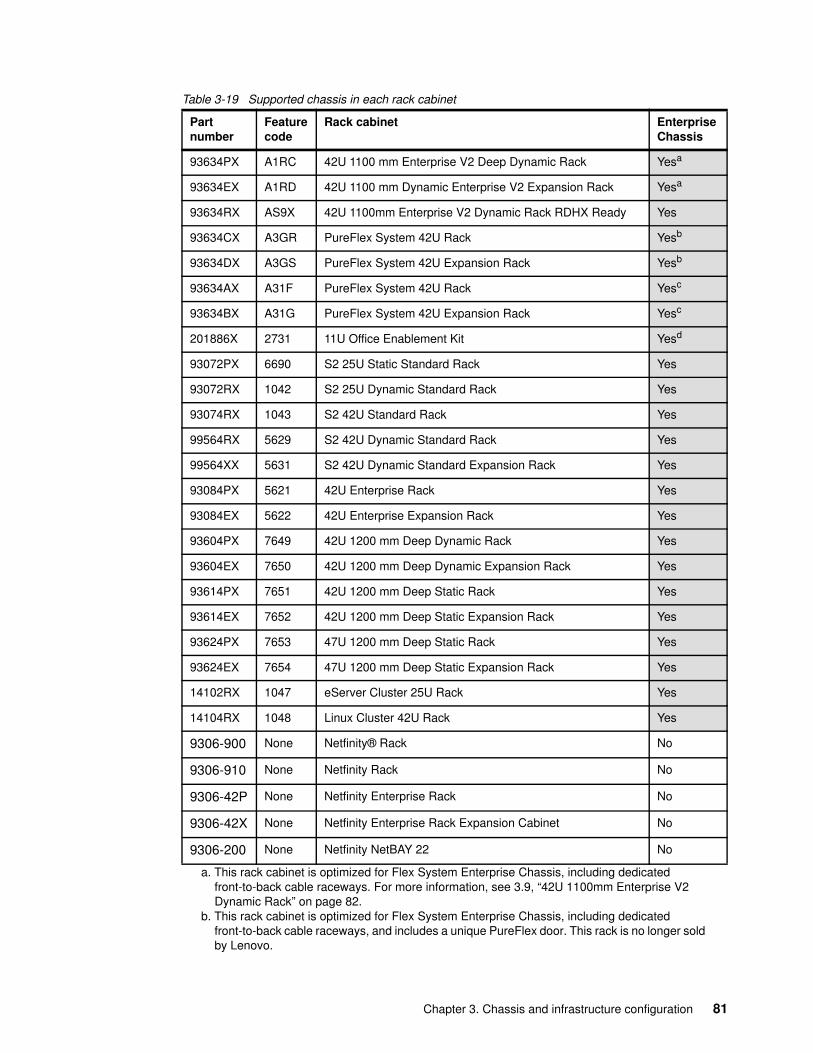
Table 3-19 Supported chassis in each rack cabinet
Partnumber
Featurecode
Rack cabinet Enterprise Chassis
93634PX A1RC 42U 1100 mm Enterprise V2 Deep Dynamic Rack Yesa
93634EX A1RD 42U 1100 mm Dynamic Enterprise V2 Expansion Rack Yesa
a. This rack cabinet is optimized for Flex System Enterprise Chassis, including dedicated front-to-back cable raceways. For more information, see 3.9, “42U 1100mm Enterprise V2 Dynamic Rack” on page 82.
93634RX AS9X 42U 1100mm Enterprise V2 Dynamic Rack RDHX Ready Yes
93634CX A3GR PureFlex System 42U Rack Yesb
93634DX A3GS PureFlex System 42U Expansion Rack Yesb
b. This rack cabinet is optimized for Flex System Enterprise Chassis, including dedicated front-to-back cable raceways, and includes a unique PureFlex door. This rack is no longer sold by Lenovo.
93634AX A31F PureFlex System 42U Rack Yesc
93634BX A31G PureFlex System 42U Expansion Rack Yesc
201886X 2731 11U Office Enablement Kit Yesd
93072PX 6690 S2 25U Static Standard Rack Yes
93072RX 1042 S2 25U Dynamic Standard Rack Yes
93074RX 1043 S2 42U Standard Rack Yes
99564RX 5629 S2 42U Dynamic Standard Rack Yes
99564XX 5631 S2 42U Dynamic Standard Expansion Rack Yes
93084PX 5621 42U Enterprise Rack Yes
93084EX 5622 42U Enterprise Expansion Rack Yes
93604PX 7649 42U 1200 mm Deep Dynamic Rack Yes
93604EX 7650 42U 1200 mm Deep Dynamic Expansion Rack Yes
93614PX 7651 42U 1200 mm Deep Static Rack Yes
93614EX 7652 42U 1200 mm Deep Static Expansion Rack Yes
93624PX 7653 47U 1200 mm Deep Static Rack Yes
93624EX 7654 47U 1200 mm Deep Static Expansion Rack Yes
14102RX 1047 eServer Cluster 25U Rack Yes
14104RX 1048 Linux Cluster 42U Rack Yes
9306-900 None Netfinity® Rack No
9306-910 None Netfinity Rack No
9306-42P None Netfinity Enterprise Rack No
9306-42X None Netfinity Enterprise Rack Expansion Cabinet No
9306-200 None Netfinity NetBAY 22 No
Chapter 3. Chassis and infrastructure configuration 81
Racks that have glass-fronted doors do not allow sufficient airflow for the Enterprise Chassis, such as the older Netfinity racks. In some cases with the Netfinity racks, the chassis depth is such that the Enterprise Chassis cannot be accommodated within the dimensions of the rack.
Further information on rack cabinets, including current and withdrawn models, can be found in the Lenovo Rack Cabinet Reference where specifications of Lenovo’s rack cabinets are listed:
https://lenovopress.com/lp0658-lenovo-rack-cabinet-reference
3.9 42U 1100mm Enterprise V2 Dynamic Rack
The 42U 1100mm Enterprise V2 Dynamic Rack is an industry-standard 19-inch (measured between mounting flanges) rack that supports the Enterprise Chassis, ThinkSystem, ThinkServer, System x servers, and options. It is available in primary or expansion form. The expansion rack is designed for baying and has no side panels. It ships with a baying kit. After it is attached to the side of a primary rack, the side panel that is removed from the primary rack is attached to the side of the expansion rack.
The available configurations are listed in Table 3-20.
Table 3-20 Rack options and part numbers
This 42U rack conforms to the EIA-310-D industry standard for a 19-inch, type A rack cabinet. The external rack dimensions are listed in Table 3-21.
Table 3-21 Dimensions of 42U 1100mm Enterprise V2 Dynamic Rack, 9363-4PX
c. This rack cabinet is optimized for Flex System Enterprise Chassis, including dedicated front-to-back cable raceways, and includes the original square blue design of unique PureFlex Logod Door, which was shipped Q2 - Q4, 2012. This rack is no longer sold by Lenovo.
d. This Office Enablement kit was designed for the BladeCenter S Chassis. The Flex System Enterprise Chassis can be installed within the 11U office enablement kit with 1U of space remaining; however, the acoustic footprint of a configuration is unlikely to be acceptable for office use. We recommend that an evaluation be performed before deployment in an office environment.
Model/Feature Code
Description Details Supports Rear Door Heat Exchanger (RDHX)
9363-4PX / A1RC 42U 1100mm Enterprise V2 Dynamic Rack
Rack ships with side panels and is stand-alone.
Yes
9363-4EX / A1RD 42U 1100mm Enterprise V2 Dynamic Expansion Rack
Rack ships with no side panels and is designed to attach to a primary rack, such as 9363-4PX or 9363-4RX.
Yes
9363-4RX / AS9X 42U 1100mm Enterprise V2 Dynamic Rack RDHX Ready
Rack ships with side panels and is stand-alone.
Yes. Packaging depth allows shipment from the manufacturing plant with a RDHX attached.
Dimension Value
Height 2009 mm (79.1 in.)
Width 600 mm (23.6 in.)
82 Lenovo Flex System Products and Technology
The rack features outriggers (stabilizers) that allow for movement and transportation while populated. These stabilizers are removed after the rack is installed.
The 42U 1100mm Enterprise V2 Dynamic Rack includes the following features:
� A perforated front door that allows for improved air flow
� Square EIA Rail mount points
� Six side-wall compartments that support 1U-high PDUs and switches without taking up valuable rack space
� Cable management rings that are included to help cable management
� Easy to install and remove side panels, which are a standard feature
� A front door that can be hinged on either side, which provides flexibility to open in either direction
� Front and rear doors and side panels that include locks and keys to help secure servers
� Heavy-duty casters with the use of outriggers (stabilizers) come with the 42U Dynamic racks for added stability, which allows movement of the rack while loaded
� Tool-less 0U PDU rear channel mounting, which reduces installation time and increases accessibility
� 1U PDU that can be mounted to present power outlets to the rear of the chassis in side pocket openings
� Removable top and bottom cable access panels in front and rear
Lenovo is a leading vendor with specific ship-loadable designs. These kinds of racks are called dynamic racks. The 42U 1100mm Enterprise V2 Dynamic Rack and 42U 1100mm Enterprise V2 Dynamic Expansion Rack are dynamic racks.
A dynamic rack features extra heavy-duty construction and sturdy packaging that can be reused for shipping a fully loaded rack. They also have outrigger casters for secure movement and tilt stability. Dynamic racks also include a heavy-duty shipping pallet that includes a ramp for easy “on and off” maneuvering. Dynamic racks undergo more shock and vibration testing, and all these racks are of welded rather than the less robust bolted construction.
The 9363-4RX / AS9X 42U 1100mm Enterprise V2 Dynamic Rack RDHX Ready, allows a RDHX to be fitted to the rear of a 42U Enterprise V2 Dynamic Rack when shipped. The packaging is deeper to allow this to be fitted and transported. The RDHX can be fitted to any Enterprise V2 Dynamic Rack, but only the RDHX Ready model can be shipped with a RDHX fitted to the rear.
Depth 1100 mm (43.3 in.)
Weight 174 kg (384 lb), including outriggers
Dimension Value
Chapter 3. Chassis and infrastructure configuration 83
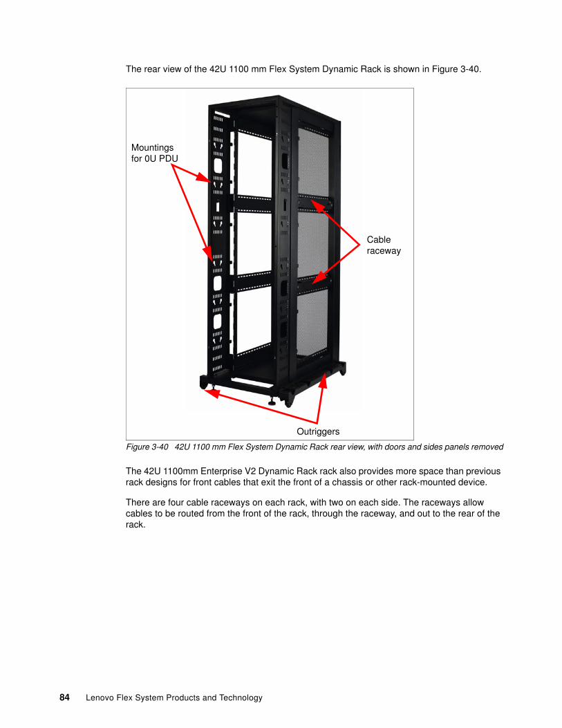
The rear view of the 42U 1100 mm Flex System Dynamic Rack is shown in Figure 3-40.
Figure 3-40 42U 1100 mm Flex System Dynamic Rack rear view, with doors and sides panels removed
The 42U 1100mm Enterprise V2 Dynamic Rack rack also provides more space than previous rack designs for front cables that exit the front of a chassis or other rack-mounted device.
There are four cable raceways on each rack, with two on each side. The raceways allow cables to be routed from the front of the rack, through the raceway, and out to the rear of the rack.
Cable raceway
Outriggers
Mountings for 0U PDU
84 Lenovo Flex System Products and Technology
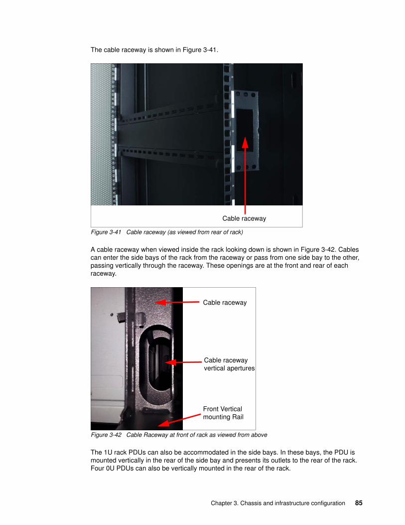
The cable raceway is shown in Figure 3-41.
Figure 3-41 Cable raceway (as viewed from rear of rack)
A cable raceway when viewed inside the rack looking down is shown in Figure 3-42. Cables can enter the side bays of the rack from the raceway or pass from one side bay to the other, passing vertically through the raceway. These openings are at the front and rear of each raceway.
Figure 3-42 Cable Raceway at front of rack as viewed from above
The 1U rack PDUs can also be accommodated in the side bays. In these bays, the PDU is mounted vertically in the rear of the side bay and presents its outlets to the rear of the rack. Four 0U PDUs can also be vertically mounted in the rear of the rack.
Cable raceway
Cable raceway
Front Vertical mounting Rail
Cable raceway vertical apertures
Chapter 3. Chassis and infrastructure configuration 85
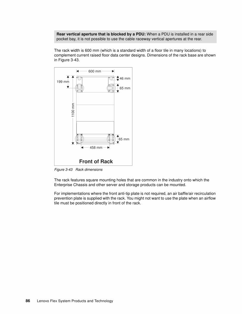
The rack width is 600 mm (which is a standard width of a floor tile in many locations) to complement current raised floor data center designs. Dimensions of the rack base are shown in Figure 3-43.
Figure 3-43 Rack dimensions
The rack features square mounting holes that are common in the industry onto which the Enterprise Chassis and other server and storage products can be mounted.
For implementations where the front anti-tip plate is not required, an air baffle/air recirculation prevention plate is supplied with the rack. You might not want to use the plate when an airflow tile must be positioned directly in front of the rack.
Rear vertical aperture that is blocked by a PDU: When a PDU is installed in a rear side pocket bay, it is not possible to use the cable raceway vertical apertures at the rear.
600 mm11
00 m
m
65 mm
65 mm
199 mm
Front of Rack
46 mm
458 mm
86 Lenovo Flex System Products and Technology
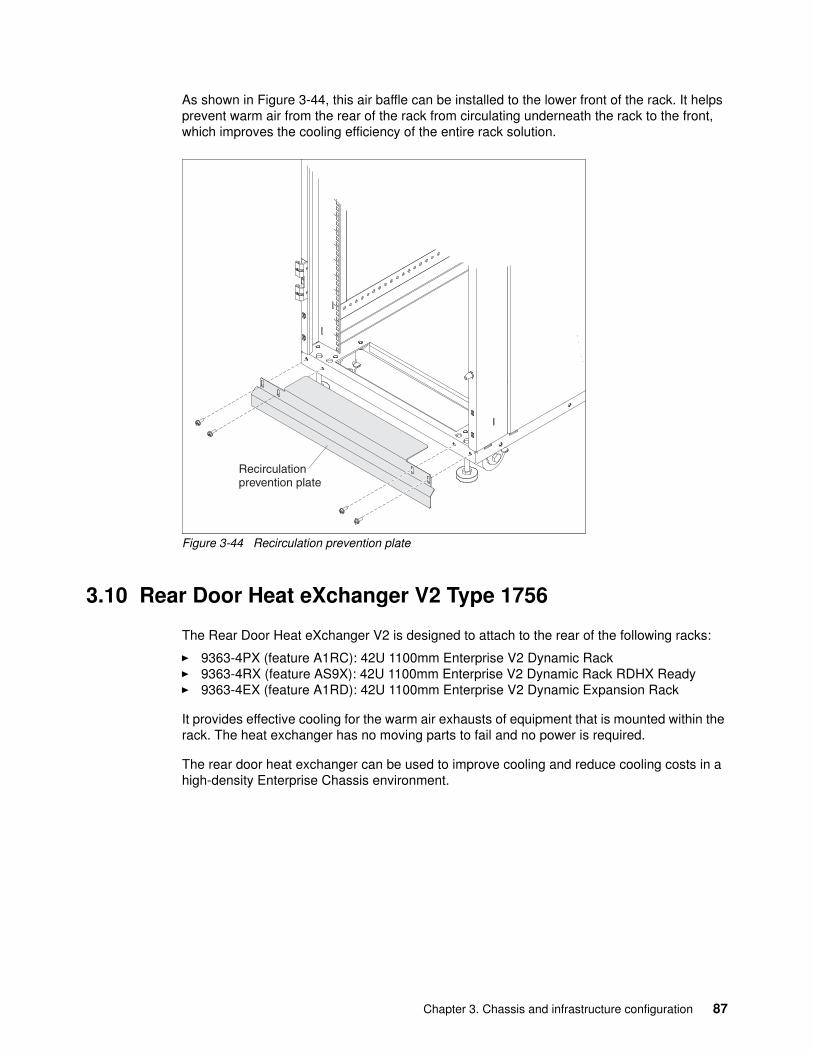
As shown in Figure 3-44, this air baffle can be installed to the lower front of the rack. It helps prevent warm air from the rear of the rack from circulating underneath the rack to the front, which improves the cooling efficiency of the entire rack solution.
Figure 3-44 Recirculation prevention plate
3.10 Rear Door Heat eXchanger V2 Type 1756
The Rear Door Heat eXchanger V2 is designed to attach to the rear of the following racks:
� 9363-4PX (feature A1RC): 42U 1100mm Enterprise V2 Dynamic Rack � 9363-4RX (feature AS9X): 42U 1100mm Enterprise V2 Dynamic Rack RDHX Ready� 9363-4EX (feature A1RD): 42U 1100mm Enterprise V2 Dynamic Expansion Rack
It provides effective cooling for the warm air exhausts of equipment that is mounted within the rack. The heat exchanger has no moving parts to fail and no power is required.
The rear door heat exchanger can be used to improve cooling and reduce cooling costs in a high-density Enterprise Chassis environment.
Recirculationprevention plate
Chapter 3. Chassis and infrastructure configuration 87
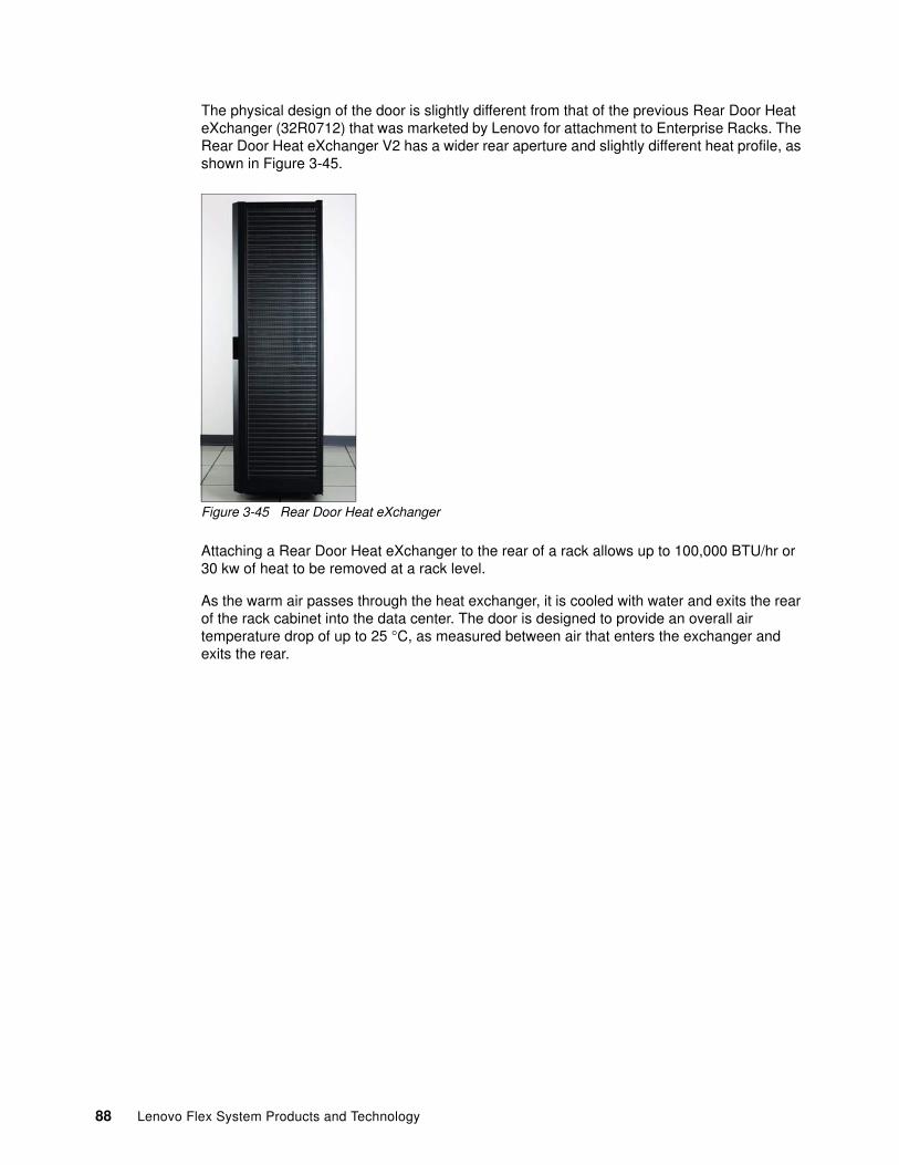
The physical design of the door is slightly different from that of the previous Rear Door Heat eXchanger (32R0712) that was marketed by Lenovo for attachment to Enterprise Racks. The Rear Door Heat eXchanger V2 has a wider rear aperture and slightly different heat profile, as shown in Figure 3-45.
Figure 3-45 Rear Door Heat eXchanger
Attaching a Rear Door Heat eXchanger to the rear of a rack allows up to 100,000 BTU/hr or 30 kw of heat to be removed at a rack level.
As the warm air passes through the heat exchanger, it is cooled with water and exits the rear of the rack cabinet into the data center. The door is designed to provide an overall air temperature drop of up to 25 °C, as measured between air that enters the exchanger and exits the rear.
88 Lenovo Flex System Products and Technology
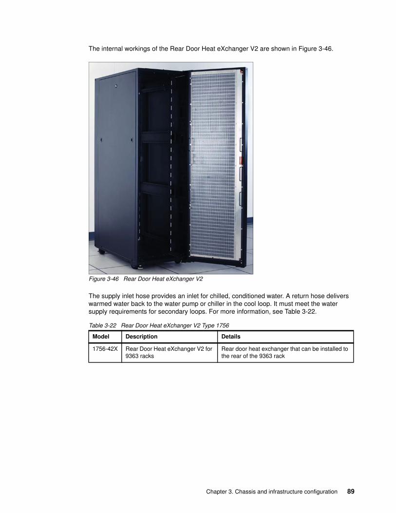
The internal workings of the Rear Door Heat eXchanger V2 are shown in Figure 3-46.
Figure 3-46 Rear Door Heat eXchanger V2
The supply inlet hose provides an inlet for chilled, conditioned water. A return hose delivers warmed water back to the water pump or chiller in the cool loop. It must meet the water supply requirements for secondary loops. For more information, see Table 3-22.
Table 3-22 Rear Door Heat eXchanger V2 Type 1756
Model Description Details
1756-42X Rear Door Heat eXchanger V2 for 9363 racks
Rear door heat exchanger that can be installed to the rear of the 9363 rack
Chapter 3. Chassis and infrastructure configuration 89
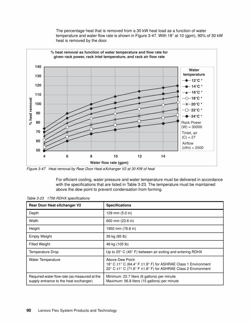
The percentage heat that is removed from a 30 kW heat load as a function of water temperature and water flow rate is shown in Figure 3-47. With 18° at 10 (gpm), 90% of 30 kW heat is removed by the door.
Figure 3-47 Heat removal by Rear Door Heat eXchanger V2 at 30 KW of heat
For efficient cooling, water pressure and water temperature must be delivered in accordance with the specifications that are listed in Table 3-23. The temperature must be maintained above the dew point to prevent condensation from forming.
Table 3-23 1756 RDHX specifications
140
130
120
110
100
90
80
70
60
50
% heat removal as function of water temperature and flow rate forgiven rack power, rack inlet temperature, and rack air flow rate
4 10 12 14
% h
eat
rem
oval
Water flow rate (gpm)
Watertemperature
12°C *
14°C *
16°C *
18°C *
20°C *
6 8
22°C *
24°C *
Airflow(cfm) = 2500
Rack Power(W) = 30000
Tinlet, air(C) = 27
Rear Door Heat eXchanger V2 Specifications
Depth 129 mm (5.0 in)
Width 600 mm (23.6 in)
Height 1950 mm (76.8 in)
Empty Weight 39 kg (85 lb)
Filled Weight 48 kg (105 lb)
Temperature Drop Up to 25° C (45° F) between air exiting and entering RDHX
Water Temperature Above Dew Point:18° C ±1° C (64.4° F ±1.8° F) for ASHRAE Class 1 Environment 22° C ±1° C (71.6° F ±1.8° F) for ASHRAE Class 2 Environment
Required water flow rate (as measured at the supply entrance to the heat exchanger)
Minimum: 22.7 liters (6 gallons) per minuteMaximum: 56.8 liters (15 gallons) per minute
90 Lenovo Flex System Products and Technology

The installation and planning guide provides lists of suppliers that can provide coolant distribution unit solutions, flexible hose assemblies, and water treatment that meet the suggested water quality requirements.
The Rear Door Heat eXchanger can be shipped in packaging when attached to the rear of a 9363-4RX/AS9X rack, or it can be attached to an existing rack in a data center. It takes three people to install the Rear Door Heat eXchanger to the rear of a rack. The exchanger requires a non-conductive step ladder to be used for attachment of the upper hinge assembly. Consult the Installation and Maintenance Guide before proceeding:
https://support.lenovo.com/docs/UM103398
Chapter 3. Chassis and infrastructure configuration 91

92 Lenovo Flex System Products and Technology
Chapter 4. I/O architecture and components
In this chapter, we describe the I/O architecture of the Enterprise Chassis, focusing on the I/O Modules and I/O Adapters that are interconnected across the midplane. We then cover the full range of I/O Modules that are inserted into the rear of the chassis. Finally, we review the various I/O Adapters that are installed into each node to provide interconnectivity.
The Flex System Carrier-Grade chassis I/O Architecture is identical to that of the Enterprise Chassis as described in this chapter; however, the Carrier-Grade supports only a subset of the I/O modules that are NEBS/ETSI certified.
This chapter includes the following topics:
� 4.1, “I/O architecture” on page 94� 4.2, “I/O modules” on page 102� 4.3, “I/O adapters” on page 173
4
© Copyright Lenovo 2018. All rights reserved. 93
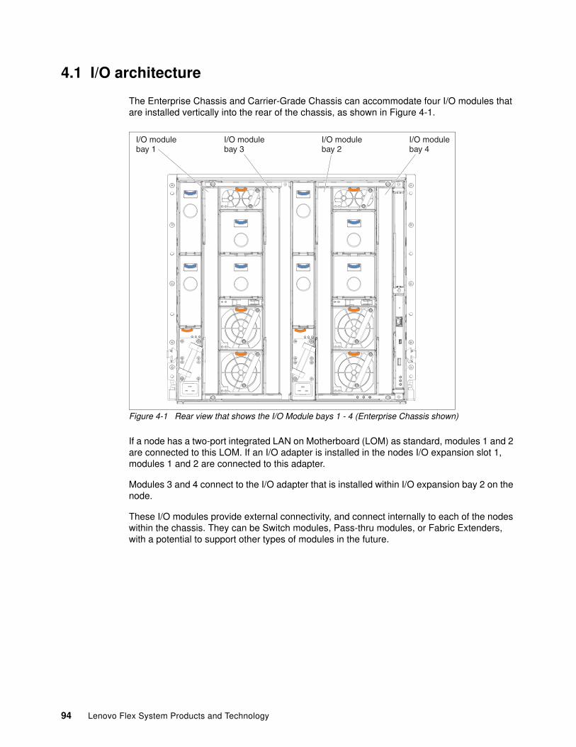
4.1 I/O architecture
The Enterprise Chassis and Carrier-Grade Chassis can accommodate four I/O modules that are installed vertically into the rear of the chassis, as shown in Figure 4-1.
Figure 4-1 Rear view that shows the I/O Module bays 1 - 4 (Enterprise Chassis shown)
If a node has a two-port integrated LAN on Motherboard (LOM) as standard, modules 1 and 2 are connected to this LOM. If an I/O adapter is installed in the nodes I/O expansion slot 1, modules 1 and 2 are connected to this adapter.
Modules 3 and 4 connect to the I/O adapter that is installed within I/O expansion bay 2 on the node.
These I/O modules provide external connectivity, and connect internally to each of the nodes within the chassis. They can be Switch modules, Pass-thru modules, or Fabric Extenders, with a potential to support other types of modules in the future.
I/O modulebay 1
I/O modulebay 3
I/O modulebay 2
I/O modulebay 4
94 Lenovo Flex System Products and Technology
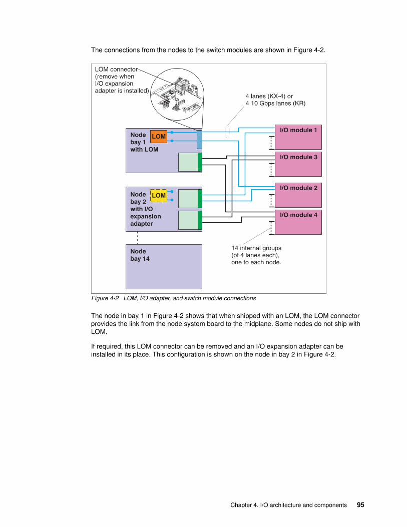
The connections from the nodes to the switch modules are shown in Figure 4-2.
Figure 4-2 LOM, I/O adapter, and switch module connections
The node in bay 1 in Figure 4-2 shows that when shipped with an LOM, the LOM connector provides the link from the node system board to the midplane. Some nodes do not ship with LOM.
If required, this LOM connector can be removed and an I/O expansion adapter can be installed in its place. This configuration is shown on the node in bay 2 in Figure 4-2.
Nodebay 1with LOM
Nodebay 2with I/Oexpansionadapter
Nodebay 14
LOM
LOM connector(remove whenI/O expansionadapter is installed)
I/O module 1
I/O module 3
I/O module 2
I/O module 4
LOM
4 lanes (KX-4) or4 10 Gbps lanes (KR)
14 internal groups(of 4 lanes each),one to each node.
Chapter 4. I/O architecture and components 95
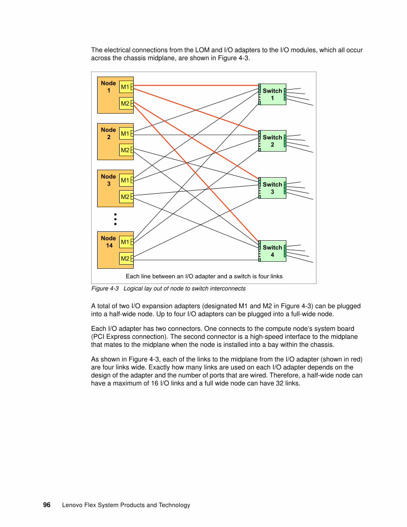
The electrical connections from the LOM and I/O adapters to the I/O modules, which all occur across the chassis midplane, are shown in Figure 4-3.
Figure 4-3 Logical lay out of node to switch interconnects
A total of two I/O expansion adapters (designated M1 and M2 in Figure 4-3) can be plugged into a half-wide node. Up to four I/O adapters can be plugged into a full-wide node.
Each I/O adapter has two connectors. One connects to the compute node’s system board (PCI Express connection). The second connector is a high-speed interface to the midplane that mates to the midplane when the node is installed into a bay within the chassis.
As shown in Figure 4-3, each of the links to the midplane from the I/O adapter (shown in red) are four links wide. Exactly how many links are used on each I/O adapter depends on the design of the adapter and the number of ports that are wired. Therefore, a half-wide node can have a maximum of 16 I/O links and a full wide node can have 32 links.
Node14 M1
M2
Node3 M1
M2
Node2 M1
M2
Node1 M1
M2
Switch1
Switch2
Switch3
Switch4
...
...
...
...
Each line between an I/O adapter and a switch is four links
96 Lenovo Flex System Products and Technology
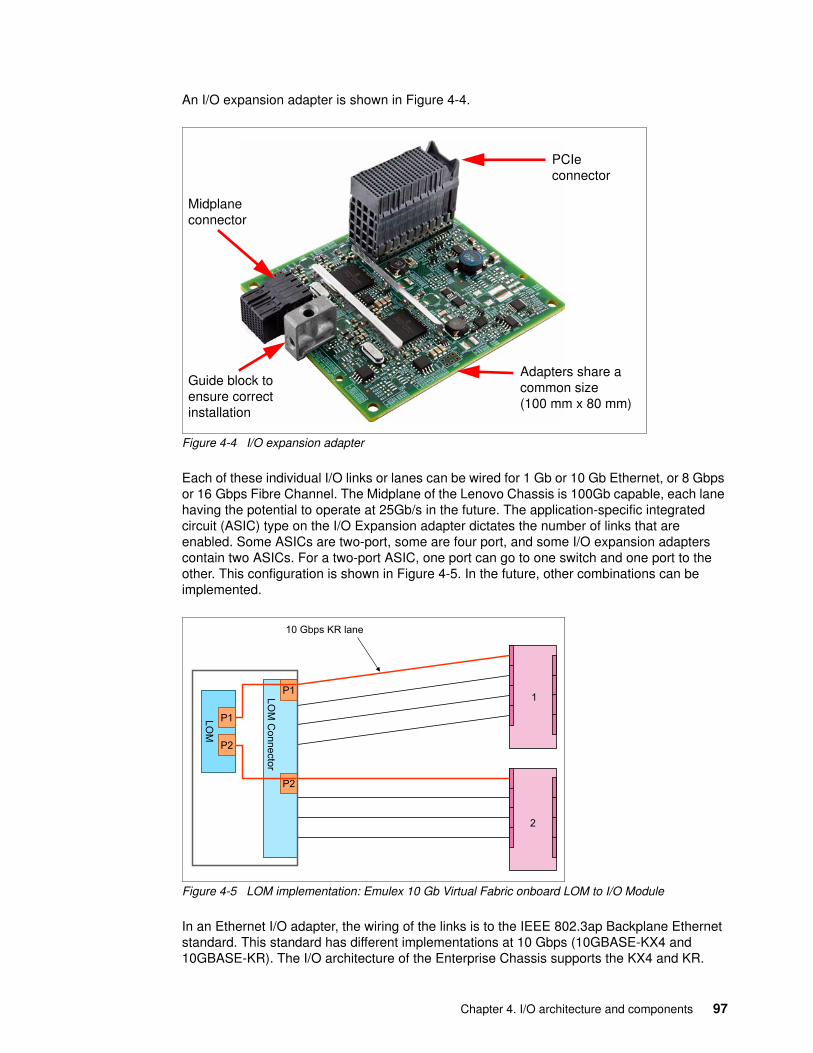
An I/O expansion adapter is shown in Figure 4-4.
Figure 4-4 I/O expansion adapter
Each of these individual I/O links or lanes can be wired for 1 Gb or 10 Gb Ethernet, or 8 Gbps or 16 Gbps Fibre Channel. The Midplane of the Lenovo Chassis is 100Gb capable, each lane having the potential to operate at 25Gb/s in the future. The application-specific integrated circuit (ASIC) type on the I/O Expansion adapter dictates the number of links that are enabled. Some ASICs are two-port, some are four port, and some I/O expansion adapters contain two ASICs. For a two-port ASIC, one port can go to one switch and one port to the other. This configuration is shown in Figure 4-5. In the future, other combinations can be implemented.
Figure 4-5 LOM implementation: Emulex 10 Gb Virtual Fabric onboard LOM to I/O Module
In an Ethernet I/O adapter, the wiring of the links is to the IEEE 802.3ap Backplane Ethernet standard. This standard has different implementations at 10 Gbps (10GBASE-KX4 and 10GBASE-KR). The I/O architecture of the Enterprise Chassis supports the KX4 and KR.
PCIe connector
Guide block to ensure correct installation
Midplane connector
Adapters share a common size (100 mm x 80 mm)
LOM
Connector
P1
P2
LOM
P2
P1
10 Gbps KR lane
1
2
Chapter 4. I/O architecture and components 97
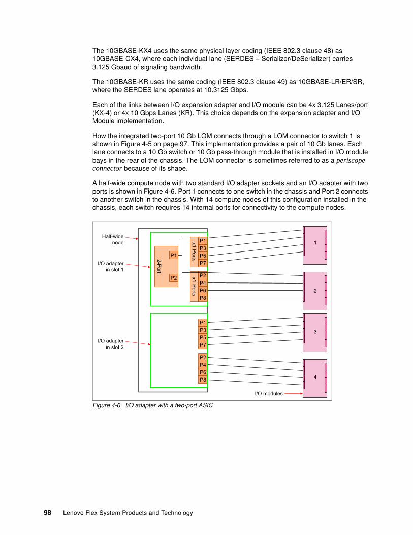
The 10GBASE-KX4 uses the same physical layer coding (IEEE 802.3 clause 48) as 10GBASE-CX4, where each individual lane (SERDES = Serializer/DeSerializer) carries 3.125 Gbaud of signaling bandwidth.
The 10GBASE-KR uses the same coding (IEEE 802.3 clause 49) as 10GBASE-LR/ER/SR, where the SERDES lane operates at 10.3125 Gbps.
Each of the links between I/O expansion adapter and I/O module can be 4x 3.125 Lanes/port (KX-4) or 4x 10 Gbps Lanes (KR). This choice depends on the expansion adapter and I/O Module implementation.
How the integrated two-port 10 Gb LOM connects through a LOM connector to switch 1 is shown in Figure 4-5 on page 97. This implementation provides a pair of 10 Gb lanes. Each lane connects to a 10 Gb switch or 10 Gb pass-through module that is installed in I/O module bays in the rear of the chassis. The LOM connector is sometimes referred to as a periscope connector because of its shape.
A half-wide compute node with two standard I/O adapter sockets and an I/O adapter with two ports is shown in Figure 4-6. Port 1 connects to one switch in the chassis and Port 2 connects to another switch in the chassis. With 14 compute nodes of this configuration installed in the chassis, each switch requires 14 internal ports for connectivity to the compute nodes.
Figure 4-6 I/O adapter with a two-port ASIC
P1P3P5P7
P2P4P6P8
x1 Ports
x1 Ports
P1P3P5P7
P2P4P6P8
2-Port
P1
P2
I/O adapter in slot 1
Half-widenode
I/O modules
I/O adapter in slot 2
1
2
3
4
98 Lenovo Flex System Products and Technology
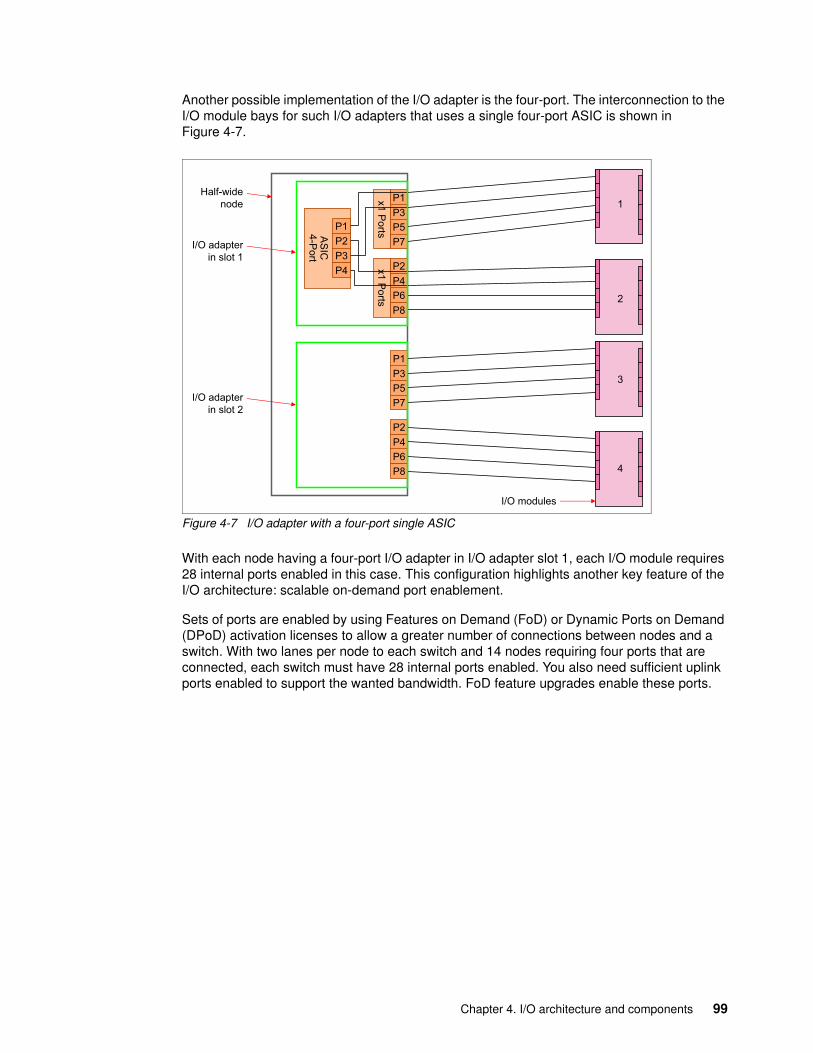
Another possible implementation of the I/O adapter is the four-port. The interconnection to the I/O module bays for such I/O adapters that uses a single four-port ASIC is shown in Figure 4-7.
Figure 4-7 I/O adapter with a four-port single ASIC
With each node having a four-port I/O adapter in I/O adapter slot 1, each I/O module requires 28 internal ports enabled in this case. This configuration highlights another key feature of the I/O architecture: scalable on-demand port enablement.
Sets of ports are enabled by using Features on Demand (FoD) or Dynamic Ports on Demand (DPoD) activation licenses to allow a greater number of connections between nodes and a switch. With two lanes per node to each switch and 14 nodes requiring four ports that are connected, each switch must have 28 internal ports enabled. You also need sufficient uplink ports enabled to support the wanted bandwidth. FoD feature upgrades enable these ports.
P1P3P5P7
P2P4P6P8
AS
IC4-P
ort
P1P3P5P7
x1 Ports
P2P4P6P8
x1 Ports
P1P2P3P4
I/O adapter in slot 1
Half-widenode
I/O modules
I/O adapter in slot 2
1
2
3
4
Chapter 4. I/O architecture and components 99
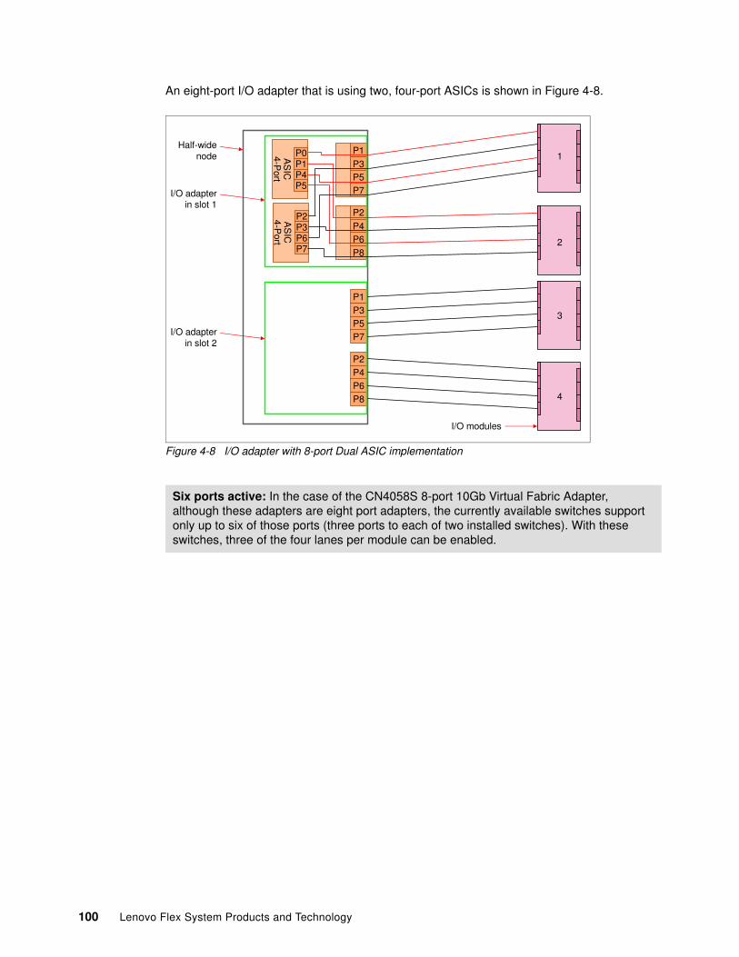
An eight-port I/O adapter that is using two, four-port ASICs is shown in Figure 4-8.
Figure 4-8 I/O adapter with 8-port Dual ASIC implementation
Six ports active: In the case of the CN4058S 8-port 10Gb Virtual Fabric Adapter, although these adapters are eight port adapters, the currently available switches support only up to six of those ports (three ports to each of two installed switches). With these switches, three of the four lanes per module can be enabled.
P1P3P5P7
P2P4P6P8
P1P3P5P7
P2
P4P6P8
I/O adapter in slot 1
Half-wide node
I/O modules
I/O adapter in slot 2
1
2
3
4
AS
IC4-P
ort
P2P3P6P7
AS
IC4-P
ort
P0P1P4P5
100 Lenovo Flex System Products and Technology
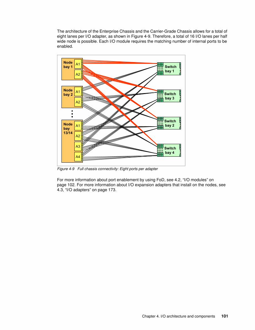
The architecture of the Enterprise Chassis and the Carrier-Grade Chassis allows for a total of eight lanes per I/O adapter, as shown in Figure 4-9. Therefore, a total of 16 I/O lanes per half wide node is possible. Each I/O module requires the matching number of internal ports to be enabled.
Figure 4-9 Full chassis connectivity: Eight ports per adapter
For more information about port enablement by using FoD, see 4.2, “I/O modules” on page 102. For more information about I/O expansion adapters that install on the nodes, see 4.3, “I/O adapters” on page 173.
Nodebay 2
Nodebay13/14
Switchbay 1
...
Switchbay 3
...
Switchbay 2
...
Switchbay 4
...
Nodebay 1
A1
A2
A1
A2
A1
A2
A3
A4
...
...
...
...
...
...
...
...
......
......
......
......
Chapter 4. I/O architecture and components 101
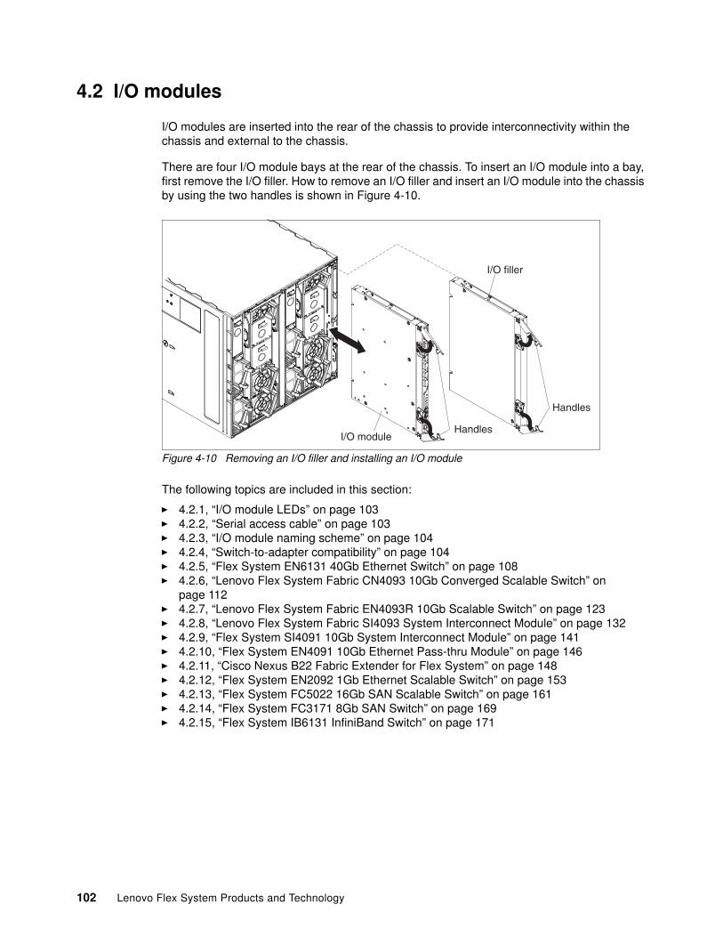
4.2 I/O modules
I/O modules are inserted into the rear of the chassis to provide interconnectivity within the chassis and external to the chassis.
There are four I/O module bays at the rear of the chassis. To insert an I/O module into a bay, first remove the I/O filler. How to remove an I/O filler and insert an I/O module into the chassis by using the two handles is shown in Figure 4-10.
Figure 4-10 Removing an I/O filler and installing an I/O module
The following topics are included in this section:
� 4.2.1, “I/O module LEDs” on page 103� 4.2.2, “Serial access cable” on page 103� 4.2.3, “I/O module naming scheme” on page 104� 4.2.4, “Switch-to-adapter compatibility” on page 104� 4.2.5, “Flex System EN6131 40Gb Ethernet Switch” on page 108� 4.2.6, “Lenovo Flex System Fabric CN4093 10Gb Converged Scalable Switch” on
page 112� 4.2.7, “Lenovo Flex System Fabric EN4093R 10Gb Scalable Switch” on page 123� 4.2.8, “Lenovo Flex System Fabric SI4093 System Interconnect Module” on page 132� 4.2.9, “Flex System SI4091 10Gb System Interconnect Module” on page 141� 4.2.10, “Flex System EN4091 10Gb Ethernet Pass-thru Module” on page 146� 4.2.11, “Cisco Nexus B22 Fabric Extender for Flex System” on page 148� 4.2.12, “Flex System EN2092 1Gb Ethernet Scalable Switch” on page 153� 4.2.13, “Flex System FC5022 16Gb SAN Scalable Switch” on page 161� 4.2.14, “Flex System FC3171 8Gb SAN Switch” on page 169� 4.2.15, “Flex System IB6131 InfiniBand Switch” on page 171
102 Lenovo Flex System Products and Technology
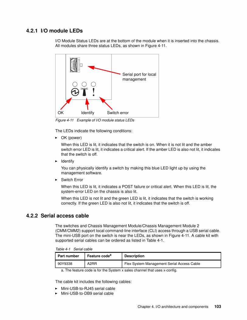
4.2.1 I/O module LEDs
I/O Module Status LEDs are at the bottom of the module when it is inserted into the chassis. All modules share three status LEDs, as shown in Figure 4-11.
Figure 4-11 Example of I/O module status LEDs
The LEDs indicate the following conditions:
� OK (power)
When this LED is lit, it indicates that the switch is on. When it is not lit and the amber switch error LED is lit, it indicates a critical alert. If the amber LED is also not lit, it indicates that the switch is off.
� Identify
You can physically identify a switch by making this blue LED light up by using the management software.
� Switch Error
When this LED is lit, it indicates a POST failure or critical alert. When this LED is lit, the system-error LED on the chassis is also lit.
When this LED is not lit and the green LED is lit, it indicates that the switch is working correctly. If the green LED is also not lit, it indicates that the switch is off.
4.2.2 Serial access cable
The switches and Chassis Management Module/Chassis Management Module 2 (CMM/CMM2) support local command-line interface (CLI) access through a USB serial cable. The mini-USB port on the switch is near the LEDs, as shown in Figure 4-11. A cable kit with supported serial cables can be ordered as listed in Table 4-1.
Table 4-1 Serial cable
The cable kit includes the following cables:
� Mini-USB-to-RJ45 serial cable � Mini-USB-to-DB9 serial cable
Switch errorIdentify OK
Serial port for local management
Part number Feature codea
a. The feature code is for the System x sales channel that uses x-config.
Description
90Y9338 A2RR Flex System Management Serial Access Cable
Chapter 4. I/O architecture and components 103
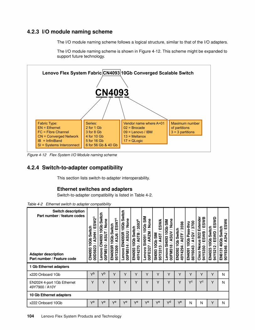
4.2.3 I/O module naming scheme
The I/O module naming scheme follows a logical structure, similar to that of the I/O adapters.
The I/O module naming scheme is shown in Figure 4-12. This scheme might be expanded to support future technology.
Figure 4-12 Flex System I/O Module naming scheme
4.2.4 Switch-to-adapter compatibility
This section lists switch-to-adapter interoperability.
Ethernet switches and adaptersSwitch-to-adapter compatibility is listed in Table 4-2.
Table 4-2 Ethernet switch to adapter compatibility
Lenovo Flex System Fabric CN4093 10Gb Converged Scalable Switch
CN4093
Fabric Type: EN = EthernetFC = Fibre ChannelCN = Converged NetworkIB = InfiniBandSI = Systems Interconnect
Vendor name where A=0102 = Brocade09 = Lenovo / IBM13 = Mellanox17 = QLogic
Maximum numberof partitions 3 = 3 partitions
Series:2 for 1 Gb3 for 8 Gb4 for 10 Gb5 for 16 Gb6 for 56 Gb & 40 Gb
Switch descriptionPart number / feature codes
CN
4093
10G
b S
witc
h00
D58
23 /
A3H
H /
ES
W2a
Leno
vo C
N40
93 1
0Gb
Sw
itch
00F
M51
0 / A
SU
T /
No
ne
EN
4093
R 1
0Gb
Sw
itch
95Y
3309
/ A
3J6
/ ES
W7a
Leno
vo E
N40
93R
10G
b S
witc
h00
FM
514
/ AS
UU
/ N
on
e
EN
4093
10G
b S
witc
h49
Y42
70 /
A0T
B /
3593
a
Len
ovo
SI4
091
10G
b S
IM00
FE
327
/ AR
ZM
/ N
on
e
SI4
093
10G
b S
IM95
Y33
13 /
A45
T /
ES
WA
Leno
vo S
I409
3 10
Gb
SIM
00F
M51
8 / A
SU
V /
No
ne
EN
2092
1G
b S
witc
h49
Y42
94 /
A0T
F /
3598
EN
4091
10G
b P
ass-
thru
88Y
6043
/ A
1QV
/ 37
00
Cis
co N
exus
B22
Ext
ende
r94
Y53
50 /
ES
WB
/ E
SW
B
EN
4023
10G
b S
witc
h94
Y52
12 /
ES
WD
/ E
SW
D
EN
6131
40G
b S
witc
h90
Y93
46 /
A3H
J / E
SW
6
Adapter descriptionPart number / Feature code
1 Gb Ethernet adapters
x220 Onboard 1Gb Yb Yb Y Y Y Y Y Y Y Y Y Y N
EN2024 4-port 1Gb Ethernet 49Y7900 / A10Y
Y Y Y Y Y Y Y Y Y Yc Yc Y N
10 Gb Ethernet adapters
x222 Onboard 10Gb Ye Ye Ye Ye Ye Ye Ye Yd Ye N N Y N
104 Lenovo Flex System Products and Technology
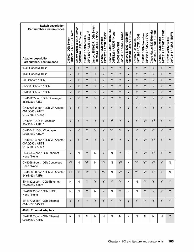
x240 Onboard 10Gb Y Y Y Y Y Y Y Y Y Y Y Y Y
x440 Onboard 10Gb Y Y Y Y Y Y Y Y Y Y Y Y Y
X6 Onboard 10Gb Y Y Y Y Y Y Y Y Y Y Y Y Y
SN550 Onboard 10Gb Y Y Y Y Y Y Y Y Y Y Y Y Y
SN850 Onboard 10Gb Y Y Y Y Y Y Y Y Y Y Y Y Y
CN4022 2-port 10Gb Converged88Y5920 / A4K3
Y Y Y Y Y Y Y Y Yf Y Y Y Y
CN4052S 2-port 10Gb VF Adapter00AG540 / ATBT 01CV780 / AU7X
Y Y Y Y Y Y Y Y Y Y Y Y Y
CN4054 10Gb VF Adapter90Y3554 / A1R1a
Y Y Y Y Y Yc Y Y Y Yc Yc Y Y
CN4054R 10Gb VF Adapter00Y3306 / A4K2a
Y Y Y Y Y Yc Y Y Y Yc Yc Y Y
CN4054S 4-port 10Gb VF Adapter00AG590 / ATBS 01CV790 / AU7Y
Y Y Y Y Y Yc Y Y Y Yc Yc Y Y
EN4054 4-port 10Gb EthernetNone / None
Y N Y N Y N Y N Y Yc Yc Y Y
CN4058 8-port 10Gb ConvergedNone / None
Yg N Yg N Yg N Yg N Yh Yc Yc Y N
CN4058S 8-port 10Gb VF Adapter94Y5160 / A4R6
Yg Y Yg Y Yg N Yg Y Yh Yc Yc Y N
EN4132 2-port 10 Gb Ethernet90Y3466 / A1QY
N N Y Y Y Y Y N N Y Y Y Y
EN4132 2-port 10Gb RoCENone / None
N N Y N Y N Y N N Y Y Y Y
EN4172 2-port 10Gb Ethernet00AG530 / A5RN
Y Y Y Y Y Y Y Y Y Y Y Y Y
40 Gb Ethernet adapters
EN6132 2-port 40Gb Ethernet90Y3482 / A3HK
N N N N N N N N N N N N Y
Switch descriptionPart number / feature codes
CN
4093
10G
b S
witc
h00
D58
23 /
A3H
H /
ES
W2a
Leno
vo C
N40
93 1
0Gb
Sw
itch
00F
M51
0 / A
SU
T /
No
ne
EN
4093
R 1
0Gb
Sw
itch
95Y
3309
/ A
3J6
/ ES
W7a
Leno
vo E
N40
93R
10G
b S
witc
h00
FM
514
/ AS
UU
/ N
on
e
EN
4093
10G
b S
witc
h49
Y42
70 /
A0T
B /
3593
a
Len
ovo
SI4
091
10G
b S
IM00
FE
327
/ AR
ZM
/ N
on
e
SI4
093
10G
b S
IM95
Y33
13 /
A45
T /
ES
WA
Leno
vo S
I409
3 10
Gb
SIM
00F
M51
8 / A
SU
V /
No
ne
EN
2092
1G
b S
witc
h49
Y42
94 /
A0T
F /
3598
EN
4091
10G
b P
ass-
thru
88Y
6043
/ A
1QV
/ 37
00
Cis
co N
exus
B22
Ext
ende
r94
Y53
50 /
ES
WB
/ E
SW
B
EN
4023
10G
b S
witc
h94
Y52
12 /
ES
WD
/ E
SW
D
EN
6131
40G
b S
witc
h90
Y93
46 /
A3H
J / E
SW
6
Adapter descriptionPart number / Feature code
Chapter 4. I/O architecture and components 105
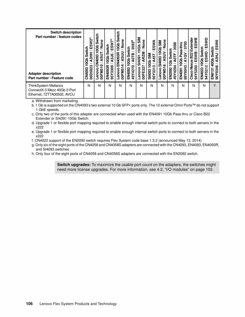
ThinkSystem Mellanox ConnectX-3 Mezz 40Gb 2-Port Ethernet, 7ZT7A00502, AVCU
N N N N N N N N N N N N Y
a. Withdrawn from marketingb. 1 Gb is supported on the CN4093’s two external 10 Gb SFP+ ports only. The 12 external Omni Ports™ do not support
1 GbE speeds.c. Only two of the ports of this adapter are connected when used with the EN4091 10Gb Pass-thru or Cisco B22
Extender or SI4091 10Gb Switch.d. Upgrade 1 or flexible port mapping required to enable enough internal switch ports to connect to both servers in the
x222e. Upgrade 1 or flexible port mapping required to enable enough internal switch ports to connect to both servers in the
x222f. CN4022 support of the EN2092 switch requires Flex System code base 1.3.2 (announced May 13, 2014)g. Only six of the eight ports of the CN4058 and CN4058S adapters are connected with the CN4093, EN4093, EN4093R,
and SI4093 switchesh. Only four of the eight ports of CN4058 and CN4058S adapters are connected with the EN2092 switch.
Switch descriptionPart number / feature codes
CN
4093
10G
b S
witc
h00
D58
23 /
A3H
H /
ES
W2a
Leno
vo C
N40
93 1
0Gb
Sw
itch
00F
M51
0 / A
SU
T /
No
ne
EN
4093
R 1
0Gb
Sw
itch
95Y
3309
/ A
3J6
/ ES
W7a
Leno
vo E
N40
93R
10G
b S
witc
h00
FM
514
/ AS
UU
/ N
on
e
EN
4093
10G
b S
witc
h49
Y42
70 /
A0T
B /
3593
a
Len
ovo
SI4
091
10G
b S
IM00
FE
327
/ AR
ZM
/ N
on
e
SI4
093
10G
b S
IM95
Y33
13 /
A45
T /
ES
WA
Leno
vo S
I409
3 10
Gb
SIM
00F
M51
8 / A
SU
V /
No
ne
EN
2092
1G
b S
witc
h49
Y42
94 /
A0T
F /
3598
EN
4091
10G
b P
ass-
thru
88Y
6043
/ A
1QV
/ 37
00
Cis
co N
exus
B22
Ext
ende
r94
Y53
50 /
ES
WB
/ E
SW
B
EN
4023
10G
b S
witc
h94
Y52
12 /
ES
WD
/ E
SW
D
EN
6131
40G
b S
witc
h90
Y93
46 /
A3H
J / E
SW
6
Adapter descriptionPart number / Feature code
Switch upgrades: To maximize the usable port count on the adapters, the switches might need more license upgrades. For more information, see 4.2, “I/O modules” on page 102.
106 Lenovo Flex System Products and Technology
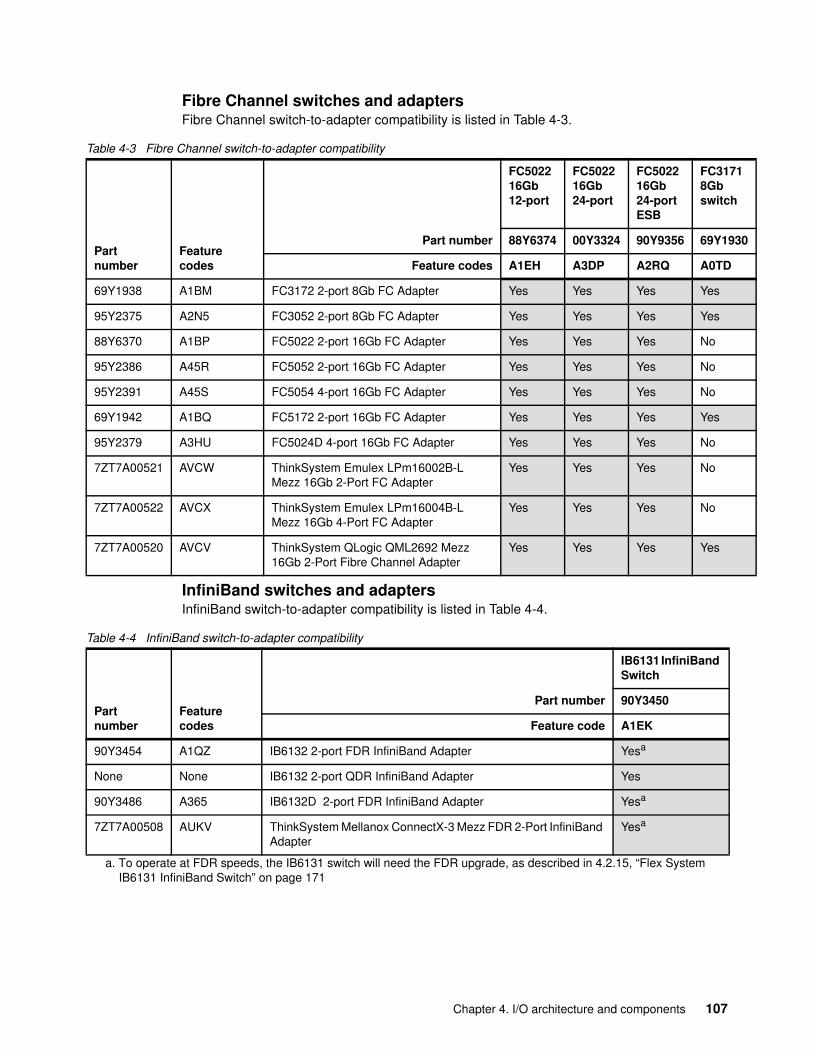
0
Fibre Channel switches and adaptersFibre Channel switch-to-adapter compatibility is listed in Table 4-3.
Table 4-3 Fibre Channel switch-to-adapter compatibility
InfiniBand switches and adaptersInfiniBand switch-to-adapter compatibility is listed in Table 4-4.
Table 4-4 InfiniBand switch-to-adapter compatibility
Partnumber
Featurecodes
Part number
FC502216Gb12-port
FC502216Gb24-port
FC502216Gb24-portESB
FC31718Gbswitch
88Y6374 00Y3324 90Y9356 69Y193
Feature codes A1EH A3DP A2RQ A0TD
69Y1938 A1BM FC3172 2-port 8Gb FC Adapter Yes Yes Yes Yes
95Y2375 A2N5 FC3052 2-port 8Gb FC Adapter Yes Yes Yes Yes
88Y6370 A1BP FC5022 2-port 16Gb FC Adapter Yes Yes Yes No
95Y2386 A45R FC5052 2-port 16Gb FC Adapter Yes Yes Yes No
95Y2391 A45S FC5054 4-port 16Gb FC Adapter Yes Yes Yes No
69Y1942 A1BQ FC5172 2-port 16Gb FC Adapter Yes Yes Yes Yes
95Y2379 A3HU FC5024D 4-port 16Gb FC Adapter Yes Yes Yes No
7ZT7A00521 AVCW ThinkSystem Emulex LPm16002B-L Mezz 16Gb 2-Port FC Adapter
Yes Yes Yes No
7ZT7A00522 AVCX ThinkSystem Emulex LPm16004B-L Mezz 16Gb 4-Port FC Adapter
Yes Yes Yes No
7ZT7A00520 AVCV ThinkSystem QLogic QML2692 Mezz 16Gb 2-Port Fibre Channel Adapter
Yes Yes Yes Yes
Partnumber
Featurecodes
Part number
IB6131 InfiniBand Switch
90Y3450
Feature code A1EK
90Y3454 A1QZ IB6132 2-port FDR InfiniBand Adapter Yesa
a. To operate at FDR speeds, the IB6131 switch will need the FDR upgrade, as described in 4.2.15, “Flex System IB6131 InfiniBand Switch” on page 171
None None IB6132 2-port QDR InfiniBand Adapter Yes
90Y3486 A365 IB6132D 2-port FDR InfiniBand Adapter Yesa
7ZT7A00508 AUKV ThinkSystem Mellanox ConnectX-3 Mezz FDR 2-Port InfiniBand Adapter
Yesa
Chapter 4. I/O architecture and components 107
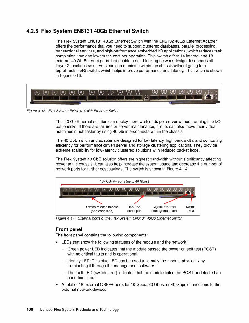
4.2.5 Flex System EN6131 40Gb Ethernet Switch
The Flex System EN6131 40Gb Ethernet Switch with the EN6132 40Gb Ethernet Adapter offers the performance that you need to support clustered databases, parallel processing, transactional services, and high-performance embedded I/O applications, which reduces task completion time and lowers the cost per operation. This switch offers 14 internal and 18 external 40 Gb Ethernet ports that enable a non-blocking network design. It supports all Layer 2 functions so servers can communicate within the chassis without going to a top-of-rack (ToR) switch, which helps improve performance and latency. The switch is shown in Figure 4-13.
Figure 4-13 Flex System EN6131 40Gb Ethernet Switch
This 40 Gb Ethernet solution can deploy more workloads per server without running into I/O bottlenecks. If there are failures or server maintenance, clients can also move their virtual machines much faster by using 40 Gb interconnects within the chassis.
The 40 GbE switch and adapter are designed for low latency, high bandwidth, and computing efficiency for performance-driven server and storage clustering applications. They provide extreme scalability for low-latency clustered solutions with reduced packet hops.
The Flex System 40 GbE solution offers the highest bandwidth without significantly affecting power to the chassis. It can also help increase the system usage and decrease the number of network ports for further cost savings. The switch is shown in Figure 4-14.
Figure 4-14 External ports of the Flex System EN6131 40Gb Ethernet Switch
Front panelThe front panel contains the following components:
� LEDs that show the following statuses of the module and the network:
– Green power LED indicates that the module passed the power-on self-test (POST) with no critical faults and is operational.
– Identify LED: This blue LED can be used to identify the module physically by illuminating it through the management software.
– The fault LED (switch error) indicates that the module failed the POST or detected an operational fault.
� A total of 18 external QSFP+ ports for 10 Gbps, 20 Gbps, or 40 Gbps connections to the external network devices.
18x QSFP+ ports (up to 40 Gbps)
Switch release handle (one each side)
Gigabit Ethernetmanagement port
SwitchLEDs
RS-232serial port
108 Lenovo Flex System Products and Technology
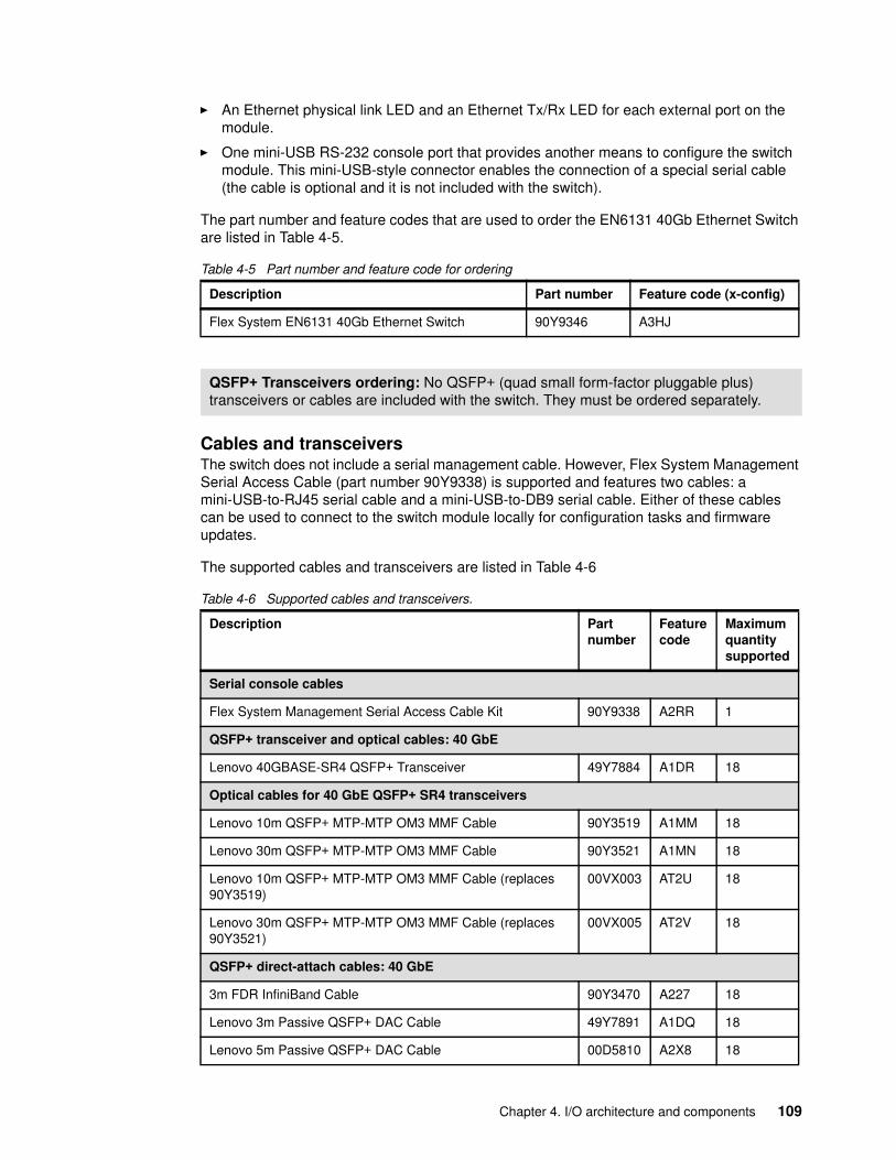
� An Ethernet physical link LED and an Ethernet Tx/Rx LED for each external port on the module.
� One mini-USB RS-232 console port that provides another means to configure the switch module. This mini-USB-style connector enables the connection of a special serial cable (the cable is optional and it is not included with the switch).
The part number and feature codes that are used to order the EN6131 40Gb Ethernet Switch are listed in Table 4-5.
Table 4-5 Part number and feature code for ordering
Cables and transceiversThe switch does not include a serial management cable. However, Flex System Management Serial Access Cable (part number 90Y9338) is supported and features two cables: a mini-USB-to-RJ45 serial cable and a mini-USB-to-DB9 serial cable. Either of these cables can be used to connect to the switch module locally for configuration tasks and firmware updates.
The supported cables and transceivers are listed in Table 4-6
Table 4-6 Supported cables and transceivers.
Description Part number Feature code (x-config)
Flex System EN6131 40Gb Ethernet Switch 90Y9346 A3HJ
QSFP+ Transceivers ordering: No QSFP+ (quad small form-factor pluggable plus) transceivers or cables are included with the switch. They must be ordered separately.
Description Partnumber
Featurecode
Maximumquantitysupported
Serial console cables
Flex System Management Serial Access Cable Kit 90Y9338 A2RR 1
QSFP+ transceiver and optical cables: 40 GbE
Lenovo 40GBASE-SR4 QSFP+ Transceiver 49Y7884 A1DR 18
Optical cables for 40 GbE QSFP+ SR4 transceivers
Lenovo 10m QSFP+ MTP-MTP OM3 MMF Cable 90Y3519 A1MM 18
Lenovo 30m QSFP+ MTP-MTP OM3 MMF Cable 90Y3521 A1MN 18
Lenovo 10m QSFP+ MTP-MTP OM3 MMF Cable (replaces 90Y3519)
00VX003 AT2U 18
Lenovo 30m QSFP+ MTP-MTP OM3 MMF Cable (replaces 90Y3521)
00VX005 AT2V 18
QSFP+ direct-attach cables: 40 GbE
3m FDR InfiniBand Cable 90Y3470 A227 18
Lenovo 3m Passive QSFP+ DAC Cable 49Y7891 A1DQ 18
Lenovo 5m Passive QSFP+ DAC Cable 00D5810 A2X8 18
Chapter 4. I/O architecture and components 109
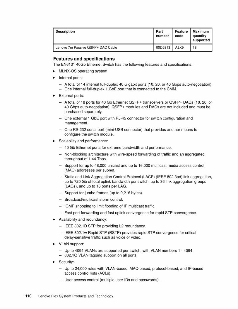
Features and specificationsThe EN6131 40Gb Ethernet Switch has the following features and specifications:
� MLNX-OS operating system
� Internal ports:
– A total of 14 internal full-duplex 40 Gigabit ports (10, 20, or 40 Gbps auto-negotiation).– One internal full-duplex 1 GbE port that is connected to the CMM.
� External ports:
– A total of 18 ports for 40 Gb Ethernet QSFP+ transceivers or QSFP+ DACs (10, 20, or 40 Gbps auto-negotiation). QSFP+ modules and DACs are not included and must be purchased separately.
– One external 1 GbE port with RJ-45 connector for switch configuration and management.
– One RS-232 serial port (mini-USB connector) that provides another means to configure the switch module.
� Scalability and performance:
– 40 Gb Ethernet ports for extreme bandwidth and performance.
– Non-blocking architecture with wire-speed forwarding of traffic and an aggregated throughput of 1.44 Tbps.
– Support for up to 48,000 unicast and up to 16,000 multicast media access control (MAC) addresses per subnet.
– Static and Link Aggregation Control Protocol (LACP) (IEEE 802.3ad) link aggregation, up to 720 Gb of total uplink bandwidth per switch, up to 36 link aggregation groups (LAGs), and up to 16 ports per LAG.
– Support for jumbo frames (up to 9,216 bytes).
– Broadcast/multicast storm control.
– IGMP snooping to limit flooding of IP multicast traffic.
– Fast port forwarding and fast uplink convergence for rapid STP convergence.
� Availability and redundancy:
– IEEE 802.1D STP for providing L2 redundancy.
– IEEE 802.1w Rapid STP (RSTP) provides rapid STP convergence for critical delay-sensitive traffic such as voice or video.
� VLAN support:
– Up to 4094 VLANs are supported per switch, with VLAN numbers 1 - 4094.– 802.1Q VLAN tagging support on all ports.
� Security:
– Up to 24,000 rules with VLAN-based, MAC-based, protocol-based, and IP-based access control lists (ACLs).
– User access control (multiple user IDs and passwords).
Lenovo 7m Passive QSFP+ DAC Cable 00D5813 A2X9 18
Description Partnumber
Featurecode
Maximumquantitysupported
110 Lenovo Flex System Products and Technology
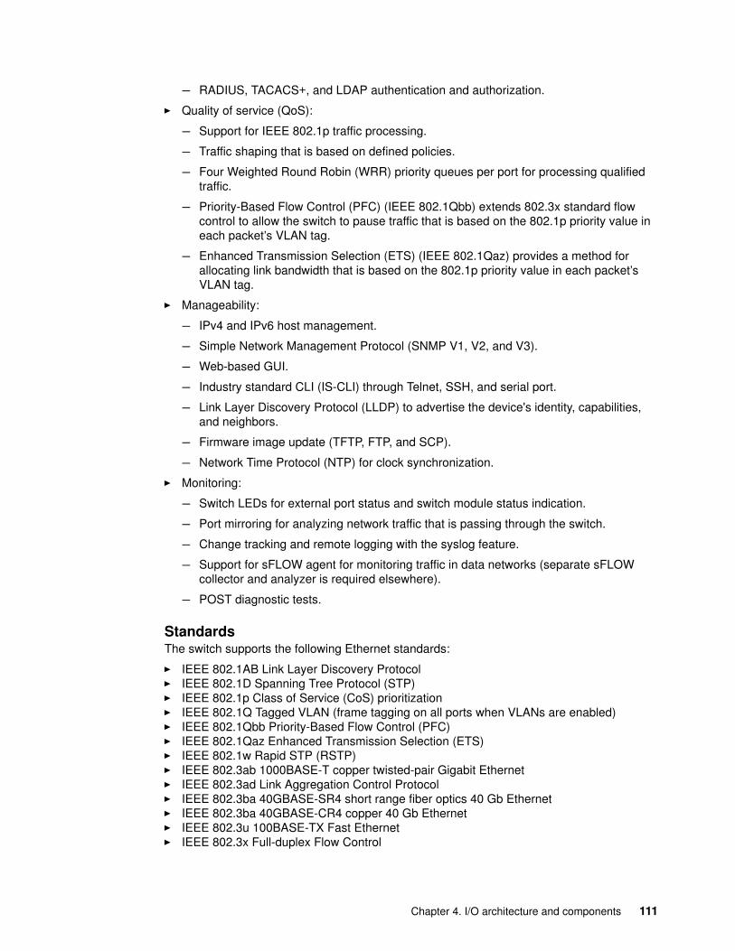
– RADIUS, TACACS+, and LDAP authentication and authorization.
� Quality of service (QoS):
– Support for IEEE 802.1p traffic processing.
– Traffic shaping that is based on defined policies.
– Four Weighted Round Robin (WRR) priority queues per port for processing qualified traffic.
– Priority-Based Flow Control (PFC) (IEEE 802.1Qbb) extends 802.3x standard flow control to allow the switch to pause traffic that is based on the 802.1p priority value in each packet’s VLAN tag.
– Enhanced Transmission Selection (ETS) (IEEE 802.1Qaz) provides a method for allocating link bandwidth that is based on the 802.1p priority value in each packet’s VLAN tag.
� Manageability:
– IPv4 and IPv6 host management.
– Simple Network Management Protocol (SNMP V1, V2, and V3).
– Web-based GUI.
– Industry standard CLI (IS-CLI) through Telnet, SSH, and serial port.
– Link Layer Discovery Protocol (LLDP) to advertise the device's identity, capabilities, and neighbors.
– Firmware image update (TFTP, FTP, and SCP).
– Network Time Protocol (NTP) for clock synchronization.
� Monitoring:
– Switch LEDs for external port status and switch module status indication.
– Port mirroring for analyzing network traffic that is passing through the switch.
– Change tracking and remote logging with the syslog feature.
– Support for sFLOW agent for monitoring traffic in data networks (separate sFLOW collector and analyzer is required elsewhere).
– POST diagnostic tests.
StandardsThe switch supports the following Ethernet standards:
� IEEE 802.1AB Link Layer Discovery Protocol� IEEE 802.1D Spanning Tree Protocol (STP)� IEEE 802.1p Class of Service (CoS) prioritization� IEEE 802.1Q Tagged VLAN (frame tagging on all ports when VLANs are enabled)� IEEE 802.1Qbb Priority-Based Flow Control (PFC)� IEEE 802.1Qaz Enhanced Transmission Selection (ETS)� IEEE 802.1w Rapid STP (RSTP)� IEEE 802.3ab 1000BASE-T copper twisted-pair Gigabit Ethernet� IEEE 802.3ad Link Aggregation Control Protocol� IEEE 802.3ba 40GBASE-SR4 short range fiber optics 40 Gb Ethernet� IEEE 802.3ba 40GBASE-CR4 copper 40 Gb Ethernet� IEEE 802.3u 100BASE-TX Fast Ethernet� IEEE 802.3x Full-duplex Flow Control
Chapter 4. I/O architecture and components 111
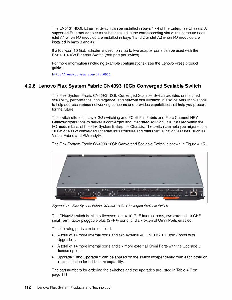
The EN6131 40Gb Ethernet Switch can be installed in bays 1 - 4 of the Enterprise Chassis. A supported Ethernet adapter must be installed in the corresponding slot of the compute node (slot A1 when I/O modules are installed in bays 1 and 2 or slot A2 when I/O modules are installed in bays 3 and 4).
If a four-port 10 GbE adapter is used, only up to two adapter ports can be used with the EN6131 40Gb Ethernet Switch (one port per switch).
For more information (including example configurations), see the Lenovo Press product guide:
http://lenovopress.com/tips0911
4.2.6 Lenovo Flex System Fabric CN4093 10Gb Converged Scalable Switch
The Flex System Fabric CN4093 10Gb Converged Scalable Switch provides unmatched scalability, performance, convergence, and network virtualization. It also delivers innovations to help address various networking concerns and provides capabilities that help you prepare for the future.
The switch offers full Layer 2/3 switching and FCoE Full Fabric and Fibre Channel NPV Gateway operations to deliver a converged and integrated solution. It is installed within the I/O module bays of the Flex System Enterprise Chassis. The switch can help you migrate to a 10 Gb or 40 Gb converged Ethernet infrastructure and offers virtualization features, such as Virtual Fabric and VMready®.
The Flex System Fabric CN4093 10Gb Converged Scalable Switch is shown in Figure 4-15.
Figure 4-15 Flex System Fabric CN4093 10 Gb Converged Scalable Switch
The CN4093 switch is initially licensed for 14 10-GbE internal ports, two external 10-GbE small form-factor pluggable plus (SFP+) ports, and six external Omni Ports enabled.
The following ports can be enabled:
� A total of 14 more internal ports and two external 40 GbE QSFP+ uplink ports with Upgrade 1.
� A total of 14 more internal ports and six more external Omni Ports with the Upgrade 2 license options.
� Upgrade 1 and Upgrade 2 can be applied on the switch independently from each other or in combination for full feature capability.
The part numbers for ordering the switches and the upgrades are listed in Table 4-7 on page 113.
112 Lenovo Flex System Products and Technology
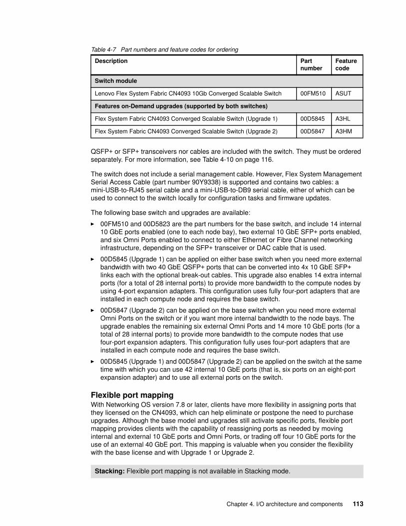
Table 4-7 Part numbers and feature codes for ordering
QSFP+ or SFP+ transceivers nor cables are included with the switch. They must be ordered separately. For more information, see Table 4-10 on page 116.
The switch does not include a serial management cable. However, Flex System Management Serial Access Cable (part number 90Y9338) is supported and contains two cables: a mini-USB-to-RJ45 serial cable and a mini-USB-to-DB9 serial cable, either of which can be used to connect to the switch locally for configuration tasks and firmware updates.
The following base switch and upgrades are available:
� 00FM510 and 00D5823 are the part numbers for the base switch, and include 14 internal 10 GbE ports enabled (one to each node bay), two external 10 GbE SFP+ ports enabled, and six Omni Ports enabled to connect to either Ethernet or Fibre Channel networking infrastructure, depending on the SFP+ transceiver or DAC cable that is used.
� 00D5845 (Upgrade 1) can be applied on either base switch when you need more external bandwidth with two 40 GbE QSFP+ ports that can be converted into 4x 10 GbE SFP+ links each with the optional break-out cables. This upgrade also enables 14 extra internal ports (for a total of 28 internal ports) to provide more bandwidth to the compute nodes by using 4-port expansion adapters. This configuration uses fully four-port adapters that are installed in each compute node and requires the base switch.
� 00D5847 (Upgrade 2) can be applied on the base switch when you need more external Omni Ports on the switch or if you want more internal bandwidth to the node bays. The upgrade enables the remaining six external Omni Ports and 14 more 10 GbE ports (for a total of 28 internal ports) to provide more bandwidth to the compute nodes that use four-port expansion adapters. This configuration fully uses four-port adapters that are installed in each compute node and requires the base switch.
� 00D5845 (Upgrade 1) and 00D5847 (Upgrade 2) can be applied on the switch at the same time with which you can use 42 internal 10 GbE ports (that is, six ports on an eight-port expansion adapter) and to use all external ports on the switch.
Flexible port mappingWith Networking OS version 7.8 or later, clients have more flexibility in assigning ports that they licensed on the CN4093, which can help eliminate or postpone the need to purchase upgrades. Although the base model and upgrades still activate specific ports, flexible port mapping provides clients with the capability of reassigning ports as needed by moving internal and external 10 GbE ports and Omni Ports, or trading off four 10 GbE ports for the use of an external 40 GbE port. This mapping is valuable when you consider the flexibility with the base license and with Upgrade 1 or Upgrade 2.
Description Partnumber
Featurecode
Switch module
Lenovo Flex System Fabric CN4093 10Gb Converged Scalable Switch 00FM510 ASUT
Features on-Demand upgrades (supported by both switches)
Flex System Fabric CN4093 Converged Scalable Switch (Upgrade 1) 00D5845 A3HL
Flex System Fabric CN4093 Converged Scalable Switch (Upgrade 2) 00D5847 A3HM
Stacking: Flexible port mapping is not available in Stacking mode.
Chapter 4. I/O architecture and components 113
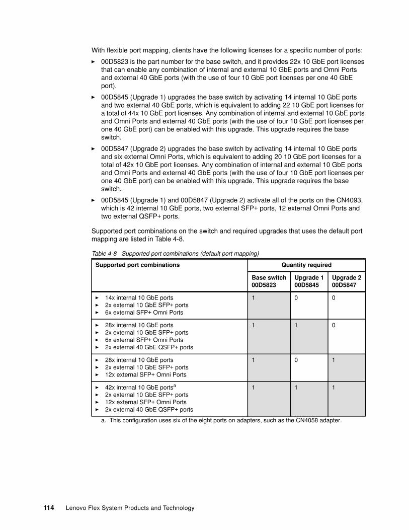
With flexible port mapping, clients have the following licenses for a specific number of ports:
� 00D5823 is the part number for the base switch, and it provides 22x 10 GbE port licenses that can enable any combination of internal and external 10 GbE ports and Omni Ports and external 40 GbE ports (with the use of four 10 GbE port licenses per one 40 GbE port).
� 00D5845 (Upgrade 1) upgrades the base switch by activating 14 internal 10 GbE ports and two external 40 GbE ports, which is equivalent to adding 22 10 GbE port licenses for a total of 44x 10 GbE port licenses. Any combination of internal and external 10 GbE ports and Omni Ports and external 40 GbE ports (with the use of four 10 GbE port licenses per one 40 GbE port) can be enabled with this upgrade. This upgrade requires the base switch.
� 00D5847 (Upgrade 2) upgrades the base switch by activating 14 internal 10 GbE ports and six external Omni Ports, which is equivalent to adding 20 10 GbE port licenses for a total of 42x 10 GbE port licenses. Any combination of internal and external 10 GbE ports and Omni Ports and external 40 GbE ports (with the use of four 10 GbE port licenses per one 40 GbE port) can be enabled with this upgrade. This upgrade requires the base switch.
� 00D5845 (Upgrade 1) and 00D5847 (Upgrade 2) activate all of the ports on the CN4093, which is 42 internal 10 GbE ports, two external SFP+ ports, 12 external Omni Ports and two external QSFP+ ports.
Supported port combinations on the switch and required upgrades that uses the default port mapping are listed in Table 4-8.
Table 4-8 Supported port combinations (default port mapping)
Supported port combinations Quantity required
Base switch00D5823
Upgrade 100D5845
Upgrade 200D5847
� 14x internal 10 GbE ports� 2x external 10 GbE SFP+ ports� 6x external SFP+ Omni Ports
1 0 0
� 28x internal 10 GbE ports� 2x external 10 GbE SFP+ ports� 6x external SFP+ Omni Ports� 2x external 40 GbE QSFP+ ports
1 1 0
� 28x internal 10 GbE ports� 2x external 10 GbE SFP+ ports� 12x external SFP+ Omni Ports
1 0 1
� 42x internal 10 GbE portsa
� 2x external 10 GbE SFP+ ports� 12x external SFP+ Omni Ports� 2x external 40 GbE QSFP+ ports
a. This configuration uses six of the eight ports on adapters, such as the CN4058 adapter.
1 1 1
114 Lenovo Flex System Products and Technology
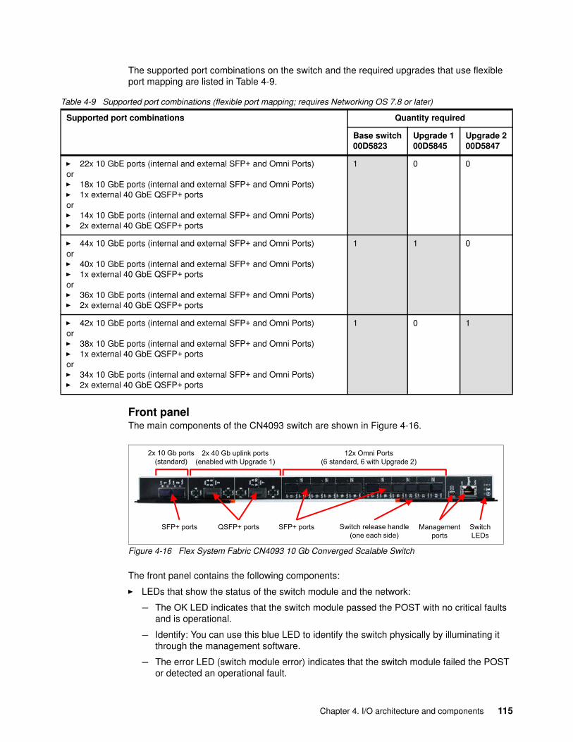
The supported port combinations on the switch and the required upgrades that use flexible port mapping are listed in Table 4-9.
Table 4-9 Supported port combinations (flexible port mapping; requires Networking OS 7.8 or later)
Front panelThe main components of the CN4093 switch are shown in Figure 4-16.
Figure 4-16 Flex System Fabric CN4093 10 Gb Converged Scalable Switch
The front panel contains the following components:
� LEDs that show the status of the switch module and the network:
– The OK LED indicates that the switch module passed the POST with no critical faults and is operational.
– Identify: You can use this blue LED to identify the switch physically by illuminating it through the management software.
– The error LED (switch module error) indicates that the switch module failed the POST or detected an operational fault.
Supported port combinations Quantity required
Base switch00D5823
Upgrade 100D5845
Upgrade 200D5847
� 22x 10 GbE ports (internal and external SFP+ and Omni Ports)or� 18x 10 GbE ports (internal and external SFP+ and Omni Ports)� 1x external 40 GbE QSFP+ portsor� 14x 10 GbE ports (internal and external SFP+ and Omni Ports)� 2x external 40 GbE QSFP+ ports
1 0 0
� 44x 10 GbE ports (internal and external SFP+ and Omni Ports)or� 40x 10 GbE ports (internal and external SFP+ and Omni Ports)� 1x external 40 GbE QSFP+ portsor� 36x 10 GbE ports (internal and external SFP+ and Omni Ports)� 2x external 40 GbE QSFP+ ports
1 1 0
� 42x 10 GbE ports (internal and external SFP+ and Omni Ports)or� 38x 10 GbE ports (internal and external SFP+ and Omni Ports)� 1x external 40 GbE QSFP+ portsor� 34x 10 GbE ports (internal and external SFP+ and Omni Ports)� 2x external 40 GbE QSFP+ ports
1 0 1
12x Omni Ports(6 standard, 6 with Upgrade 2)
2x 40 Gb uplink ports(enabled with Upgrade 1)
SFP+ ports Switch release handle (one each side)
QSFP+ ports Managementports
SwitchLEDs
2x 10 Gb ports(standard)
SFP+ ports
Chapter 4. I/O architecture and components 115
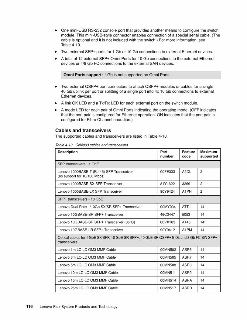
� One mini-USB RS-232 console port that provides another means to configure the switch module. This mini-USB-style connector enables connection of a special serial cable. (The cable is optional and it is not included with the switch.) For more information, see Table 4-10.
� Two external SFP+ ports for 1 Gb or 10 Gb connections to external Ethernet devices.
� A total of 12 external SFP+ Omni Ports for 10 Gb connections to the external Ethernet devices or 4/8 Gb FC connections to the external SAN devices.
� Two external QSFP+ port connectors to attach QSFP+ modules or cables for a single 40 Gb uplink per port or splitting of a single port into 4x 10 Gb connections to external Ethernet devices.
� A link OK LED and a Tx/Rx LED for each external port on the switch module.
� A mode LED for each pair of Omni Ports indicating the operating mode. (OFF indicates that the port pair is configured for Ethernet operation. ON indicates that the port pair is configured for Fibre Channel operation.)
Cables and transceiversThe supported cables and transceivers are listed in Table 4-10.
Table 4-10 CN4093 cables and transceivers
Omni Ports support: 1 Gb is not supported on Omni Ports.
Description Partnumber
Featurecode
Maximumsupported
SFP transceivers - 1 GbE
Lenovo 1000BASE-T (RJ-45) SFP Transceiver(no support for 10/100 Mbps)
00FE333 A5DL 2
Lenovo 1000BASE-SX SFP Transceiver 81Y1622 3269 2
Lenovo 1000BASE-LX SFP Transceiver 90Y9424 A1PN 2
SFP+ transceivers - 10 GbE
Lenovo Dual Rate 1/10Gb SX/SR SFP+ Transceiver 00MY034 ATTJ 14
Lenovo 10GBASE-SR SFP+ Transceiver 46C3447 5053 14
Lenovo 10GBASE-SR SFP+ Transceiver (85°C) 00VX183 AT45 14*
Lenovo 10GBASE-LR SFP+ Transceiver 90Y9412 A1PM 14
Optical cables for 1 GbE SX SFP, 10 GbE SR SFP+, 40 GbE SR QSFP+ BiDi, and 8 Gb FC SW SFP+ transceivers
Lenovo 1m LC-LC OM3 MMF Cable 00MN502 ASR6 14
Lenovo 3m LC-LC OM3 MMF Cable 00MN505 ASR7 14
Lenovo 5m LC-LC OM3 MMF Cable 00MN508 ASR8 14
Lenovo 10m LC-LC OM3 MMF Cable 00MN511 ASR9 14
Lenovo 15m LC-LC OM3 MMF Cable 00MN514 ASRA 14
Lenovo 25m LC-LC OM3 MMF Cable 00MN517 ASRB 14
116 Lenovo Flex System Products and Technology
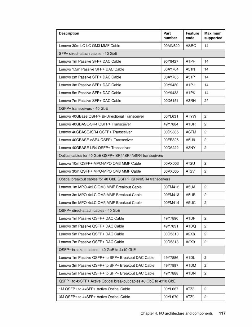
Lenovo 30m LC-LC OM3 MMF Cable 00MN520 ASRC 14
SFP+ direct-attach cables - 10 GbE
Lenovo 1m Passive SFP+ DAC Cable 90Y9427 A1PH 14
Lenovo 1.5m Passive SFP+ DAC Cable 00AY764 A51N 14
Lenovo 2m Passive SFP+ DAC Cable 00AY765 A51P 14
Lenovo 3m Passive SFP+ DAC Cable 90Y9430 A1PJ 14
Lenovo 5m Passive SFP+ DAC Cable 90Y9433 A1PK 14
Lenovo 7m Passive SFP+ DAC Cable 00D6151 A3RH 2a
QSFP+ transceivers - 40 GbE
Lenovo 40GBase QSFP+ Bi-Directional Transceiver 00YL631 ATYW 2
Lenovo 40GBASE-SR4 QSFP+ Transceiver 49Y7884 A1DR 2
Lenovo 40GBASE-iSR4 QSFP+ Transceiver 00D9865 ASTM 2
Lenovo 40GBASE-eSR4 QSFP+ Transceiver 00FE325 A5U9 2
Lenovo 40GBASE-LR4 QSFP+ Transceiver 00D6222 A3NY 2
Optical cables for 40 GbE QSFP+ SR4/iSR4/eSR4 transceivers
Lenovo 10m QSFP+ MPO-MPO OM3 MMF Cable 00VX003 AT2U 2
Lenovo 30m QSFP+ MPO-MPO OM3 MMF Cable 00VX005 AT2V 2
Optical breakout cables for 40 GbE QSFP+ iSR4/eSR4 transceivers
Lenovo 1m MPO-4xLC OM3 MMF Breakout Cable 00FM412 A5UA 2
Lenovo 3m MPO-4xLC OM3 MMF Breakout Cable 00FM413 A5UB 2
Lenovo 5m MPO-4xLC OM3 MMF Breakout Cable 00FM414 A5UC 2
QSFP+ direct-attach cables - 40 GbE
Lenovo 1m Passive QSFP+ DAC Cable 49Y7890 A1DP 2
Lenovo 3m Passive QSFP+ DAC Cable 49Y7891 A1DQ 2
Lenovo 5m Passive QSFP+ DAC Cable 00D5810 A2X8 2
Lenovo 7m Passive QSFP+ DAC Cable 00D5813 A2X9 2
QSFP+ breakout cables - 40 GbE to 4x10 GbE
Lenovo 1m Passive QSFP+ to SFP+ Breakout DAC Cable 49Y7886 A1DL 2
Lenovo 3m Passive QSFP+ to SFP+ Breakout DAC Cable 49Y7887 A1DM 2
Lenovo 5m Passive QSFP+ to SFP+ Breakout DAC Cable 49Y7888 A1DN 2
QSFP+ to 4xSFP+ Active Optical breakout cables 40 GbE to 4x10 GbE
1M QSFP+ to 4xSFP+ Active Optical Cable 00YL667 ATZ8 2
3M QSFP+ to 4xSFP+ Active Optical Cable 00YL670 ATZ9 2
Description Partnumber
Featurecode
Maximumsupported
Chapter 4. I/O architecture and components 117
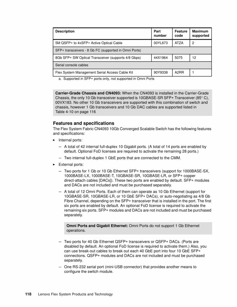
Features and specificationsThe Flex System Fabric CN4093 10Gb Converged Scalable Switch has the following features and specifications:
� Internal ports:
– A total of 42 internal full-duplex 10 Gigabit ports. (A total of 14 ports are enabled by default. Optional FoD licenses are required to activate the remaining 28 ports.)
– Two internal full-duplex 1 GbE ports that are connected to the CMM.
� External ports:
– Two ports for 1 Gb or 10 Gb Ethernet SFP+ transceivers (support for 1000BASE-SX, 1000BASE-LX, 1000BASE-T, 10GBASE-SR, 10GBASE-LR, or SFP+ copper direct-attach cables [DACs]). These two ports are enabled by default. SFP+ modules and DACs are not included and must be purchased separately.
– A total of 12 Omni Ports. Each of them can operate as 10 Gb Ethernet (support for 10GBASE-SR, 10GBASE-LR, or 10 GbE SFP+ DACs), or auto-negotiating as 4/8 Gb Fibre Channel, depending on the SFP+ transceiver that is installed in the port. The first six ports are enabled by default. An optional FoD license is required to activate the remaining six ports. SFP+ modules and DACs are not included and must be purchased separately.
– Two ports for 40 Gb Ethernet QSFP+ transceivers or QSFP+ DACs. (Ports are disabled by default. An optional FoD license is required to activate them.) Also, you can use break-out cables to break out each 40 GbE port into four 10 GbE SFP+ connections. QSFP+ modules and DACs are not included and must be purchased separately.
– One RS-232 serial port (mini-USB connector) that provides another means to configure the switch module.
5M QSFP+ to 4xSFP+ Active Optical Cable 00YL673 ATZA 2
SFP+ transceivers - 8 Gb FC (supported in Omni Ports)
8Gb SFP+ SW Optical Transceiver (supports 4/8 Gbps) 44X1964 5075 12
Serial console cables
Flex System Management Serial Access Cable Kit 90Y9338 A2RR 1
a. Supported in SFP+ ports only, not supported in Omni Ports
Carrier-Grade Chassis and CN4093: When the CN4093 is installed in the Carrier-Grade Chassis, the only 10 Gb transceiver supported is 10GBASE-SR SFP+ Transceiver (85° C), 00VX183. No other 10 Gb transceivers are supported with this combination of switch and chassis, however 1 Gb transceivers and 10 Gb DAC cables are supported listed in Table 4-10 on page 116
Omni Ports and Gigabit Ethernet: Omni Ports do not support 1 Gb Ethernet operations.
Description Partnumber
Featurecode
Maximumsupported
118 Lenovo Flex System Products and Technology
� Scalability and performance:
– 40 Gb Ethernet ports for extreme uplink bandwidth and performance.
– Fixed-speed external 10 Gb Ethernet ports to use the 10 Gb core infrastructure.
– Non-blocking architecture with wire-speed forwarding of traffic and aggregated throughput of 1.28 Tbps on Ethernet ports.
– Media access control (MAC) address learning: Automatic update and support for up to 128,000 MAC addresses.
– Up to 128 IP interfaces per switch.
– Static and LACP (IEEE 802.3ad) link aggregation; up to 220 Gb of total uplink bandwidth per switch, up to 64 trunk groups, and up to 16 ports per group.
– Support for jumbo frames (up to 9,216 bytes).
– Broadcast/multicast storm control.
– IGMP snooping to limit flooding of IP multicast traffic.
– IGMP filtering to control multicast traffic for hosts that participate in multicast groups.
– Configurable traffic distribution schemes over trunk links that are based on source or destination IP or MAC addresses, or both.
– Fast port forwarding and fast uplink convergence for rapid STP convergence.
� Availability and redundancy:
– Virtual Router Redundancy Protocol (VRRP) for Layer 3 router redundancy.
– IEEE 802.1D STP for providing L2 redundancy.
– IEEE 802.1s Multiple STP (MSTP) for topology optimization. Up to 32 STP instances are supported by a single switch.
– IEEE 802.1w Rapid STP (RSTP) provides rapid STP convergence for critical delay-sensitive traffic, such as voice or video.
– Per-VLAN Rapid STP (PVRST) enhancements.
– Layer 2 Trunk Failover to support active/standby configurations of network adapter teaming on compute nodes.
– Hot Links provides basic link redundancy with fast recovery for network topologies that require Spanning Tree to be turned off.
� VLAN support:
– Up to 1024 VLANs supported per switch, with VLAN numbers 1 - 4095 (4095 is used for management module’s connection only).
– 802.1Q VLAN tagging support on all ports.
– Private VLANs.
� Security:
– VLAN-based, MAC-based, and IP-based access control lists (ACLs)– 802.1x port-based authentication– Multiple user IDs and passwords– User access control– Radius, TACACS+, and LDAP authentication and authorization
� Quality of service (QoS):
– Support for IEEE 802.1p, IP ToS/DSCP, and ACL-based (MAC/IP source and destination addresses, VLANs) traffic classification and processing.
Chapter 4. I/O architecture and components 119
– Traffic shaping and remarking that is based on defined policies.
– Eight WRR priority queues per port for processing qualified traffic.
� IP v4 Layer 3 functions:
– Host management
– IP forwarding
– IP filtering with ACLs, with up to 896 ACLs supported
– VRRP for router redundancy
– Support for up to 128 static routes
– Routing protocol support (RIP v1, RIP v2, OSPF v2, and BGP-4), for up to 2048 entries in a routing table
– Support for DHCP Relay
– Support for IGMP snooping and IGMP relay
– Support for Protocol Independent Multicast (PIM) in Sparse Mode (PIM-SM) and Dense Mode (PIM-DM)
� IP v6 Layer 3 functions:
– IPv6 host management (except for a default switch management IP address)– IPv6 forwarding– Up to 128 static routes– Support for OSPF v3 routing protocol– IPv6 filtering with ACLs
� Virtualization:
– Virtual NICs (vNICs): Ethernet, iSCSI, or FCoE traffic is supported on vNICs.
– Unified fabric ports (UFPs): Ethernet or FCoE traffic is supported on UFPs.
– Virtual link aggregation groups (vLAGs).
– 802.1Qbg Edge Virtual Bridging (EVB) is an emerging IEEE standard for allowing networks to become virtual machine (VM)-aware:
• Virtual Ethernet Bridging (VEB) and Virtual Ethernet Port Aggregator (VEPA) are mechanisms for switching between VMs on the same hypervisor.
• Edge Control Protocol (ECP) is a transport protocol that operates between two peers over an IEEE 802 LAN that provides reliable and in-order delivery of upper layer protocol data units.
• Virtual Station Interface (VSI) Discovery and Configuration Protocol (VDP) allows centralized configuration of network policies that persists with the VM, independent of its location.
• EVB Type-Length-Value (TLV) is used to discover and configure VEPA, ECP, and VDP.
– VMready
� Switch partitioning (SPAR):
– SPAR forms separate virtual switching contexts by segmenting the data plane of the switch. Data plane traffic is not shared between SPARs on the same switch.
– SPAR operates as a Layer 2 broadcast network. Hosts on the same VLAN that are attached to a SPAR can communicate with each other and with the upstream switch. Hosts on the same VLAN (but are attached to different SPARs) communicate through the upstream switch.
120 Lenovo Flex System Products and Technology
– SPAR is implemented as a dedicated VLAN with a set of internal compute node ports and a single external port or link aggregation (LAG). Multiple external ports or LAGs are not allowed in SPAR. A port can be a member of only one SPAR.
� Converged Enhanced Ethernet:
– Priority-Based Flow Control (PFC) (IEEE 802.1Qbb) extends 802.3x standard flow control to allow the switch to pause traffic that is based on the 802.1p priority value in each packet’s VLAN tag.
– Enhanced Transmission Selection (ETS) (IEEE 802.1Qaz) provides a method for allocating link bandwidth that is based on the 802.1p priority value in each packet’s VLAN tag.
– Data center Bridging Capability Exchange Protocol (DCBX) (IEEE 802.1AB) allows neighboring network devices to exchange information about their capabilities.
� Fibre Channel over Ethernet (FCoE):
– FC-BB5 FCoE specification compliant– Native FC Forwarder switch operations– End-to-end FCoE support (initiator to target)– FCoE Initialization Protocol (FIP) support
� Fibre Channel:
– Omni Ports support 4/8 Gb FC when FC SFPs+ are installed in these ports.
– Full Fabric mode for end-to-end FCoE or NPV Gateway mode for external FC SAN attachments (support for B-type, Brocade, and Cisco MDS external SANs).
– Fabric services in Full Fabric mode:
• Name Server• Registered State Change Notification (RSCN)• Login services• Zoning
� Stacking:
– Hybrid stacking support (from two to six EN4093/EN4093R switches with two CN4093 switches)
– FCoE support
– FCoE LAG on external ports
– vNIC™ support
– 802.1Qbg support
� Manageability:
– Simple Network Management Protocol (SNMP V1, V2, and V3)– HTTP browser GUI– Telnet interface for CLI– SSH– Secure FTP (sFTP)– Service Location Protocol (SLP)– Serial interface for CLI– Scriptable CLI– Firmware image update (TFTP and FTP)– NTP for switch clock synchronization
� Monitoring:
– Switch LEDs for external port status and switch module status indication.
Chapter 4. I/O architecture and components 121
– Remote Monitoring (RMON) agent to collect statistics and proactively monitor switch performance.
– Port mirroring for analyzing network traffic that passes through a switch.
– Change tracking and remote logging with syslog feature.
– Support for sFLOW agent for monitoring traffic in data networks (separate sFLOW analyzer is required elsewhere).
– POST diagnostic tests.
The following features are not supported by IPv6:
� Default switch management IP address� SNMP trap host destination IP address� Bootstrap Protocol (BOOTP) and DHCP� RADIUS, TACACS+, and LDAP� QoS metering and remarking ACLs for out-profile traffic� VMware Virtual Center (vCenter) for VMready� Routing Information Protocol (RIP)� Internet Group Management Protocol (IGMP)� Border Gateway Protocol (BGP)� Virtual Router Redundancy Protocol (VRRP)� sFLOW
Standards supportedThe switches support the following standards:
� IEEE 802.1AB data center Bridging Capability Exchange Protocol (DCBX)� IEEE 802.1D Spanning Tree Protocol (STP)� IEEE 802.1p Class of Service (CoS) prioritization� IEEE 802.1s Multiple STP (MSTP)� IEEE 802.1Q Tagged VLAN (frame tagging on all ports when VLANs are enabled)� IEEE 802.1Qbg Edge Virtual Bridging� IEEE 802.1Qbb Priority-Based Flow Control (PFC)� IEEE 802.1Qaz Enhanced Transmission Selection (ETS)� IEEE 802.1x port-based authentication� IEEE 802.1w Rapid STP (RSTP)� IEEE 802.2 Logical Link Control� IEEE 802.3 10BASE-T Ethernet� IEEE 802.3ab 1000BASE-T copper twisted-pair Gigabit Ethernet� IEEE 802.3ad Link Aggregation Control Protocol� IEEE 802.3ae 10GBASE-SR short range fiber optics 10 Gb Ethernet� IEEE 802.3ae 10GBASE-LR long range fiber optics 10 Gb Ethernet� IEEE 802.3ba 40GBASE-SR4 short range fiber optics 40 Gb Ethernet� IEEE 802.3ba 40GBASE-CR4 copper 40 Gb Ethernet� IEEE 802.3u 100BASE-TX Fast Ethernet� IEEE 802.3x Full-duplex Flow Control � IEEE 802.3z 1000BASE-SX short range fiber optics Gigabit Ethernet� IEEE 802.3z 1000BASE-LX long range fiber optics Gigabit Ethernet� SFF-8431 10GSFP+Cu SFP+ Direct Attach Cable� FC-BB-5 FCoE
For more information, see the Lenovo Press product guide Flex System Fabric CN4093 10Gb Converged Scalable Switch, which is available from:
http://lenovopress.com/tips1293
122 Lenovo Flex System Products and Technology
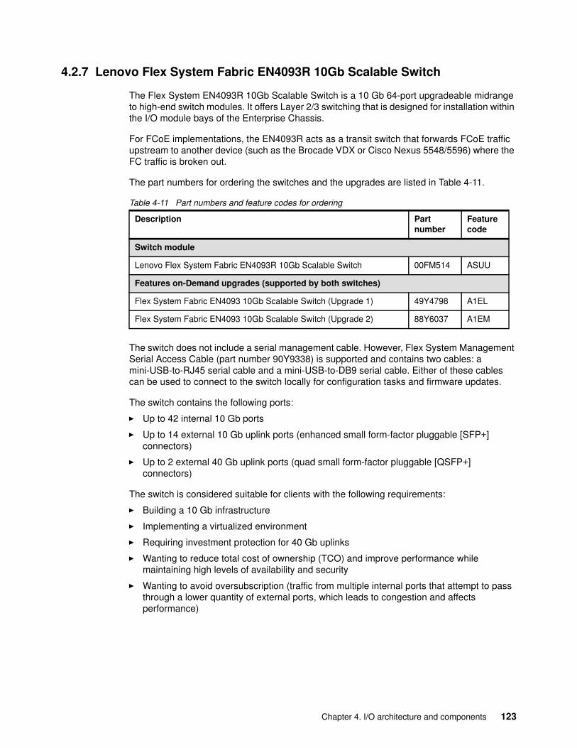
4.2.7 Lenovo Flex System Fabric EN4093R 10Gb Scalable Switch
The Flex System EN4093R 10Gb Scalable Switch is a 10 Gb 64-port upgradeable midrange to high-end switch modules. It offers Layer 2/3 switching that is designed for installation within the I/O module bays of the Enterprise Chassis.
For FCoE implementations, the EN4093R acts as a transit switch that forwards FCoE traffic upstream to another device (such as the Brocade VDX or Cisco Nexus 5548/5596) where the FC traffic is broken out.
The part numbers for ordering the switches and the upgrades are listed in Table 4-11.
Table 4-11 Part numbers and feature codes for ordering
The switch does not include a serial management cable. However, Flex System Management Serial Access Cable (part number 90Y9338) is supported and contains two cables: a mini-USB-to-RJ45 serial cable and a mini-USB-to-DB9 serial cable. Either of these cables can be used to connect to the switch locally for configuration tasks and firmware updates.
The switch contains the following ports:
� Up to 42 internal 10 Gb ports
� Up to 14 external 10 Gb uplink ports (enhanced small form-factor pluggable [SFP+] connectors)
� Up to 2 external 40 Gb uplink ports (quad small form-factor pluggable [QSFP+] connectors)
The switch is considered suitable for clients with the following requirements:
� Building a 10 Gb infrastructure
� Implementing a virtualized environment
� Requiring investment protection for 40 Gb uplinks
� Wanting to reduce total cost of ownership (TCO) and improve performance while maintaining high levels of availability and security
� Wanting to avoid oversubscription (traffic from multiple internal ports that attempt to pass through a lower quantity of external ports, which leads to congestion and affects performance)
Description Partnumber
Featurecode
Switch module
Lenovo Flex System Fabric EN4093R 10Gb Scalable Switch 00FM514 ASUU
Features on-Demand upgrades (supported by both switches)
Flex System Fabric EN4093 10Gb Scalable Switch (Upgrade 1) 49Y4798 A1EL
Flex System Fabric EN4093 10Gb Scalable Switch (Upgrade 2) 88Y6037 A1EM
Chapter 4. I/O architecture and components 123
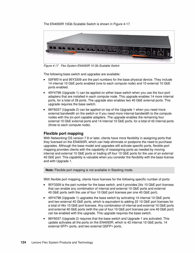
The EN4093R 10Gb Scalable Switch is shown in Figure 4-17.
Figure 4-17 Flex System EN4093R 10 Gb Scalable Switch
The following base switch and upgrades are available:
� 00FM514 and 95Y3309 are the part numbers for the base physical device. They include 14 internal 10 GbE ports enabled (one to each compute node) and 10 external 10 GbE ports enabled.
� 49Y4798 (Upgrade 1) can be applied on either base switch when you use the four-port adapters that are installed in each compute node. This upgrade enables 14 more internal ports, for a total of 28 ports. The upgrade also enables two 40 GbE external ports. This upgrade requires the base switch.
� 88Y6037 (Upgrade 2) can be applied on top of the Upgrade 1 when you need more external bandwidth on the switch or if you need more internal bandwidth to the compute nodes with the six-port capable adapters. The upgrade enables the remaining four external 10 GbE external ports and 14 internal 10 GbE ports, for a total of 42 internal ports (three to each compute node).
Flexible port mappingWith Networking OS version 7.8 or later, clients have more flexibility in assigning ports that they licensed on the EN4093R, which can help eliminate or postpone the need to purchase upgrades. Although the base model and upgrades still activate specific ports, flexible port mapping provides clients with the capability of reassigning ports as needed by moving internal and external 10 GbE ports or trading off four 10 GbE ports for the use of an external 40 GbE port. This capability is valuable when you consider the flexibility with the base license and with Upgrade 1.
With flexible port mapping, clients have licenses for the following specific number of ports:
� 95Y3309 is the part number for the base switch, and it provides 24x 10 GbE port licenses that can enable any combination of internal and external 10 GbE ports and external 40 GbE ports (with the use of four 10 GbE port licenses per one 40 GbE port).
� 49Y4798 (Upgrade 1) upgrades the base switch by activating 14 internal 10 GbE ports and two external 40 GbE ports, which is equivalent to adding 22 10 GbE port licenses for a total of 46x 10 GbE port licenses. Any combination of internal and external 10 GbE ports and external 40 GbE ports (with the use of four 10 GbE port licenses per one 40 GbE port) can be enabled with this upgrade. This upgrade requires the base switch.
� 88Y6037 (Upgrade 2) requires that the base switch and Upgrade 1 are activated. This update activates all the ports on the EN4093R, which is 42 internal 10 GbE ports, 14 external SFP+ ports, and two external QSFP+ ports.
Note: Flexible port mapping is not available in Stacking mode.
124 Lenovo Flex System Products and Technology
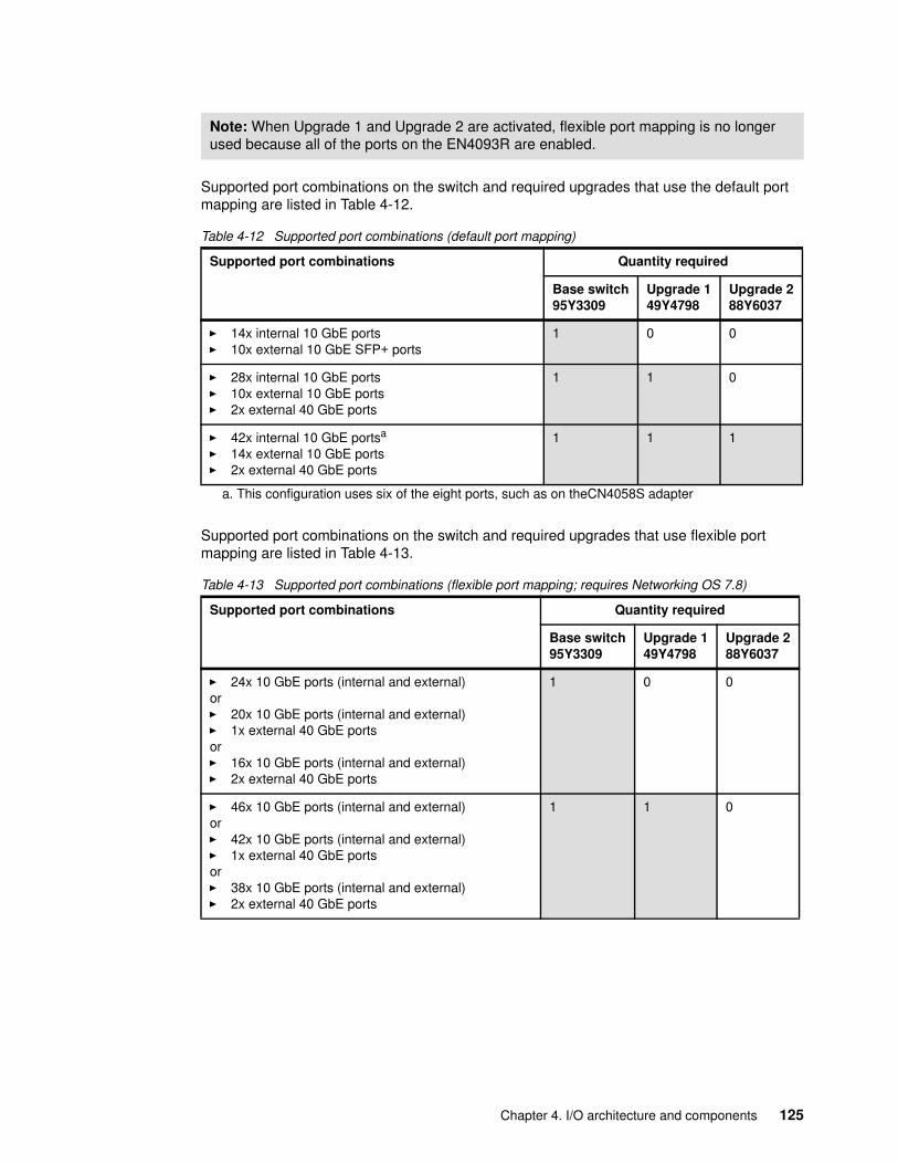
Supported port combinations on the switch and required upgrades that use the default port mapping are listed in Table 4-12.
Table 4-12 Supported port combinations (default port mapping)
Supported port combinations on the switch and required upgrades that use flexible port mapping are listed in Table 4-13.
Table 4-13 Supported port combinations (flexible port mapping; requires Networking OS 7.8)
Note: When Upgrade 1 and Upgrade 2 are activated, flexible port mapping is no longer used because all of the ports on the EN4093R are enabled.
Supported port combinations Quantity required
Base switch95Y3309
Upgrade 149Y4798
Upgrade 288Y6037
� 14x internal 10 GbE ports� 10x external 10 GbE SFP+ ports
1 0 0
� 28x internal 10 GbE ports� 10x external 10 GbE ports� 2x external 40 GbE ports
1 1 0
� 42x internal 10 GbE portsa
� 14x external 10 GbE ports� 2x external 40 GbE ports
a. This configuration uses six of the eight ports, such as on theCN4058S adapter
1 1 1
Supported port combinations Quantity required
Base switch95Y3309
Upgrade 149Y4798
Upgrade 288Y6037
� 24x 10 GbE ports (internal and external)or� 20x 10 GbE ports (internal and external)� 1x external 40 GbE portsor� 16x 10 GbE ports (internal and external)� 2x external 40 GbE ports
1 0 0
� 46x 10 GbE ports (internal and external)or� 42x 10 GbE ports (internal and external)� 1x external 40 GbE portsor� 38x 10 GbE ports (internal and external)� 2x external 40 GbE ports
1 1 0
Chapter 4. I/O architecture and components 125
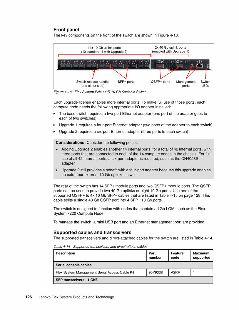
Front panelThe key components on the front of the switch are shown in Figure 4-18.
Figure 4-18 Flex System EN4093R 10 Gb Scalable Switch
Each upgrade license enables more internal ports. To make full use of those ports, each compute node needs the following appropriate I/O adapter installed:
� The base switch requires a two-port Ethernet adapter (one port of the adapter goes to each of two switches)
� Upgrade 1 requires a four-port Ethernet adapter (two ports of the adapter to each switch)
� Upgrade 2 requires a six-port Ethernet adapter (three ports to each switch)
The rear of the switch has 14 SFP+ module ports and two QSFP+ module ports. The QSFP+ ports can be used to provide two 40 Gb uplinks or eight 10 Gb ports. Use one of the supported QSFP+ to 4x 10 Gb SFP+ cables that are listed in Table 4-15 on page 128. This cable splits a single 40 Gb QSFP port into 4 SFP+ 10 Gb ports.
The switch is designed to function with nodes that contain a 1Gb LOM, such as the Flex System x220 Compute Node.
To manage the switch, a mini USB port and an Ethernet management port are provided.
Supported cables and transceiversThe supported transceivers and direct-attached cables for the switch are listed in Table 4-14.
Table 4-14 Supported transceivers and direct-attach cables
Considerations: Consider the following points:
� Adding Upgrade 2 enables another 14 internal ports, for a total of 42 internal ports, with three ports that are connected to each of the 14 compute nodes in the chassis. For full use of all 42 internal ports, a six-port adapter is required, such as the CN4058S adapter.
� Upgrade 2 still provides a benefit with a four-port adapter because this upgrade enables an extra four external 10 Gb uplinks as well.
Description Part number
Feature code
Maximum supported
Serial console cables
Flex System Management Serial Access Cable Kit 90Y9338 A2RR 1
SFP transceivers - 1 GbE
14x 10 Gb uplink ports (10 standard, 4 with Upgrade 2)
2x 40 Gb uplink ports (enabled with Upgrade 1)
SFP+ portsSwitch release handle (one either side)
QSFP+ ports Managementports
SwitchLEDs
126 Lenovo Flex System Products and Technology
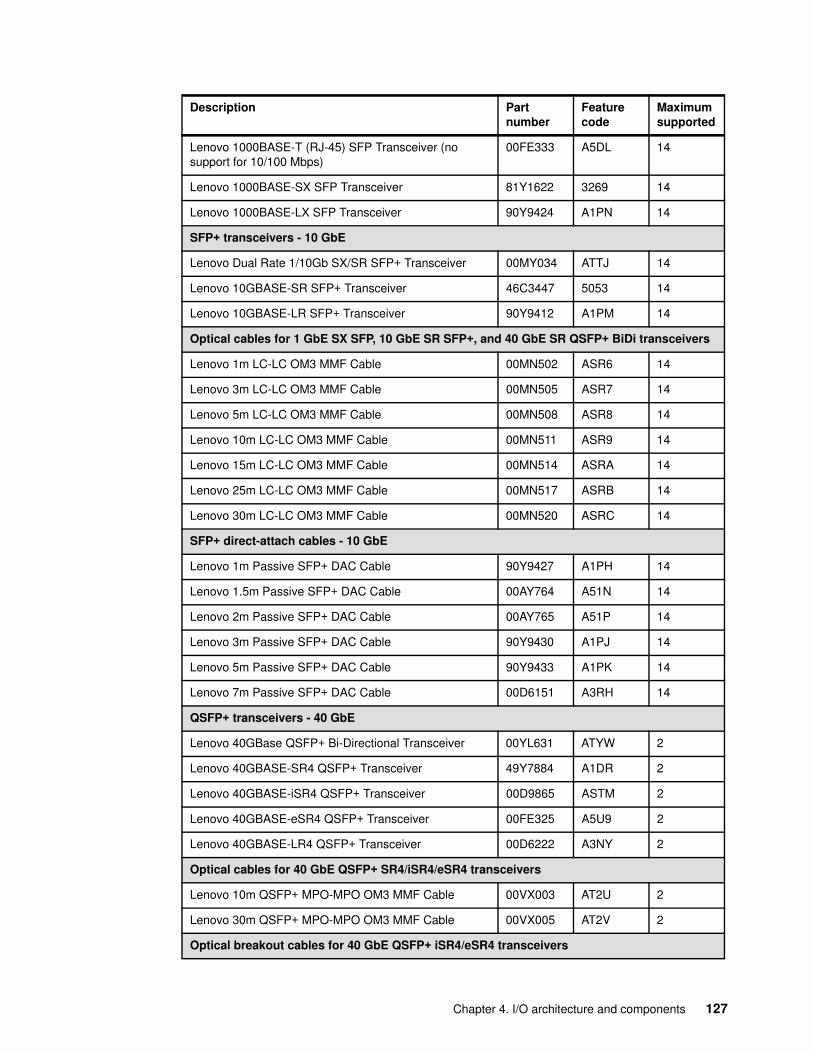
Lenovo 1000BASE-T (RJ-45) SFP Transceiver (no support for 10/100 Mbps)
00FE333 A5DL 14
Lenovo 1000BASE-SX SFP Transceiver 81Y1622 3269 14
Lenovo 1000BASE-LX SFP Transceiver 90Y9424 A1PN 14
SFP+ transceivers - 10 GbE
Lenovo Dual Rate 1/10Gb SX/SR SFP+ Transceiver 00MY034 ATTJ 14
Lenovo 10GBASE-SR SFP+ Transceiver 46C3447 5053 14
Lenovo 10GBASE-LR SFP+ Transceiver 90Y9412 A1PM 14
Optical cables for 1 GbE SX SFP, 10 GbE SR SFP+, and 40 GbE SR QSFP+ BiDi transceivers
Lenovo 1m LC-LC OM3 MMF Cable 00MN502 ASR6 14
Lenovo 3m LC-LC OM3 MMF Cable 00MN505 ASR7 14
Lenovo 5m LC-LC OM3 MMF Cable 00MN508 ASR8 14
Lenovo 10m LC-LC OM3 MMF Cable 00MN511 ASR9 14
Lenovo 15m LC-LC OM3 MMF Cable 00MN514 ASRA 14
Lenovo 25m LC-LC OM3 MMF Cable 00MN517 ASRB 14
Lenovo 30m LC-LC OM3 MMF Cable 00MN520 ASRC 14
SFP+ direct-attach cables - 10 GbE
Lenovo 1m Passive SFP+ DAC Cable 90Y9427 A1PH 14
Lenovo 1.5m Passive SFP+ DAC Cable 00AY764 A51N 14
Lenovo 2m Passive SFP+ DAC Cable 00AY765 A51P 14
Lenovo 3m Passive SFP+ DAC Cable 90Y9430 A1PJ 14
Lenovo 5m Passive SFP+ DAC Cable 90Y9433 A1PK 14
Lenovo 7m Passive SFP+ DAC Cable 00D6151 A3RH 14
QSFP+ transceivers - 40 GbE
Lenovo 40GBase QSFP+ Bi-Directional Transceiver 00YL631 ATYW 2
Lenovo 40GBASE-SR4 QSFP+ Transceiver 49Y7884 A1DR 2
Lenovo 40GBASE-iSR4 QSFP+ Transceiver 00D9865 ASTM 2
Lenovo 40GBASE-eSR4 QSFP+ Transceiver 00FE325 A5U9 2
Lenovo 40GBASE-LR4 QSFP+ Transceiver 00D6222 A3NY 2
Optical cables for 40 GbE QSFP+ SR4/iSR4/eSR4 transceivers
Lenovo 10m QSFP+ MPO-MPO OM3 MMF Cable 00VX003 AT2U 2
Lenovo 30m QSFP+ MPO-MPO OM3 MMF Cable 00VX005 AT2V 2
Optical breakout cables for 40 GbE QSFP+ iSR4/eSR4 transceivers
Description Part number
Feature code
Maximum supported
Chapter 4. I/O architecture and components 127
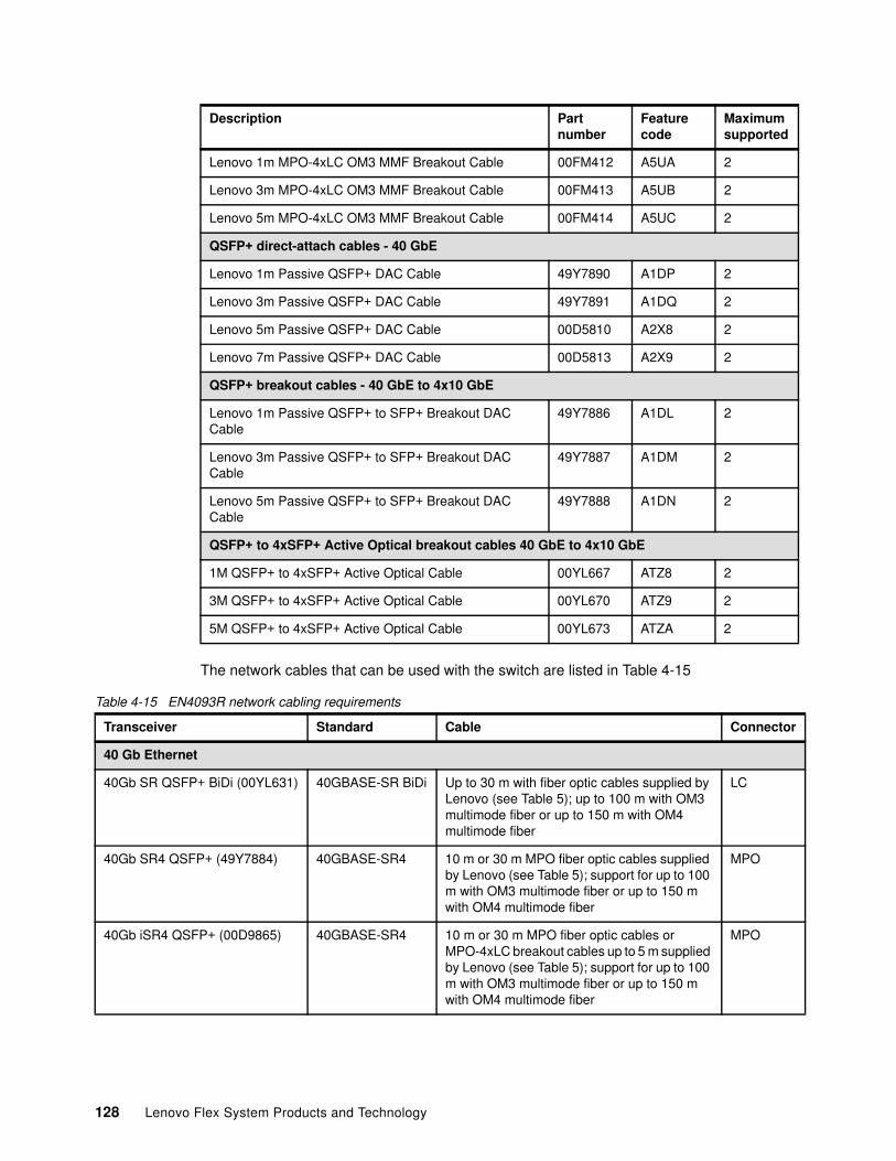
The network cables that can be used with the switch are listed in Table 4-15
Table 4-15 EN4093R network cabling requirements
Lenovo 1m MPO-4xLC OM3 MMF Breakout Cable 00FM412 A5UA 2
Lenovo 3m MPO-4xLC OM3 MMF Breakout Cable 00FM413 A5UB 2
Lenovo 5m MPO-4xLC OM3 MMF Breakout Cable 00FM414 A5UC 2
QSFP+ direct-attach cables - 40 GbE
Lenovo 1m Passive QSFP+ DAC Cable 49Y7890 A1DP 2
Lenovo 3m Passive QSFP+ DAC Cable 49Y7891 A1DQ 2
Lenovo 5m Passive QSFP+ DAC Cable 00D5810 A2X8 2
Lenovo 7m Passive QSFP+ DAC Cable 00D5813 A2X9 2
QSFP+ breakout cables - 40 GbE to 4x10 GbE
Lenovo 1m Passive QSFP+ to SFP+ Breakout DAC Cable
49Y7886 A1DL 2
Lenovo 3m Passive QSFP+ to SFP+ Breakout DAC Cable
49Y7887 A1DM 2
Lenovo 5m Passive QSFP+ to SFP+ Breakout DAC Cable
49Y7888 A1DN 2
QSFP+ to 4xSFP+ Active Optical breakout cables 40 GbE to 4x10 GbE
1M QSFP+ to 4xSFP+ Active Optical Cable 00YL667 ATZ8 2
3M QSFP+ to 4xSFP+ Active Optical Cable 00YL670 ATZ9 2
5M QSFP+ to 4xSFP+ Active Optical Cable 00YL673 ATZA 2
Description Part number
Feature code
Maximum supported
Transceiver Standard Cable Connector
40 Gb Ethernet
40Gb SR QSFP+ BiDi (00YL631) 40GBASE-SR BiDi Up to 30 m with fiber optic cables supplied by Lenovo (see Table 5); up to 100 m with OM3 multimode fiber or up to 150 m with OM4 multimode fiber
LC
40Gb SR4 QSFP+ (49Y7884) 40GBASE-SR4 10 m or 30 m MPO fiber optic cables supplied by Lenovo (see Table 5); support for up to 100 m with OM3 multimode fiber or up to 150 m with OM4 multimode fiber
MPO
40Gb iSR4 QSFP+ (00D9865) 40GBASE-SR4 10 m or 30 m MPO fiber optic cables or MPO-4xLC breakout cables up to 5 m supplied by Lenovo (see Table 5); support for up to 100 m with OM3 multimode fiber or up to 150 m with OM4 multimode fiber
MPO
128 Lenovo Flex System Products and Technology
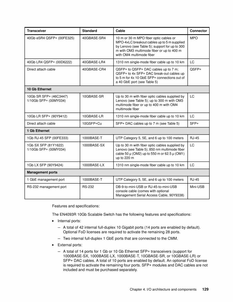
Features and specifications:
The EN4093R 10Gb Scalable Switch has the following features and specifications:
� Internal ports:
– A total of 42 internal full-duplex 10 Gigabit ports (14 ports are enabled by default). Optional FoD licenses are required to activate the remaining 28 ports.
– Two internal full-duplex 1 GbE ports that are connected to the CMM.
� External ports:
– A total of 14 ports for 1 Gb or 10 Gb Ethernet SFP+ transceivers (support for 1000BASE-SX, 1000BASE-LX, 1000BASE-T, 10GBASE-SR, or 10GBASE-LR) or SFP+ DAC cables. A total of 10 ports are enabled by default. An optional FoD license is required to activate the remaining four ports. SFP+ modules and DAC cables are not included and must be purchased separately.
40Gb eSR4 QSFP+ (00FE325) 40GBASE-SR4 10 m or 30 m MPO fiber optic cables or MPO-4xLC breakout cables up to 5 m supplied by Lenovo (see Table 5); support for up to 300 m with OM3 multimode fiber or up to 400 m with OM4 multimode fiber
MPO
40Gb LR4 QSFP+ (00D6222) 40GBASE-LR4 1310 nm single-mode fiber cable up to 10 km LC
Direct attach cable 40GBASE-CR4 QSFP+ to QSFP+ DAC cables up to 7 m; QSFP+ to 4x SFP+ DAC break-out cables up to 5 m for 4x 10 GbE SFP+ connections out of a 40 GbE port (see Table 5)
QSFP+
10 Gb Ethernet
10Gb SR SFP+ (46C3447)1/10Gb SFP+ (00MY034)
10GBASE-SR Up to 30 m with fiber optic cables supplied by Lenovo (see Table 5); up to 300 m with OM3 multimode fiber or up to 400 m with OM4 multimode fiber
LC
10Gb LR SFP+ (90Y9412) 10GBASE-LR 1310 nm single-mode fiber cable up to 10 km LC
Direct attach cable 10GSFP+Cu SFP+ DAC cables up to 7 m (see Table 5) SFP+
1 Gb Ethernet
1Gb RJ-45 SFP (00FE333) 1000BASE-T UTP Category 5, 5E, and 6 up to 100 meters RJ-45
1Gb SX SFP (81Y1622)1/10Gb SFP+ (00MY034)
1000BASE-SX Up to 30 m with fiber optic cables supplied by Lenovo (see Table 5); 850 nm multimode fiber cable 50 μ (OM2) up to 550 m or 62.5 μ (OM1) up to 220 m
LC
1Gb LX SFP (90Y9424) 1000BASE-LX 1310 nm single-mode fiber cable up to 10 km LC
Management ports
1 GbE management port 1000BASE-T UTP Category 5, 5E, and 6 up to 100 meters RJ-45
RS-232 management port RS-232 DB-9-to-mini-USB or RJ-45-to-mini-USB console cable (comes with optional Management Serial Access Cable, 90Y9338)
Mini-USB
Transceiver Standard Cable Connector
Chapter 4. I/O architecture and components 129
– Two ports for 40 Gb Ethernet QSFP+ transceivers or QSFP+ DACs (ports are disabled by default; an optional FoD license is required to activate them). QSFP+ modules and DAC cables are not included and must be purchased separately.
– One RS-232 serial port (mini-USB connector) that provides another means to configure the switch module.
� Scalability and performance:
– 40 Gb Ethernet ports for extreme uplink bandwidth and performance.
– Fixed-speed external 10 Gb Ethernet ports to use the 10 Gb core infrastructure.
– Autosensing 10/1000/1000 external Gigabit Ethernet ports for bandwidth optimization.
– Non-blocking architecture with wire-speed forwarding of traffic and aggregated throughput of 1.28 Tbps.
– MAC address learning: Automatic update; support for up to 128,000 MAC addresses.
– Up to 128 IP interfaces per switch.
– Static and LACP (IEEE 802.3ad) link aggregation: Up to 220 Gb of total uplink bandwidth per switch, up to 64 trunk groups, and up to 16 ports per group.
– Support for jumbo frames (up to 9,216 bytes).
– Broadcast/multicast storm control.
– IGMP snooping to limit flooding of IP multicast traffic.
– IGMP filtering to control multicast traffic for hosts that participate in multicast groups.
– Configurable traffic distribution schemes over trunk links that are based on source/destination IP or MAC addresses, or both.
– Fast port forwarding and fast uplink convergence for rapid STP convergence.
� Availability and redundancy:
– VRRP for Layer 3 router redundancy.
– IEEE 802.1D STP for providing L2 redundancy.
– IEEE 802.1s MSTP for topology optimization, up to 32 STP instances are supported by single switch.
– IEEE 802.1w RSTP provides rapid STP convergence for critical delay-sensitive traffic like voice or video.
– RPVST enhancements.
– Layer 2 Trunk Failover to support active/standby configurations of network adapter that team on compute nodes.
– Hot Links provides basic link redundancy with fast recovery for network topologies that require Spanning Tree to be turned off.
� VLAN support:
– Up to 1024 VLANs supported per switch, with VLAN numbers that range 1 - 4095 (4095 is used for the management module’s connection only).
– 802.1Q VLAN tagging support on all ports.
– Private VLANs.
� Security:
– VLAN-based, MAC-based, and IP-based ACLs– 802.1x port-based authentication– Multiple user IDs and passwords
130 Lenovo Flex System Products and Technology
– User access control– Radius, TACACS+, and LDAP authentication and authorization
� Quality of service (QoS):
– Support for IEEE 802.1p, IP ToS/DSCP, and ACL-based (MAC/IP source, destination addresses, and VLANs) traffic classification and processing.
– Traffic shaping and remarking based on defined policies.
– Eight WRR priority queues per port for processing qualified traffic.
� IP v4 Layer 3 functions:
– Host management
– IP forwarding
– IP filtering with ACLs, up to 896 ACLs supported
– VRRP for router redundancy
– Support for up to 128 static routes
– Routing protocol support (RIP v1, RIP v2, OSPF v2, and BGP-4), up to 2048 entries in a routing table
– Support for DHCP Relay
– Support for IGMP snooping and IGMP relay
– Support for Protocol Independent Multicast (PIM) in Sparse Mode (PIM-SM) and Dense Mode (PIM-DM)
– 802.1Qbg support
� IP v6 Layer 3 functions:
– IPv6 host management (except default switch management IP address)– IPv6 forwarding– Up to 128 static routes– Support for OSPF v3 routing protocol– IPv6 filtering with ACLs
� Virtualization:
– Virtual Fabric with vNIC– 802.1Qbg EVB – VMready
� Converged Enhanced Ethernet:
– PFC (IEEE 802.1Qbb) extends 802.3x standard flow control to allow the switch to pause traffic. This function is based on the 802.1p priority value in each packet’s VLAN tag.
– ETS (IEEE 802.1Qaz) provides a method for allocating link bandwidth that is based on the 802.1p priority value in each packet’s VLAN tag.
– DCBX (IEEE 802.1AB) allows neighboring network devices to exchange information about their capabilities.
� Manageability:
– SNMP V1, V2, and V3
– HTTP browser GUI
– Telnet interface for CLI
– Secure Shell (SSH)
Chapter 4. I/O architecture and components 131
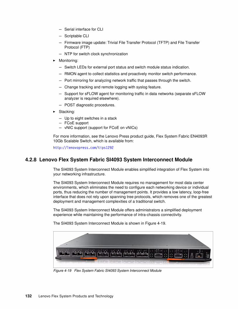
– Serial interface for CLI
– Scriptable CLI
– Firmware image update: Trivial File Transfer Protocol (TFTP) and File Transfer Protocol (FTP)
– NTP for switch clock synchronization
� Monitoring:
– Switch LEDs for external port status and switch module status indication.
– RMON agent to collect statistics and proactively monitor switch performance.
– Port mirroring for analyzing network traffic that passes through the switch.
– Change tracking and remote logging with syslog feature.
– Support for sFLOW agent for monitoring traffic in data networks (separate sFLOW analyzer is required elsewhere).
– POST diagnostic procedures.
� Stacking:
– Up to eight switches in a stack– FCoE support– vNIC support (support for FCoE on vNICs)
For more information, see the Lenovo Press product guide, Flex System Fabric EN4093R 10Gb Scalable Switch, which is available from:
http://lenovopress.com/tips1292
4.2.8 Lenovo Flex System Fabric SI4093 System Interconnect Module
The SI4093 System Interconnect Module enables simplified integration of Flex System into your networking infrastructure.
The SI4093 System Interconnect Module requires no management for most data center environments, which eliminates the need to configure each networking device or individual ports, thus reducing the number of management points. It provides a low latency, loop-free interface that does not rely upon spanning tree protocols, which removes one of the greatest deployment and management complexities of a traditional switch.
The SI4093 System Interconnect Module offers administrators a simplified deployment experience while maintaining the performance of intra-chassis connectivity.
The SI4093 System Interconnect Module is shown in Figure 4-19.
Figure 4-19 Flex System Fabric SI4093 System Interconnect Module
132 Lenovo Flex System Products and Technology
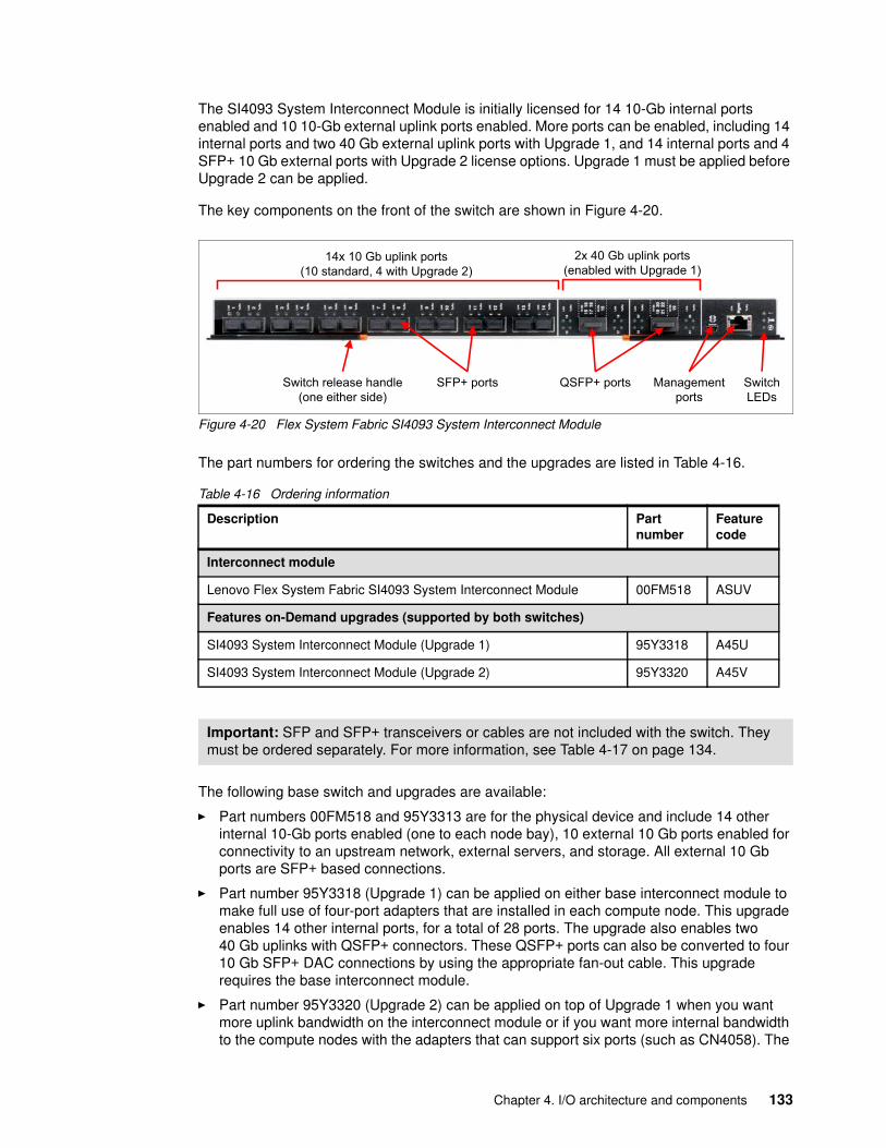
The SI4093 System Interconnect Module is initially licensed for 14 10-Gb internal ports enabled and 10 10-Gb external uplink ports enabled. More ports can be enabled, including 14 internal ports and two 40 Gb external uplink ports with Upgrade 1, and 14 internal ports and 4 SFP+ 10 Gb external ports with Upgrade 2 license options. Upgrade 1 must be applied before Upgrade 2 can be applied.
The key components on the front of the switch are shown in Figure 4-20.
Figure 4-20 Flex System Fabric SI4093 System Interconnect Module
The part numbers for ordering the switches and the upgrades are listed in Table 4-16.
Table 4-16 Ordering information
The following base switch and upgrades are available:
� Part numbers 00FM518 and 95Y3313 are for the physical device and include 14 other internal 10-Gb ports enabled (one to each node bay), 10 external 10 Gb ports enabled for connectivity to an upstream network, external servers, and storage. All external 10 Gb ports are SFP+ based connections.
� Part number 95Y3318 (Upgrade 1) can be applied on either base interconnect module to make full use of four-port adapters that are installed in each compute node. This upgrade enables 14 other internal ports, for a total of 28 ports. The upgrade also enables two 40 Gb uplinks with QSFP+ connectors. These QSFP+ ports can also be converted to four 10 Gb SFP+ DAC connections by using the appropriate fan-out cable. This upgrade requires the base interconnect module.
� Part number 95Y3320 (Upgrade 2) can be applied on top of Upgrade 1 when you want more uplink bandwidth on the interconnect module or if you want more internal bandwidth to the compute nodes with the adapters that can support six ports (such as CN4058). The
Description Partnumber
Featurecode
Interconnect module
Lenovo Flex System Fabric SI4093 System Interconnect Module 00FM518 ASUV
Features on-Demand upgrades (supported by both switches)
SI4093 System Interconnect Module (Upgrade 1) 95Y3318 A45U
SI4093 System Interconnect Module (Upgrade 2) 95Y3320 A45V
Important: SFP and SFP+ transceivers or cables are not included with the switch. They must be ordered separately. For more information, see Table 4-17 on page 134.
14x 10 Gb uplink ports (10 standard, 4 with Upgrade 2)
2x 40 Gb uplink ports (enabled with Upgrade 1)
SFP+ portsSwitch release handle (one either side)
QSFP+ ports Managementports
SwitchLEDs
Chapter 4. I/O architecture and components 133
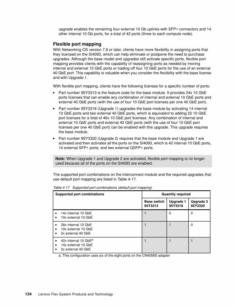
upgrade enables the remaining four external 10 Gb uplinks with SFP+ connectors and 14 other internal 10 Gb ports, for a total of 42 ports (three to each compute node).
Flexible port mappingWith Networking OS version 7.8 or later, clients have more flexibility in assigning ports that they licensed on the SI4093, which can help eliminate or postpone the need to purchase upgrades. Although the base model and upgrades still activate specific ports, flexible port mapping provides clients with the capability of reassigning ports as needed by moving internal and external 10 GbE ports or trading off four 10 GbE ports for the use of an external 40 GbE port. This capability is valuable when you consider the flexibility with the base license and with Upgrade 1.
With flexible port mapping, clients have the following licenses for a specific number of ports:
� Part number 95Y3313 is the feature code for the base module. It provides 24x 10 GbE ports licenses that can enable any combination of internal and external 10 GbE ports and external 40 GbE ports (with the use of four 10 GbE port licenses per one 40 GbE port).
� Part number 95Y3318 (Upgrade 1) upgrades the base module by activating 14 internal 10 GbE ports and two external 40 GbE ports, which is equivalent to adding 22 10 GbE port licenses for a total of 46x 10 GbE port licenses. Any combination of internal and external 10 GbE ports and external 40 GbE ports (with the use of four 10 GbE port licenses per one 40 GbE port) can be enabled with this upgrade. This upgrade requires the base module.
� Part number 95Y3320 (Upgrade 2) requires that the base module and Upgrade 1 are activated and then activates all the ports on the SI4093, which is 42 internal 10 GbE ports, 14 external SFP+ ports, and two external QSFP+ ports.
The supported port combinations on the interconnect module and the required upgrades that use default port mapping are listed in Table 4-17.
Table 4-17 Supported port combinations (default port mapping)
Note: When Upgrade 1 and Upgrade 2 are activated, flexible port mapping is no longer used because all of the ports on the SI4093 are enabled.
Supported port combinations Quantity required
Base switch95Y3313
Upgrade 195Y3318
Upgrade 295Y3320
� 14x internal 10 GbE� 10x external 10 GbE
1 0 0
� 28x internal 10 GbE� 10x external 10 GbE� 2x external 40 GbE
1 1 0
� 42x internal 10 GbEa
� 14x external 10 GbE� 2x external 40 GbE
a. This configuration uses six of the eight ports on the CN4058S adapter
1 1 1
134 Lenovo Flex System Products and Technology
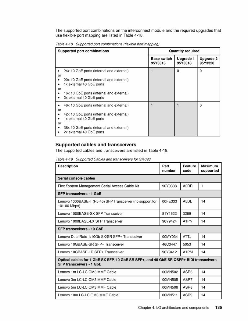
The supported port combinations on the interconnect module and the required upgrades that use flexible port mapping are listed in Table 4-18.
Table 4-18 Supported port combinations (flexible port mapping)
Supported cables and transceiversThe supported cables and transceivers are listed in Table 4-19.
Table 4-19 Supported Cables and transceivers for SI4093
Supported port combinations Quantity required
Base switch95Y3313
Upgrade 195Y3318
Upgrade 295Y3320
� 24x 10 GbE ports (internal and external)or� 20x 10 GbE ports (internal and external)� 1x external 40 GbE portsor� 16x 10 GbE ports (internal and external)� 2x external 40 GbE ports
1 0 0
� 46x 10 GbE ports (internal and external)or� 42x 10 GbE ports (internal and external)� 1x external 40 GbE portsor� 38x 10 GbE ports (internal and external)� 2x external 40 GbE ports
1 1 0
Description Partnumber
Featurecode
Maximumsupported
Serial console cables
Flex System Management Serial Access Cable Kit 90Y9338 A2RR 1
SFP transceivers - 1 GbE
Lenovo 1000BASE-T (RJ-45) SFP Transceiver (no support for 10/100 Mbps)
00FE333 A5DL 14
Lenovo 1000BASE-SX SFP Transceiver 81Y1622 3269 14
Lenovo 1000BASE-LX SFP Transceiver 90Y9424 A1PN 14
SFP transceivers - 10 GbE
Lenovo Dual Rate 1/10Gb SX/SR SFP+ Transceiver 00MY034 ATTJ 14
Lenovo 10GBASE-SR SFP+ Transceiver 46C3447 5053 14
Lenovo 10GBASE-LR SFP+ Transceiver 90Y9412 A1PM 14
Optical cables for 1 GbE SX SFP, 10 GbE SR SFP+, and 40 GbE SR QSFP+ BiDi transceivers SFP transceivers - 1 GbE
Lenovo 1m LC-LC OM3 MMF Cable 00MN502 ASR6 14
Lenovo 3m LC-LC OM3 MMF Cable 00MN505 ASR7 14
Lenovo 5m LC-LC OM3 MMF Cable 00MN508 ASR8 14
Lenovo 10m LC-LC OM3 MMF Cable 00MN511 ASR9 14
Chapter 4. I/O architecture and components 135
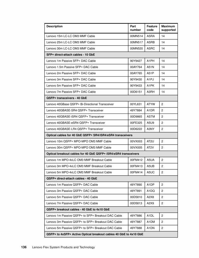
Lenovo 15m LC-LC OM3 MMF Cable 00MN514 ASRA 14
Lenovo 25m LC-LC OM3 MMF Cable 00MN517 ASRB 14
Lenovo 30m LC-LC OM3 MMF Cable 00MN520 ASRC 14
SFP+ direct-attach cables - 10 GbE
Lenovo 1m Passive SFP+ DAC Cable 90Y9427 A1PH 14
Lenovo 1.5m Passive SFP+ DAC Cable 00AY764 A51N 14
Lenovo 2m Passive SFP+ DAC Cable 00AY765 A51P 14
Lenovo 3m Passive SFP+ DAC Cable 90Y9430 A1PJ 14
Lenovo 5m Passive SFP+ DAC Cable 90Y9433 A1PK 14
Lenovo 7m Passive SFP+ DAC Cable 00D6151 A3RH 14
QSFP+ transceivers - 40 GbE
Lenovo 40GBase QSFP+ Bi-Directional Transceiver 00YL631 ATYW 2
Lenovo 40GBASE-SR4 QSFP+ Transceiver 49Y7884 A1DR 2
Lenovo 40GBASE-iSR4 QSFP+ Transceiver 00D9865 ASTM 2
Lenovo 40GBASE-eSR4 QSFP+ Transceiver 00FE325 A5U9 2
Lenovo 40GBASE-LR4 QSFP+ Transceiver 00D6222 A3NY 2
Optical cables for 40 GbE QSFP+ SR4/iSR4/eSR4 transceivers
Lenovo 10m QSFP+ MPO-MPO OM3 MMF Cable 00VX003 AT2U 2
Lenovo 30m QSFP+ MPO-MPO OM3 MMF Cable 00VX005 AT2V 2
Optical breakout cables for 40 GbE QSFP+ iSR4/eSR4 transceivers
Lenovo 1m MPO-4xLC OM3 MMF Breakout Cable 00FM412 A5UA 2
Lenovo 3m MPO-4xLC OM3 MMF Breakout Cable 00FM413 A5UB 2
Lenovo 5m MPO-4xLC OM3 MMF Breakout Cable 00FM414 A5UC 2
QSFP+ direct-attach cables - 40 GbE
Lenovo 1m Passive QSFP+ DAC Cable 49Y7890 A1DP 2
Lenovo 3m Passive QSFP+ DAC Cable 49Y7891 A1DQ 2
Lenovo 5m Passive QSFP+ DAC Cable 00D5810 A2X8 2
Lenovo 7m Passive QSFP+ DAC Cable 00D5813 A2X9 2
QSFP+ breakout cables - 40 GbE to 4x10 GbE
Lenovo 1m Passive QSFP+ to SFP+ Breakout DAC Cable 49Y7886 A1DL 2
Lenovo 3m Passive QSFP+ to SFP+ Breakout DAC Cable 49Y7887 A1DM 2
Lenovo 5m Passive QSFP+ to SFP+ Breakout DAC Cable 49Y7888 A1DN 2
QSFP+ to 4xSFP+ Active Optical breakout cables 40 GbE to 4x10 GbE
Description Partnumber
Featurecode
Maximumsupported
136 Lenovo Flex System Products and Technology
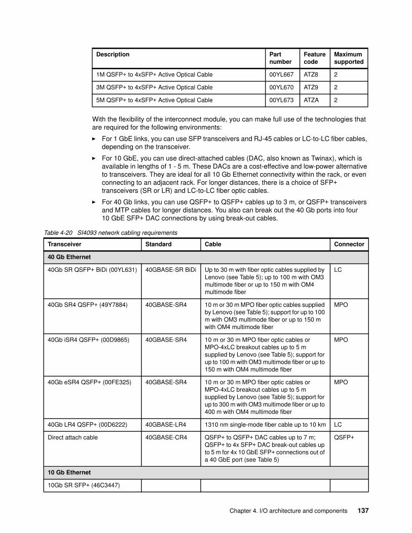
With the flexibility of the interconnect module, you can make full use of the technologies that are required for the following environments:
� For 1 GbE links, you can use SFP transceivers and RJ-45 cables or LC-to-LC fiber cables, depending on the transceiver.
� For 10 GbE, you can use direct-attached cables (DAC, also known as Twinax), which is available in lengths of 1 - 5 m. These DACs are a cost-effective and low-power alternative to transceivers. They are ideal for all 10 Gb Ethernet connectivity within the rack, or even connecting to an adjacent rack. For longer distances, there is a choice of SFP+ transceivers (SR or LR) and LC-to-LC fiber optic cables.
� For 40 Gb links, you can use QSFP+ to QSFP+ cables up to 3 m, or QSFP+ transceivers and MTP cables for longer distances. You also can break out the 40 Gb ports into four 10 GbE SFP+ DAC connections by using break-out cables.
Table 4-20 SI4093 network cabling requirements
1M QSFP+ to 4xSFP+ Active Optical Cable 00YL667 ATZ8 2
3M QSFP+ to 4xSFP+ Active Optical Cable 00YL670 ATZ9 2
5M QSFP+ to 4xSFP+ Active Optical Cable 00YL673 ATZA 2
Description Partnumber
Featurecode
Maximumsupported
Transceiver Standard Cable Connector
40 Gb Ethernet
40Gb SR QSFP+ BiDi (00YL631) 40GBASE-SR BiDi Up to 30 m with fiber optic cables supplied by Lenovo (see Table 5); up to 100 m with OM3 multimode fiber or up to 150 m with OM4 multimode fiber
LC
40Gb SR4 QSFP+ (49Y7884) 40GBASE-SR4 10 m or 30 m MPO fiber optic cables supplied by Lenovo (see Table 5); support for up to 100 m with OM3 multimode fiber or up to 150 m with OM4 multimode fiber
MPO
40Gb iSR4 QSFP+ (00D9865) 40GBASE-SR4 10 m or 30 m MPO fiber optic cables or MPO-4xLC breakout cables up to 5 m supplied by Lenovo (see Table 5); support for up to 100 m with OM3 multimode fiber or up to 150 m with OM4 multimode fiber
MPO
40Gb eSR4 QSFP+ (00FE325) 40GBASE-SR4 10 m or 30 m MPO fiber optic cables or MPO-4xLC breakout cables up to 5 m supplied by Lenovo (see Table 5); support for up to 300 m with OM3 multimode fiber or up to 400 m with OM4 multimode fiber
MPO
40Gb LR4 QSFP+ (00D6222) 40GBASE-LR4 1310 nm single-mode fiber cable up to 10 km LC
Direct attach cable 40GBASE-CR4 QSFP+ to QSFP+ DAC cables up to 7 m; QSFP+ to 4x SFP+ DAC break-out cables up to 5 m for 4x 10 GbE SFP+ connections out of a 40 GbE port (see Table 5)
QSFP+
10 Gb Ethernet
10Gb SR SFP+ (46C3447)
Chapter 4. I/O architecture and components 137
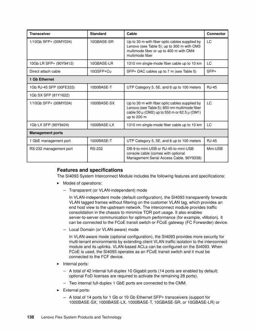
Features and specificationsThe SI4093 System Interconnect Module includes the following features and specifications:
� Modes of operations:
– Transparent (or VLAN-independent) mode
In VLAN-independent mode (default configuration), the SI4093 transparently forwards VLAN tagged frames without filtering on the customer VLAN tag, which provides an end host view to the upstream network. The interconnect module provides traffic consolidation in the chassis to minimize TOR port usage. It also enables server-to-server communication for optimum performance (for example, vMotion). It can be connected to the FCoE transit switch or FCoE gateway (FC Forwarder) device.
– Local Domain (or VLAN-aware) mode
In VLAN-aware mode (optional configuration), the SI4093 provides more security for multi-tenant environments by extending client VLAN traffic isolation to the interconnect module and its uplinks. VLAN-based ACLs can be configured on the SI4093. When FCoE is used, the SI4093 operates as an FCoE transit switch and it must be connected to the FCF device.
� Internal ports:
– A total of 42 internal full-duplex 10 Gigabit ports (14 ports are enabled by default; optional FoD licenses are required to activate the remaining 28 ports).
– Two internal full-duplex 1 GbE ports are connected to the CMM.
� External ports:
– A total of 14 ports for 1 Gb or 10 Gb Ethernet SFP+ transceivers (support for 1000BASE-SX, 1000BASE-LX, 1000BASE-T, 10GBASE-SR, or 10GBASE-LR) or
1/10Gb SFP+ (00MY034) 10GBASE-SR Up to 30 m with fiber optic cables supplied by Lenovo (see Table 5); up to 300 m with OM3 multimode fiber or up to 400 m with OM4 multimode fiber
LC
10Gb LR SFP+ (90Y9412) 10GBASE-LR 1310 nm single-mode fiber cable up to 10 km LC
Direct attach cable 10GSFP+Cu SFP+ DAC cables up to 7 m (see Table 5) SFP+
1 Gb Ethernet
1Gb RJ-45 SFP (00FE333) 1000BASE-T UTP Category 5, 5E, and 6 up to 100 meters RJ-45
1Gb SX SFP (81Y1622)
1/10Gb SFP+ (00MY034) 1000BASE-SX Up to 30 m with fiber optic cables supplied by Lenovo (see Table 5); 850 nm multimode fiber cable 50 μ (OM2) up to 550 m or 62.5 μ (OM1) up to 220 m
LC
1Gb LX SFP (90Y9424) 1000BASE-LX 1310 nm single-mode fiber cable up to 10 km LC
Management ports
1 GbE management port 1000BASE-T UTP Category 5, 5E, and 6 up to 100 meters RJ-45
RS-232 management port RS-232 DB-9-to-mini-USB or RJ-45-to-mini-USB console cable (comes with optional Management Serial Access Cable, 90Y9338)
Mini-USB
Transceiver Standard Cable Connector
138 Lenovo Flex System Products and Technology
SFP+ copper DAC. A total of 10 ports are enabled by default. An optional FoD license is required to activate the remaining four ports. SFP+ modules and DACs are not included and must be purchased separately.
– Two ports for 40 Gb Ethernet QSFP+ transceivers or QSFP+ DACs. (Ports are disabled by default. An optional FoD license is required to activate them.) QSFP+ modules and DACs are not included and must be purchased separately.
– One RS-232 serial port (mini-USB connector) that provides another means to configure the switch module.
� Scalability and performance:
– 40 Gb Ethernet ports for extreme uplink bandwidth and performance.
– External 10 Gb Ethernet ports to use 10 Gb upstream infrastructure.
– Non-blocking architecture with wire-speed forwarding of traffic and aggregated throughput of 1.28 Tbps.
– MAC address learning: Automatic update; support for up to 128,000 MAC addresses.
– Static and LACP (IEEE 802.3ad) link aggregation, up to 220 Gb of total uplink bandwidth per interconnect module.
– Support for jumbo frames (up to 9,216 bytes).
� Availability and redundancy:
– Layer 2 Trunk Failover to support active/standby configurations of network adapter teaming on compute nodes.
– Built in link redundancy with loop prevention without a need for Spanning Tree protocol.
� VLAN support:
– Up to 32 VLANs supported per interconnect module SPAR partition, with VLAN numbers 1 - 4095 (4095 is used for management module’s connection only).
– 802.1Q VLAN tagging support on all ports.
� Security:
– VLAN-based ACLs (VLAN-aware mode).– Multiple user IDs and passwords.– User access control.– Radius, TACACS+, and LDAP authentication and authorization.
� Quality of service
Support for IEEE 802.1p traffic classification and processing.
� Virtualization:
– Switch Independent Virtual NIC (vNIC2)
Ethernet, iSCSI, or FCoE traffic is supported on vNICs
– SPAR:
• SPAR forms separate virtual switching contexts by segmenting the data plane of the switch. Data plane traffic is not shared between SPARs on the same switch.
• SPAR operates as a Layer 2 broadcast network. Hosts on the same VLAN that is attached to a SPAR can communicate with each other and with the upstream switch. Hosts on the same VLAN (but are attached to different SPARs) communicate through the upstream switch.
Chapter 4. I/O architecture and components 139
• SPAR is implemented as a dedicated VLAN with a set of internal server ports and a single uplink port or LAG. Multiple uplink ports or LAGs are not allowed in SPAR. A port can be a member of only one SPAR.
� Converged Enhanced Ethernet:
– PFC (IEEE 802.1Qbb) extends 802.3x standard flow control to allow the switch to pause traffic that is based on the 802.1p priority value in each packet’s VLAN tag.
– ETS (IEEE 802.1Qaz) provides a method for allocating link bandwidth that is based on the 802.1p priority value in each packet’s VLAN tag.
– DCBX (IEEE 802.1AB) allows neighboring network devices to exchange information about their capabilities.
� FCoE:
– FC-BB5 FCoE specification compliant.– FCoE transit switch operations.– FIP support.
� Manageability:
– IPv4 and IPv6 host management– SNMP V1, V2, and V3– IS-CLI through Telnet, SSH, and serial port– sFTP– SLP– Firmware image update (TFTP and FTP/sFTP)– NTP for clock synchronization– System Networking Switch Center (SNSC) support
� Monitoring:
– Switch LEDs for external port status and switch module status indication.– Change tracking and remote logging with syslog feature.– POST diagnostic tests.
Supported standardsThe switches support the following standards:
� IEEE 802.1AB Data Center Bridging Capability Exchange Protocol� IEEE 802.1p Class of Service (CoS) prioritization� IEEE 802.1Q Tagged VLAN (frame tagging on all ports when VLANs are enabled)� IEEE 802.1Qbb Priority-Based Flow Control� IEEE 802.1Qaz Enhanced Transmission Selection� IEEE 802.3 10BASE-T Ethernet� IEEE 802.3ab 1000BASE-T copper twisted-pair Gigabit Ethernet� IEEE 802.3ad Link Aggregation Control Protocol� IEEE 802.3ae 10GBASE-SR short range fiber optics 10 Gb Ethernet� IEEE 802.3ae 10GBASE-LR long range fiber optics 10 Gb Ethernet� IEEE 802.3ba 40GBASE-SR4 short range fiber optics 40 Gb Ethernet� IEEE 802.3ba 40GBASE-CR4 copper 40 Gb Ethernet� IEEE 802.3u 100BASE-TX Fast Ethernet� IEEE 802.3x Full-duplex Flow Control � IEEE 802.3z 1000BASE-SX short range fiber optics Gigabit Ethernet� IEEE 802.3z 1000BASE-LX long range fiber optics Gigabit Ethernet� SFF-8431 10GSFP+Cu SFP+ Direct Attach Cable
140 Lenovo Flex System Products and Technology
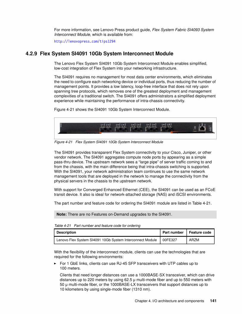
For more information, see Lenovo Press product guide, Flex System Fabric SI4093 System Interconnect Module, which is available from:
http://lenovopress.com/tips1294
4.2.9 Flex System SI4091 10Gb System Interconnect Module
The Lenovo Flex System SI4091 10Gb System Interconnect Module enables simplified, low-cost integration of Flex System into your networking infrastructure.
The SI4091 requires no management for most data center environments, which eliminates the need to configure each networking device or individual ports, thus reducing the number of management points. It provides a low latency, loop-free interface that does not rely upon spanning tree protocols, which removes one of the greatest deployment and management complexities of a traditional switch. The SI4091 offers administrators a simplified deployment experience while maintaining the performance of intra-chassis connectivity.
Figure 4-21 shows the SI4091 10Gb System Interconnect Module.
Figure 4-21 Flex System SI4091 10Gb System Interconnect Module
The SI4091 provides transparent Flex System connectivity to your Cisco, Juniper, or other vendor network. The SI4091 aggregates compute node ports by appearing as a simple pass-thru device. The upstream network sees a “large pipe” of server traffic coming to and from the chassis, with the main difference being that intra-chassis switching is supported. With the SI4091, your network administration team continues to use the same network management tools that are deployed in the network to manage the connectivity from the physical servers in the chassis to the upstream network.
With support for Converged Enhanced Ethernet (CEE), the SI4091 can be used as an FCoE transit device. It also is ideal for network-attached storage (NAS) and iSCSI environments.
The part number and feature code for ordering the SI4091 module are listed in Table 4-21.
Table 4-21 Part number and feature code for ordering
With the flexibility of the interconnect module, clients can use the technologies that are required for the following environments:
� For 1 GbE links, clients can use RJ-45 SFP transceivers with UTP cables up to 100 meters.
Clients that need longer distances can use a 1000BASE-SX transceiver, which can drive distances up to 220 meters by using 62.5 μ multi-mode fiber and up to 550 meters with 50 μ multi-mode fiber, or the 1000BASE-LX transceivers that support distances up to 10 kilometers by using single-mode fiber (1310 nm).
Note: There are no Features on-Demand upgrades to the SI4091.
Description Part number Feature code
Lenovo Flex System SI4091 10Gb System Interconnect Module 00FE327 ARZM
Chapter 4. I/O architecture and components 141
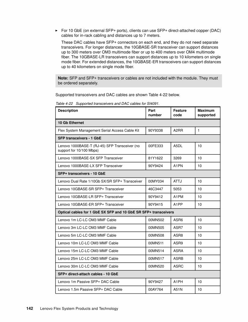
� For 10 GbE (on external SFP+ ports), clients can use SFP+ direct-attached copper (DAC) cables for in-rack cabling and distances up to 7 meters.
These DAC cables have SFP+ connectors on each end, and they do not need separate transceivers. For longer distances, the 10GBASE-SR transceiver can support distances up to 300 meters over OM3 multimode fiber or up to 400 meters over OM4 multimode fiber. The 10GBASE-LR transceivers can support distances up to 10 kilometers on single mode fiber. For extended distances, the 10GBASE-ER transceivers can support distances up to 40 kilometers on single mode fiber.
Supported transceivers and DAC cables are shown Table 4-22 below.
Table 4-22 Supported transceivers and DAC cables for SI4091.
Note: SFP and SFP+ transceivers or cables are not included with the module. They must be ordered separately.
Description Part number
Feature code
Maximum supported
10 Gb Ethernet
Flex System Management Serial Access Cable Kit 90Y9338 A2RR 1
SFP transceivers - 1 GbE
Lenovo 1000BASE-T (RJ-45) SFP Transceiver (no support for 10/100 Mbps)
00FE333 A5DL 10
Lenovo 1000BASE-SX SFP Transceiver 81Y1622 3269 10
Lenovo 1000BASE-LX SFP Transceiver 90Y9424 A1PN 10
SFP+ transceivers - 10 GbE
Lenovo Dual Rate 1/10Gb SX/SR SFP+ Transceiver 00MY034 ATTJ 10
Lenovo 10GBASE-SR SFP+ Transceiver 46C3447 5053 10
Lenovo 10GBASE-LR SFP+ Transceiver 90Y9412 A1PM 10
Lenovo 10GBASE-ER SFP+ Transceiver 90Y9415 A1PP 10
Optical cables for 1 GbE SX SFP and 10 GbE SR SFP+ transceivers
Lenovo 1m LC-LC OM3 MMF Cable 00MN502 ASR6 10
Lenovo 3m LC-LC OM3 MMF Cable 00MN505 ASR7 10
Lenovo 5m LC-LC OM3 MMF Cable 00MN508 ASR8 10
Lenovo 10m LC-LC OM3 MMF Cable 00MN511 ASR9 10
Lenovo 15m LC-LC OM3 MMF Cable 00MN514 ASRA 10
Lenovo 25m LC-LC OM3 MMF Cable 00MN517 ASRB 10
Lenovo 30m LC-LC OM3 MMF Cable 00MN520 ASRC 10
SFP+ direct-attach cables - 10 GbE
Lenovo 1m Passive SFP+ DAC Cable 90Y9427 A1PH 10
Lenovo 1.5m Passive SFP+ DAC Cable 00AY764 A51N 10
142 Lenovo Flex System Products and Technology
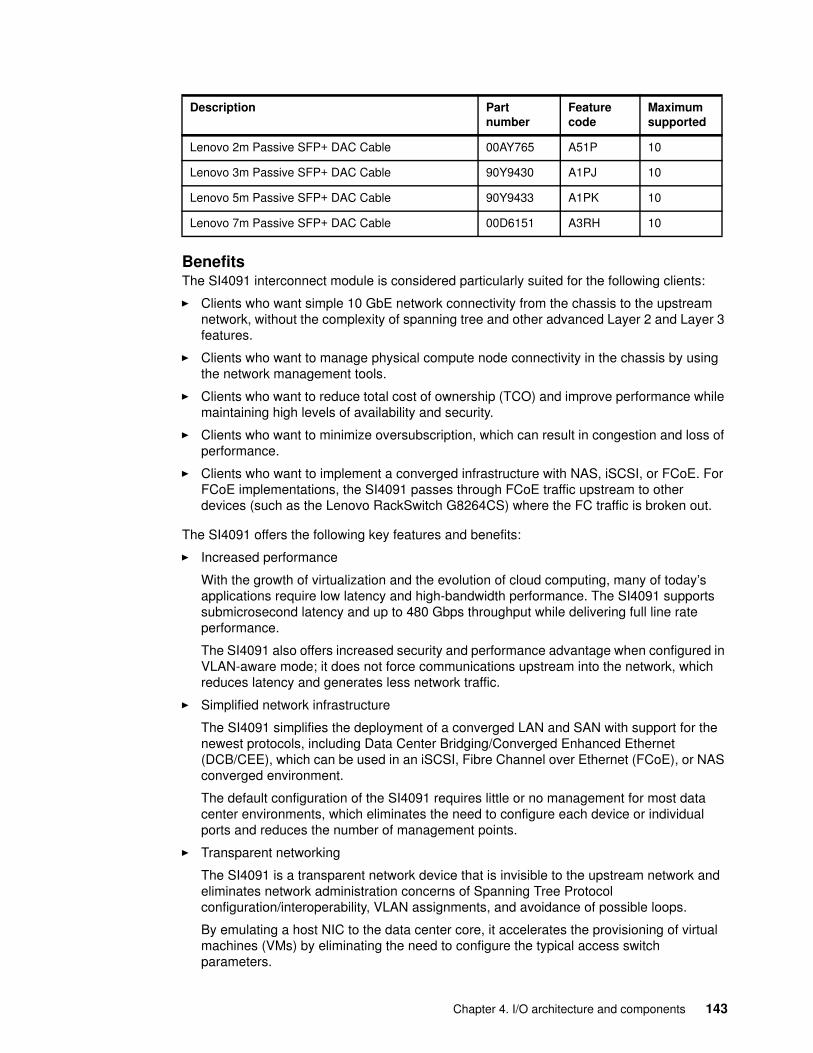
BenefitsThe SI4091 interconnect module is considered particularly suited for the following clients:
� Clients who want simple 10 GbE network connectivity from the chassis to the upstream network, without the complexity of spanning tree and other advanced Layer 2 and Layer 3 features.
� Clients who want to manage physical compute node connectivity in the chassis by using the network management tools.
� Clients who want to reduce total cost of ownership (TCO) and improve performance while maintaining high levels of availability and security.
� Clients who want to minimize oversubscription, which can result in congestion and loss of performance.
� Clients who want to implement a converged infrastructure with NAS, iSCSI, or FCoE. For FCoE implementations, the SI4091 passes through FCoE traffic upstream to other devices (such as the Lenovo RackSwitch G8264CS) where the FC traffic is broken out.
The SI4091 offers the following key features and benefits:
� Increased performance
With the growth of virtualization and the evolution of cloud computing, many of today’s applications require low latency and high-bandwidth performance. The SI4091 supports submicrosecond latency and up to 480 Gbps throughput while delivering full line rate performance.
The SI4091 also offers increased security and performance advantage when configured in VLAN-aware mode; it does not force communications upstream into the network, which reduces latency and generates less network traffic.
� Simplified network infrastructure
The SI4091 simplifies the deployment of a converged LAN and SAN with support for the newest protocols, including Data Center Bridging/Converged Enhanced Ethernet (DCB/CEE), which can be used in an iSCSI, Fibre Channel over Ethernet (FCoE), or NAS converged environment.
The default configuration of the SI4091 requires little or no management for most data center environments, which eliminates the need to configure each device or individual ports and reduces the number of management points.
� Transparent networking
The SI4091 is a transparent network device that is invisible to the upstream network and eliminates network administration concerns of Spanning Tree Protocol configuration/interoperability, VLAN assignments, and avoidance of possible loops.
By emulating a host NIC to the data center core, it accelerates the provisioning of virtual machines (VMs) by eliminating the need to configure the typical access switch parameters.
Lenovo 2m Passive SFP+ DAC Cable 00AY765 A51P 10
Lenovo 3m Passive SFP+ DAC Cable 90Y9430 A1PJ 10
Lenovo 5m Passive SFP+ DAC Cable 90Y9433 A1PK 10
Lenovo 7m Passive SFP+ DAC Cable 00D6151 A3RH 10
Description Part number
Feature code
Maximum supported
Chapter 4. I/O architecture and components 143
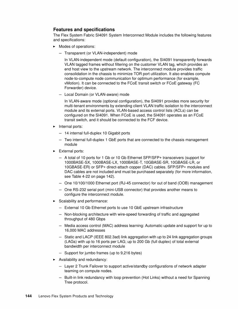
Features and specificationsThe Flex System Fabric SI4091 System Interconnect Module includes the following features and specifications:
� Modes of operations:
– Transparent (or VLAN-independent) mode
In VLAN-independent mode (default configuration), the SI4091 transparently forwards VLAN tagged frames without filtering on the customer VLAN tag, which provides an end host view to the upstream network. The interconnect module provides traffic consolidation in the chassis to minimize TOR port utilization. It also enables compute node-to-compute node communication for optimum performance (for example, vMotion). It can be connected to the FCoE transit switch or FCoE gateway (FC Forwarder) device.
– Local Domain (or VLAN-aware) mode
In VLAN-aware mode (optional configuration), the SI4091 provides more security for multi-tenant environments by extending client VLAN traffic isolation to the interconnect module and its external ports. VLAN-based access control lists (ACLs) can be configured on the SI4091. When FCoE is used, the SI4091 operates as an FCoE transit switch, and it should be connected to the FCF device.
� Internal ports:
– 14 internal full-duplex 10 Gigabit ports
– Two internal full-duplex 1 GbE ports that are connected to the chassis management module
� External ports:
– A total of 10 ports for 1 Gb or 10 Gb Ethernet SFP/SFP+ transceivers (support for 1000BASE-SX, 1000BASE-LX, 1000BASE-T, 10GBASE-SR, 10GBASE-LR, or 10GBASE-ER) or SFP+ direct-attach copper (DAC) cables. SFP/SFP+ modules and DAC cables are not included and must be purchased separately (for more information, see Table 4-22 on page 142).
– One 10/100/1000 Ethernet port (RJ-45 connector) for out of band (OOB) management
– One RS-232 serial port (mini-USB connector) that provides another means to configure the interconnect module.
� Scalability and performance:
– External 10 Gb Ethernet ports to use 10 GbE upstream infrastructure
– Non-blocking architecture with wire-speed forwarding of traffic and aggregated throughput of 480 Gbps
– Media access control (MAC) address learning: Automatic update and support for up to 16,000 MAC addresses
– Static and LACP (IEEE 802.3ad) link aggregation with up to 24 link aggregation groups (LAGs) with up to 16 ports per LAG; up to 200 Gb (full duplex) of total external bandwidth per interconnect module
– Support for jumbo frames (up to 9,216 bytes)
� Availability and redundancy:
– Layer 2 Trunk Failover to support active/standby configurations of network adapter teaming on compute nodes.
– Built-in link redundancy with loop prevention (Hot Links) without a need for Spanning Tree protocol.
144 Lenovo Flex System Products and Technology
� VLAN support
– Up to 512 VLANs supported, with VLAN numbers 1 - 4095 (4095 is used for management network.)
– 802.1Q VLAN tagging support on all ports
– Full private VLANs
� Security:
– VLAN-based access control lists (ACLs) (VLAN-aware mode)– Multiple user IDs and passwords– User access control– Radius, TACACS+, and LDAP authentication and authorization– NIST 800-131A Encryption– Selectable encryption protocol
� Quality of service (QoS): Support for IEEE 802.1p traffic classification and processing.
� Virtualization: Switch Independent Virtual NIC (vNIC2). Ethernet, iSCSI, or FCoE traffic is supported on vNICs.
� Converged Enhanced Ethernet:
– Priority-Based Flow Control (PFC) (IEEE 802.1Qbb) extends 802.3x standard flow control to allow the module to pause traffic that is based on the 802.1p priority value in each packet’s VLAN tag.
– Enhanced Transmission Selection (ETS) (IEEE 802.1Qaz) provides a method for allocating link bandwidth that is based on the 802.1p priority value in each packet’s VLAN tag.
– Data Center Bridging Capability Exchange Protocol (DCBX) (IEEE 802.1AB) allows neighboring network devices to exchange information about their capabilities.
� Fibre Channel over Ethernet (FCoE):
– FC-BB5 FCoE specification compliant– FCoE transit switch operations– FCoE Initialization Protocol (FIP) snooping support
� Manageability:
– IPv4 and IPv6 host management– Simple Network Management Protocol (SNMP V1, V2, and V3)– Industry standard command-line interface (IS-CLI) through Telnet, SSH, and serial port– Secure FTP (sFTP)– Service Location Protocol (SLP)– Firmware image update (TFTP and FTP/sFTP)– Network Time Protocol (NTP) for clock synchronization– Switch Center support
� Monitoring:
– LEDs for external port status and module status indication– Change tracking and remote logging with syslog feature– POST diagnostic tests
Standards supportedThe SI4091 supports the following standards:
� IEEE 802.1AB Data Center Bridging Capability Exchange Protocol (DCBX)� IEEE 802.1p Class of Service (CoS) prioritization� IEEE 802.1Q Tagged VLAN (frame tagging on all ports when VLANs are enabled)
Chapter 4. I/O architecture and components 145
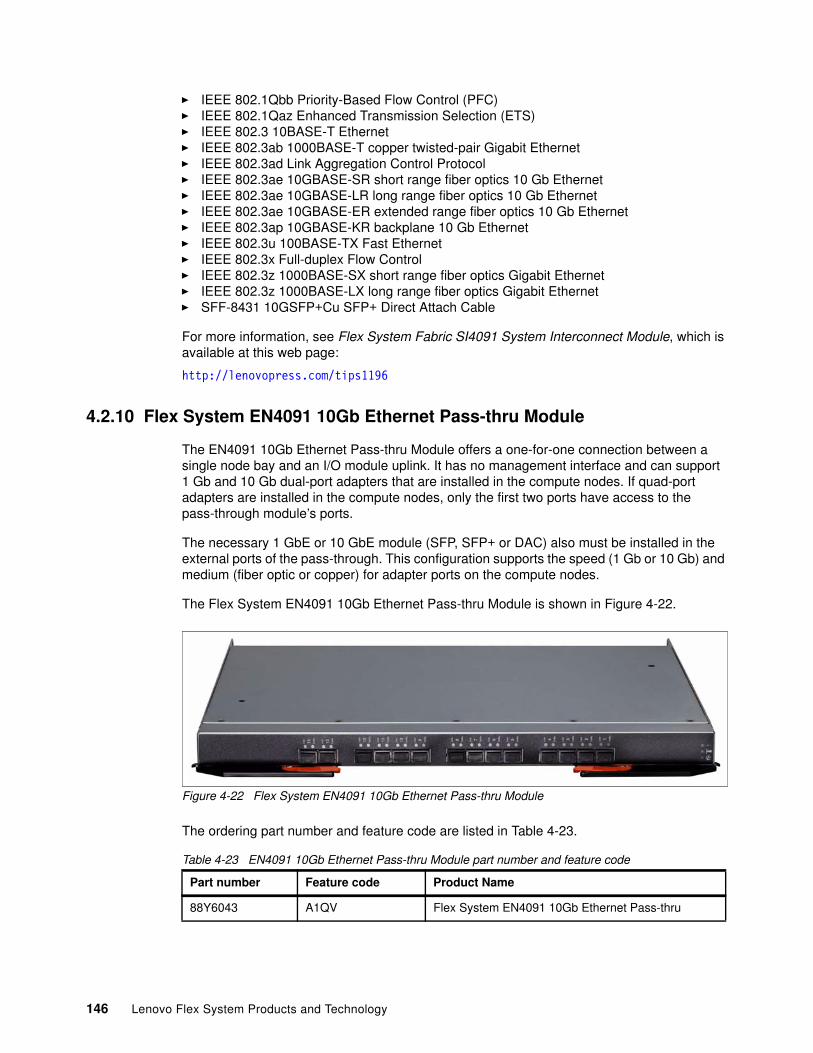
� IEEE 802.1Qbb Priority-Based Flow Control (PFC)� IEEE 802.1Qaz Enhanced Transmission Selection (ETS)� IEEE 802.3 10BASE-T Ethernet� IEEE 802.3ab 1000BASE-T copper twisted-pair Gigabit Ethernet� IEEE 802.3ad Link Aggregation Control Protocol� IEEE 802.3ae 10GBASE-SR short range fiber optics 10 Gb Ethernet� IEEE 802.3ae 10GBASE-LR long range fiber optics 10 Gb Ethernet� IEEE 802.3ae 10GBASE-ER extended range fiber optics 10 Gb Ethernet� IEEE 802.3ap 10GBASE-KR backplane 10 Gb Ethernet� IEEE 802.3u 100BASE-TX Fast Ethernet� IEEE 802.3x Full-duplex Flow Control � IEEE 802.3z 1000BASE-SX short range fiber optics Gigabit Ethernet� IEEE 802.3z 1000BASE-LX long range fiber optics Gigabit Ethernet� SFF-8431 10GSFP+Cu SFP+ Direct Attach Cable
For more information, see Flex System Fabric SI4091 System Interconnect Module, which is available at this web page:
http://lenovopress.com/tips1196
4.2.10 Flex System EN4091 10Gb Ethernet Pass-thru Module
The EN4091 10Gb Ethernet Pass-thru Module offers a one-for-one connection between a single node bay and an I/O module uplink. It has no management interface and can support 1 Gb and 10 Gb dual-port adapters that are installed in the compute nodes. If quad-port adapters are installed in the compute nodes, only the first two ports have access to the pass-through module’s ports.
The necessary 1 GbE or 10 GbE module (SFP, SFP+ or DAC) also must be installed in the external ports of the pass-through. This configuration supports the speed (1 Gb or 10 Gb) and medium (fiber optic or copper) for adapter ports on the compute nodes.
The Flex System EN4091 10Gb Ethernet Pass-thru Module is shown in Figure 4-22.
Figure 4-22 Flex System EN4091 10Gb Ethernet Pass-thru Module
The ordering part number and feature code are listed in Table 4-23.
Table 4-23 EN4091 10Gb Ethernet Pass-thru Module part number and feature code
Part number Feature code Product Name
88Y6043 A1QV Flex System EN4091 10Gb Ethernet Pass-thru
146 Lenovo Flex System Products and Technology
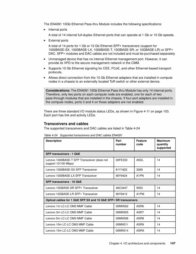
The EN4091 10Gb Ethernet Pass-thru Module includes the following specifications:
� Internal ports
A total of 14 internal full-duplex Ethernet ports that can operate at 1 Gb or 10 Gb speeds.
� External ports
A total of 14 ports for 1 Gb or 10 Gb Ethernet SFP+ transceivers (support for 1000BASE-SX, 1000BASE-LX, 1000BASE-T, 10GBASE-SR, or 10GBASE-LR) or SFP+ DAC. SFP+ modules and DAC cables are not included and must be purchased separately.
� Unmanaged device that has no internal Ethernet management port. However, it can provide its VPD to the secure management network in the CMM.
� Supports 10 Gb Ethernet signaling for CEE, FCoE, and other Ethernet-based transport protocols.
� Allows direct connection from the 10 Gb Ethernet adapters that are installed in compute nodes in a chassis to an externally located ToR switch or other external device.
There are three standard I/O module status LEDs, as shown in Figure 4-11 on page 103. Each port has link and activity LEDs.
Transceivers and cablesThe supported transceivers and DAC cables are listed in Table 4-24
Table 4-24 Supported transceivers and DAC cables EN4091
Considerations: The EN4091 10Gb Ethernet Pass-thru Module has only 14 internal ports. Therefore, only two ports on each compute node are enabled, one for each of two pass-through modules that are installed in the chassis. If four-port adapters are installed in the compute nodes, ports 3 and 4 on those adapters are not enabled.
Description Part number
Feature code
Maximum quantity supported
SFP transceivers - 1 GbE
Lenovo 1000BASE-T SFP Transceiver (does not support 10/100 Mbps)
00FE333 A5DL 14
Lenovo 1000BASE-SX SFP Transceiver 81Y1622 3269 14
Lenovo 1000BASE-LX SFP Transceiver 90Y9424 A1PN 14
SFP transceivers - 10 GbE
Lenovo 10GBASE-SR SFP+ Transceiver 46C3447 5053 14
Lenovo 10GBASE-LR SFP+ Transceiver 90Y9412 A1PM 14
Optical cables for 1 GbE SFP SX and 10 GbE SFP+ SR transceivers
Lenovo 1m LC-LC OM3 MMF Cable 00MN502 ASR6 14
Lenovo 3m LC-LC OM3 MMF Cable 00MN505 ASR7 14
Lenovo 5m LC-LC OM3 MMF Cable 00MN508 ASR8 14
Lenovo 10m LC-LC OM3 MMF Cable 00MN511 ASR9 14
Lenovo 15m LC-LC OM3 MMF Cable 00MN514 ASRA 14
Chapter 4. I/O architecture and components 147
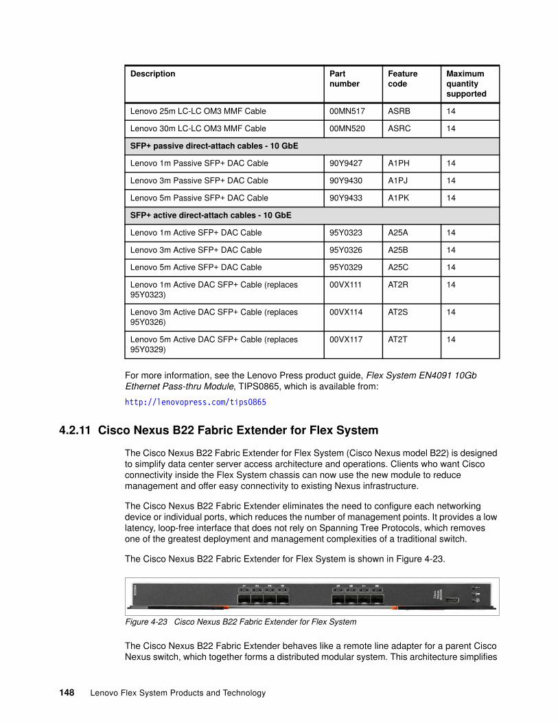
For more information, see the Lenovo Press product guide, Flex System EN4091 10Gb Ethernet Pass-thru Module, TIPS0865, which is available from:
http://lenovopress.com/tips0865
4.2.11 Cisco Nexus B22 Fabric Extender for Flex System
The Cisco Nexus B22 Fabric Extender for Flex System (Cisco Nexus model B22) is designed to simplify data center server access architecture and operations. Clients who want Cisco connectivity inside the Flex System chassis can now use the new module to reduce management and offer easy connectivity to existing Nexus infrastructure.
The Cisco Nexus B22 Fabric Extender eliminates the need to configure each networking device or individual ports, which reduces the number of management points. It provides a low latency, loop-free interface that does not rely on Spanning Tree Protocols, which removes one of the greatest deployment and management complexities of a traditional switch.
The Cisco Nexus B22 Fabric Extender for Flex System is shown in Figure 4-23.
Figure 4-23 Cisco Nexus B22 Fabric Extender for Flex System
The Cisco Nexus B22 Fabric Extender behaves like a remote line adapter for a parent Cisco Nexus switch, which together forms a distributed modular system. This architecture simplifies
Lenovo 25m LC-LC OM3 MMF Cable 00MN517 ASRB 14
Lenovo 30m LC-LC OM3 MMF Cable 00MN520 ASRC 14
SFP+ passive direct-attach cables - 10 GbE
Lenovo 1m Passive SFP+ DAC Cable 90Y9427 A1PH 14
Lenovo 3m Passive SFP+ DAC Cable 90Y9430 A1PJ 14
Lenovo 5m Passive SFP+ DAC Cable 90Y9433 A1PK 14
SFP+ active direct-attach cables - 10 GbE
Lenovo 1m Active SFP+ DAC Cable 95Y0323 A25A 14
Lenovo 3m Active SFP+ DAC Cable 95Y0326 A25B 14
Lenovo 5m Active SFP+ DAC Cable 95Y0329 A25C 14
Lenovo 1m Active DAC SFP+ Cable (replaces 95Y0323)
00VX111 AT2R 14
Lenovo 3m Active DAC SFP+ Cable (replaces 95Y0326)
00VX114 AT2S 14
Lenovo 5m Active DAC SFP+ Cable (replaces 95Y0329)
00VX117 AT2T 14
Description Part number
Feature code
Maximum quantity supported
148 Lenovo Flex System Products and Technology
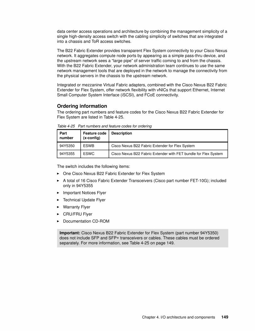
data center access operations and architecture by combining the management simplicity of a single high-density access switch with the cabling simplicity of switches that are integrated into a chassis and ToR access switches.
The B22 Fabric Extender provides transparent Flex System connectivity to your Cisco Nexus network. It aggregates compute node ports by appearing as a simple pass-thru device, and the upstream network sees a “large pipe” of server traffic coming to and from the chassis. With the B22 Fabric Extender, your network administration team continues to use the same network management tools that are deployed in the network to manage the connectivity from the physical servers in the chassis to the upstream network.
Integrated or mezzanine Virtual Fabric adapters, combined with the Cisco Nexus B22 Fabric Extender for Flex System, offer network flexibility with vNICs that support Ethernet, Internet Small Computer System Interface (iSCSI), and FCoE connectivity.
Ordering informationThe ordering part numbers and feature codes for the Cisco Nexus B22 Fabric Extender for Flex System are listed in Table 4-25.
Table 4-25 Part numbers and feature codes for ordering
The switch includes the following items:
� One Cisco Nexus B22 Fabric Extender for Flex System
� A total of 16 Cisco Fabric Extender Transceivers (Cisco part number FET-10G); included only in 94Y5355
� Important Notices Flyer
� Technical Update Flyer
� Warranty Flyer
� CRU/FRU Flyer
� Documentation CD-ROM
Part number
Feature code(x-config)
Description
94Y5350 ESWB Cisco Nexus B22 Fabric Extender for Flex System
94Y5355 ESWC Cisco Nexus B22 Fabric Extender with FET bundle for Flex System
Important: Cisco Nexus B22 Fabric Extender for Flex System (part number 94Y5350) does not include SFP and SFP+ transceivers or cables. These cables must be ordered separately. For more information, see Table 4-25 on page 149.
Chapter 4. I/O architecture and components 149
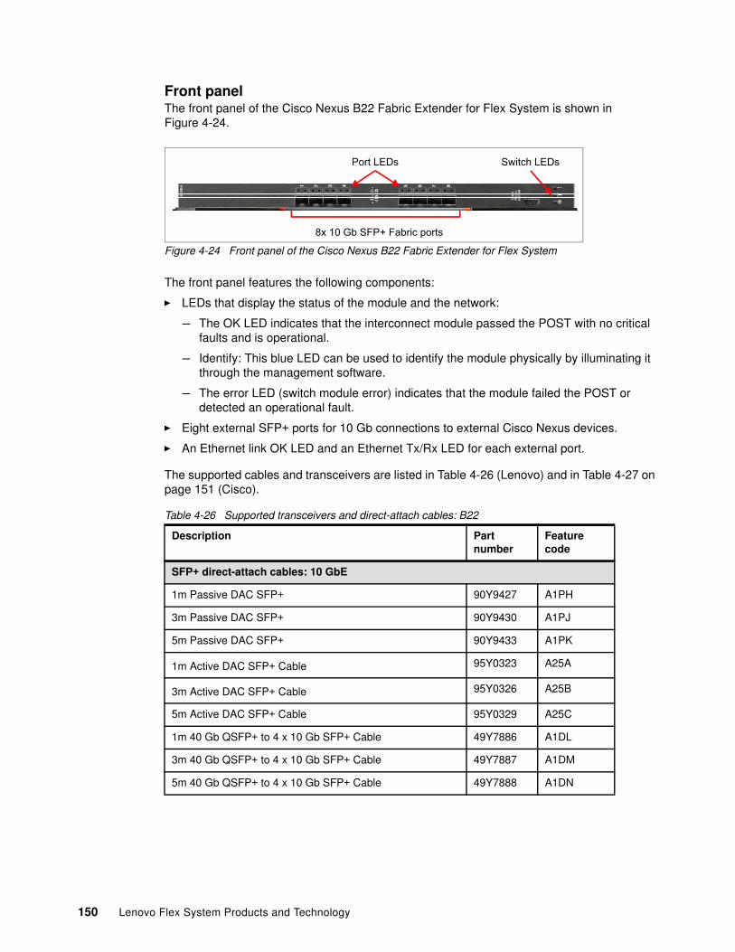
Front panelThe front panel of the Cisco Nexus B22 Fabric Extender for Flex System is shown in Figure 4-24.
Figure 4-24 Front panel of the Cisco Nexus B22 Fabric Extender for Flex System
The front panel features the following components:
� LEDs that display the status of the module and the network:
– The OK LED indicates that the interconnect module passed the POST with no critical faults and is operational.
– Identify: This blue LED can be used to identify the module physically by illuminating it through the management software.
– The error LED (switch module error) indicates that the module failed the POST or detected an operational fault.
� Eight external SFP+ ports for 10 Gb connections to external Cisco Nexus devices.
� An Ethernet link OK LED and an Ethernet Tx/Rx LED for each external port.
The supported cables and transceivers are listed in Table 4-26 (Lenovo) and in Table 4-27 on page 151 (Cisco).
Table 4-26 Supported transceivers and direct-attach cables: B22
Description Part number
Feature code
SFP+ direct-attach cables: 10 GbE
1m Passive DAC SFP+ 90Y9427 A1PH
3m Passive DAC SFP+ 90Y9430 A1PJ
5m Passive DAC SFP+ 90Y9433 A1PK
1m Active DAC SFP+ Cable 95Y0323 A25A
3m Active DAC SFP+ Cable 95Y0326 A25B
5m Active DAC SFP+ Cable 95Y0329 A25C
1m 40 Gb QSFP+ to 4 x 10 Gb SFP+ Cable 49Y7886 A1DL
3m 40 Gb QSFP+ to 4 x 10 Gb SFP+ Cable 49Y7887 A1DM
5m 40 Gb QSFP+ to 4 x 10 Gb SFP+ Cable 49Y7888 A1DN
8x 10 Gb SFP+ Fabric ports
Port LEDs Switch LEDs
150 Lenovo Flex System Products and Technology
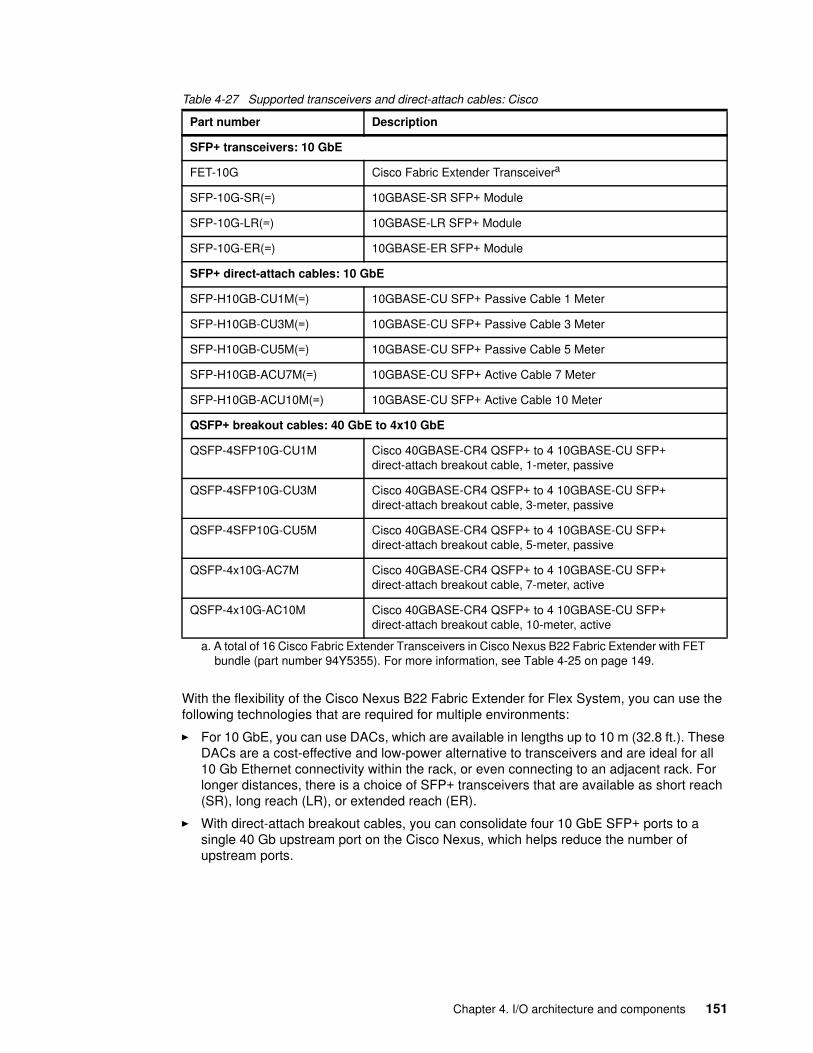
Table 4-27 Supported transceivers and direct-attach cables: Cisco
With the flexibility of the Cisco Nexus B22 Fabric Extender for Flex System, you can use the following technologies that are required for multiple environments:
� For 10 GbE, you can use DACs, which are available in lengths up to 10 m (32.8 ft.). These DACs are a cost-effective and low-power alternative to transceivers and are ideal for all 10 Gb Ethernet connectivity within the rack, or even connecting to an adjacent rack. For longer distances, there is a choice of SFP+ transceivers that are available as short reach (SR), long reach (LR), or extended reach (ER).
� With direct-attach breakout cables, you can consolidate four 10 GbE SFP+ ports to a single 40 Gb upstream port on the Cisco Nexus, which helps reduce the number of upstream ports.
Part number Description
SFP+ transceivers: 10 GbE
FET-10G Cisco Fabric Extender Transceivera
a. A total of 16 Cisco Fabric Extender Transceivers in Cisco Nexus B22 Fabric Extender with FET bundle (part number 94Y5355). For more information, see Table 4-25 on page 149.
SFP-10G-SR(=) 10GBASE-SR SFP+ Module
SFP-10G-LR(=) 10GBASE-LR SFP+ Module
SFP-10G-ER(=) 10GBASE-ER SFP+ Module
SFP+ direct-attach cables: 10 GbE
SFP-H10GB-CU1M(=) 10GBASE-CU SFP+ Passive Cable 1 Meter
SFP-H10GB-CU3M(=) 10GBASE-CU SFP+ Passive Cable 3 Meter
SFP-H10GB-CU5M(=) 10GBASE-CU SFP+ Passive Cable 5 Meter
SFP-H10GB-ACU7M(=) 10GBASE-CU SFP+ Active Cable 7 Meter
SFP-H10GB-ACU10M(=) 10GBASE-CU SFP+ Active Cable 10 Meter
QSFP+ breakout cables: 40 GbE to 4x10 GbE
QSFP-4SFP10G-CU1M Cisco 40GBASE-CR4 QSFP+ to 4 10GBASE-CU SFP+ direct-attach breakout cable, 1-meter, passive
QSFP-4SFP10G-CU3M Cisco 40GBASE-CR4 QSFP+ to 4 10GBASE-CU SFP+ direct-attach breakout cable, 3-meter, passive
QSFP-4SFP10G-CU5M Cisco 40GBASE-CR4 QSFP+ to 4 10GBASE-CU SFP+ direct-attach breakout cable, 5-meter, passive
QSFP-4x10G-AC7M Cisco 40GBASE-CR4 QSFP+ to 4 10GBASE-CU SFP+ direct-attach breakout cable, 7-meter, active
QSFP-4x10G-AC10M Cisco 40GBASE-CR4 QSFP+ to 4 10GBASE-CU SFP+ direct-attach breakout cable, 10-meter, active
Chapter 4. I/O architecture and components 151
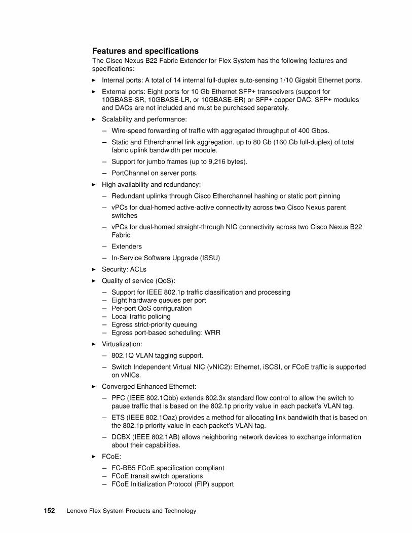
Features and specificationsThe Cisco Nexus B22 Fabric Extender for Flex System has the following features and specifications:
� Internal ports: A total of 14 internal full-duplex auto-sensing 1/10 Gigabit Ethernet ports.
� External ports: Eight ports for 10 Gb Ethernet SFP+ transceivers (support for 10GBASE-SR, 10GBASE-LR, or 10GBASE-ER) or SFP+ copper DAC. SFP+ modules and DACs are not included and must be purchased separately.
� Scalability and performance:
– Wire-speed forwarding of traffic with aggregated throughput of 400 Gbps.
– Static and Etherchannel link aggregation, up to 80 Gb (160 Gb full-duplex) of total fabric uplink bandwidth per module.
– Support for jumbo frames (up to 9,216 bytes).
– PortChannel on server ports.
� High availability and redundancy:
– Redundant uplinks through Cisco Etherchannel hashing or static port pinning
– vPCs for dual-homed active-active connectivity across two Cisco Nexus parent switches
– vPCs for dual-homed straight-through NIC connectivity across two Cisco Nexus B22 Fabric
– Extenders
– In-Service Software Upgrade (ISSU)
� Security: ACLs
� Quality of service (QoS):
– Support for IEEE 802.1p traffic classification and processing– Eight hardware queues per port– Per-port QoS configuration– Local traffic policing– Egress strict-priority queuing– Egress port-based scheduling: WRR
� Virtualization:
– 802.1Q VLAN tagging support.
– Switch Independent Virtual NIC (vNIC2): Ethernet, iSCSI, or FCoE traffic is supported on vNICs.
� Converged Enhanced Ethernet:
– PFC (IEEE 802.1Qbb) extends 802.3x standard flow control to allow the switch to pause traffic that is based on the 802.1p priority value in each packet's VLAN tag.
– ETS (IEEE 802.1Qaz) provides a method for allocating link bandwidth that is based on the 802.1p priority value in each packet's VLAN tag.
– DCBX (IEEE 802.1AB) allows neighboring network devices to exchange information about their capabilities.
� FCoE:
– FC-BB5 FCoE specification compliant– FCoE transit switch operations– FCoE Initialization Protocol (FIP) support
152 Lenovo Flex System Products and Technology
� Manageability:
– Fabric Extender management that uses in-band management
– SNMP v1, v2, and v3
– XML (NETCONF) support
– Cisco Discovery Protocol versions 1 and 2
– CiscoWorks support
– Cisco DCNM; the Cisco Nexus B22 is managed through the parent Cisco Nexus switch by using Cisco DCNM and standard SNMP, XML interfaces, and the CLI
� Monitoring:
– Switch LEDs for external port status and switch module status indication– Change tracking and remote logging with syslog feature– Remote monitoring– Cisco SPAN source on server ports– POST diagnostic tests
Standards supportedThe Cisco Nexus B22 Fabric Extenders support the following standards:
� IEEE 802.1AB Data Center Bridging Capability Exchange Protocol (DCBX)� IEEE 802.1p Class of Service (CoS) prioritization� IEEE 802.1Q Tagged VLAN (frame tagging on all ports when VLANs are enabled)� IEEE 802.1Qbb PFC� IEEE 802.1Qaz ETS� IEEE 802.3 Ethernet� IEEE 802.3ae 10GBASE-SR short range fiber optics 10 Gb Ethernet� IEEE 802.3ae 10GBASE-LR long range fiber optics 10 Gb Ethernet� IEEE 802.3ae 10GBASE-ER extended range fiber optics 10 Gb Ethernet� IEEE 802.3ap 10GBASE-KR backplane 10 Gb Ethernet� IEEE 802.3x Full-duplex Flow Control� SFF-8431 10GSFP+Cu SFP+ Direct Attach Cable
For more information, see Cisco Nexus B22 Fabric Extender for Flex System, TIPS1086, which is available at this web page:
http://lenovopress.com/tips1086
4.2.12 Flex System EN2092 1Gb Ethernet Scalable Switch
The EN2092 1Gb Ethernet Switch provides support for L2/L3 switching and routing. The switch includes the following ports:
� Up to 28 internal 1 Gb ports� Up to 20 external 1 Gb ports (RJ45 connectors)� Up to 4 external 10 Gb uplink ports (SFP+ connectors)
Chapter 4. I/O architecture and components 153
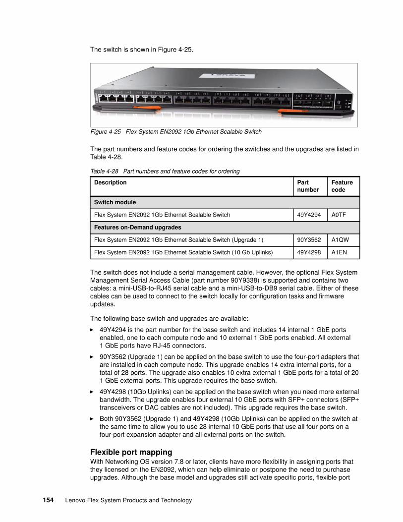
The switch is shown in Figure 4-25.
Figure 4-25 Flex System EN2092 1Gb Ethernet Scalable Switch
The part numbers and feature codes for ordering the switches and the upgrades are listed in Table 4-28.
Table 4-28 Part numbers and feature codes for ordering
The switch does not include a serial management cable. However, the optional Flex System Management Serial Access Cable (part number 90Y9338) is supported and contains two cables: a mini-USB-to-RJ45 serial cable and a mini-USB-to-DB9 serial cable. Either of these cables can be used to connect to the switch locally for configuration tasks and firmware updates.
The following base switch and upgrades are available:
� 49Y4294 is the part number for the base switch and includes 14 internal 1 GbE ports enabled, one to each compute node and 10 external 1 GbE ports enabled. All external 1 GbE ports have RJ-45 connectors.
� 90Y3562 (Upgrade 1) can be applied on the base switch to use the four-port adapters that are installed in each compute node. This upgrade enables 14 extra internal ports, for a total of 28 ports. The upgrade also enables 10 extra external 1 GbE ports for a total of 20 1 GbE external ports. This upgrade requires the base switch.
� 49Y4298 (10Gb Uplinks) can be applied on the base switch when you need more external bandwidth. The upgrade enables four external 10 GbE ports with SFP+ connectors (SFP+ transceivers or DAC cables are not included). This upgrade requires the base switch.
� Both 90Y3562 (Upgrade 1) and 49Y4298 (10Gb Uplinks) can be applied on the switch at the same time to allow you to use 28 internal 10 GbE ports that use all four ports on a four-port expansion adapter and all external ports on the switch.
Flexible port mapping With Networking OS version 7.8 or later, clients have more flexibility in assigning ports that they licensed on the EN2092, which can help eliminate or postpone the need to purchase upgrades. Although the base model and upgrades still activate specific ports, flexible port
Description Partnumber
Featurecode
Switch module
Flex System EN2092 1Gb Ethernet Scalable Switch 49Y4294 A0TF
Features on-Demand upgrades
Flex System EN2092 1Gb Ethernet Scalable Switch (Upgrade 1) 90Y3562 A1QW
Flex System EN2092 1Gb Ethernet Scalable Switch (10 Gb Uplinks) 49Y4298 A1EN
154 Lenovo Flex System Products and Technology
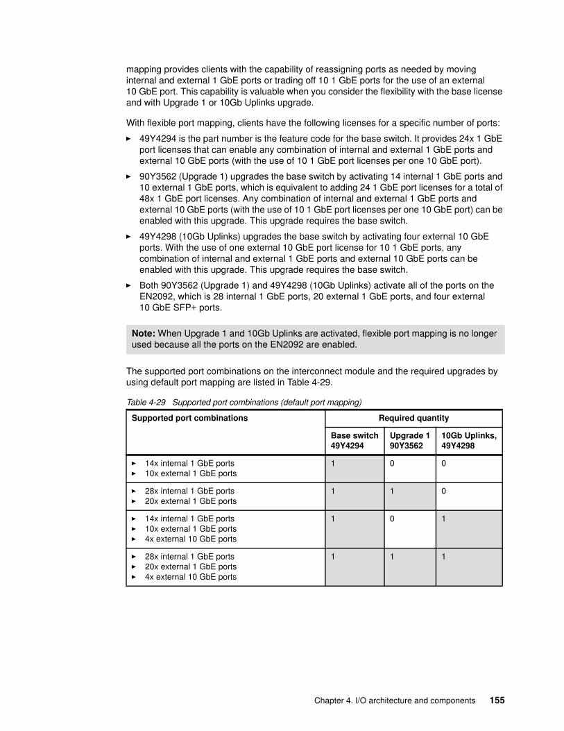
mapping provides clients with the capability of reassigning ports as needed by moving internal and external 1 GbE ports or trading off 10 1 GbE ports for the use of an external 10 GbE port. This capability is valuable when you consider the flexibility with the base license and with Upgrade 1 or 10Gb Uplinks upgrade.
With flexible port mapping, clients have the following licenses for a specific number of ports:
� 49Y4294 is the part number is the feature code for the base switch. It provides 24x 1 GbE port licenses that can enable any combination of internal and external 1 GbE ports and external 10 GbE ports (with the use of 10 1 GbE port licenses per one 10 GbE port).
� 90Y3562 (Upgrade 1) upgrades the base switch by activating 14 internal 1 GbE ports and 10 external 1 GbE ports, which is equivalent to adding 24 1 GbE port licenses for a total of 48x 1 GbE port licenses. Any combination of internal and external 1 GbE ports and external 10 GbE ports (with the use of 10 1 GbE port licenses per one 10 GbE port) can be enabled with this upgrade. This upgrade requires the base switch.
� 49Y4298 (10Gb Uplinks) upgrades the base switch by activating four external 10 GbE ports. With the use of one external 10 GbE port license for 10 1 GbE ports, any combination of internal and external 1 GbE ports and external 10 GbE ports can be enabled with this upgrade. This upgrade requires the base switch.
� Both 90Y3562 (Upgrade 1) and 49Y4298 (10Gb Uplinks) activate all of the ports on the EN2092, which is 28 internal 1 GbE ports, 20 external 1 GbE ports, and four external 10 GbE SFP+ ports.
The supported port combinations on the interconnect module and the required upgrades by using default port mapping are listed in Table 4-29.
Table 4-29 Supported port combinations (default port mapping)
Note: When Upgrade 1 and 10Gb Uplinks are activated, flexible port mapping is no longer used because all the ports on the EN2092 are enabled.
Supported port combinations Required quantity
Base switch49Y4294
Upgrade 190Y3562
10Gb Uplinks,49Y4298
� 14x internal 1 GbE ports� 10x external 1 GbE ports
1 0 0
� 28x internal 1 GbE ports� 20x external 1 GbE ports
1 1 0
� 14x internal 1 GbE ports� 10x external 1 GbE ports� 4x external 10 GbE ports
1 0 1
� 28x internal 1 GbE ports� 20x external 1 GbE ports� 4x external 10 GbE ports
1 1 1
Chapter 4. I/O architecture and components 155
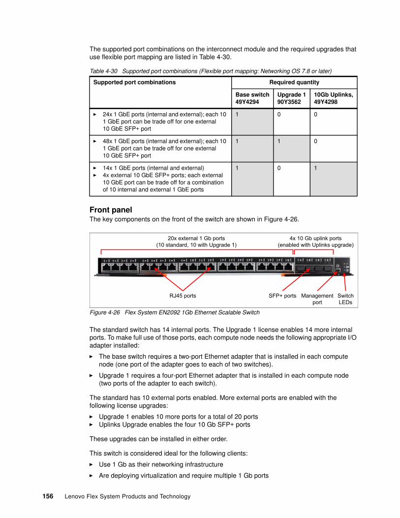
The supported port combinations on the interconnect module and the required upgrades that use flexible port mapping are listed in Table 4-30.
Table 4-30 Supported port combinations (Flexible port mapping: Networking OS 7.8 or later)
Front panelThe key components on the front of the switch are shown in Figure 4-26.
Figure 4-26 Flex System EN2092 1Gb Ethernet Scalable Switch
The standard switch has 14 internal ports. The Upgrade 1 license enables 14 more internal ports. To make full use of those ports, each compute node needs the following appropriate I/O adapter installed:
� The base switch requires a two-port Ethernet adapter that is installed in each compute node (one port of the adapter goes to each of two switches).
� Upgrade 1 requires a four-port Ethernet adapter that is installed in each compute node (two ports of the adapter to each switch).
The standard has 10 external ports enabled. More external ports are enabled with the following license upgrades:
� Upgrade 1 enables 10 more ports for a total of 20 ports� Uplinks Upgrade enables the four 10 Gb SFP+ ports
These upgrades can be installed in either order.
This switch is considered ideal for the following clients:
� Use 1 Gb as their networking infrastructure
� Are deploying virtualization and require multiple 1 Gb ports
Supported port combinations Required quantity
Base switch49Y4294
Upgrade 190Y3562
10Gb Uplinks,49Y4298
� 24x 1 GbE ports (internal and external); each 10 1 GbE port can be trade off for one external 10 GbE SFP+ port
1 0 0
� 48x 1 GbE ports (internal and external); each 10 1 GbE port can be trade off for one external 10 GbE SFP+ port
1 1 0
� 14x 1 GbE ports (internal and external)� 4x external 10 GbE SFP+ ports; each external
10 GbE port can be trade off for a combination of 10 internal and external 1 GbE ports
1 0 1
20x external 1 Gb ports (10 standard, 10 with Upgrade 1)
4x 10 Gb uplink ports (enabled with Uplinks upgrade)
RJ45 ports SFP+ ports Managementport
SwitchLEDs
156 Lenovo Flex System Products and Technology
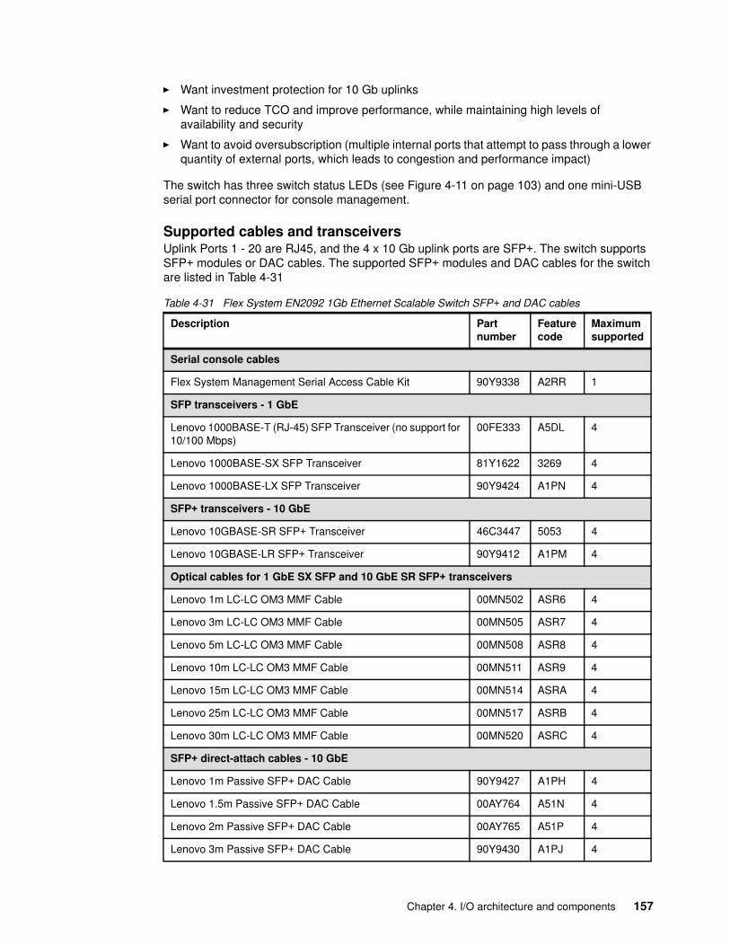
� Want investment protection for 10 Gb uplinks
� Want to reduce TCO and improve performance, while maintaining high levels of availability and security
� Want to avoid oversubscription (multiple internal ports that attempt to pass through a lower quantity of external ports, which leads to congestion and performance impact)
The switch has three switch status LEDs (see Figure 4-11 on page 103) and one mini-USB serial port connector for console management.
Supported cables and transceiversUplink Ports 1 - 20 are RJ45, and the 4 x 10 Gb uplink ports are SFP+. The switch supports SFP+ modules or DAC cables. The supported SFP+ modules and DAC cables for the switch are listed in Table 4-31
Table 4-31 Flex System EN2092 1Gb Ethernet Scalable Switch SFP+ and DAC cables
Description Partnumber
Featurecode
Maximumsupported
Serial console cables
Flex System Management Serial Access Cable Kit 90Y9338 A2RR 1
SFP transceivers - 1 GbE
Lenovo 1000BASE-T (RJ-45) SFP Transceiver (no support for 10/100 Mbps)
00FE333 A5DL 4
Lenovo 1000BASE-SX SFP Transceiver 81Y1622 3269 4
Lenovo 1000BASE-LX SFP Transceiver 90Y9424 A1PN 4
SFP+ transceivers - 10 GbE
Lenovo 10GBASE-SR SFP+ Transceiver 46C3447 5053 4
Lenovo 10GBASE-LR SFP+ Transceiver 90Y9412 A1PM 4
Optical cables for 1 GbE SX SFP and 10 GbE SR SFP+ transceivers
Lenovo 1m LC-LC OM3 MMF Cable 00MN502 ASR6 4
Lenovo 3m LC-LC OM3 MMF Cable 00MN505 ASR7 4
Lenovo 5m LC-LC OM3 MMF Cable 00MN508 ASR8 4
Lenovo 10m LC-LC OM3 MMF Cable 00MN511 ASR9 4
Lenovo 15m LC-LC OM3 MMF Cable 00MN514 ASRA 4
Lenovo 25m LC-LC OM3 MMF Cable 00MN517 ASRB 4
Lenovo 30m LC-LC OM3 MMF Cable 00MN520 ASRC 4
SFP+ direct-attach cables - 10 GbE
Lenovo 1m Passive SFP+ DAC Cable 90Y9427 A1PH 4
Lenovo 1.5m Passive SFP+ DAC Cable 00AY764 A51N 4
Lenovo 2m Passive SFP+ DAC Cable 00AY765 A51P 4
Lenovo 3m Passive SFP+ DAC Cable 90Y9430 A1PJ 4
Chapter 4. I/O architecture and components 157
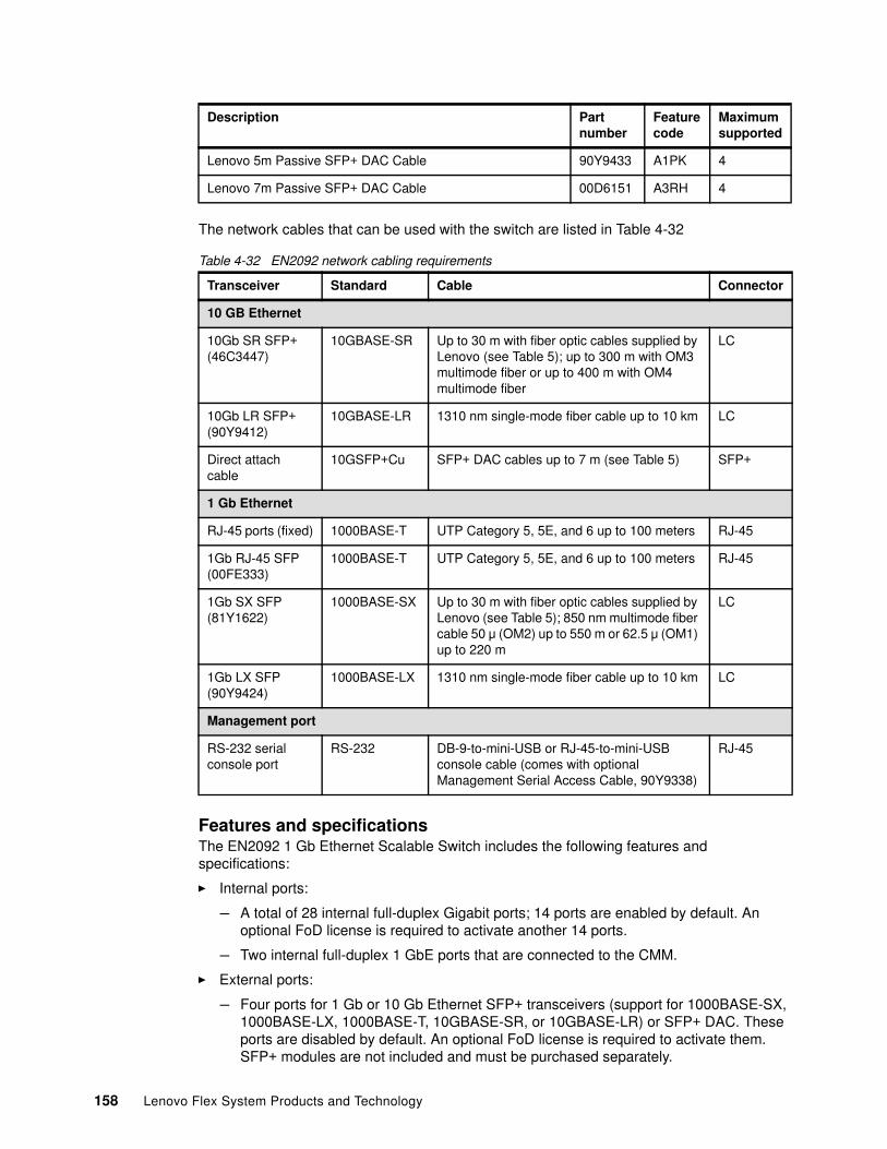
The network cables that can be used with the switch are listed in Table 4-32
Table 4-32 EN2092 network cabling requirements
Features and specificationsThe EN2092 1 Gb Ethernet Scalable Switch includes the following features and specifications:
� Internal ports:
– A total of 28 internal full-duplex Gigabit ports; 14 ports are enabled by default. An optional FoD license is required to activate another 14 ports.
– Two internal full-duplex 1 GbE ports that are connected to the CMM.
� External ports:
– Four ports for 1 Gb or 10 Gb Ethernet SFP+ transceivers (support for 1000BASE-SX, 1000BASE-LX, 1000BASE-T, 10GBASE-SR, or 10GBASE-LR) or SFP+ DAC. These ports are disabled by default. An optional FoD license is required to activate them. SFP+ modules are not included and must be purchased separately.
Lenovo 5m Passive SFP+ DAC Cable 90Y9433 A1PK 4
Lenovo 7m Passive SFP+ DAC Cable 00D6151 A3RH 4
Transceiver Standard Cable Connector
10 GB Ethernet
10Gb SR SFP+ (46C3447)
10GBASE-SR Up to 30 m with fiber optic cables supplied by Lenovo (see Table 5); up to 300 m with OM3 multimode fiber or up to 400 m with OM4 multimode fiber
LC
10Gb LR SFP+ (90Y9412)
10GBASE-LR 1310 nm single-mode fiber cable up to 10 km LC
Direct attach cable
10GSFP+Cu SFP+ DAC cables up to 7 m (see Table 5) SFP+
1 Gb Ethernet
RJ-45 ports (fixed) 1000BASE-T UTP Category 5, 5E, and 6 up to 100 meters RJ-45
1Gb RJ-45 SFP (00FE333)
1000BASE-T UTP Category 5, 5E, and 6 up to 100 meters RJ-45
1Gb SX SFP (81Y1622)
1000BASE-SX Up to 30 m with fiber optic cables supplied by Lenovo (see Table 5); 850 nm multimode fiber cable 50 μ (OM2) up to 550 m or 62.5 μ (OM1) up to 220 m
LC
1Gb LX SFP (90Y9424)
1000BASE-LX 1310 nm single-mode fiber cable up to 10 km LC
Management port
RS-232 serial console port
RS-232 DB-9-to-mini-USB or RJ-45-to-mini-USB console cable (comes with optional Management Serial Access Cable, 90Y9338)
RJ-45
Description Partnumber
Featurecode
Maximumsupported
158 Lenovo Flex System Products and Technology
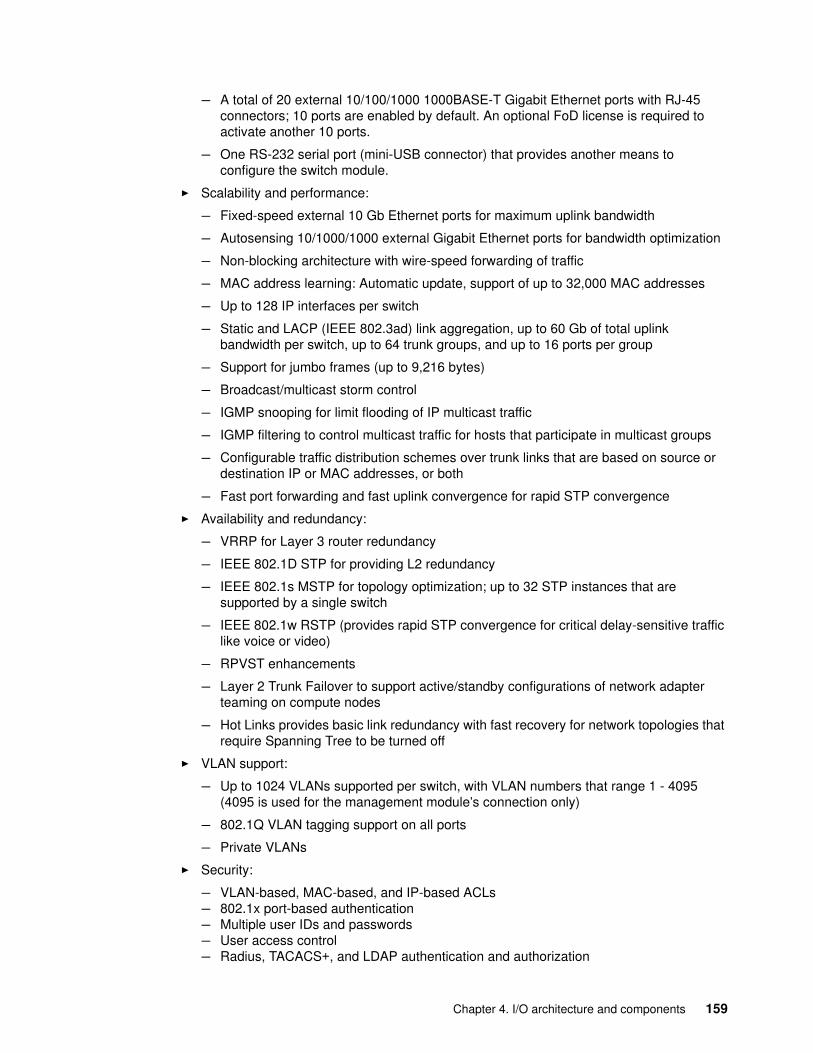
– A total of 20 external 10/100/1000 1000BASE-T Gigabit Ethernet ports with RJ-45 connectors; 10 ports are enabled by default. An optional FoD license is required to activate another 10 ports.
– One RS-232 serial port (mini-USB connector) that provides another means to configure the switch module.
� Scalability and performance:
– Fixed-speed external 10 Gb Ethernet ports for maximum uplink bandwidth
– Autosensing 10/1000/1000 external Gigabit Ethernet ports for bandwidth optimization
– Non-blocking architecture with wire-speed forwarding of traffic
– MAC address learning: Automatic update, support of up to 32,000 MAC addresses
– Up to 128 IP interfaces per switch
– Static and LACP (IEEE 802.3ad) link aggregation, up to 60 Gb of total uplink bandwidth per switch, up to 64 trunk groups, and up to 16 ports per group
– Support for jumbo frames (up to 9,216 bytes)
– Broadcast/multicast storm control
– IGMP snooping for limit flooding of IP multicast traffic
– IGMP filtering to control multicast traffic for hosts that participate in multicast groups
– Configurable traffic distribution schemes over trunk links that are based on source or destination IP or MAC addresses, or both
– Fast port forwarding and fast uplink convergence for rapid STP convergence
� Availability and redundancy:
– VRRP for Layer 3 router redundancy
– IEEE 802.1D STP for providing L2 redundancy
– IEEE 802.1s MSTP for topology optimization; up to 32 STP instances that are supported by a single switch
– IEEE 802.1w RSTP (provides rapid STP convergence for critical delay-sensitive traffic like voice or video)
– RPVST enhancements
– Layer 2 Trunk Failover to support active/standby configurations of network adapter teaming on compute nodes
– Hot Links provides basic link redundancy with fast recovery for network topologies that require Spanning Tree to be turned off
� VLAN support:
– Up to 1024 VLANs supported per switch, with VLAN numbers that range 1 - 4095 (4095 is used for the management module’s connection only)
– 802.1Q VLAN tagging support on all ports
– Private VLANs
� Security:
– VLAN-based, MAC-based, and IP-based ACLs– 802.1x port-based authentication– Multiple user IDs and passwords– User access control– Radius, TACACS+, and LDAP authentication and authorization
Chapter 4. I/O architecture and components 159

� QoS:
– Support for IEEE 802.1p, IP ToS/DSCP, and ACL-based (MAC/IP source and destination addresses, VLANs) traffic classification and processing
– Traffic shaping and remarking that is based on defined policies
– Eight WRR priority queues per port for processing qualified traffic
� IP v4 Layer 3 functions:
– Host management
– IP forwarding
– IP filtering with ACLs; up to 896 ACLs supported
– VRRP for router redundancy
– Support for up to 128 static routes
– Routing protocol support (RIP v1, RIP v2, OSPF v2, and BGP-4); up to 2048 entries in a routing table
– Support for DHCP Relay
– Support for IGMP snooping and IGMP relay
– Support for PIM-SM and PIM-DM
� IP v6 Layer 3 functions:
– IPv6 host management (except default switch management IP address)– IPv6 forwarding– Up to 128 static routes– Support for OSPF v3 routing protocol– IPv6 filtering with ACLs
� Virtualization: VMready
� Manageability:
– SNMP V1, V2, and V3– HTTP browser GUI– Telnet interface for CLI– SSH– Serial interface for CLI– Scriptable CLI– Firmware image update (TFTP and FTP)– NTP for switch clock synchronization
� Monitoring:
– Switch LEDs for external port status and switch module status indication
– RMON agent to collect statistics and proactively monitor switch performance
– Port mirroring for analyzing network traffic that passes through the switch
– Change tracking and remote logging with the syslog feature
– Support for the sFLOW agent for monitoring traffic in data networks (separate sFLOW analyzer is required elsewhere)
– POST diagnostic functions
For more information, see the Lenovo Press product guide, Flex System EN2092 1Gb Ethernet Scalable Switch, TIPS0861, which is available from:
http://lenovopress.com/tips0861
160 Lenovo Flex System Products and Technology
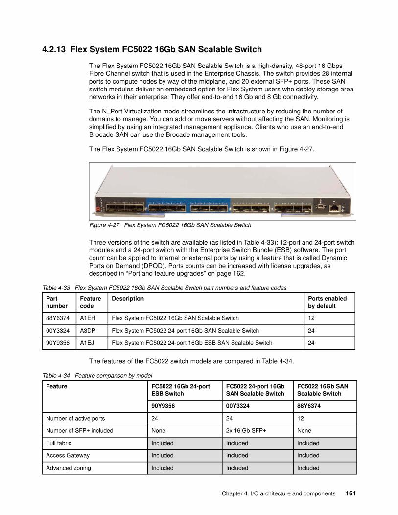
4.2.13 Flex System FC5022 16Gb SAN Scalable Switch
The Flex System FC5022 16Gb SAN Scalable Switch is a high-density, 48-port 16 Gbps Fibre Channel switch that is used in the Enterprise Chassis. The switch provides 28 internal ports to compute nodes by way of the midplane, and 20 external SFP+ ports. These SAN switch modules deliver an embedded option for Flex System users who deploy storage area networks in their enterprise. They offer end-to-end 16 Gb and 8 Gb connectivity.
The N_Port Virtualization mode streamlines the infrastructure by reducing the number of domains to manage. You can add or move servers without affecting the SAN. Monitoring is simplified by using an integrated management appliance. Clients who use an end-to-end Brocade SAN can use the Brocade management tools.
The Flex System FC5022 16Gb SAN Scalable Switch is shown in Figure 4-27.
Figure 4-27 Flex System FC5022 16Gb SAN Scalable Switch
Three versions of the switch are available (as listed in Table 4-33): 12-port and 24-port switch modules and a 24-port switch with the Enterprise Switch Bundle (ESB) software. The port count can be applied to internal or external ports by using a feature that is called Dynamic Ports on Demand (DPOD). Ports counts can be increased with license upgrades, as described in “Port and feature upgrades” on page 162.
Table 4-33 Flex System FC5022 16Gb SAN Scalable Switch part numbers and feature codes
The features of the FC5022 switch models are compared in Table 4-34.
Table 4-34 Feature comparison by model
Partnumber
Featurecode
Description Ports enabledby default
88Y6374 A1EH Flex System FC5022 16Gb SAN Scalable Switch 12
00Y3324 A3DP Flex System FC5022 24-port 16Gb SAN Scalable Switch 24
90Y9356 A1EJ Flex System FC5022 24-port 16Gb ESB SAN Scalable Switch 24
Feature FC5022 16Gb 24-portESB Switch
FC5022 24-port 16GbSAN Scalable Switch
FC5022 16Gb SANScalable Switch
90Y9356 00Y3324 88Y6374
Number of active ports 24 24 12
Number of SFP+ included None 2x 16 Gb SFP+ None
Full fabric Included Included Included
Access Gateway Included Included Included
Advanced zoning Included Included Included
Chapter 4. I/O architecture and components 161
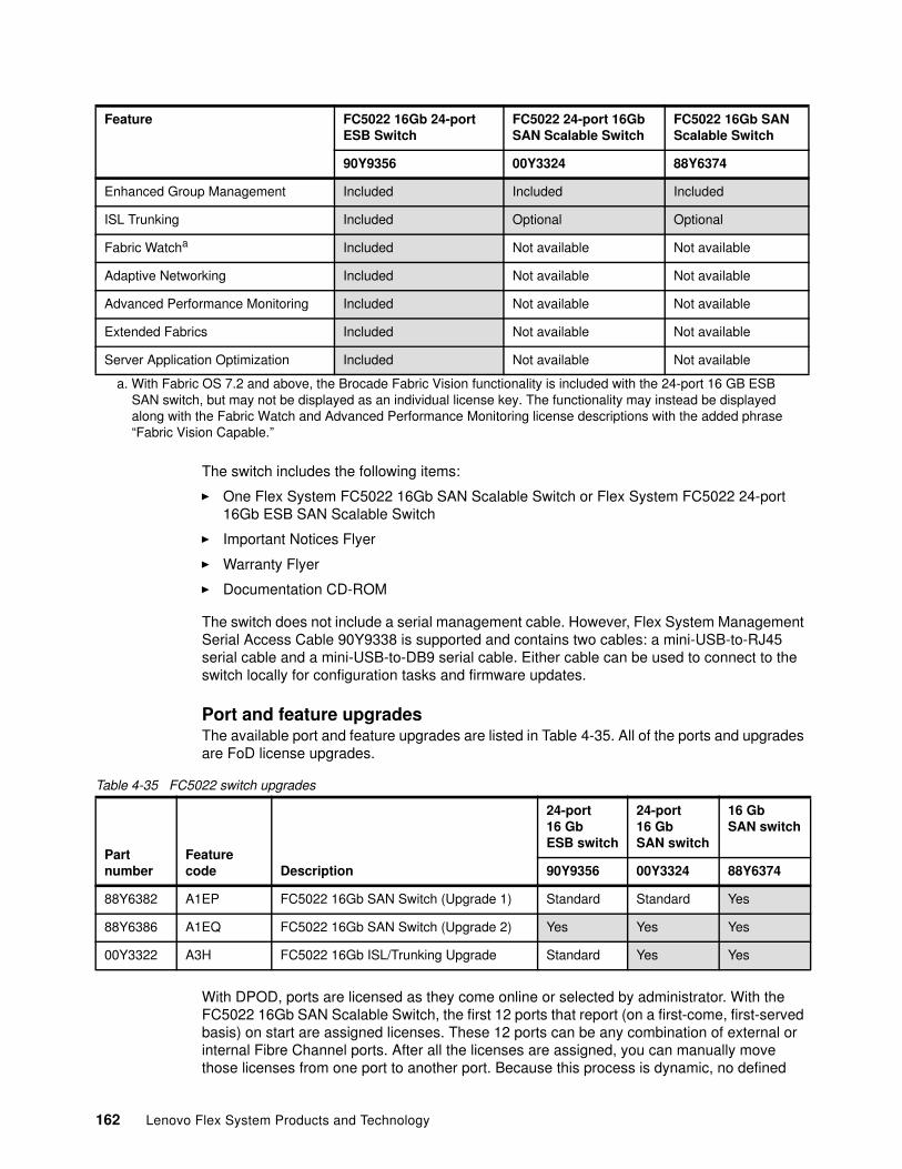
The switch includes the following items:
� One Flex System FC5022 16Gb SAN Scalable Switch or Flex System FC5022 24-port 16Gb ESB SAN Scalable Switch
� Important Notices Flyer
� Warranty Flyer
� Documentation CD-ROM
The switch does not include a serial management cable. However, Flex System Management Serial Access Cable 90Y9338 is supported and contains two cables: a mini-USB-to-RJ45 serial cable and a mini-USB-to-DB9 serial cable. Either cable can be used to connect to the switch locally for configuration tasks and firmware updates.
Port and feature upgradesThe available port and feature upgrades are listed in Table 4-35. All of the ports and upgrades are FoD license upgrades.
Table 4-35 FC5022 switch upgrades
With DPOD, ports are licensed as they come online or selected by administrator. With the FC5022 16Gb SAN Scalable Switch, the first 12 ports that report (on a first-come, first-served basis) on start are assigned licenses. These 12 ports can be any combination of external or internal Fibre Channel ports. After all the licenses are assigned, you can manually move those licenses from one port to another port. Because this process is dynamic, no defined
Enhanced Group Management Included Included Included
ISL Trunking Included Optional Optional
Fabric Watcha Included Not available Not available
Adaptive Networking Included Not available Not available
Advanced Performance Monitoring Included Not available Not available
Extended Fabrics Included Not available Not available
Server Application Optimization Included Not available Not available
a. With Fabric OS 7.2 and above, the Brocade Fabric Vision functionality is included with the 24-port 16 GB ESB SAN switch, but may not be displayed as an individual license key. The functionality may instead be displayed along with the Fabric Watch and Advanced Performance Monitoring license descriptions with the added phrase “Fabric Vision Capable.”
Feature FC5022 16Gb 24-portESB Switch
FC5022 24-port 16GbSAN Scalable Switch
FC5022 16Gb SANScalable Switch
90Y9356 00Y3324 88Y6374
Partnumber
Featurecode Description
24-port 16 Gb ESB switch
24-port 16 GbSAN switch
16 GbSAN switch
90Y9356 00Y3324 88Y6374
88Y6382 A1EP FC5022 16Gb SAN Switch (Upgrade 1) Standard Standard Yes
88Y6386 A1EQ FC5022 16Gb SAN Switch (Upgrade 2) Yes Yes Yes
00Y3322 A3H FC5022 16Gb ISL/Trunking Upgrade Standard Yes Yes
162 Lenovo Flex System Products and Technology
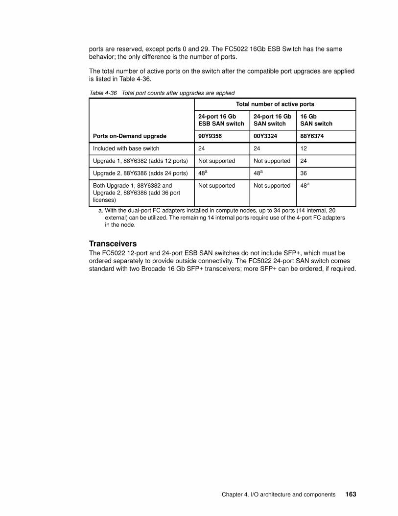
ports are reserved, except ports 0 and 29. The FC5022 16Gb ESB Switch has the same behavior; the only difference is the number of ports.
The total number of active ports on the switch after the compatible port upgrades are applied is listed in Table 4-36.
Table 4-36 Total port counts after upgrades are applied
TransceiversThe FC5022 12-port and 24-port ESB SAN switches do not include SFP+, which must be ordered separately to provide outside connectivity. The FC5022 24-port SAN switch comes standard with two Brocade 16 Gb SFP+ transceivers; more SFP+ can be ordered, if required.
Ports on-Demand upgrade
Total number of active ports
24-port 16 Gb ESB SAN switch
24-port 16 GbSAN switch
16 GbSAN switch
90Y9356 00Y3324 88Y6374
Included with base switch 24 24 12
Upgrade 1, 88Y6382 (adds 12 ports) Not supported Not supported 24
Upgrade 2, 88Y6386 (adds 24 ports) 48a
a. With the dual-port FC adapters installed in compute nodes, up to 34 ports (14 internal, 20 external) can be utilized. The remaining 14 internal ports require use of the 4-port FC adapters in the node.
48a 36
Both Upgrade 1, 88Y6382 and Upgrade 2, 88Y6386 (add 36 port licenses)
Not supported Not supported 48a
Chapter 4. I/O architecture and components 163
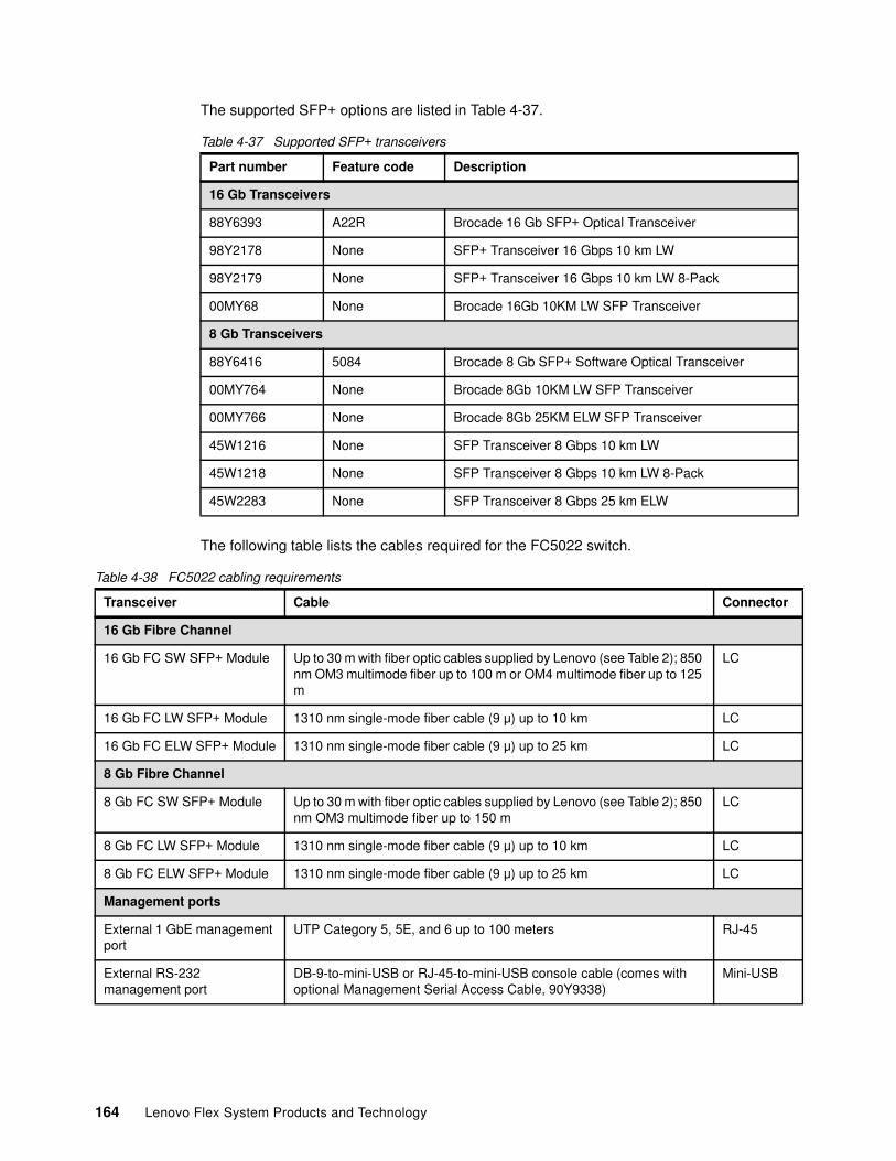
The supported SFP+ options are listed in Table 4-37.
Table 4-37 Supported SFP+ transceivers
The following table lists the cables required for the FC5022 switch.
Table 4-38 FC5022 cabling requirements
Part number Feature code Description
16 Gb Transceivers
88Y6393 A22R Brocade 16 Gb SFP+ Optical Transceiver
98Y2178 None SFP+ Transceiver 16 Gbps 10 km LW
98Y2179 None SFP+ Transceiver 16 Gbps 10 km LW 8-Pack
00MY68 None Brocade 16Gb 10KM LW SFP Transceiver
8 Gb Transceivers
88Y6416 5084 Brocade 8 Gb SFP+ Software Optical Transceiver
00MY764 None Brocade 8Gb 10KM LW SFP Transceiver
00MY766 None Brocade 8Gb 25KM ELW SFP Transceiver
45W1216 None SFP Transceiver 8 Gbps 10 km LW
45W1218 None SFP Transceiver 8 Gbps 10 km LW 8-Pack
45W2283 None SFP Transceiver 8 Gbps 25 km ELW
Transceiver Cable Connector
16 Gb Fibre Channel
16 Gb FC SW SFP+ Module Up to 30 m with fiber optic cables supplied by Lenovo (see Table 2); 850 nm OM3 multimode fiber up to 100 m or OM4 multimode fiber up to 125 m
LC
16 Gb FC LW SFP+ Module 1310 nm single-mode fiber cable (9 μ) up to 10 km LC
16 Gb FC ELW SFP+ Module 1310 nm single-mode fiber cable (9 μ) up to 25 km LC
8 Gb Fibre Channel
8 Gb FC SW SFP+ Module Up to 30 m with fiber optic cables supplied by Lenovo (see Table 2); 850 nm OM3 multimode fiber up to 150 m
LC
8 Gb FC LW SFP+ Module 1310 nm single-mode fiber cable (9 μ) up to 10 km LC
8 Gb FC ELW SFP+ Module 1310 nm single-mode fiber cable (9 μ) up to 25 km LC
Management ports
External 1 GbE management port
UTP Category 5, 5E, and 6 up to 100 meters RJ-45
External RS-232 management port
DB-9-to-mini-USB or RJ-45-to-mini-USB console cable (comes with optional Management Serial Access Cable, 90Y9338)
Mini-USB
164 Lenovo Flex System Products and Technology
BenefitsThe switches offer the following key benefits:
� Exceptional price and performance for growing SAN workloads
The FC5022 16Gb SAN Scalable Switch delivers exceptional price and performance through a combination of market-leading 1,600 MBps throughput per port and an affordable high-density form factor. The 48 FC ports produce an aggregate 768 Gbps full-duplex throughput and any external eight ports can be trunked for 128 Gbps inter-switch links (ISLs). Because 16 Gbps port technology dramatically reduces the number of ports and associated optics and cabling that is required through 8/4 Gbps consolidation, the cost savings and simplification benefits are substantial.
� Accelerating fabric deployment and serviceability with diagnostic ports
Diagnostic Ports (D_Ports) are a new port type that is supported by the FC5022 16Gb SAN Scalable Switch. They enable administrators to quickly identify and isolate 16 Gbps optics, port, and cable problems, which reduces fabric deployment and diagnostic times. If the optical media is found to be the source of the problem, it can be transparently replaced because 16 Gbps optics are hot-pluggable.
� A building block for virtualized, private cloud storage
The FC5022 16Gb SAN Scalable Switch supports multi-tenancy in cloud environments through VM-aware end-to-end visibility and monitoring, QoS, and fabric-based advanced zoning features. The FC5022 16Gb SAN Scalable Switch enables secure distance extension to virtual private or hybrid clouds with dark fiber support. They also enable in-flight encryption and data compression. Internal fault-tolerant and enterprise-class reliability, availability, and serviceability (RAS) features help minimize downtime to support mission-critical cloud environments.
� Simplified and optimized interconnect with Brocade Access Gateway
The FC5022 16Gb SAN Scalable Switch can be deployed as a full-fabric switch or as a Brocade Access Gateway. It simplifies fabric topologies and heterogeneous fabric connectivity. Access Gateway mode uses N_Port ID Virtualization (NPIV) switch standards to present physical and virtual servers directly to the core of SAN fabrics.
This configuration makes it not apparent to the SAN fabric, which greatly reduces management of the network edge.
� Maximizing investments
To help optimize technology investments, Lenovo offers a single point of serviceability that is backed by industry-renowned education, support, and training. In addition, the 16/8 Gbps SAN Scalable Switch is in the ServerProven® program, which enables compatibility among various Lenovo and partner products. Lenovo recognizes that customers deserve the most innovative, expert integrated systems solutions.
Features and specificationsFC5022 16Gb SAN Scalable Switches have the following features and specifications:
� Internal ports:
– A total of 28 internal full-duplex 16 Gb FC ports (up to 14 internal ports can be activated with Port-on-Demand feature; remaining ports are reserved for future use)
– Internal ports operate as F_ports (fabric ports) in native mode or in access gateway mode
– Two internal full-duplex 1 GbE ports connect to the CMM.
Chapter 4. I/O architecture and components 165
� External ports:
– A total of 20 external ports for 16 Gb SFP+ or 8 Gb SFP+ transceivers that support 4 Gb, 8 Gb, and 16 Gb port speeds. SFP+ modules are not included and must be purchased separately. Ports are activated with Port-on-Demand feature.
– External ports can operate as F_ports, FL_ports (fabric loop ports), or E_ports (expansion ports) in native mode. They can operate as N_ports (node ports) in access gateway mode.
– One external 1 GbE port (1000BASE-T) with RJ-45 connector for switch configuration and management.
– One RS-232 serial port (mini-USB connector) that provides another means to configure the switch module.
� Access gateway mode (N_Port ID Virtualization - NPIV) support.
� POST diagnostics and status reporting.
� ISL Trunking (licensable) allows up to eight ports (at 16, 8, or 4 Gbps speeds) to combine. These ports form a single, logical ISL with a speed of up to 128 Gbps (256 Gbps full duplex). This configuration allows for optimal bandwidth sage, automatic path failover, and load balancing.
� Brocade Fabric OS delivers distributed intelligence throughout the network and enables a wide range of added value applications. These applications include Brocade Advanced Web Tools and Brocade Advanced Fabric Services (on certain models).
� Supports up to 768 Gbps I/O bandwidth.
� A total of 420 million frames switches per second; 0.7 microseconds latency.
� A total of 8,192 buffers for up to 3,750 km extended distance at 4 Gbps FC (Extended Fabrics license required).
� In-flight 64 Gbps Fibre Channel compression and decompression support on up to two external ports (no license required).
� In-flight 32 Gbps encryption and decryption on up to two external ports (no license required).
� A total of 48 Virtual Channels per port.
� Port mirroring to monitor ingress or egress traffic from any port within the switch.
� Two I2C connections that can interface with redundant management modules.
� Hot pluggable; up to four hot pluggable switches per chassis.
� Single fuse circuit.
� Four temperature sensors.
� Managed with Brocade Web Tools.
� Supports a minimum of 128 domains in Native mode and Interoperability mode.
� Nondisruptive code load in Native mode and Access Gateway mode.
� A total of 255 N_port logins per physical port.
� D_port support on external ports.
� Class 2 and Class 3 frames.
� SNMP v1 and v3 support.
� SSH v2 support.
� SSL support.
166 Lenovo Flex System Products and Technology
� NTP client support (NTP V3).
� FTP support for firmware upgrades.
� SNMP/Management Information Base (MIB) monitoring functionality that is contained within the Ethernet Control MIB-II (RFC1213-MIB).
� End-to-end optics and link validation.
� Sends switch events and syslogs to the CMM.
� Traps identify cold start, warm start, link up/link down and authentication failure events.
� Support for IPv4 and IPv6 on the management ports.
The FC5022 16Gb SAN Scalable Switches come standard with the following software features:
� Brocade Full Fabric mode: Enables high performance 16 Gb or 8 Gb fabric switching.
� Brocade Access Gateway mode: Uses NPIV to connect to any fabric without adding switch domains to reduce management complexity.
� Dynamic Path Selection: Enables exchange-based load balancing across multiple Inter-Switch Links for superior performance.
� Brocade Advanced Zoning: Segments a SAN into virtual private SANs to increase security and availability.
� Brocade Enhanced Group Management: Enables centralized and simplified management of Brocade fabrics through Network Advisor.
Enterprise Switch Bundle software licensesThe Flex System FC5022 24-port 16Gb ESB SAN Scalable Switch includes a complete set of licensed features. These features maximize performance, ensure availability, and simplify management for the most demanding applications and expanding virtualization environments.
This switch features 24 port licenses that can be applied to internal or external links on this switch.
This switch also includes the following ESB software licenses:
� Brocade Extended Fabrics
Provides up to 1000 km of switches fabric connectivity over long distances.
� Brocade ISL Trunking
You can aggregate multiple physical links into one logical link for enhanced network performance and fault tolerance.
� Brocade Advanced Performance Monitoring
Enables performance monitoring of networked storage resources. This license includes the TopTalkers feature.
� Brocade Fabric Watch
Monitors mission-critical switch operations. Fabric Watch now includes the new Port Fencing capabilities.
� Adaptive Networking
Adaptive Networking provides a rich set of capabilities to the data center or virtual server environments. It ensures high priority connections to obtain the bandwidth that is necessary for optimum performance, even in congested environments. It optimizes data
Chapter 4. I/O architecture and components 167
traffic movement within the fabric by using Ingress Rate Limiting, QoS, and Traffic Isolation Zones
� Server Application Optimization (SAO)
This license optimizes overall application performance for physical servers and virtual machines. When it is deployed with Brocade Fibre Channel host bus adapters (HBAs), SAO extends Brocade Virtual Channel technology from fabric to the server infrastructure. This license delivers application-level, fine-grain QoS management to the HBAs and related server applications.
Supported Fibre Channel standardsThe switches support the following Fibre Channel standards:
� FC-AL-2 INCITS 332: 1999
� FC-GS-5 ANSI INCITS 427 (includes FC-GS-4 ANSI INCITS 387: 2004)
� FC-IFR INCITS 1745-D, revision 1.03 (under development)
� FC-SW-4 INCITS 418:2006
� FC-SW-3 INCITS 384: 2004
� FC-VI INCITS 357: 2002
� FC-TAPE INCITS TR-24: 1999
� FC-DA INCITS TR-36: 2004; includes the following standards:
– FC-FLA INCITS TR-20: 1998– FC-PLDA INCIT S TR-19: 1998
� FC-MI-2 ANSI/INCITS TR-39-2005
� FC-PI INCITS 352: 2002
� FC-PI-2 INCITS 404: 2005
� FC-PI-4 INCITS 1647-D, revision 7.1 (under development)
� FC-PI-5 INCITS 479: 2011
� FC-FS-2 ANSI/INCITS 424:2006 (includes FC-FS INCITS 373: 2003)
� FC-LS INCITS 433: 2007
� FC-BB-3 INCITS 414: 2006
� FC-BB-2 INCITS 372: 2003
� FC-SB-3 INCITS 374: 2003 (replaces FC-SB ANSI X3.271: 1996 and FC-SB-2 INCITS 374: 2001)
� RFC 2625 IP and ARP Over FC
� RFC 2837 Fabric Element MIB
� MIB-FA INCITS TR-32: 2003
� FCP-2 INCITS 350: 2003 (replaces FCP ANSI X3.269: 1996)
� SNIA Storage Management Initiative Specification (SMI-S) Version 1.2 and includes the following standards:
– SNIA SMI-S Version 1.03 ISO standard IS24775-2006. (replaces ANSI INCITS 388: 2004)
– SNIA SMI-S Version 1.1.0
– SNIA SMI-S Version 1.2.0
168 Lenovo Flex System Products and Technology
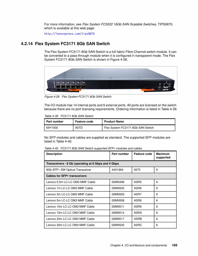
For more information, see Flex System FC5022 16Gb SAN Scalable Switches, TIPS0870, which is available at this web page:
http://lenovopress.com/tips0870
4.2.14 Flex System FC3171 8Gb SAN Switch
The Flex System FC3171 8Gb SAN Switch is a full-fabric Fibre Channel switch module. It can be converted to a pass-through module when it is configured in transparent mode. The Flex System FC3171 8Gb SAN Switch is shown in Figure 4-28.
Figure 4-28 Flex System FC3171 8Gb SAN Switch
The I/O module has 14 internal ports and 6 external ports. All ports are licensed on the switch because there are no port licensing requirements. Ordering information is listed in Table 4-39.
Table 4-39 FC3171 8Gb SAN Switch
No SFP modules and cables are supplied as standard. The supported SFP modules are listed in Table 4-40.
Table 4-40 FC3171 8Gb SAN Switch supported SFP+ modules and cables
Part number Feature code Product Name
69Y1930 A0TD Flex System FC3171 8Gb SAN Switch
Description Part number Feature code Maximum supported
Transceivers - 8 Gb (operating at 8 Gbps and 4 Gbps
8Gb SFP+ SW Optical Transceiver 44X1964 5075 6
Cables for SFP+ transceivers
Lenovo 0.5m LC-LC OM3 MMF Cable 00MN499 ASR5 6
Lenovo 1m LC-LC OM3 MMF Cable 00MN502 ASR6 6
Lenovo 3m LC-LC OM3 MMF Cable 00MN505 ASR7 6
Lenovo 5m LC-LC OM3 MMF Cable 00MN508 ASR8 6
Lenovo 10m LC-LC OM3 MMF Cable 00MN511 ASR9 6
Lenovo 15m LC-LC OM3 MMF Cable 00MN514 ASRA 6
Lenovo 25m LC-LC OM3 MMF Cable 00MN517 ASRB 6
Lenovo 30m LC-LC OM3 MMF Cable 00MN520 ASRC 6
Chapter 4. I/O architecture and components 169
You can reconfigure the FC3171 8Gb SAN Switch to become a pass-through module by using the switch GUI or CLI. The module can then be converted back to a full function SAN switch at some future date. The switch requires a reset when you turn on or off transparent mode.
The switch can be configured by using the following methods:
� Command Line
Access the switch by using the console port through the CMM or through the Ethernet port. This method requires a basic understanding of the CLI commands.
� QuickTools
Requires a current version of the Java runtime environment on your workstation before you point a web browser to the switch’s IP address. The IP address of the switch must be configured. QuickTools does not require a license and the code is included.
When in Full Fabric mode, access to all of the Fibre Channel Security features is provided on this switch. Security includes the services of SSL and SSH, which are available. In addition, RADIUS servers can be used for device and user authentication. After SSL or SSH is enabled, the security features are available to be configured. By using the configuring security features, the SAN administrator can configure which devices are allowed to log on to the Full Fabric Switch module. This process is done by creating security sets with security groups. These sets are configured on a per switch basis. The security features are not available when in pass-through mode.
The FC3171 8Gb SAN Switch includes the following specifications and standards:
� Fibre Channel standards:
– C-PH version 4.3– FC-PH-2– FC-PH-3– FC-AL version 4.5– FC-AL-2 Rev 7.0– FC-FLA– FC-GS-3– FC-FG– FC-PLDA– FC-Tape– FC-VI– FC-SW-2– Fibre Channel Element MIB RFC 2837– Fibre Alliance MIB version 4.0
� Fibre Channel protocols:
– Fibre Channel service classes: Class 2 and class 3– Operation modes: Fibre Channel class 2 and class 3, connectionless
� External port type:
– Full fabric mode: Generic loop port– Transparent mode: Transparent fabric port
� Internal port type:
– Full fabric mode: F_port– Transparent mode: Transparent host port/NPIV mode– Support for up to 44 host NPIV logins
170 Lenovo Flex System Products and Technology
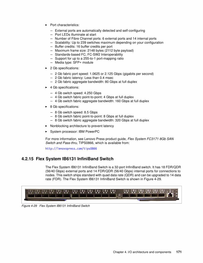
� Port characteristics:
– External ports are automatically detected and self-configuring– Port LEDs illuminate at start– Number of Fibre Channel ports: 6 external ports and 14 internal ports– Scalability: Up to 239 switches maximum depending on your configuration– Buffer credits: 16 buffer credits per port– Maximum frame size: 2148 bytes (2112 byte payload)– Standards-based FC, FC-SW2 Interoperability– Support for up to a 255-to-1 port-mapping ratio– Media type: SFP+ module
� 2 Gb specifications:
– 2 Gb fabric port speed: 1.0625 or 2.125 Gbps (gigabits per second)– 2 Gb fabric latency: Less than 0.4 msec– 2 Gb fabric aggregate bandwidth: 80 Gbps at full duplex
� 4 Gb specifications:
– 4 Gb switch speed: 4.250 Gbps– 4 Gb switch fabric point-to-point: 4 Gbps at full duplex– 4 Gb switch fabric aggregate bandwidth: 160 Gbps at full duplex
� 8 Gb specifications:
– 8 Gb switch speed: 8.5 Gbps– 8 Gb switch fabric point-to-point: 8 Gbps at full duplex– 8 Gb switch fabric aggregate bandwidth: 320 Gbps at full duplex
� Nonblocking architecture to prevent latency
� System processor: IBM PowerPC
For more information, see Lenovo Press product guide, Flex System FC3171 8Gb SAN Switch and Pass-thru, TIPS0866, which is available from:
http://lenovopress.com/tips0866
4.2.15 Flex System IB6131 InfiniBand Switch
The Flex System IB6131 InfiniBand Switch is a 32-port InfiniBand switch. It has 18 FDR/QDR (56/40 Gbps) external ports and 14 FDR/QDR (56/40 Gbps) internal ports for connections to nodes. This switch ships standard with quad data rate (QDR) and can be upgraded to 14 data rate (FDR). The Flex System IB6131 InfiniBand Switch is shown in Figure 4-29.
Figure 4-29 Flex System IB6131 InfiniBand Switch
Chapter 4. I/O architecture and components 171
The part numbers and feature codes for the switches are listed in Table 4-41.
Table 4-41 Flex System IB6131 InfiniBand Switch Part number and upgrade option
Running the MLNX-OS, this switch has one external 1 Gb management port and a mini USB Serial port for updating software and debug use. These ports are in addition to InfiniBand internal and external ports.
The switch has 14 internal QDR links and 18 CX4 uplink ports. All ports are enabled. The switch can be upgraded to FDR speed (56 Gbps) by using the FoD process with part number 90Y3462, as listed in Table 4-41.
No InfiniBand cables are shipped as standard with this switch. These cables must be purchased separately.
Supported cables are listed in Table 4-42.
Table 4-42 IB6131 InfiniBand Switch InfiniBand supported cables
The switch includes the following specifications:
� IBTA 1.3 and 1.21 compliance
� Congestion control
� Adaptive routing
� Port mirroring
� Auto-Negotiation of 10 Gbps, 20 Gbps, 40 Gbps, or 56 Gbps
� Measured node-to-node latency of less than 170 nanoseconds
� Mellanox QoS: Nine InfiniBand virtual lanes for all ports, eight data transport lanes, and one management lane
� High switching performance: Simultaneous wire-speed any port to any port
� Addressing: 48K Unicast Addresses max per subnet, 16K multicast addresses per subnet
� Switch throughput capability of 1.8 Tb/s
For more information, see Lenovo Press product guide, Flex System IB6131 InfiniBand Switch, TIPS0871, which is available from:
http://lenovopress.com/tips0871
Part number Feature codes Product Name
90Y3450 A1EK Flex System IB6131 InfiniBand Switch:� 18 external QDR ports� 14 QDR internal ports
90Y3462 A1QX Flex System IB6131 InfiniBand Switch (FDR Upgrade): upgrades all ports to FDR speeds
Part number Feature code Description
90Y3470 A227 3m FDR InfiniBand Cable (passive)
172 Lenovo Flex System Products and Technology
4.3 I/O adapters
Each compute node has the optional capability of accommodating one or more I/O adapters to provide connections to the chassis switch modules. The routing of the I/O adapters ports is done through the chassis midplane to the I/O modules. The I/O adapters allow the compute nodes to connect to different LAN or SAN fabric types through the switch modules or pass-through modules in the chassis.
Any supported I/O adapter can be installed in any available I/O connector. On servers with the embedded 10 Gb Ethernet controller, the LOM connector must be unscrewed and removed. After it is installed, the I/O adapter on I/O connector 1 is routed to I/O module bay 1 and bay 2 of the chassis. The I/O adapter that is installed on I/O connector 2 is routed to I/O module bay 3 and bay 4 of the chassis.
For more information about specific port routing information, see 4.1, “I/O architecture” on page 94.
This section includes the following topics:
� 4.3.1, “Form factor” on page 174� 4.3.2, “Naming structure” on page 174� 4.3.3, “Supported compute nodes” on page 175� 4.3.4, “Comparing the Ethernet adapters” on page 176� 4.3.5, “Flex System EN2024 4-port 1Gb Ethernet Adapter” on page 177� 4.3.6, “Flex System EN4132 2-port 10Gb Ethernet Adapter” on page 179� 4.3.7, “Flex System EN6132 2-port 40Gb Ethernet Adapter” on page 180� 4.3.8, “Flex System CN4022 2-port 10Gb Converged Adapter” on page 181� 4.3.9, “Flex System CN4052S 10Gb VFA5.2 Adapter” on page 184� 4.3.10, “Flex System CN4054S 10Gb VFA5.2 Adapter” on page 188� 4.3.11, “Flex System EN4172 2-port 10Gb Ethernet Adapter” on page 191� 4.3.12, “Flex System CN4058S 10Gb Virtual Fabric Adapters” on page 193� 4.3.13, “Flex System FC3172 2-port 8Gb FC Adapter” on page 197� 4.3.14, “Flex System FC3052 2-port 8Gb FC Adapter” on page 198� 4.3.15, “Flex System FC5022 2-port 16Gb FC Adapter” on page 200� 4.3.16, “Flex System FC5052 2-port and FC5054 4-port 16Gb FC adapters” on page 201� 4.3.17, “Flex System FC5172 2-port 16Gb FC Adapter” on page 204� 4.3.18, “Flex System IB6132 2-port FDR InfiniBand Adapter” on page 205
Chapter 4. I/O architecture and components 173
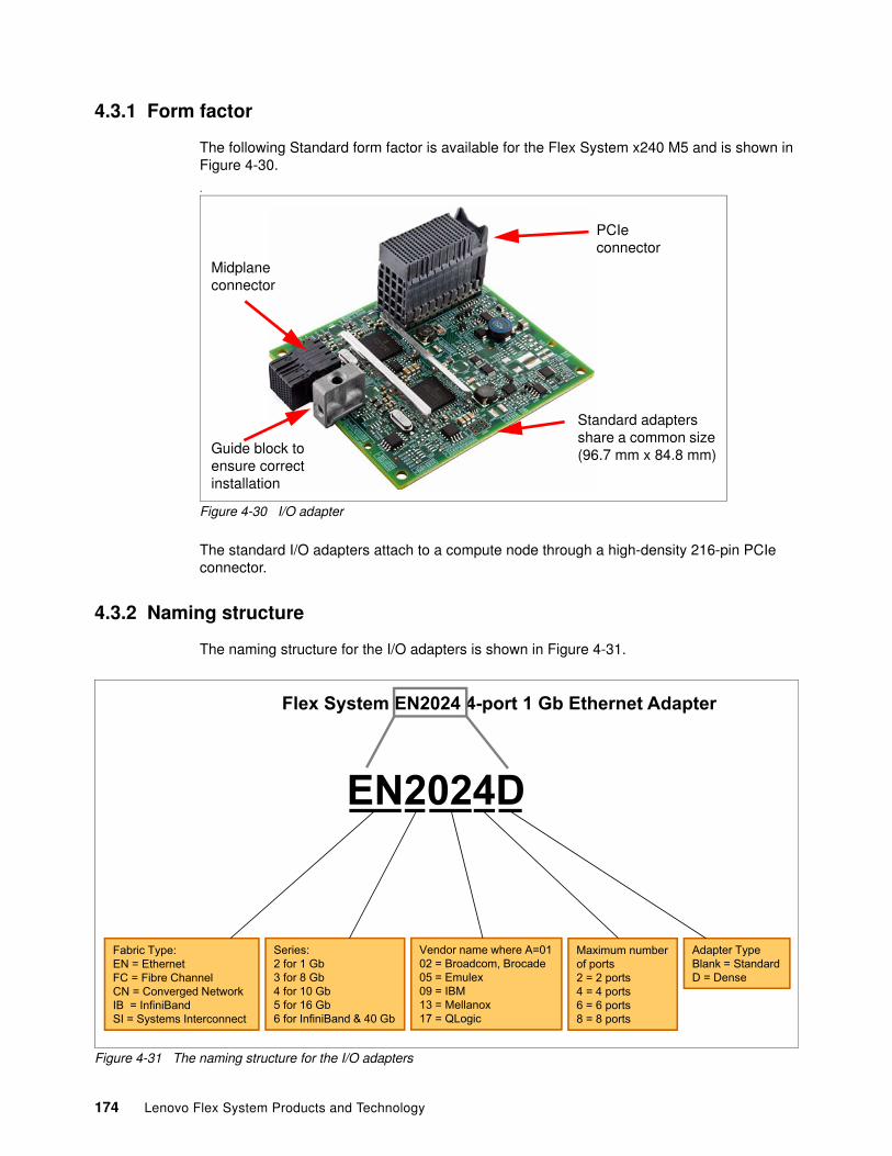
4.3.1 Form factor
The following Standard form factor is available for the Flex System x240 M5 and is shown in Figure 4-30.
.
Figure 4-30 I/O adapter
The standard I/O adapters attach to a compute node through a high-density 216-pin PCIe connector.
4.3.2 Naming structure
The naming structure for the I/O adapters is shown in Figure 4-31.
Figure 4-31 The naming structure for the I/O adapters
PCIe connector
Guide block to ensure correct installation
Midplane connector
Standard adapters share a common size (96.7 mm x 84.8 mm)
�������Flex System EN2024 4-port 1 Gb Ethernet Adapter
EN2024D
Fabric Type: EN = EthernetFC = Fibre ChannelCN = Converged NetworkIB = InfiniBandSI = Systems Interconnect
Series: 2 for 1 Gb3 for 8 Gb4 for 10 Gb5 for 16 Gb6 for InfiniBand & 40 Gb
Vendor name where A=0102 = Broadcom, Brocade05 = Emulex09 = IBM13 = Mellanox17 = QLogic
Maximum numberof ports 2 = 2 ports4 = 4 ports6 = 6 ports8 = 8 ports
Adapter TypeBlank = Standard D = Dense
174 Lenovo Flex System Products and Technology
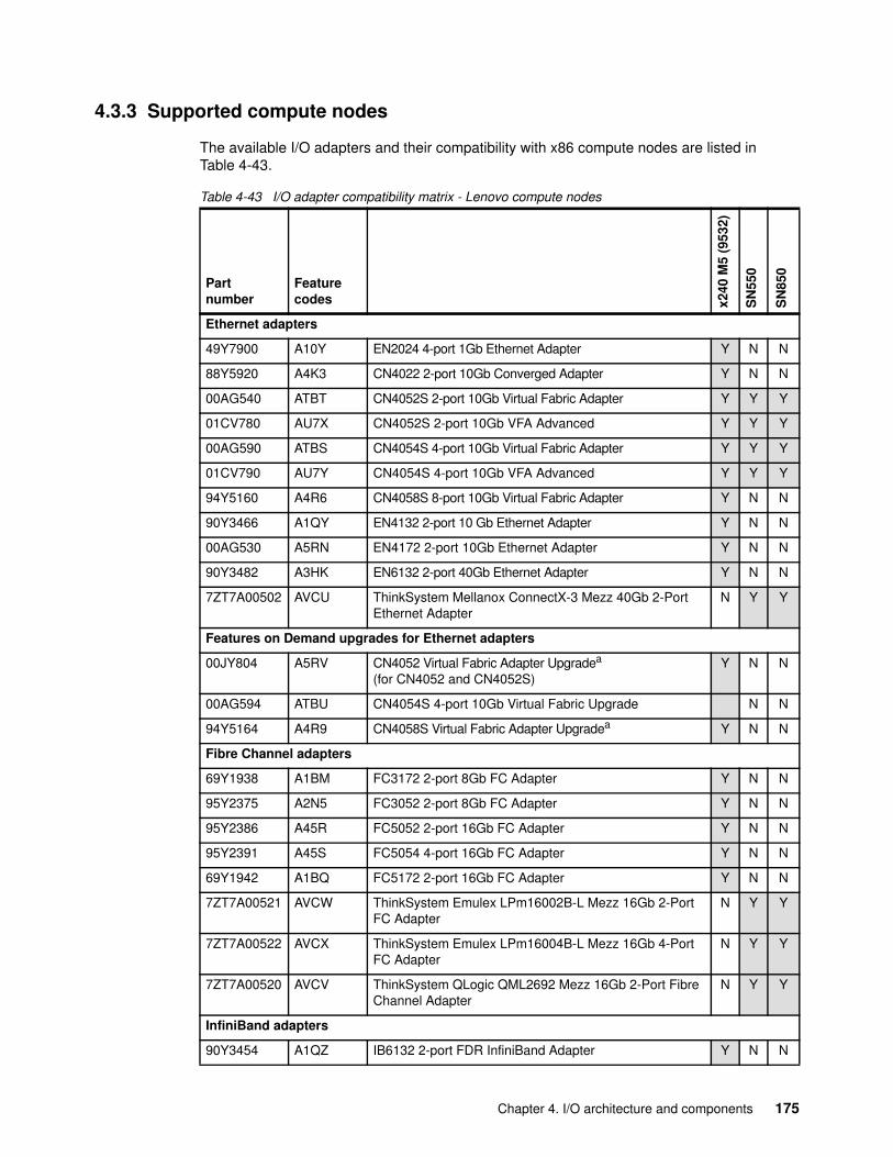
4.3.3 Supported compute nodes
The available I/O adapters and their compatibility with x86 compute nodes are listed in Table 4-43.
Table 4-43 I/O adapter compatibility matrix - Lenovo compute nodes
Partnumber
Featurecodes x2
40 M
5 (9
532)
SN
550
SN
850
Ethernet adapters
49Y7900 A10Y EN2024 4-port 1Gb Ethernet Adapter Y N N
88Y5920 A4K3 CN4022 2-port 10Gb Converged Adapter Y N N
00AG540 ATBT CN4052S 2-port 10Gb Virtual Fabric Adapter Y Y Y
01CV780 AU7X CN4052S 2-port 10Gb VFA Advanced Y Y Y
00AG590 ATBS CN4054S 4-port 10Gb Virtual Fabric Adapter Y Y Y
01CV790 AU7Y CN4054S 4-port 10Gb VFA Advanced Y Y Y
94Y5160 A4R6 CN4058S 8-port 10Gb Virtual Fabric Adapter Y N N
90Y3466 A1QY EN4132 2-port 10 Gb Ethernet Adapter Y N N
00AG530 A5RN EN4172 2-port 10Gb Ethernet Adapter Y N N
90Y3482 A3HK EN6132 2-port 40Gb Ethernet Adapter Y N N
7ZT7A00502 AVCU ThinkSystem Mellanox ConnectX-3 Mezz 40Gb 2-Port Ethernet Adapter
N Y Y
Features on Demand upgrades for Ethernet adapters
00JY804 A5RV CN4052 Virtual Fabric Adapter Upgradea
(for CN4052 and CN4052S)Y N N
00AG594 ATBU CN4054S 4-port 10Gb Virtual Fabric Upgrade N N
94Y5164 A4R9 CN4058S Virtual Fabric Adapter Upgradea Y N N
Fibre Channel adapters
69Y1938 A1BM FC3172 2-port 8Gb FC Adapter Y N N
95Y2375 A2N5 FC3052 2-port 8Gb FC Adapter Y N N
95Y2386 A45R FC5052 2-port 16Gb FC Adapter Y N N
95Y2391 A45S FC5054 4-port 16Gb FC Adapter Y N N
69Y1942 A1BQ FC5172 2-port 16Gb FC Adapter Y N N
7ZT7A00521 AVCW ThinkSystem Emulex LPm16002B-L Mezz 16Gb 2-Port FC Adapter
N Y Y
7ZT7A00522 AVCX ThinkSystem Emulex LPm16004B-L Mezz 16Gb 4-Port FC Adapter
N Y Y
7ZT7A00520 AVCV ThinkSystem QLogic QML2692 Mezz 16Gb 2-Port Fibre Channel Adapter
N Y Y
InfiniBand adapters
90Y3454 A1QZ IB6132 2-port FDR InfiniBand Adapter Y N N
Chapter 4. I/O architecture and components 175
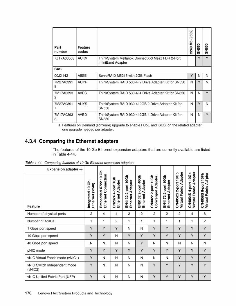
4.3.4 Comparing the Ethernet adapters
The features of the 10 Gb Ethernet expansion adapters that are currently available are listed in Table 4-44.
Table 4-44 Comparing features of 10 Gb Ethernet expansion adapters
7ZT7A00508 AUKV ThinkSystem Mellanox ConnectX-3 Mezz FDR 2-Port InfiniBand Adapter
Y Y
SAS
00JX142 A5SE ServeRAID M5215 with 2GB Flash Y N N
7M27A03918
AUYR ThinkSystem RAID 530-4i 2 Drive Adapter Kit for SN550 N Y N
7M17A03932
AVEC ThinkSystem RAID 530-4i 4 Drive Adapter Kit for SN850 N N Y
7M27A03917
AUYS ThinkSystem RAID 930-4i-2GB 2 Drive Adapter Kit for SN550
N Y N
7M17A03933
AVED ThinkSystem RAID 930-4i-2GB 4 Drive Adapter Kit for SN850
N N Y
a. Features on Demand (software) upgrade to enable FCoE and iSCSI on the related adapter; one upgrade needed per adapter.
Partnumber
Featurecodes x2
40 M
5 (9
532)
SN
550
SN
850
Expansion adapter →
Inte
gra
ted
10
Gb
E
ther
net
(x2
40)
Em
bed
ded
X72
2 10
Gb
E
ther
net
Co
nn
ecti
on
EN
2024
4-p
ort
1G
b
Eth
ern
et A
dap
ter
EN
4132
2-p
ort
10G
b
Eth
ern
et A
dap
ter
EN
6132
2-p
ort
40G
b
Eth
ern
et A
dap
ter
CN
4022
2-p
ort
10G
b
Co
nve
rged
Ad
apte
r
EN
4172
2-p
ort
10G
b
Eth
ern
et A
dap
ter
CN
4052
S 2
-po
rt 1
0Gb
V
irtu
al F
abri
c A
dap
ter
CN
4054
S 4
-po
rt 1
0Gb
V
irtu
al F
abri
c A
dap
ter
CN
4058
S 8
-po
rt 1
0Fb
V
irtu
al F
abri
c A
d`p
ter
Feature
Number of physical ports 2 4 4 2 2 2 2 2 4 8
Number of ASICs 1 1 2 1 1 1 1 1 1 2
1 Gbps port speed Y Y Y N N Y Y Y Y Y
10 Gbps port speed Y Y N Y Y Y Y Y Y Y
40 Gbps port speed N N N N Y N N N N N
pNIC mode Y Y Y Y Y Y Y Y Y Y
vNIC Virtual Fabric mode (vNIC1) Y N N N N N N Y Y Y
vNIC Switch Independent mode (vNIC2)
Y N N N N Y Y Y Y Y
vNIC Unified Fabric Port (UFP) Y N N N N Y Y Y Y Y
176 Lenovo Flex System Products and Technology
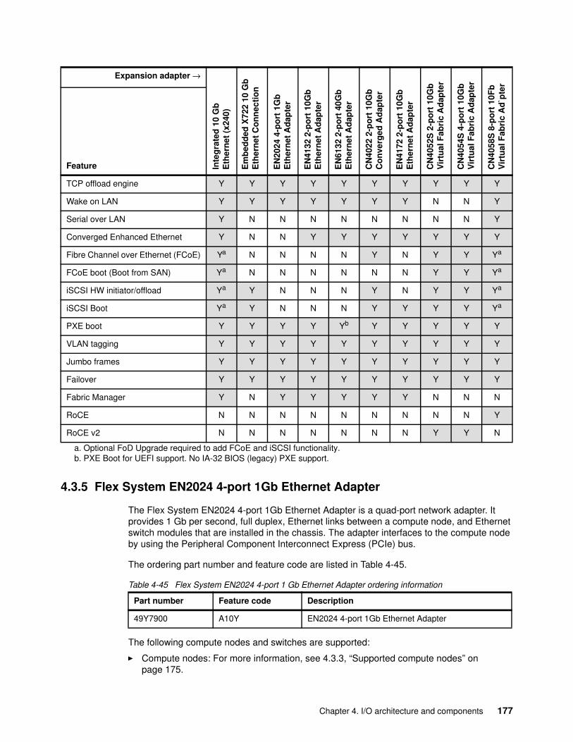
4.3.5 Flex System EN2024 4-port 1Gb Ethernet Adapter
The Flex System EN2024 4-port 1Gb Ethernet Adapter is a quad-port network adapter. It provides 1 Gb per second, full duplex, Ethernet links between a compute node, and Ethernet switch modules that are installed in the chassis. The adapter interfaces to the compute node by using the Peripheral Component Interconnect Express (PCIe) bus.
The ordering part number and feature code are listed in Table 4-45.
Table 4-45 Flex System EN2024 4-port 1 Gb Ethernet Adapter ordering information
The following compute nodes and switches are supported:
� Compute nodes: For more information, see 4.3.3, “Supported compute nodes” on page 175.
TCP offload engine Y Y Y Y Y Y Y Y Y Y
Wake on LAN Y Y Y Y Y Y Y N N Y
Serial over LAN Y N N N N N N N N Y
Converged Enhanced Ethernet Y N N Y Y Y Y Y Y Y
Fibre Channel over Ethernet (FCoE) Ya N N N N Y N Y Y Ya
FCoE boot (Boot from SAN) Ya N N N N N N Y Y Ya
iSCSI HW initiator/offload Ya Y N N N Y N Y Y Ya
iSCSI Boot Ya Y N N N Y Y Y Y Ya
PXE boot Y Y Y Y Yb Y Y Y Y Y
VLAN tagging Y Y Y Y Y Y Y Y Y Y
Jumbo frames Y Y Y Y Y Y Y Y Y Y
Failover Y Y Y Y Y Y Y Y Y Y
Fabric Manager Y N Y Y Y Y Y N N N
RoCE N N N N N N N N N Y
RoCE v2 N N N N N N N Y Y N
a. Optional FoD Upgrade required to add FCoE and iSCSI functionality.b. PXE Boot for UEFI support. No IA-32 BIOS (legacy) PXE support.
Expansion adapter →
Inte
gra
ted
10
Gb
E
ther
net
(x2
40)
Em
bed
ded
X72
2 10
Gb
E
ther
net
Co
nn
ecti
on
EN
2024
4-p
ort
1G
b
Eth
ern
et A
dap
ter
EN
4132
2-p
ort
10G
b
Eth
ern
et A
dap
ter
EN
6132
2-p
ort
40G
b
Eth
ern
et A
dap
ter
CN
4022
2-p
ort
10G
b
Co
nve
rged
Ad
apte
r
EN
4172
2-p
ort
10G
b
Eth
ern
et A
dap
ter
CN
4052
S 2
-po
rt 1
0Gb
V
irtu
al F
abri
c A
dap
ter
CN
4054
S 4
-po
rt 1
0Gb
V
irtu
al F
abri
c A
dap
ter
CN
4058
S 8
-po
rt 1
0Fb
V
irtu
al F
abri
c A
d`p
ter
Feature
Part number Feature code Description
49Y7900 A10Y EN2024 4-port 1Gb Ethernet Adapter
Chapter 4. I/O architecture and components 177
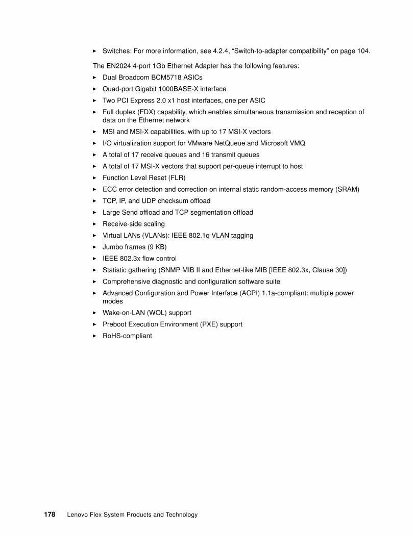
� Switches: For more information, see 4.2.4, “Switch-to-adapter compatibility” on page 104.
The EN2024 4-port 1Gb Ethernet Adapter has the following features:
� Dual Broadcom BCM5718 ASICs
� Quad-port Gigabit 1000BASE-X interface
� Two PCI Express 2.0 x1 host interfaces, one per ASIC
� Full duplex (FDX) capability, which enables simultaneous transmission and reception of data on the Ethernet network
� MSI and MSI-X capabilities, with up to 17 MSI-X vectors
� I/O virtualization support for VMware NetQueue and Microsoft VMQ
� A total of 17 receive queues and 16 transmit queues
� A total of 17 MSI-X vectors that support per-queue interrupt to host
� Function Level Reset (FLR)
� ECC error detection and correction on internal static random-access memory (SRAM)
� TCP, IP, and UDP checksum offload
� Large Send offload and TCP segmentation offload
� Receive-side scaling
� Virtual LANs (VLANs): IEEE 802.1q VLAN tagging
� Jumbo frames (9 KB)
� IEEE 802.3x flow control
� Statistic gathering (SNMP MIB II and Ethernet-like MIB [IEEE 802.3x, Clause 30])
� Comprehensive diagnostic and configuration software suite
� Advanced Configuration and Power Interface (ACPI) 1.1a-compliant: multiple power modes
� Wake-on-LAN (WOL) support
� Preboot Execution Environment (PXE) support
� RoHS-compliant
178 Lenovo Flex System Products and Technology
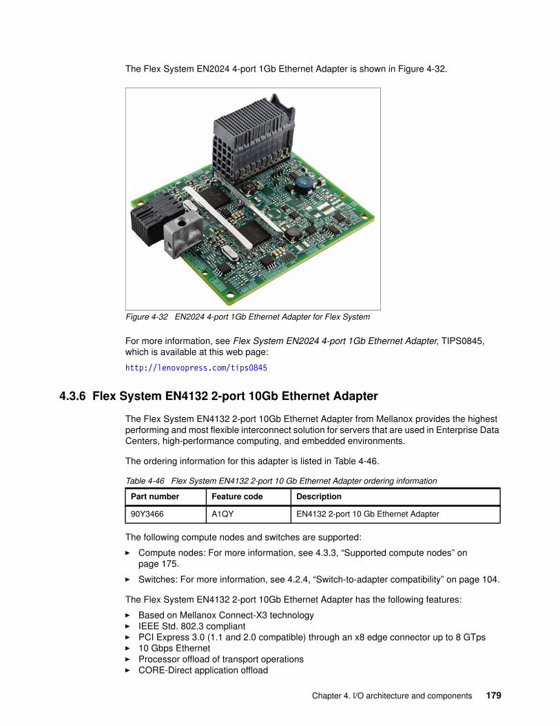
The Flex System EN2024 4-port 1Gb Ethernet Adapter is shown in Figure 4-32.
Figure 4-32 EN2024 4-port 1Gb Ethernet Adapter for Flex System
For more information, see Flex System EN2024 4-port 1Gb Ethernet Adapter, TIPS0845, which is available at this web page:
http://lenovopress.com/tips0845
4.3.6 Flex System EN4132 2-port 10Gb Ethernet Adapter
The Flex System EN4132 2-port 10Gb Ethernet Adapter from Mellanox provides the highest performing and most flexible interconnect solution for servers that are used in Enterprise Data Centers, high-performance computing, and embedded environments.
The ordering information for this adapter is listed in Table 4-46.
Table 4-46 Flex System EN4132 2-port 10 Gb Ethernet Adapter ordering information
The following compute nodes and switches are supported:
� Compute nodes: For more information, see 4.3.3, “Supported compute nodes” on page 175.
� Switches: For more information, see 4.2.4, “Switch-to-adapter compatibility” on page 104.
The Flex System EN4132 2-port 10Gb Ethernet Adapter has the following features:
� Based on Mellanox Connect-X3 technology� IEEE Std. 802.3 compliant� PCI Express 3.0 (1.1 and 2.0 compatible) through an x8 edge connector up to 8 GTps� 10 Gbps Ethernet� Processor offload of transport operations� CORE-Direct application offload
Part number Feature code Description
90Y3466 A1QY EN4132 2-port 10 Gb Ethernet Adapter
Chapter 4. I/O architecture and components 179
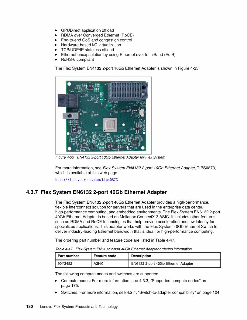
� GPUDirect application offload� RDMA over Converged Ethernet (RoCE)� End-to-end QoS and congestion control� Hardware-based I/O virtualization� TCP/UDP/IP stateless offload� Ethernet encapsulation by using Ethernet over InfiniBand (EoIB)� RoHS-6 compliant
The Flex System EN4132 2-port 10Gb Ethernet Adapter is shown in Figure 4-33.
Figure 4-33 EN4132 2-port 10Gb Ethernet Adapter for Flex System
For more information, see Flex System EN4132 2-port 10Gb Ethernet Adapter, TIPS0873, which is available at this web page:
http://lenovopress.com/tips0873
4.3.7 Flex System EN6132 2-port 40Gb Ethernet Adapter
The Flex System EN6132 2-port 40Gb Ethernet Adapter provides a high-performance, flexible interconnect solution for servers that are used in the enterprise data center, high-performance computing, and embedded environments. The Flex System EN6132 2-port 40Gb Ethernet Adapter is based on Mellanox ConnectX-3 ASIC. It includes other features, such as RDMA and RoCE technologies that help provide acceleration and low latency for specialized applications. This adapter works with the Flex System 40Gb Ethernet Switch to deliver industry-leading Ethernet bandwidth that is ideal for high-performance computing.
The ordering part number and feature code are listed in Table 4-47.
Table 4-47 Flex System EN6132 2-port 40Gb Ethernet Adapter ordering information
The following compute nodes and switches are supported:
� Compute nodes: For more information, see 4.3.3, “Supported compute nodes” on page 175.
� Switches: For more information, see 4.2.4, “Switch-to-adapter compatibility” on page 104.
Part number Feature code Description
90Y3482 A3HK EN6132 2-port 40Gb Ethernet Adapter
180 Lenovo Flex System Products and Technology
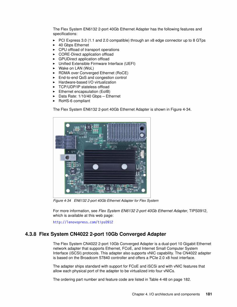
The Flex System EN6132 2-port 40Gb Ethernet Adapter has the following features and specifications:
� PCI Express 3.0 (1.1 and 2.0 compatible) through an x8 edge connector up to 8 GTps� 40 Gbps Ethernet� CPU offload of transport operations� CORE-Direct application offload� GPUDirect application offload� Unified Extensible Firmware Interface (UEFI)� Wake on LAN (WoL)� RDMA over Converged Ethernet (RoCE)� End-to-end QoS and congestion control� Hardware-based I/O virtualization� TCP/UDP/IP stateless offload� Ethernet encapsulation (EoIB)� Data Rate: 1/10/40 Gbps – Ethernet� RoHS-6 compliant
The Flex System EN6132 2-port 40Gb Ethernet Adapter is shown in Figure 4-34.
Figure 4-34 EN6132 2-port 40Gb Ethernet Adapter for Flex System
For more information, see Flex System EN6132 2-port 40Gb Ethernet Adapter, TIPS0912, which is available at this web page:
http://lenovopress.com/tips0912
4.3.8 Flex System CN4022 2-port 10Gb Converged Adapter
The Flex System CN4022 2-port 10Gb Converged Adapter is a dual-port 10 Gigabit Ethernet network adapter that supports Ethernet, FCoE, and Internet Small Computer System Interface (iSCSI) protocols. This adapter also supports vNIC capability. The CN4022 adapter is based on the Broadcom 57840 controller and offers a PCIe 2.0 x8 host interface.
The adapter ships standard with support for FCoE and iSCSi and with vNIC features that allow each physical port of the adapter to be virtualized into four vNICs.
The ordering part number and feature code are listed in Table 4-48 on page 182.
Chapter 4. I/O architecture and components 181
Table 4-48 Flex System CN4022 ordering information.
The following compute nodes and switches are supported:
� Compute nodes: For more information, see 4.3.3, “Supported compute nodes” on page 175.
� Switches: For more information, see 4.2.4, “Switch-to-adapter compatibility” on page 104.
The Flex System CN4022 2-port Converged Adapter has the following features and specification:
� One Broadcom BCM57840 ASIC
� Connection to 1 Gb or 10 Gb data center infrastructure (1 Gb and 10 Gb auto-negotiation)
� PCI Express 2.0 x8 host interface
� Full line-rate performance
� Supports 10 Gb Ethernet, FCoE, and iSCSI
� Ethernet features:
– Ethernet frame: 1500 byte or 9600 byte (jumbo frame)
– VLAN support with VLAN tagging
– vNIC support:
• Supports Switch Independent Mode (vNIC2 mode)
• UFP mode support
• Four vNIC/NPAR Ethernet devices per 10Gb physical port
• Support for two iSCSI ports or for one iSCSI port and one FCoE port, per 10 Gb physical port
– Stateless offload:
• IP, TCP, and UDP checksum offloads• IPv4 and IPv6 offloads• Large send offload (LSO)
– Performance optimization:
• Receive Side Scaling (RSS)• Transmit Side Scaling (TSS)• MSI and MSI-X support• RX/TX multiqueue• TCP offload Engine (TOE) support
– SR-IOV-ready
– Wake on LAN
– Preboot eXecution Environment (PXE) support
– Network teaming, failover, and load balancing:
• Smart Load Balancing (SLB)• Link Aggregation Control Protocol (LACP) and generic trunking
– Management by using Broadcom Advanced Control Suite management application
Part number Feature code Description
88Y5920 A4K3 Flex System CN4022 2-port 10Gb Converged Adapter
182 Lenovo Flex System Products and Technology
– Compliance:
• IEEE 802.3ae (10 Gb Ethernet)• IEEE 802.3ad (Link aggregation)• IEEE 802.3ap Clause73 1G/10G Autonegotiation for 10GBase-KR channels• IEEE 802.1q (VLAN)• IEEE 802.1p (Priority Encoding)• IEEE 802.3x (Flow Control)• IEEE 802.1au (Congestion Notification)• IPv4 (RFQ 791)• IPv6 (RFC 2460)• IEEE 1588/802.1as Precision Time Protocol (PTP)• IEEE 802.1Qbb PFC• IEEE 802.1Qaz ETS• IEEE 802.1Qaz DCBX Protocol
� iSCSI specifications:
– iSCSI initiator hardware offload and boot support
– Protocols:
• RFC 3347 (iSCSI Requirements and Design Considerations)• Challenge Handshake Authentication Protocol (CHAP)• iSNS• Service Location Protocol (SLP)
� FCoE features:
– A total of 3,500 N_Port ID Virtualization (NPIV) interfaces (total for adapter)– Support for FIP and FCoE Ethertypes– Fabric Provided MAC Addressing (FPMA) support– 2,048 concurrent port logins (RPIs) per port– 1,024 active exchanges (XRIs) per port
Notes: Consider the following points:
� FCoE is not supported by Red Hat Enterprise Linux KVM.� FCoE support for VLAN discovery only with the port PVID = 1.� FCoE SAN boot is not supported.
Chapter 4. I/O architecture and components 183
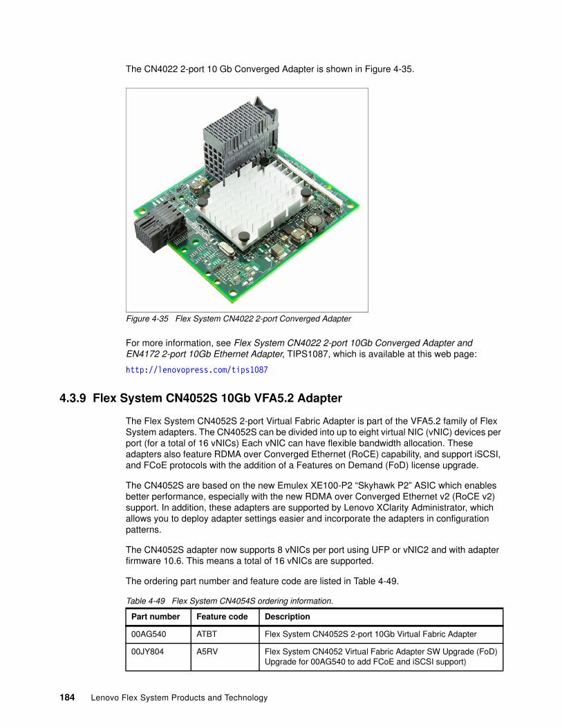
The CN4022 2-port 10 Gb Converged Adapter is shown in Figure 4-35.
Figure 4-35 Flex System CN4022 2-port Converged Adapter
For more information, see Flex System CN4022 2-port 10Gb Converged Adapter and EN4172 2-port 10Gb Ethernet Adapter, TIPS1087, which is available at this web page:
http://lenovopress.com/tips1087
4.3.9 Flex System CN4052S 10Gb VFA5.2 Adapter
The Flex System CN4052S 2-port Virtual Fabric Adapter is part of the VFA5.2 family of Flex System adapters. The CN4052S can be divided into up to eight virtual NIC (vNIC) devices per port (for a total of 16 vNICs) Each vNIC can have flexible bandwidth allocation. These adapters also feature RDMA over Converged Ethernet (RoCE) capability, and support iSCSI, and FCoE protocols with the addition of a Features on Demand (FoD) license upgrade.
The CN4052S are based on the new Emulex XE100-P2 “Skyhawk P2” ASIC which enables better performance, especially with the new RDMA over Converged Ethernet v2 (RoCE v2) support. In addition, these adapters are supported by Lenovo XClarity Administrator, which allows you to deploy adapter settings easier and incorporate the adapters in configuration patterns.
The CN4052S adapter now supports 8 vNICs per port using UFP or vNIC2 and with adapter firmware 10.6. This means a total of 16 vNICs are supported.
The ordering part number and feature code are listed in Table 4-49.
Table 4-49 Flex System CN4054S ordering information.
Part number Feature code Description
00AG540 ATBT Flex System CN4052S 2-port 10Gb Virtual Fabric Adapter
00JY804 A5RV Flex System CN4052 Virtual Fabric Adapter SW Upgrade (FoD)Upgrade for 00AG540 to add FCoE and iSCSI support)
184 Lenovo Flex System Products and Technology
This adapter offers the following key features:
� Multiprotocol support for 10 GbE � Virtual NIC emulation � Full hardware storage offloads� Lenovo Features on Demand (FoD) � Emulex Virtual Network Acceleration (VNeX) technology support � Advanced RDMA capabilities with RoCE v2 � Lenovo XClarity support
The following compute nodes and switches are supported:
� Compute nodes: For more information, see 4.3.3, “Supported compute nodes” on page 175.
� Switches: For more information, see 4.2.4, “Switch-to-adapter compatibility” on page 104.
The Flex System CN4054S 2-port Virtual Fabric Adapter has the following features and specification:
� Two 10 Gb Ethernet ports� Based on the Emulex XE100-P2 series design - Single XE102-P2 ASIC� PCIe Express 3.0 x8 host interface� Optional support for FCoE and iSCSI (standard on the Advanced adapter option)� vNIC (NIC partition) capability� MSI-X support� Fabric Manager support� Lenovo XClarity Administrator support� Power consumption: 25 W maximum
Virtualization features:
� vNIC partitions with UFP mode - 8 NIC partitions per port, 16 total� vNIC partitions with vNIC2 mode - 8 NIC partitions per port, 16 total� vNIC partitions with vNIC1 mode - 4 NIC partitions per port, 8 total� Complies with PCI-SIG specification for SR-IOV� VXLAN/NVGRE encapsulation and offload� PCI-SIG Address Translation Service (ATS) v1.0� Virtual Switch Port Mirroring for Diagnostic purposes� Virtual Ethernet Bridge (VEB)� 62 Virtual functions (VF)� QoS for controlling & monitoring bandwidth that is assigned to and used by virtual entities� Traffic shaping and QoS across each virtual function (VF) and physical function (PF)� Message Signal Interrupts (MSI-X) support� VMware NetQue / VMQ support� Microsoft VMQ & Dynamic VMQ support in Hyper-V
Ethernet and NIC features:
� NDIS 5.2, 6.0, and 6.2 compliant Ethernet functionality� IPv4/IPv6 TCP, UDP, and Checksum Offload
01CV780 AU7X Flex System CN4052S 2-port 10Gb Virtual Fabric Adapter Advanced (includes FCoE and iSCSI support)
Adapter and Switch Firmware: 8 NIC partitions per port requires adapter firmware 10.6 or later; UFP mode also requires switch firmware 8.3 or later.
Part number Feature code Description
Chapter 4. I/O architecture and components 185
� IPv4/IPv6 TCP, UDP Receive Side Scaling (RSS)� IPv4/IPv6 Large Send Offload (LSO)� Programmable MAC addresses� 128 MAC/vLAN addresses per port� Support for HASH-based broadcast frame filters per port� vLAN insertion and extraction� 9216 byte Jumbo frame support� Receive Side Scaling (RSS)� Filters: MAC and vLAN� PXE Boot support
Remote Direct Memory Access (RDMA):
� Direct data placement in application buffers without processor intervention– Supports RDMA over converged Ethernet (RoCE) specifications – Supports RoCE v2 by replacing RoCE over IP with RoCE over UDP– 20% more RoCE Queue Pairs than VFA5– 16K RoCE Memory Regions (VFA5 offers 8K)
� Linux OpenFabrics Enterprise Distribution (OFED) Support� Low latency queues for small packet sends and receives� Local interprocess communication option by internal VEB switch� TCP/IP Stack By-Pass
Data Center Bridging / Converged Enhanced Ethernet (DCB/CEE):
� Hardware Offloads of Ethernet TCP/IP� 802.1Qbb Priority Flow Control (PFC)� 802.1 Qaz Enhanced Transmission Selection (ETS)� 802.1 Qaz Data Center Bridging Exchange (DCBX)
Fibre Channel over Ethernet (FCoE) offload (optional via a Features on Demand upgrade, standard on the Advanced adapter option):
� Hardware offloads of Ethernet TCP/IP� ANSI T11 FC-BB-5 Support� Programmable Worldwide Name (WWN)� Support for FIP and FCoE Ether Types� Supports up to 255 NPIV Interfaces per port� FCoE Initiator� Common driver for Emulex Universal CNA and Fibre Channel HBAs� 255 N_Port ID Virtualization (NPIV) interfaces per port� Fabric Provided MAC Addressing (FPMA) support� Up to 4096 concurrent port logins (RPIs) per port� Up to 2048 active exchanges (XRIs) per port� FCoE Boot support
iSCSI offload (optional via a Features on Demand upgrade, standard on the Advanced adapter option)
� Full iSCSI Protocol Offload� Header, Data Digest (CRC), and PDU� Direct data placement of SCSI data� 2048 Offloaded iSCSI connections� iSCSI initiator and concurrent initiator /target modes� Multipath I/O� OS-neutral INT13 based iSCSI boot and iSCSI crash memory dump support� RFC 4171 Internet Storage Name Service (iSNS)� iSCSI Boot support
186 Lenovo Flex System Products and Technology
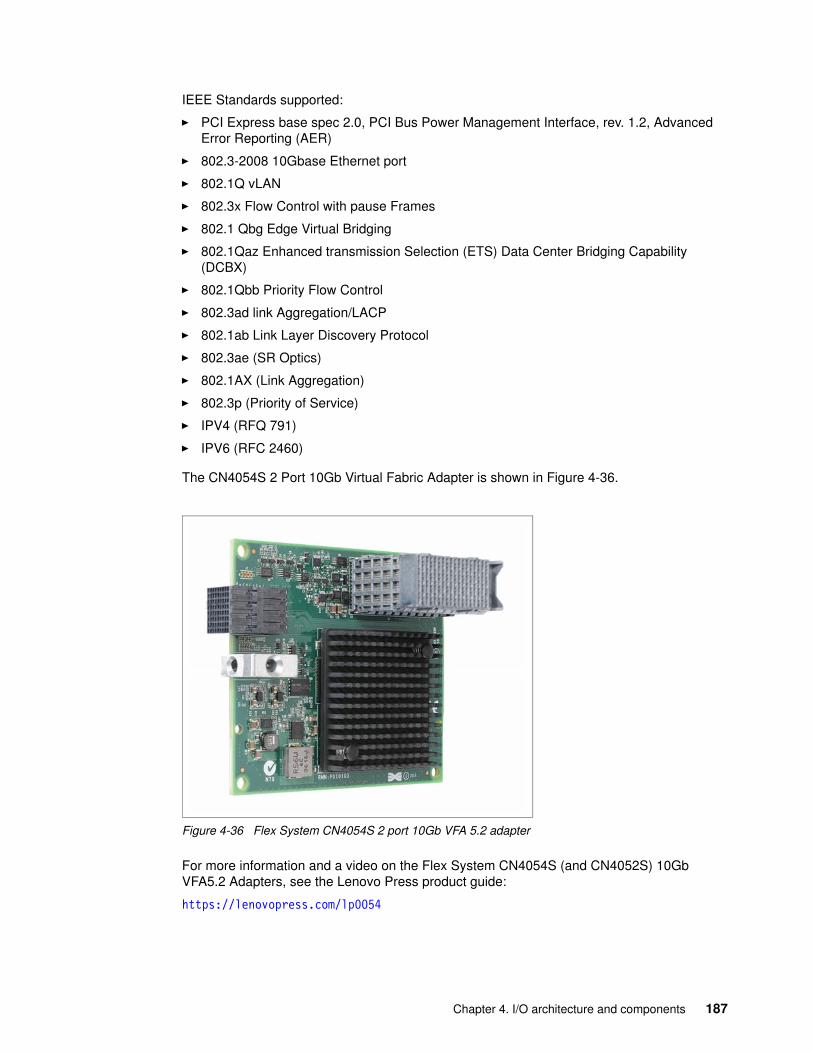
IEEE Standards supported:
� PCI Express base spec 2.0, PCI Bus Power Management Interface, rev. 1.2, Advanced Error Reporting (AER)
� 802.3-2008 10Gbase Ethernet port
� 802.1Q vLAN
� 802.3x Flow Control with pause Frames
� 802.1 Qbg Edge Virtual Bridging
� 802.1Qaz Enhanced transmission Selection (ETS) Data Center Bridging Capability (DCBX)
� 802.1Qbb Priority Flow Control
� 802.3ad link Aggregation/LACP
� 802.1ab Link Layer Discovery Protocol
� 802.3ae (SR Optics)
� 802.1AX (Link Aggregation)
� 802.3p (Priority of Service)
� IPV4 (RFQ 791)
� IPV6 (RFC 2460)
The CN4054S 2 Port 10Gb Virtual Fabric Adapter is shown in Figure 4-36.
Figure 4-36 Flex System CN4054S 2 port 10Gb VFA 5.2 adapter
For more information and a video on the Flex System CN4054S (and CN4052S) 10Gb VFA5.2 Adapters, see the Lenovo Press product guide:
https://lenovopress.com/lp0054
Chapter 4. I/O architecture and components 187
4.3.10 Flex System CN4054S 10Gb VFA5.2 Adapter
The Flex System CN4054S 4-port Virtual Fabric Adapter is part of the VFA5.2 family of Flex System adapters. The CN4054S can be divided in to four vNICs (for a total of 16 vNICs). Each vNIC can have flexible bandwidth allocation. These adapters also feature RDMA over Converged Ethernet (RoCE) capability, and support iSCSI, and FCoE protocols with the addition of a Features on Demand (FoD) license upgrade.
The CN4054S are based on the new Emulex XE100-P2 “Skyhawk P2” ASIC which enables better performance, especially with the new RDMA over Converged Ethernet v2 (RoCE v2) support. In addition, these adapters are supported by Lenovo XClarity Administrator, which allows you to deploy adapter settings easier and incorporate the adapters in configuration patterns.
The ordering part number and feature code is listed in Table 4-50.
Table 4-50 Flex System CN4054S ordering information.
This adapter offers the following key features:
� Multiprotocol support for 10 GbE � Virtual NIC emulation � Full hardware storage offloads� Lenovo Features on Demand (FoD) � Emulex Virtual Network Acceleration (VNeX) technology support � Advanced RDMA capabilities with RoCE v2 � Lenovo XClarity support
The following compute nodes and switches are supported:
� Compute nodes: For more information, see 4.3.3, “Supported compute nodes” on page 175.
� Switches: For more information, see 4.2.4, “Switch-to-adapter compatibility” on page 104.
The Flex System CN4054S 4-port Virtual Fabric Adapter has the following features and specification:
� Four 10 Gb Ethernet ports� Based on the Emulex XE100-P2 series design - Single XE104-P2 ASIC� PCIe Express 3.0 x8 host interface� Optional support for FCoE and iSCSI (standard on the Advanced adapter option)� vNIC (NIC partition) capability� MSI-X support� Fabric Manager support� Lenovo XClarity Administrator support� Power consumption: 25 W maximum
Virtualization features:
Partnumber
Feature codeDescription
00AG590 ATBS Flex System CN4054S 4-port 10Gb Virtual Fabric Adapter
00AG594 ATBU Flex System CN4054S 4-port 10Gb Virtual Fabric Adapter SW Upgrade (adds FCoE and iSCSI support for 00AG590)
01CV790 AU7Y Flex System CN4054S 4-port 10Gb Virtual Fabric Adapter Advanced (includes FCoE and iSCSI support)
188 Lenovo Flex System Products and Technology
� vNIC partitions with UFP mode - 4NIC partitions per port, 16 total� vNIC partitions with vNIC2 mode - 4NIC partitions per port, 16 total� vNIC partitions with vNIC1 mode - 4 NIC partitions per port, 16 total� Complies with PCI-SIG specification for SR-IOV� VXLAN/NVGRE encapsulation and offload� PCI-SIG Address Translation Service (ATS) v1.0� Virtual Switch Port Mirroring for Diagnostic purposes� Virtual Ethernet Bridge (VEB)� 62 Virtual functions (VF)� QoS for controlling & monitoring bandwidth that is assigned to and used by virtual entities� Traffic shaping and QoS across each virtual function (VF) and physical function (PF)� Message Signal Interrupts (MSI-X) support� VMware NetQue / VMQ support� Microsoft VMQ & Dynamic VMQ support in Hyper-V
Ethernet and NIC features:
� NDIS 5.2, 6.0, and 6.2 compliant Ethernet functionality� IPv4/IPv6 TCP, UDP, and Checksum Offload� IPv4/IPv6 TCP, UDP Receive Side Scaling (RSS)� IPv4/IPv6 Large Send Offload (LSO)� Programmable MAC addresses� 128 MAC/vLAN addresses per port� Support for HASH-based broadcast frame filters per port� vLAN insertion and extraction� 9216 byte Jumbo frame support� Receive Side Scaling (RSS)� Filters: MAC and vLAN� PXE Boot support
Remote Direct Memory Access (RDMA):
� Direct data placement in application buffers without processor intervention– Supports RDMA over converged Ethernet (RoCE) specifications – Supports RoCE v2 by replacing RoCE over IP with RoCE over UDP– 20% more RoCE Queue Pairs than VFA5– 16K RoCE Memory Regions (VFA5 offers 8K)
� Linux Opens Fabrics Enterprise Distribution (OFED) Support� Low latency queues for small packet sends and receives� Local interprocess communication option by internal VEB switch� TCP/IP Stack By-Pass
Data Center Bridging / Converged Enhanced Ethernet (DCB/CEE):
� Hardware Offloads of Ethernet TCP/IP� 802.1Qbb Priority Flow Control (PFC)� 802.1 Qaz Enhanced Transmission Selection (ETS)� 802.1 Qaz Data Center Bridging Exchange (DCBX)
Fibre Channel over Ethernet (FCoE) offload (optional via a Features on Demand upgrade, standard on the Advanced adapter option):
� Hardware offloads of Ethernet TCP/IP� ANSI T11 FC-BB-5 Support� Programmable Worldwide Name (WWN)� Support for FIP and FCoE Ether Types� Supports up to 255 NPIV Interfaces per port� FCoE Initiator
Chapter 4. I/O architecture and components 189
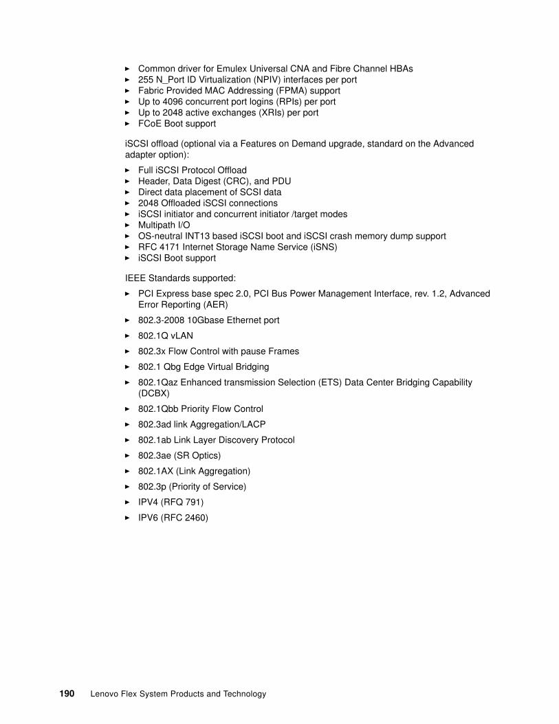
� Common driver for Emulex Universal CNA and Fibre Channel HBAs� 255 N_Port ID Virtualization (NPIV) interfaces per port� Fabric Provided MAC Addressing (FPMA) support� Up to 4096 concurrent port logins (RPIs) per port� Up to 2048 active exchanges (XRIs) per port� FCoE Boot support
iSCSI offload (optional via a Features on Demand upgrade, standard on the Advanced adapter option):
� Full iSCSI Protocol Offload� Header, Data Digest (CRC), and PDU� Direct data placement of SCSI data� 2048 Offloaded iSCSI connections� iSCSI initiator and concurrent initiator /target modes� Multipath I/O� OS-neutral INT13 based iSCSI boot and iSCSI crash memory dump support� RFC 4171 Internet Storage Name Service (iSNS)� iSCSI Boot support
IEEE Standards supported:
� PCI Express base spec 2.0, PCI Bus Power Management Interface, rev. 1.2, Advanced Error Reporting (AER)
� 802.3-2008 10Gbase Ethernet port
� 802.1Q vLAN
� 802.3x Flow Control with pause Frames
� 802.1 Qbg Edge Virtual Bridging
� 802.1Qaz Enhanced transmission Selection (ETS) Data Center Bridging Capability (DCBX)
� 802.1Qbb Priority Flow Control
� 802.3ad link Aggregation/LACP
� 802.1ab Link Layer Discovery Protocol
� 802.3ae (SR Optics)
� 802.1AX (Link Aggregation)
� 802.3p (Priority of Service)
� IPV4 (RFQ 791)
� IPV6 (RFC 2460)
190 Lenovo Flex System Products and Technology
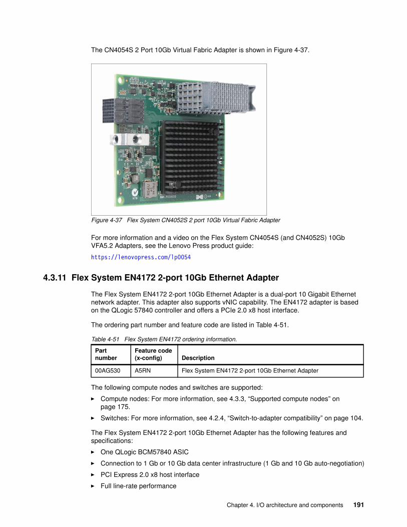
The CN4054S 2 Port 10Gb Virtual Fabric Adapter is shown in Figure 4-37.
Figure 4-37 Flex System CN4052S 2 port 10Gb Virtual Fabric Adapter
For more information and a video on the Flex System CN4054S (and CN4052S) 10Gb VFA5.2 Adapters, see the Lenovo Press product guide:
https://lenovopress.com/lp0054
4.3.11 Flex System EN4172 2-port 10Gb Ethernet Adapter
The Flex System EN4172 2-port 10Gb Ethernet Adapter is a dual-port 10 Gigabit Ethernet network adapter. This adapter also supports vNIC capability. The EN4172 adapter is based on the QLogic 57840 controller and offers a PCIe 2.0 x8 host interface.
The ordering part number and feature code are listed in Table 4-51.
Table 4-51 Flex System EN4172 ordering information.
The following compute nodes and switches are supported:
� Compute nodes: For more information, see 4.3.3, “Supported compute nodes” on page 175.
� Switches: For more information, see 4.2.4, “Switch-to-adapter compatibility” on page 104.
The Flex System EN4172 2-port 10Gb Ethernet Adapter has the following features and specifications:
� One QLogic BCM57840 ASIC
� Connection to 1 Gb or 10 Gb data center infrastructure (1 Gb and 10 Gb auto-negotiation)
� PCI Express 2.0 x8 host interface
� Full line-rate performance
Partnumber
Feature code(x-config) Description
00AG530 A5RN Flex System EN4172 2-port 10Gb Ethernet Adapter
Chapter 4. I/O architecture and components 191
� Supports 10 Gb Ethernet
� Ethernet features:
– Ethernet frame: 1500 byte or 9600 byte (jumbo frame)
– VLAN support with VLAN tagging
– vNIC support:
• Supports Switch Independent Mode (vNIC2 mode)• UFP mode support • Four vNIC/NPAR Ethernet devices per 10 Gb physical port
– Stateless offload:
• IP, TCP, and UDP checksum offloads• IPv4 and IPv6 offloads• Large send offload (LSO)
– Performance optimization:
• Receive Side Scaling (RSS)• Transmit Side Scaling (TSS)• MSI and MSI-X support• RX/TX multiqueue• TCP offload Engine (TOE) support
– SR-IOV-ready
– Wake on LAN
– Preboot eXecution Environment (PXE) support
– Network teaming, failover, and load balancing:
• Smart Load Balancing (SLB)• Link Aggregation Control Protocol (LACP) and generic trunking
– Management that uses Broadcom Advanced Control Suite management application
– Compliance:
• IEEE 802.3ae (10 Gb Ethernet)• IEEE 802.3ad (Link aggregation)• IEEE 802.3ap Clause73 1G/10G Autonegotiation for 10GBase-KR channels• IEEE 802.1q (VLAN)• IEEE 802.1p (Priority Encoding)• IEEE 802.3x (Flow Control)• IEEE 802.1au (Congestion Notification)• IPv4 (RFQ 791)• IPv6 (RFC 2460)• IEEE 1588/802.1as PTP• IEEE 802.1Qbb PFC• IEEE 802.1Qaz ETS• IEEE 802.1Qaz DCBX Protocol
192 Lenovo Flex System Products and Technology
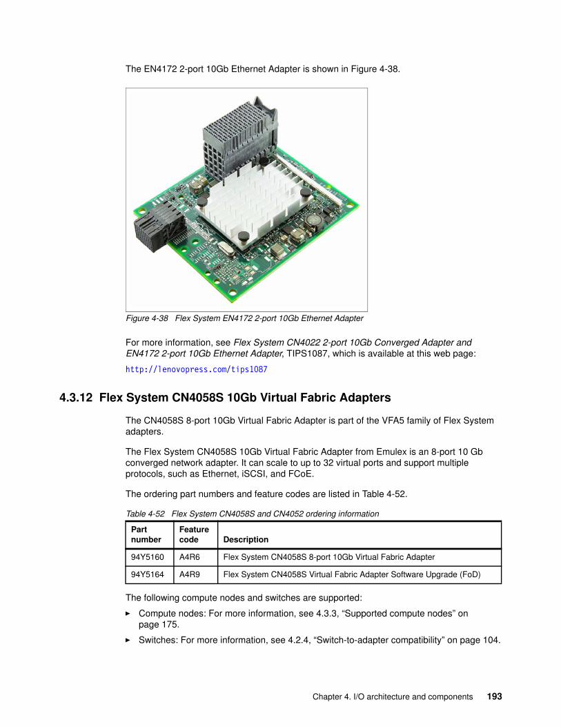
The EN4172 2-port 10Gb Ethernet Adapter is shown in Figure 4-38.
Figure 4-38 Flex System EN4172 2-port 10Gb Ethernet Adapter
For more information, see Flex System CN4022 2-port 10Gb Converged Adapter and EN4172 2-port 10Gb Ethernet Adapter, TIPS1087, which is available at this web page:
http://lenovopress.com/tips1087
4.3.12 Flex System CN4058S 10Gb Virtual Fabric Adapters
The CN4058S 8-port 10Gb Virtual Fabric Adapter is part of the VFA5 family of Flex System adapters.
The Flex System CN4058S 10Gb Virtual Fabric Adapter from Emulex is an 8-port 10 Gb converged network adapter. It can scale to up to 32 virtual ports and support multiple protocols, such as Ethernet, iSCSI, and FCoE.
The ordering part numbers and feature codes are listed in Table 4-52.
Table 4-52 Flex System CN4058S and CN4052 ordering information
The following compute nodes and switches are supported:
� Compute nodes: For more information, see 4.3.3, “Supported compute nodes” on page 175.
� Switches: For more information, see 4.2.4, “Switch-to-adapter compatibility” on page 104.
Partnumber
Featurecode Description
94Y5160 A4R6 Flex System CN4058S 8-port 10Gb Virtual Fabric Adapter
94Y5164 A4R9 Flex System CN4058S Virtual Fabric Adapter Software Upgrade (FoD)
Chapter 4. I/O architecture and components 193
The Flex System CN4058S 8-port 10Gb Virtual Fabric Adapter has the following features and specifications:
� Eight-port 10 Gb Ethernet adapter� Dual-ASIC controller that uses the Emulex XE104 design� Two PCIe Express 3.0 x8 host interfaces (8 GTps)� MSI-X support � Fabric Manager support� Power consumption: 25 W maximum
The following Ethernet features are included in the adapter:
� IPv4/IPv6 TCP and UDP checksum offload, Large Send offload (LSO), Large Receive offload, Receive Side Scaling (RSS), and TCP Segmentation offload (TSO)
� VLAN insertion and extraction
� Jumbo frames up to 9216 Bytes
� PFC for Ethernet traffic
� Interrupt coalescing
� Load balancing and failover support, including adapter fault tolerance (AFT), switch fault tolerance (SFT), adaptive load balancing (ALB), link aggregation, and IEEE 802.1AX
� 4 PCIe Physical Functions (PFs) per port
� 31 PCIe Virtual Functions (VFs) for NIC per port configurable
� Advance Error Reporting (AER)
� Supports D0, D3 (hot and cold) power management modes
� Completion Timeout (CTO)
� Function Level Reset (FLR)
� Network boot support:
– PXE Boot– iSCSI Boot (with FoD upgrade)– FCoE Boot (with FoD upgrade)
� Virtual Fabric support:
– Virtual Fabric mode (vNIC1)– Switch Independent mode (vNIC2)– Unified Fabric Port (UFP) support
� Emulex VNeX Technology full hardware offload support:
– Increases VM Density and decreases CPU power draw
– Microsoft Network Virtualization that uses Generic Routing Encapsulation (NVGRE)
– VMware Virtual Extensible LAN (VXLAN)
– VM mobility acceleration, which offloads header encapsulation from processor to network controller
� Remote Direct Memory Access over Converged Ethernet (RoCE) support:
– Accelerates application and storage I/O operations– Supports Windows Server SMB Direct– Required to deliver low latency performance
� Single Root I/O Virtualization (SRIOV) support:
– Maximum of 128 Virtual Functions – Minimizes VM I/O overhead and improves adapter performance
194 Lenovo Flex System Products and Technology
The following FCoE features (with FoD upgrade) are included:
� Hardware offloads of Ethernet TCP/IP� ANSI T11 FC-BB-5 Support� Programmable worldwide name (WWN)� Support for FIP and FCoE Ether Types� Support for up to 255 NPIV Interfaces per port� FCoE Initiator� Common driver for Emulex Universal CNA and Fibre Channel HBAs� Fabric Provided MAC Addressing (FPMA) support� 1024 concurrent port logins (RPIs) per port� 1024 active exchanges (XRIs) per port
The following iSCSI features (with FoD upgrade) are included:
� Full iSCSI Protocol offload� Header, Data Digest (CRC), and PDU� Direct data placement of SCSI data� 2048 Offloaded iSCSI connections� iSCSI initiator and concurrent initiator or target modes� Multipath I/O� OS-independent INT13 based iSCSI boot and iSCSI crash dump support� RFC 4171 Internet Storage Name Service (iSNS)
The adapter supports the following IEEE standards:
� PCI Express base spec 2.0, PCI Bus Power Management Interface, rev. 1.2, Advanced Error Reporting (AER)
� 802.3-2008 10Gbase Ethernet port
� 802.1Q vLAN
� 802.3x Flow Control with pause Frames
� 802.1 Qbg Edge Virtual Bridging
� 802.1Qaz ETS Data Center Bridging Capability (DCBX)
� 802.1Qbb Priority Flow Control
� 802.3ad link Aggregation/LACP
� 802.1ab Link Layer Discovery Protocol
� 802.3ae (SR Optics)
� 802.1AX (Link Aggregation)
� 802.3p (Priority of Service)
� IPV4 (RFQ 791)
� IPV6 (RFC 2460)
Chapter 4. I/O architecture and components 195
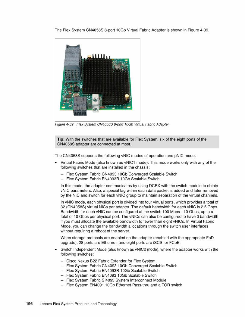
The Flex System CN4058S 8-port 10Gb Virtual Fabric Adapter is shown in Figure 4-39.
Figure 4-39 Flex System CN4058S 8-port 10Gb Virtual Fabric Adapter
The CN4058S supports the following vNIC modes of operation and pNIC mode:
� Virtual Fabric Mode (also known as vNIC1 mode). This mode works only with any of the following switches that are installed in the chassis:
– Flex System Fabric CN4093 10Gb Converged Scalable Switch – Flex System Fabric EN4093R 10Gb Scalable Switch
In this mode, the adapter communicates by using DCBX with the switch module to obtain vNIC parameters. Also, a special tag within each data packet is added and later removed by the NIC and switch for each vNIC group to maintain separation of the virtual channels.
In vNIC mode, each physical port is divided into four virtual ports, which provides a total of 32 (CN4058S) virtual NICs per adapter. The default bandwidth for each vNIC is 2.5 Gbps. Bandwidth for each vNIC can be configured at the switch 100 Mbps - 10 Gbps, up to a total of 10 Gbps per physical port. The vNICs can also be configured to have 0 bandwidth if you must allocate the available bandwidth to fewer than eight vNICs. In Virtual Fabric Mode, you can change the bandwidth allocations through the switch user interfaces without requiring a reboot of the server.
When storage protocols are enabled on the adapter (enabled with the appropriate FoD upgrade), 28 ports are Ethernet, and eight ports are iSCSI or FCoE.
� Switch Independent Mode (also known as vNIC2 mode), where the adapter works with the following switches:
– Cisco Nexus B22 Fabric Extender for Flex System – Flex System Fabric CN4093 10Gb Converged Scalable Switch – Flex System Fabric EN4093R 10Gb Scalable Switch – Flex System Fabric EN4093 10Gb Scalable Switch – Flex System Fabric SI4093 System Interconnect Module – Flex System EN4091 10Gb Ethernet Pass-thru and a TOR switch
Tip: With the switches that are available for Flex System, six of the eight ports of the CN4058S adapter are connected at most.
196 Lenovo Flex System Products and Technology
Switch Independent Mode offers the same capabilities as Virtual Fabric Mode in terms of the number of vNICs and the bandwidth that each can be configured to include. However, Switch Independent Mode extends the customer VLANs to the virtual NIC interfaces. The IEEE 802.1Q VLAN tag is essential to the separation of the vNIC groups by the NIC adapter or driver and the switch. The VLAN tags are added to the packet by the applications or drivers at each endstation rather than by the switch.
� Unified Fabric Port (UFP) provides a feature-rich solution compared to the original vNIC Virtual Fabric mode. As with Virtual Fabric mode vNIC, UFP allows carving up a single 10 Gb port into four virtual NICs (called vPorts in UFP). UFP also has the following associated modes:
– Tunnel mode: Provides Q-in-Q mode, where the vPort is customer VLAN-independent (similar to vNIC Virtual Fabric Dedicated Uplink Mode).
– Trunk mode: Provides a traditional 802.1Q trunk mode (multi-VLAN trunk link) to the virtual NIC (vPort) interface; that is, permits host side tagging.
– Access mode: Provides a traditional access mode (single untagged VLAN) to the virtual NIC (vPort) interface, which is similar to a physical port in access mode.
– FCoE mode: Provides FCoE functionality to the vPort.
– Auto-VLAN mode: Auto VLAN creation for Qbg and VMready environments.
Only one vPort (vPort 2) per physical port can be bound to FCoE. If FCoE is not wanted, vPort 2 can be configured for one of the other modes. UFP works with the following switches:
– Flex System Fabric CN4093 10Gb Converged Scalable Switch – Flex System Fabric EN4093R 10Gb Scalable Switch – Flex System Fabric SI4093 System Interconnect Module
� In pNIC mode, the adapter can operate as a standard 10 Gbps or 1 Gbps 8-port (CN4058S) Ethernet expansion adapter. When in pNIC mode, the adapter functions with all supported I/O modules.
In pNIC mode, the adapter with the FoD upgrade applied operates in traditional Converged Network Adapter (CNA) mode with eight ports (CN4058S) of Ethernet and eight ports (CN4058S) of iSCSI or FCoE that are available to the operating system.
4.3.13 Flex System FC3172 2-port 8Gb FC Adapter
The Flex System FC3172 2-port 8Gb FC Adapter from QLogic enables high-speed access for Flex System Enterprise Chassis compute nodes to connect to a Fibre Channel SAN. This adapter is based on the proven QLogic 2532 8 Gb ASIC design. It works with any of the 8 Gb or 16 Gb Flex System Fibre Channel switch modules.
The ordering part number and feature code are listed in Table 4-53.
Table 4-53 Flex System FC3172 2-port 8 Gb FC Adapter ordering information
The following compute nodes and switches are supported:
� Compute nodes: For more information, see 4.3.3, “Supported compute nodes” on page 175.
� Switches: For more information, see 4.2.4, “Switch-to-adapter compatibility” on page 104.
Partnumber
Feature code(x-config) Description
69Y1938 A1BM FC3172 2-port 8Gb FC Adapter
Chapter 4. I/O architecture and components 197
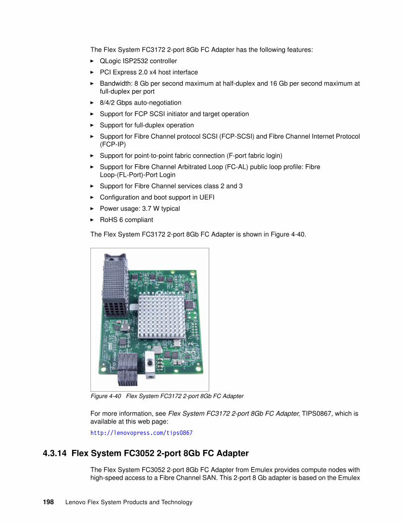
The Flex System FC3172 2-port 8Gb FC Adapter has the following features:
� QLogic ISP2532 controller
� PCI Express 2.0 x4 host interface
� Bandwidth: 8 Gb per second maximum at half-duplex and 16 Gb per second maximum at full-duplex per port
� 8/4/2 Gbps auto-negotiation
� Support for FCP SCSI initiator and target operation
� Support for full-duplex operation
� Support for Fibre Channel protocol SCSI (FCP-SCSI) and Fibre Channel Internet Protocol (FCP-IP)
� Support for point-to-point fabric connection (F-port fabric login)
� Support for Fibre Channel Arbitrated Loop (FC-AL) public loop profile: Fibre Loop-(FL-Port)-Port Login
� Support for Fibre Channel services class 2 and 3
� Configuration and boot support in UEFI
� Power usage: 3.7 W typical
� RoHS 6 compliant
The Flex System FC3172 2-port 8Gb FC Adapter is shown in Figure 4-40.
Figure 4-40 Flex System FC3172 2-port 8Gb FC Adapter
For more information, see Flex System FC3172 2-port 8Gb FC Adapter, TIPS0867, which is available at this web page:
http://lenovopress.com/tips0867
4.3.14 Flex System FC3052 2-port 8Gb FC Adapter
The Flex System FC3052 2-port 8Gb FC Adapter from Emulex provides compute nodes with high-speed access to a Fibre Channel SAN. This 2-port 8 Gb adapter is based on the Emulex
198 Lenovo Flex System Products and Technology
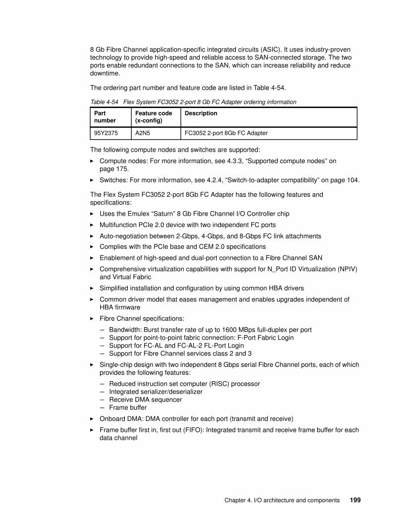
8 Gb Fibre Channel application-specific integrated circuits (ASIC). It uses industry-proven technology to provide high-speed and reliable access to SAN-connected storage. The two ports enable redundant connections to the SAN, which can increase reliability and reduce downtime.
The ordering part number and feature code are listed in Table 4-54.
Table 4-54 Flex System FC3052 2-port 8 Gb FC Adapter ordering information
The following compute nodes and switches are supported:
� Compute nodes: For more information, see 4.3.3, “Supported compute nodes” on page 175.
� Switches: For more information, see 4.2.4, “Switch-to-adapter compatibility” on page 104.
The Flex System FC3052 2-port 8Gb FC Adapter has the following features and specifications:
� Uses the Emulex “Saturn” 8 Gb Fibre Channel I/O Controller chip
� Multifunction PCIe 2.0 device with two independent FC ports
� Auto-negotiation between 2-Gbps, 4-Gbps, and 8-Gbps FC link attachments
� Complies with the PCIe base and CEM 2.0 specifications
� Enablement of high-speed and dual-port connection to a Fibre Channel SAN
� Comprehensive virtualization capabilities with support for N_Port ID Virtualization (NPIV) and Virtual Fabric
� Simplified installation and configuration by using common HBA drivers
� Common driver model that eases management and enables upgrades independent of HBA firmware
� Fibre Channel specifications:
– Bandwidth: Burst transfer rate of up to 1600 MBps full-duplex per port– Support for point-to-point fabric connection: F-Port Fabric Login– Support for FC-AL and FC-AL-2 FL-Port Login– Support for Fibre Channel services class 2 and 3
� Single-chip design with two independent 8 Gbps serial Fibre Channel ports, each of which provides the following features:
– Reduced instruction set computer (RISC) processor– Integrated serializer/deserializer– Receive DMA sequencer– Frame buffer
� Onboard DMA: DMA controller for each port (transmit and receive)
� Frame buffer first in, first out (FIFO): Integrated transmit and receive frame buffer for each data channel
Partnumber
Feature code(x-config)
Description
95Y2375 A2N5 FC3052 2-port 8Gb FC Adapter
Chapter 4. I/O architecture and components 199
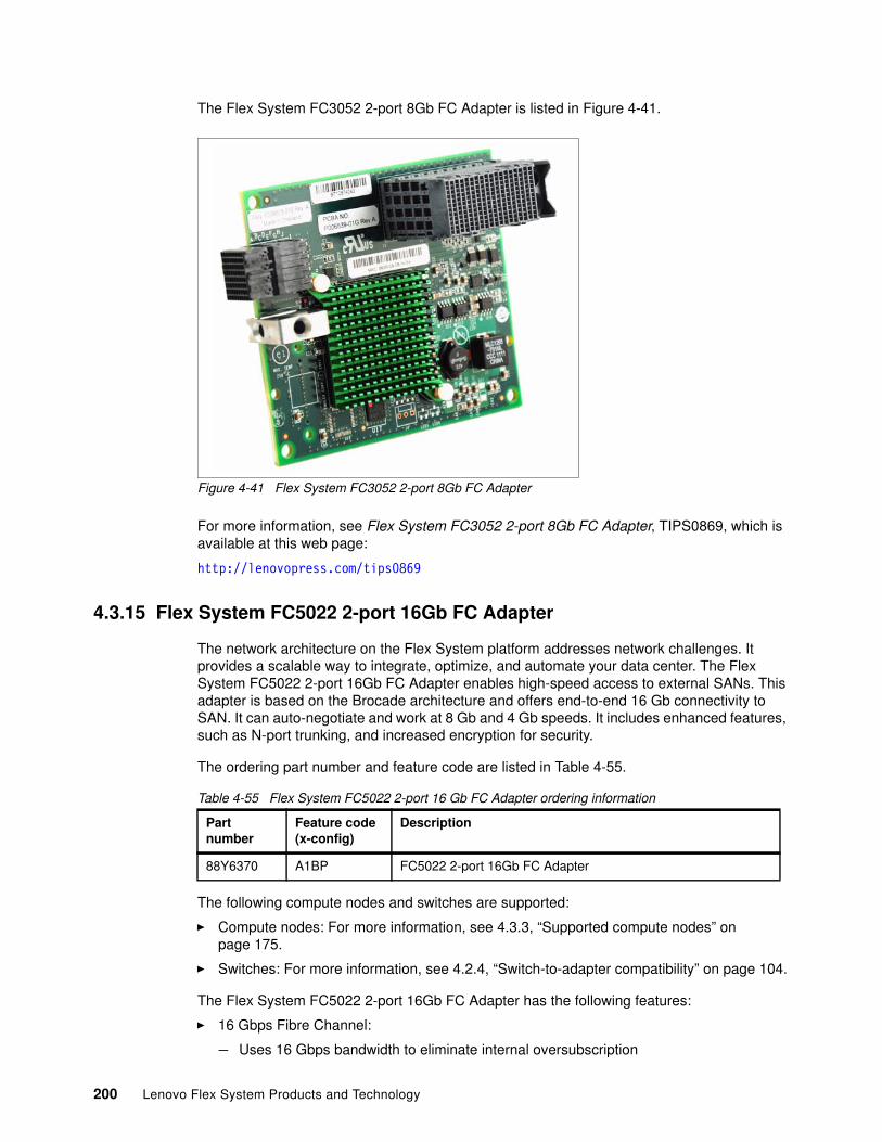
The Flex System FC3052 2-port 8Gb FC Adapter is listed in Figure 4-41.
Figure 4-41 Flex System FC3052 2-port 8Gb FC Adapter
For more information, see Flex System FC3052 2-port 8Gb FC Adapter, TIPS0869, which is available at this web page:
http://lenovopress.com/tips0869
4.3.15 Flex System FC5022 2-port 16Gb FC Adapter
The network architecture on the Flex System platform addresses network challenges. It provides a scalable way to integrate, optimize, and automate your data center. The Flex System FC5022 2-port 16Gb FC Adapter enables high-speed access to external SANs. This adapter is based on the Brocade architecture and offers end-to-end 16 Gb connectivity to SAN. It can auto-negotiate and work at 8 Gb and 4 Gb speeds. It includes enhanced features, such as N-port trunking, and increased encryption for security.
The ordering part number and feature code are listed in Table 4-55.
Table 4-55 Flex System FC5022 2-port 16 Gb FC Adapter ordering information
The following compute nodes and switches are supported:
� Compute nodes: For more information, see 4.3.3, “Supported compute nodes” on page 175.
� Switches: For more information, see 4.2.4, “Switch-to-adapter compatibility” on page 104.
The Flex System FC5022 2-port 16Gb FC Adapter has the following features:
� 16 Gbps Fibre Channel:
– Uses 16 Gbps bandwidth to eliminate internal oversubscription
Partnumber
Feature code(x-config)
Description
88Y6370 A1BP FC5022 2-port 16Gb FC Adapter
200 Lenovo Flex System Products and Technology
– Investment protection with the latest Fibre Channel technologies– Reduces the number of ISL external switch ports, optics, cables, and power
� Over 500,000 IOPS per port, which maximizes transaction performance and the density of VMs per compute node.
� Achieves performance of 315,000 IOPS for email exchange and 205,000 IOPS for SQL Database.
� Boot from SAN allows the automation SAN Boot LUN discovery to simplify boot from SAN and reduce image management complexity.
� Brocade Server Application Optimization (SAO) provides QoS levels that are assignable to VM applications.
� Direct I/O enables native (direct) I/O performance by allowing VMs to bypass the hypervisor and communicate directly with the adapter.
� Brocade Network Advisor simplifies and unifies the management of Brocade adapter, SAN, and LAN resources through a single user interface.
� LUN Masking, which is an Initiator-based LUN masking for storage traffic isolation.
� NPIV allows multiple host initiator N_Ports to share a single physical N_Port, which dramatically reduces SAN hardware requirements.
� Target Rate Limiting (TRL) throttles data traffic when accessing slower speed storage targets to avoid back pressure problems.
� RoHS-6 compliant.
The Flex System FC5022 2-port 16Gb FC Adapter is shown in Figure 4-42.
Figure 4-42 Flex System FC5022 2-port 16Gb FC Adapter
For more information, see Flex System FC5022 2-port 16Gb FC Adapter, TIPS0891, which is available at this web page:
http://lenovopress.com/tips0891
4.3.16 Flex System FC5052 2-port and FC5054 4-port 16Gb FC adapters
The network architecture on the Flex System platform is designed to address network challenges and provide a scalable way to integrate, optimize, and automate the data center. The Flex System FC5052 2-port and FC5054 4-port 16Gb FC adapters enable high-speed access for Flex System compute nodes to an external SAN. These adapters are based on the
Chapter 4. I/O architecture and components 201
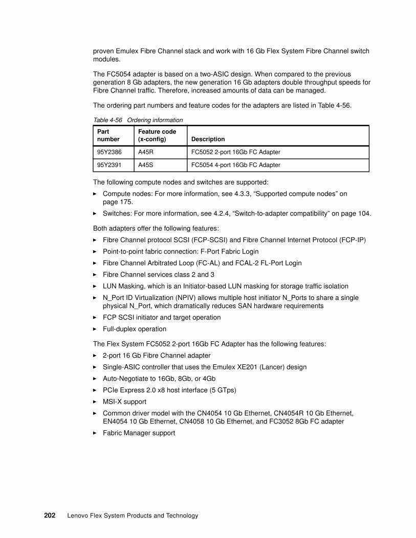
proven Emulex Fibre Channel stack and work with 16 Gb Flex System Fibre Channel switch modules.
The FC5054 adapter is based on a two-ASIC design. When compared to the previous generation 8 Gb adapters, the new generation 16 Gb adapters double throughput speeds for Fibre Channel traffic. Therefore, increased amounts of data can be managed.
The ordering part numbers and feature codes for the adapters are listed in Table 4-56.
Table 4-56 Ordering information
The following compute nodes and switches are supported:
� Compute nodes: For more information, see 4.3.3, “Supported compute nodes” on page 175.
� Switches: For more information, see 4.2.4, “Switch-to-adapter compatibility” on page 104.
Both adapters offer the following features:
� Fibre Channel protocol SCSI (FCP-SCSI) and Fibre Channel Internet Protocol (FCP-IP)
� Point-to-point fabric connection: F-Port Fabric Login
� Fibre Channel Arbitrated Loop (FC-AL) and FCAL-2 FL-Port Login
� Fibre Channel services class 2 and 3
� LUN Masking, which is an Initiator-based LUN masking for storage traffic isolation
� N_Port ID Virtualization (NPIV) allows multiple host initiator N_Ports to share a single physical N_Port, which dramatically reduces SAN hardware requirements
� FCP SCSI initiator and target operation
� Full-duplex operation
The Flex System FC5052 2-port 16Gb FC Adapter has the following features:
� 2-port 16 Gb Fibre Channel adapter
� Single-ASIC controller that uses the Emulex XE201 (Lancer) design
� Auto-Negotiate to 16Gb, 8Gb, or 4Gb
� PCIe Express 2.0 x8 host interface (5 GTps)
� MSI-X support
� Common driver model with the CN4054 10 Gb Ethernet, CN4054R 10 Gb Ethernet, EN4054 10 Gb Ethernet, CN4058 10 Gb Ethernet, and FC3052 8Gb FC adapter
� Fabric Manager support
Partnumber
Feature code(x-config) Description
95Y2386 A45R FC5052 2-port 16Gb FC Adapter
95Y2391 A45S FC5054 4-port 16Gb FC Adapter
202 Lenovo Flex System Products and Technology
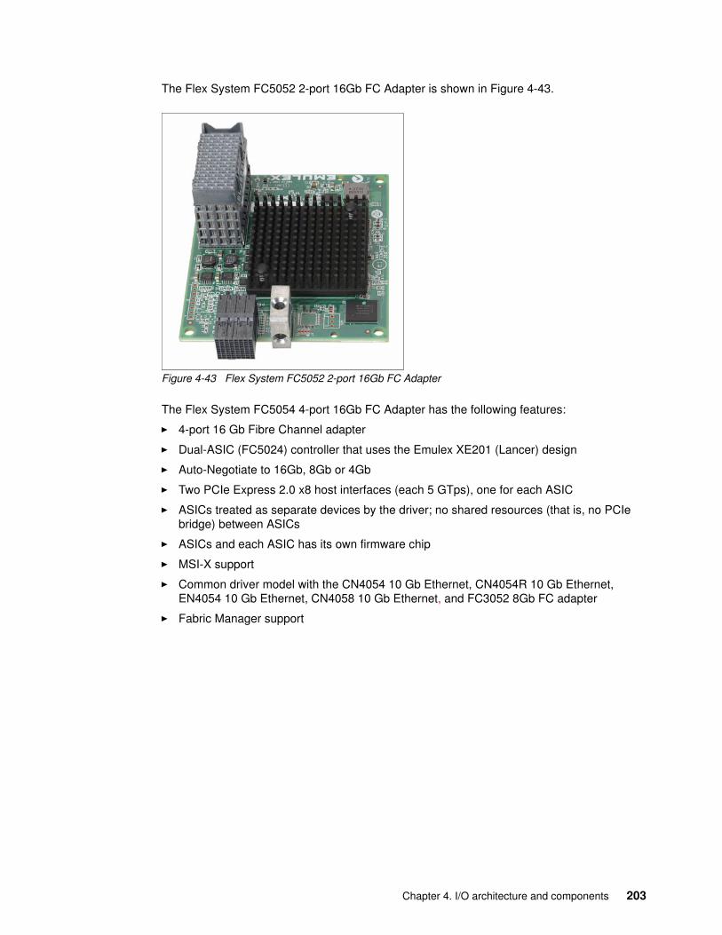
The Flex System FC5052 2-port 16Gb FC Adapter is shown in Figure 4-43.
Figure 4-43 Flex System FC5052 2-port 16Gb FC Adapter
The Flex System FC5054 4-port 16Gb FC Adapter has the following features:
� 4-port 16 Gb Fibre Channel adapter
� Dual-ASIC (FC5024) controller that uses the Emulex XE201 (Lancer) design
� Auto-Negotiate to 16Gb, 8Gb or 4Gb
� Two PCIe Express 2.0 x8 host interfaces (each 5 GTps), one for each ASIC
� ASICs treated as separate devices by the driver; no shared resources (that is, no PCIe bridge) between ASICs
� ASICs and each ASIC has its own firmware chip
� MSI-X support
� Common driver model with the CN4054 10 Gb Ethernet, CN4054R 10 Gb Ethernet, EN4054 10 Gb Ethernet, CN4058 10 Gb Ethernet, and FC3052 8Gb FC adapter
� Fabric Manager support
Chapter 4. I/O architecture and components 203
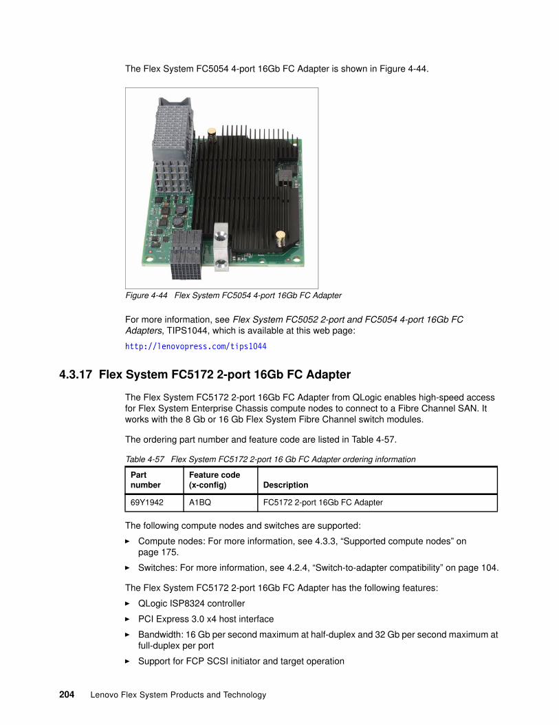
The Flex System FC5054 4-port 16Gb FC Adapter is shown in Figure 4-44.
Figure 4-44 Flex System FC5054 4-port 16Gb FC Adapter
For more information, see Flex System FC5052 2-port and FC5054 4-port 16Gb FC Adapters, TIPS1044, which is available at this web page:
http://lenovopress.com/tips1044
4.3.17 Flex System FC5172 2-port 16Gb FC Adapter
The Flex System FC5172 2-port 16Gb FC Adapter from QLogic enables high-speed access for Flex System Enterprise Chassis compute nodes to connect to a Fibre Channel SAN. It works with the 8 Gb or 16 Gb Flex System Fibre Channel switch modules.
The ordering part number and feature code are listed in Table 4-57.
Table 4-57 Flex System FC5172 2-port 16 Gb FC Adapter ordering information
The following compute nodes and switches are supported:
� Compute nodes: For more information, see 4.3.3, “Supported compute nodes” on page 175.
� Switches: For more information, see 4.2.4, “Switch-to-adapter compatibility” on page 104.
The Flex System FC5172 2-port 16Gb FC Adapter has the following features:
� QLogic ISP8324 controller
� PCI Express 3.0 x4 host interface
� Bandwidth: 16 Gb per second maximum at half-duplex and 32 Gb per second maximum at full-duplex per port
� Support for FCP SCSI initiator and target operation
Partnumber
Feature code(x-config) Description
69Y1942 A1BQ FC5172 2-port 16Gb FC Adapter
204 Lenovo Flex System Products and Technology
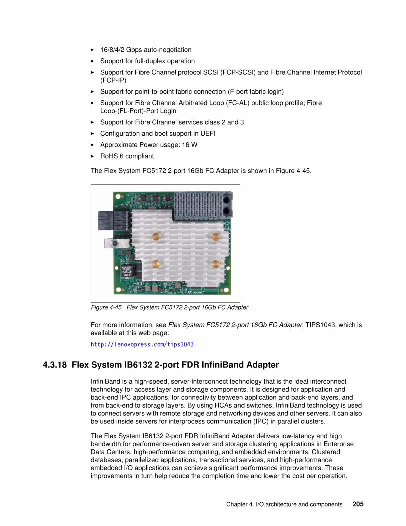
� 16/8/4/2 Gbps auto-negotiation
� Support for full-duplex operation
� Support for Fibre Channel protocol SCSI (FCP-SCSI) and Fibre Channel Internet Protocol (FCP-IP)
� Support for point-to-point fabric connection (F-port fabric login)
� Support for Fibre Channel Arbitrated Loop (FC-AL) public loop profile; Fibre Loop-(FL-Port)-Port Login
� Support for Fibre Channel services class 2 and 3
� Configuration and boot support in UEFI
� Approximate Power usage: 16 W
� RoHS 6 compliant
The Flex System FC5172 2-port 16Gb FC Adapter is shown in Figure 4-45.
Figure 4-45 Flex System FC5172 2-port 16Gb FC Adapter
For more information, see Flex System FC5172 2-port 16Gb FC Adapter, TIPS1043, which is available at this web page:
http://lenovopress.com/tips1043
4.3.18 Flex System IB6132 2-port FDR InfiniBand Adapter
InfiniBand is a high-speed, server-interconnect technology that is the ideal interconnect technology for access layer and storage components. It is designed for application and back-end IPC applications, for connectivity between application and back-end layers, and from back-end to storage layers. By using HCAs and switches, InfiniBand technology is used to connect servers with remote storage and networking devices and other servers. It can also be used inside servers for interprocess communication (IPC) in parallel clusters.
The Flex System IB6132 2-port FDR InfiniBand Adapter delivers low-latency and high bandwidth for performance-driven server and storage clustering applications in Enterprise Data Centers, high-performance computing, and embedded environments. Clustered databases, parallelized applications, transactional services, and high-performance embedded I/O applications can achieve significant performance improvements. These improvements in turn help reduce the completion time and lower the cost per operation.
Chapter 4. I/O architecture and components 205
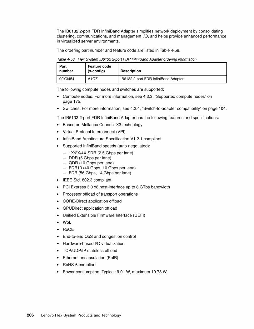
The IB6132 2-port FDR InfiniBand Adapter simplifies network deployment by consolidating clustering, communications, and management I/O, and helps provide enhanced performance in virtualized server environments.
The ordering part number and feature code are listed in Table 4-58.
Table 4-58 Flex System IB6132 2-port FDR InfiniBand Adapter ordering information
The following compute nodes and switches are supported:
� Compute nodes: For more information, see 4.3.3, “Supported compute nodes” on page 175.
� Switches: For more information, see 4.2.4, “Switch-to-adapter compatibility” on page 104.
The IB6132 2-port FDR InfiniBand Adapter has the following features and specifications:
� Based on Mellanox Connect-X3 technology
� Virtual Protocol Interconnect (VPI)
� InfiniBand Architecture Specification V1.2.1 compliant
� Supported InfiniBand speeds (auto-negotiated):
– 1X/2X/4X SDR (2.5 Gbps per lane)– DDR (5 Gbps per lane)– QDR (10 Gbps per lane)– FDR10 (40 Gbps, 10 Gbps per lane)– FDR (56 Gbps, 14 Gbps per lane)
� IEEE Std. 802.3 compliant
� PCI Express 3.0 x8 host-interface up to 8 GTps bandwidth
� Processor offload of transport operations
� CORE-Direct application offload
� GPUDirect application offload
� Unified Extensible Firmware Interface (UEFI)
� WoL
� RoCE
� End-to-end QoS and congestion control
� Hardware-based I/O virtualization
� TCP/UDP/IP stateless offload
� Ethernet encapsulation (EoIB)
� RoHS-6 compliant
� Power consumption: Typical: 9.01 W, maximum 10.78 W
Partnumber
Feature code(x-config) Description
90Y3454 A1QZ IB6132 2-port FDR InfiniBand Adapter
206 Lenovo Flex System Products and Technology
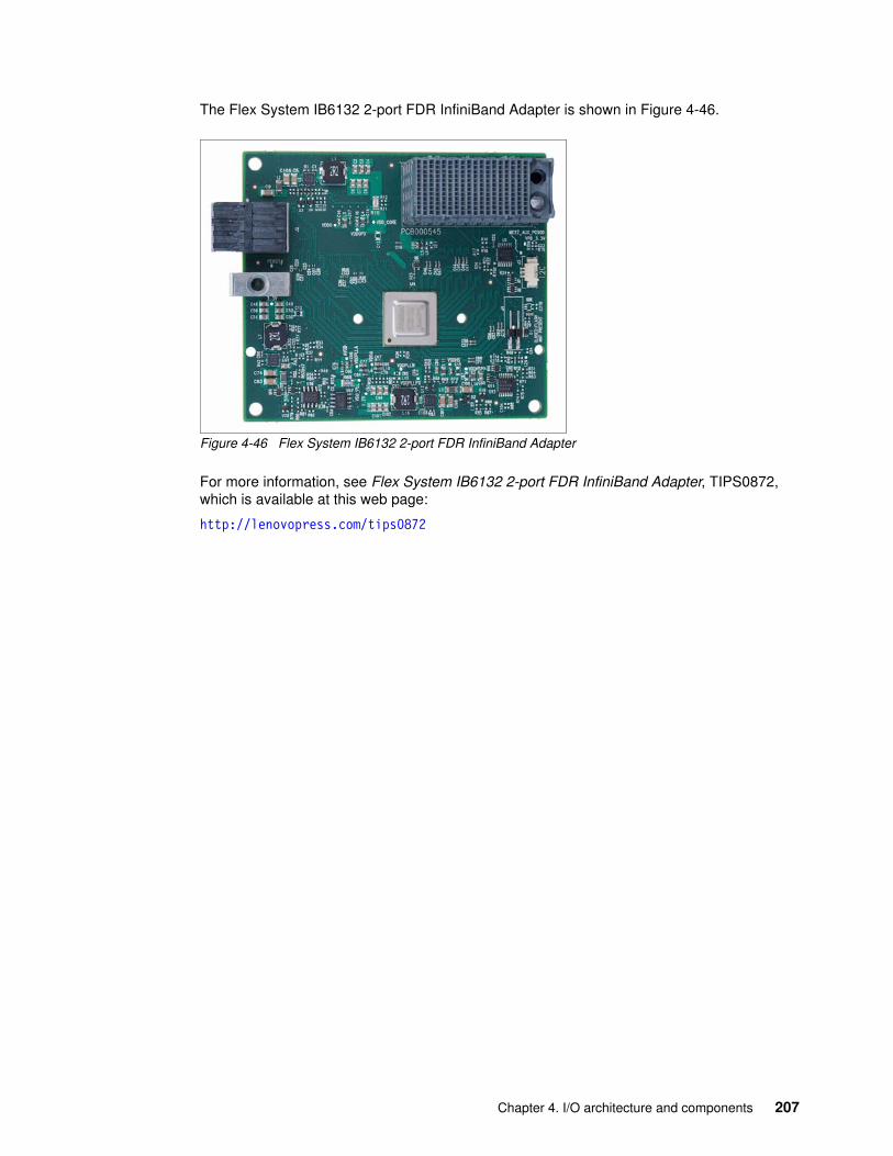
The Flex System IB6132 2-port FDR InfiniBand Adapter is shown in Figure 4-46.
Figure 4-46 Flex System IB6132 2-port FDR InfiniBand Adapter
For more information, see Flex System IB6132 2-port FDR InfiniBand Adapter, TIPS0872, which is available at this web page:
http://lenovopress.com/tips0872
Chapter 4. I/O architecture and components 207

208 Lenovo Flex System Products and Technology
© Copyright Lenovo 2018. All rights reserved. 209
Chapter 5. Compute nodes
This chapter describes the Flex System servers or compute nodes. The applications that are installed on the compute nodes can run natively on a dedicated physical server, or they can be virtualized in a virtual machine that is managed by a hypervisor layer.
Depending on the compute node design, nodes are available in one of the following form factors:
� Standard compute node: Occupies one chassis bay, half the width of the chassis (approximately 215 mm or 8.5 in.). An example is the ThinkSystem SN550 Compute Node.
� Double-wide compute node: Occupies two chassis bays side-by-side, the full width of the chassis (approximately 435 mm or 17 in.). An example is the ThinkSystem SN850 Compute Node.
This chapter includes the following topics:
� 5.1, “ThinkSystem SN550 Compute Node” on page 210� 5.2, “ThinkSystem SN850 Compute Node” on page 240� 5.3, “Flex System x240 M5 Compute Node (E5-2600 v4)” on page 276
5
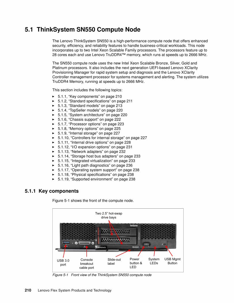
5.1 ThinkSystem SN550 Compute Node
The Lenovo ThinkSystem SN550 is a high-performance compute node that offers enhanced security, efficiency, and reliability features to handle business-critical workloads. This node incorporates up to two Intel Xeon Scalable Family processors. The processors feature up to 28 cores each and use Lenovo TruDDR4™ memory, which runs at speeds up to 2666 MHz.
The SN550 compute node uses the new Intel Xeon Scalable Bronze, Silver, Gold and Platinum processors. It also includes the next generation UEFI-based Lenovo XClarity Provisioning Manager for rapid system setup and diagnosis and the Lenovo XClarity Controller management processor for systems management and alerting. The system utilizes TruDDR4 Memory, running at speeds up to 2666 MHz.
This section includes the following topics:
� 5.1.1, “Key components” on page 210� 5.1.2, “Standard specifications” on page 211� 5.1.3, “Standard models” on page 213� 5.1.4, “TopSeller models” on page 220� 5.1.5, “System architecture” on page 220� 5.1.6, “Chassis support” on page 222� 5.1.7, “Processor options” on page 223� 5.1.8, “Memory options” on page 225� 5.1.9, “Internal storage” on page 227� 5.1.10, “Controllers for internal storage” on page 227� 5.1.11, “Internal drive options” on page 228� 5.1.12, “I/O expansion options” on page 231� 5.1.13, “Network adapters” on page 232� 5.1.14, “Storage host bus adapters” on page 233� 5.1.15, “Integrated virtualization” on page 233� 5.1.16, “Light path diagnostics” on page 236� 5.1.17, “Operating system support” on page 238� 5.1.18, “Physical specifications” on page 238� 5.1.19, “Supported environment” on page 238
5.1.1 Key components
Figure 5-1 shows the front of the compute node.
Figure 5-1 Front view of the ThinkSystem SN550 compute node
USB 3.0port
Consolebreakoutcable port
Two 2.5” hot-swapdrive bays
USB Mgmt Button
Powerbutton & LED
SystemLEDs
Slide-outlabel
210 Lenovo Flex System Products and Technology
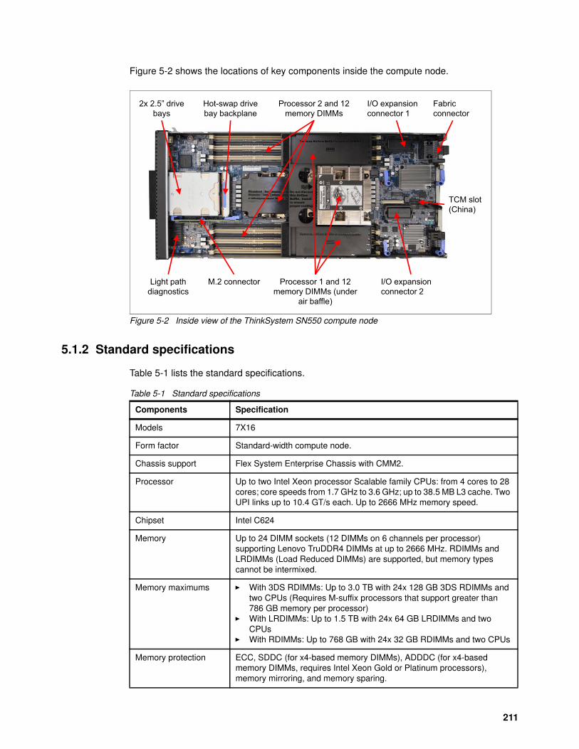
Figure 5-2 shows the locations of key components inside the compute node.
Figure 5-2 Inside view of the ThinkSystem SN550 compute node
5.1.2 Standard specifications
Table 5-1 lists the standard specifications.
Table 5-1 Standard specifications
Hot-swap drive bay backplane
Processor 2 and 12 memory DIMMs
I/O expansion connector 2
Light path diagnostics
Processor 1 and 12 memory DIMMs (under
air baffle)
I/O expansion connector 1
M.2 connector
TCM slot(China)
Fabricconnector
2x 2.5” drive bays
Components Specification
Models 7X16
Form factor Standard-width compute node.
Chassis support Flex System Enterprise Chassis with CMM2.
Processor Up to two Intel Xeon processor Scalable family CPUs: from 4 cores to 28 cores; core speeds from 1.7 GHz to 3.6 GHz; up to 38.5 MB L3 cache. Two UPI links up to 10.4 GT/s each. Up to 2666 MHz memory speed.
Chipset Intel C624
Memory Up to 24 DIMM sockets (12 DIMMs on 6 channels per processor) supporting Lenovo TruDDR4 DIMMs at up to 2666 MHz. RDIMMs and LRDIMMs (Load Reduced DIMMs) are supported, but memory types cannot be intermixed.
Memory maximums � With 3DS RDIMMs: Up to 3.0 TB with 24x 128 GB 3DS RDIMMs and two CPUs (Requires M-suffix processors that support greater than 786 GB memory per processor)
� With LRDIMMs: Up to 1.5 TB with 24x 64 GB LRDIMMs and two CPUs
� With RDIMMs: Up to 768 GB with 24x 32 GB RDIMMs and two CPUs
Memory protection ECC, SDDC (for x4-based memory DIMMs), ADDDC (for x4-based memory DIMMs, requires Intel Xeon Gold or Platinum processors), memory mirroring, and memory sparing.
211
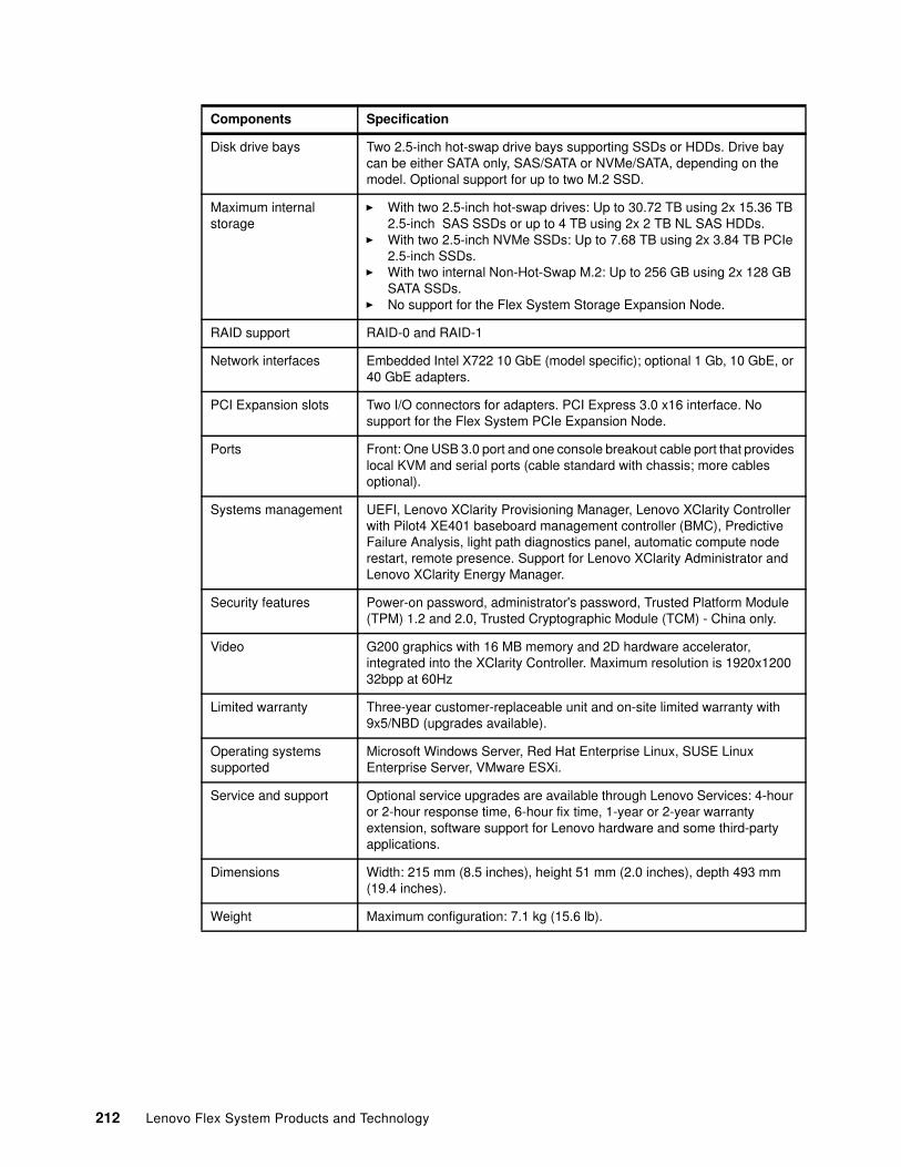
Disk drive bays Two 2.5-inch hot-swap drive bays supporting SSDs or HDDs. Drive bay can be either SATA only, SAS/SATA or NVMe/SATA, depending on the model. Optional support for up to two M.2 SSD.
Maximum internal storage
� With two 2.5-inch hot-swap drives: Up to 30.72 TB using 2x 15.36 TB 2.5-inch SAS SSDs or up to 4 TB using 2x 2 TB NL SAS HDDs.
� With two 2.5-inch NVMe SSDs: Up to 7.68 TB using 2x 3.84 TB PCIe 2.5-inch SSDs.
� With two internal Non-Hot-Swap M.2: Up to 256 GB using 2x 128 GB SATA SSDs.
� No support for the Flex System Storage Expansion Node.
RAID support RAID-0 and RAID-1
Network interfaces Embedded Intel X722 10 GbE (model specific); optional 1 Gb, 10 GbE, or 40 GbE adapters.
PCI Expansion slots Two I/O connectors for adapters. PCI Express 3.0 x16 interface. No support for the Flex System PCIe Expansion Node.
Ports Front: One USB 3.0 port and one console breakout cable port that provides local KVM and serial ports (cable standard with chassis; more cables optional).
Systems management UEFI, Lenovo XClarity Provisioning Manager, Lenovo XClarity Controller with Pilot4 XE401 baseboard management controller (BMC), Predictive Failure Analysis, light path diagnostics panel, automatic compute node restart, remote presence. Support for Lenovo XClarity Administrator and Lenovo XClarity Energy Manager.
Security features Power-on password, administrator's password, Trusted Platform Module (TPM) 1.2 and 2.0, Trusted Cryptographic Module (TCM) - China only.
Video G200 graphics with 16 MB memory and 2D hardware accelerator, integrated into the XClarity Controller. Maximum resolution is 1920x1200 32bpp at 60Hz
Limited warranty Three-year customer-replaceable unit and on-site limited warranty with 9x5/NBD (upgrades available).
Operating systems supported
Microsoft Windows Server, Red Hat Enterprise Linux, SUSE Linux Enterprise Server, VMware ESXi.
Service and support Optional service upgrades are available through Lenovo Services: 4-hour or 2-hour response time, 6-hour fix time, 1-year or 2-year warranty extension, software support for Lenovo hardware and some third-party applications.
Dimensions Width: 215 mm (8.5 inches), height 51 mm (2.0 inches), depth 493 mm (19.4 inches).
Weight Maximum configuration: 7.1 kg (15.6 lb).
Components Specification
212 Lenovo Flex System Products and Technology

5.1.3 Standard models
Table 5-2 lists the standard models.
Table 5-2 Standard models for Australia and New Zealand
Model Intel Xeon Processor (2 maximum)a
Memory Drivebays
RAID Drives M.2Drives
10 GbEa I/O slots (used / max)
7X16 A00FAU
1x Silver 4116 12C 85W 2.1GHz
1x 16GB 1Rx4
2x NVMe/ SATA
RSTe RAID Open Open 4x 10 GbEembedded
1 Used2 Max
7X16 A03EAU
1x Silver 4116 12C 85W 2.1GHz
1x 32GB 2x NVMe/ SATA
RSTe RAID Open Open 4x 10 GbEembedded
1 Used2 Max
7X16 A00MAU
1x Gold 5115 10C 85W 2.4GHz4
1x 16GB 1Rx
2x NVMe/ SATA
RSTe RAID Open Open 4x 10 GbEembedded
1 Used2 Max
7X16 A02DAU
1x Gold 5118 12C 105W 2.3GHz
1x 16GB 1Rx4
2x NVMe/ SATA
RSTe RAID Open Open 4x 10 GbEembedded
1 Used2 Max
7X16 A03KAU
1x Gold 5118 12C 105W 2.3GHz
1x 32GB 2x NVMe/ SATA
RSTe RAID Open Open 4x 10 GbEembedded
1 Used2 Max
7X16 A02EAU
1x Gold 5120 14C 105W 2.2GHz
1x 16GB 1Rx4
2x NVMe/ SATA
RSTe RAID Open Open 4x 10 GbEembedded
1 Used2 Max
7X16 A02YAU
1x Gold 5120 14C 105W 2.2GHz
1x 32GB 2x NVMe/ SATA
RSTe RAID Open Open 4x 10 GbEembedded
1 Used2 Max
7X16 A00WAU
1x Gold 6126 12C 125W 2.6GHz
1x 16GB 1Rx4
2x NVMe/ SATA
RSTe RAID Open Open 4x 10 GbEembedded
1 Used2 Max
X16 A033AU
1x Gold 6126 12C 125W 2.6GHz
1x 32GB 2x NVMe/ SATA
RSTe RAID Open Open 4x 10 GbEembedded
1 Used2 Max
7X16 A025AU
1x Gold 6130 16C 125W 2.1GHz
1x 16GB 1Rx4
2x NVMe/ SATA
RSTe RAID Open Open 4x 10 GbEembedded
1 Used2 Max
7X16 A03SAU
1x Gold 6130 16C 125W 2.1GHz
1x 32GB 2x NVMe/ SATA
RSTe RAID Open Open 4x 10 GbEembedded
1 Used2 Max
7X16 A03DAU
1x Gold 6134 8C 130W 3.2GHz
1x 32GB 2x NVMe/ SATA
RSTe RAID Open Open 4x 10 GbEembedded
1 Used2 Max
7X16 A028AU
1x Gold 6136 12C 150W 3.0GHz
1x 16GB 1Rx4
2x NVMe/ SATA
RSTe RAID Open Open 4x 10 GbEembedded
1 Used2 Max
7X16 A03PAU
1x Gold 6138 20C 125W 2.0GHz
1x 32GB 2x NVMe/ SATA
RSTe RAID Open Open 4x 10 GbEembedded
1 Used2 Max
7X16 A022AU
1x Gold 6140 18C 140W 2.3GHz
1x 16GB 1Rx4
2x NVMe/ SATA
RSTe RAID Open Open 4x 10 GbEembedded
1 Used2 Max
7X16 A037AU
1x Gold 6140 18C 140W 2.3GHz
1x 32GB 2x NVMe/ SATA
RSTe RAID Open Open 4x 10 GbEembedded
1 Used2 Max
7X16 A01EAU
1x Gold 6148 20C 150W 2.4GHz
1x 32GB 2x NVMe/ SATA
RSTe RAID Open Open 4x 10 GbEembedded
1 Used2 Max
7X16 A023AU
1x Gold 6150 18C 165W 2.7GHz
1x 32GB 2x NVMe/ SATA
RSTe RAID Open Open 4x 10 GbEembedded
1 Used2 Max
213
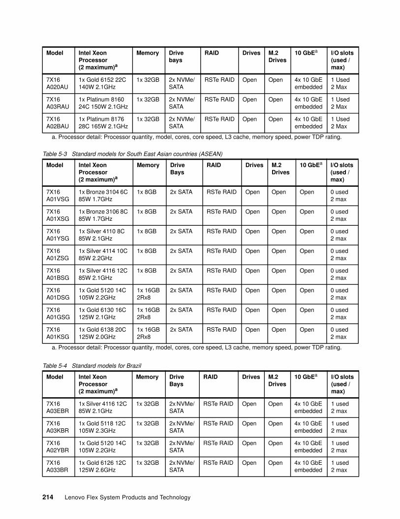
Table 5-3 Standard models for South East Asian countries (ASEAN)
Table 5-4 Standard models for Brazil
7X16 A020AU
1x Gold 6152 22C 140W 2.1GHz
1x 32GB 2x NVMe/ SATA
RSTe RAID Open Open 4x 10 GbEembedded
1 Used2 Max
7X16 A03RAU
1x Platinum 8160 24C 150W 2.1GHz
1x 32GB 2x NVMe/ SATA
RSTe RAID Open Open 4x 10 GbEembedded
1 Used2 Max
7X16 A02BAU
1x Platinum 8176 28C 165W 2.1GHz
1x 32GB 2x NVMe/ SATA
RSTe RAID Open Open 4x 10 GbEembedded
1 Used2 Max
a. Processor detail: Processor quantity, model, cores, core speed, L3 cache, memory speed, power TDP rating.
Model Intel Xeon Processor (2 maximum)a
a. Processor detail: Processor quantity, model, cores, core speed, L3 cache, memory speed, power TDP rating.
Memory Drive Bays
RAID Drives M.2 Drives
10 GbEa I/O slots (used / max)
7X16 A01VSG
1x Bronze 3104 6C 85W 1.7GHz
1x 8GB 2x SATA RSTe RAID Open Open Open 0 used2 max
7X16 A01XSG
1x Bronze 3106 8C 85W 1.7GHz
1x 8GB 2x SATA RSTe RAID Open Open Open 0 used2 max
7X16 A01YSG
1x Silver 4110 8C 85W 2.1GHz
1x 8GB 2x SATA RSTe RAID Open Open Open 0 used2 max
7X16 A01ZSG
1x Silver 4114 10C 85W 2.2GHz
1x 8GB 2x SATA RSTe RAID Open Open Open 0 used2 max
7X16 A01BSG
1x Silver 4116 12C 85W 2.1GHz
1x 8GB 2x SATA RSTe RAID Open Open Open 0 used2 max
7X16 A01DSG
1x Gold 5120 14C 105W 2.2GHz
1x 16GB 2Rx8
2x SATA RSTe RAID Open Open Open 0 used2 max
7X16 A01GSG
1x Gold 6130 16C 125W 2.1GHz
1x 16GB 2Rx8
2x SATA RSTe RAID Open Open Open 0 used2 max
7X16 A01KSG
1x Gold 6138 20C 125W 2.0GHz
1x 16GB 2Rx8
2x SATA RSTe RAID Open Open Open 0 used2 max
Model Intel Xeon Processor (2 maximum)a
Memory Drive Bays
RAID Drives M.2Drives
10 GbEa I/O slots (used / max)
7X16 A03EBR
1x Silver 4116 12C 85W 2.1GHz
1x 32GB 2x NVMe/ SATA
RSTe RAID Open Open 4x 10 GbEembedded
1 used2 max
7X16 A03KBR
1x Gold 5118 12C 105W 2.3GHz
1x 32GB 2x NVMe/ SATA
RSTe RAID Open Open 4x 10 GbEembedded
1 used2 max
7X16 A02YBR
1x Gold 5120 14C 105W 2.2GHz
1x 32GB 2x NVMe/ SATA
RSTe RAID Open Open 4x 10 GbEembedded
1 used2 max
7X16 A033BR
1x Gold 6126 12C 125W 2.6GHz
1x 32GB 2x NVMe/ SATA
RSTe RAID Open Open 4x 10 GbEembedded
1 used2 max
Model Intel Xeon Processor (2 maximum)a
Memory Drivebays
RAID Drives M.2Drives
10 GbEa I/O slots (used / max)
214 Lenovo Flex System Products and Technology
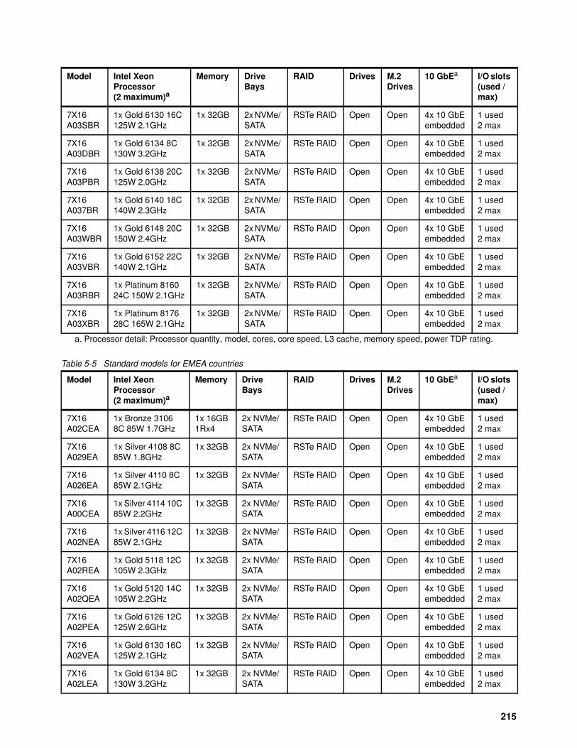
Table 5-5 Standard models for EMEA countries
7X16 A03SBR
1x Gold 6130 16C 125W 2.1GHz
1x 32GB 2x NVMe/ SATA
RSTe RAID Open Open 4x 10 GbEembedded
1 used2 max
7X16 A03DBR
1x Gold 6134 8C 130W 3.2GHz
1x 32GB 2x NVMe/ SATA
RSTe RAID Open Open 4x 10 GbEembedded
1 used2 max
7X16 A03PBR
1x Gold 6138 20C 125W 2.0GHz
1x 32GB 2x NVMe/ SATA
RSTe RAID Open Open 4x 10 GbEembedded
1 used2 max
7X16 A037BR
1x Gold 6140 18C 140W 2.3GHz
1x 32GB 2x NVMe/ SATA
RSTe RAID Open Open 4x 10 GbEembedded
1 used2 max
7X16 A03WBR
1x Gold 6148 20C 150W 2.4GHz
1x 32GB 2x NVMe/ SATA
RSTe RAID Open Open 4x 10 GbEembedded
1 used2 max
7X16 A03VBR
1x Gold 6152 22C 140W 2.1GHz
1x 32GB 2x NVMe/ SATA
RSTe RAID Open Open 4x 10 GbEembedded
1 used2 max
7X16 A03RBR
1x Platinum 8160 24C 150W 2.1GHz
1x 32GB 2x NVMe/ SATA
RSTe RAID Open Open 4x 10 GbEembedded
1 used2 max
7X16 A03XBR
1x Platinum 8176 28C 165W 2.1GHz
1x 32GB 2x NVMe/ SATA
RSTe RAID Open Open 4x 10 GbEembedded
1 used2 max
a. Processor detail: Processor quantity, model, cores, core speed, L3 cache, memory speed, power TDP rating.
Model Intel Xeon Processor (2 maximum)a
Memory Drive Bays
RAID Drives M.2Drives
10 GbEa I/O slots (used / max)
7X16 A02CEA
1x Bronze 3106 8C 85W 1.7GHz
1x 16GB 1Rx4
2x NVMe/ SATA
RSTe RAID Open Open 4x 10 GbEembedded
1 used2 max
7X16 A029EA
1x Silver 4108 8C 85W 1.8GHz
1x 32GB 2x NVMe/ SATA
RSTe RAID Open Open 4x 10 GbEembedded
1 used2 max
7X16 A026EA
1x Silver 4110 8C 85W 2.1GHz
1x 32GB 2x NVMe/ SATA
RSTe RAID Open Open 4x 10 GbEembedded
1 used2 max
7X16 A00CEA
1x Silver 4114 10C 85W 2.2GHz
1x 32GB 2x NVMe/ SATA
RSTe RAID Open Open 4x 10 GbEembedded
1 used2 max
7X16 A02NEA
1x Silver 4116 12C 85W 2.1GHz
1x 32GB 2x NVMe/ SATA
RSTe RAID Open Open 4x 10 GbEembedded
1 used2 max
7X16 A02REA
1x Gold 5118 12C 105W 2.3GHz
1x 32GB 2x NVMe/ SATA
RSTe RAID Open Open 4x 10 GbEembedded
1 used2 max
7X16 A02QEA
1x Gold 5120 14C 105W 2.2GHz
1x 32GB 2x NVMe/ SATA
RSTe RAID Open Open 4x 10 GbEembedded
1 used2 max
7X16 A02PEA
1x Gold 6126 12C 125W 2.6GHz
1x 32GB 2x NVMe/ SATA
RSTe RAID Open Open 4x 10 GbEembedded
1 used2 max
7X16 A02VEA
1x Gold 6130 16C 125W 2.1GHz
1x 32GB 2x NVMe/ SATA
RSTe RAID Open Open 4x 10 GbEembedded
1 used2 max
7X16 A02LEA
1x Gold 6134 8C 130W 3.2GHz
1x 32GB 2x NVMe/ SATA
RSTe RAID Open Open 4x 10 GbEembedded
1 used2 max
Model Intel Xeon Processor (2 maximum)a
Memory Drive Bays
RAID Drives M.2Drives
10 GbEa I/O slots (used / max)
215
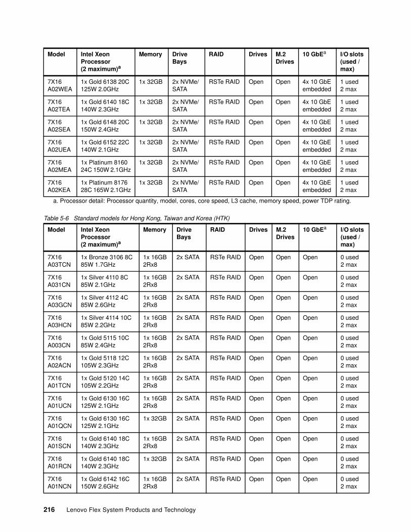
Table 5-6 Standard models for Hong Kong, Taiwan and Korea (HTK)
7X16 A02WEA
1x Gold 6138 20C 125W 2.0GHz
1x 32GB 2x NVMe/ SATA
RSTe RAID Open Open 4x 10 GbEembedded
1 used2 max
7X16 A02TEA
1x Gold 6140 18C 140W 2.3GHz
1x 32GB 2x NVMe/ SATA
RSTe RAID Open Open 4x 10 GbEembedded
1 used2 max
7X16 A02SEA
1x Gold 6148 20C 150W 2.4GHz
1x 32GB 2x NVMe/ SATA
RSTe RAID Open Open 4x 10 GbEembedded
1 used2 max
7X16 A02UEA
1x Gold 6152 22C 140W 2.1GHz
1x 32GB 2x NVMe/ SATA
RSTe RAID Open Open 4x 10 GbEembedded
1 used2 max
7X16 A02MEA
1x Platinum 8160 24C 150W 2.1GHz
1x 32GB 2x NVMe/ SATA
RSTe RAID Open Open 4x 10 GbEembedded
1 used2 max
7X16 A02KEA
1x Platinum 8176 28C 165W 2.1GHz
1x 32GB 2x NVMe/ SATA
RSTe RAID Open Open 4x 10 GbEembedded
1 used2 max
a. Processor detail: Processor quantity, model, cores, core speed, L3 cache, memory speed, power TDP rating.
Model Intel Xeon Processor (2 maximum)a
Memory Drive Bays
RAID Drives M.2Drives
10 GbEa I/O slots (used / max)
7X16 A03TCN
1x Bronze 3106 8C 85W 1.7GHz
1x 16GB 2Rx8
2x SATA RSTe RAID Open Open Open 0 used2 max
7X16 A031CN
1x Silver 4110 8C 85W 2.1GHz
1x 16GB 2Rx8
2x SATA RSTe RAID Open Open Open 0 used2 max
7X16 A03GCN
1x Silver 4112 4C 85W 2.6GHz
1x 16GB 2Rx8
2x SATA RSTe RAID Open Open Open 0 used2 max
7X16 A03HCN
1x Silver 4114 10C 85W 2.2GHz
1x 16GB 2Rx8
2x SATA RSTe RAID Open Open Open 0 used2 max
7X16 A003CN
1x Gold 5115 10C 85W 2.4GHz
1x 16GB 2Rx8
2x SATA RSTe RAID Open Open Open 0 used2 max
7X16 A02ACN
1x Gold 5118 12C 105W 2.3GHz
1x 16GB 2Rx8
2x SATA RSTe RAID Open Open Open 0 used2 max
7X16 A01TCN
1x Gold 5120 14C 105W 2.2GHz
1x 16GB 2Rx8
2x SATA RSTe RAID Open Open Open 0 used2 max
7X16 A01UCN
1x Gold 6130 16C 125W 2.1GHz
1x 16GB 2Rx8
2x SATA RSTe RAID Open Open Open 0 used2 max
7X16 A01QCN
1x Gold 6130 16C 125W 2.1GHz
1x 32GB 2x SATA RSTe RAID Open Open Open 0 used2 max
7X16 A01SCN
1x Gold 6140 18C 140W 2.3GHz
1x 16GB 2Rx8
2x SATA RSTe RAID Open Open Open 0 used2 max
7X16 A01RCN
1x Gold 6140 18C 140W 2.3GHz
1x 32GB 2x SATA RSTe RAID Open Open Open 0 used2 max
7X16 A01NCN
1x Gold 6142 16C 150W 2.6GHz
1x 16GB 2Rx8
2x SATA RSTe RAID Open Open Open 0 used2 max
Model Intel Xeon Processor (2 maximum)a
Memory Drive Bays
RAID Drives M.2Drives
10 GbEa I/O slots (used / max)
216 Lenovo Flex System Products and Technology

Table 5-7 Standard models for India
7X16 A01PCN
1x Gold 6142 16C 150W 2.6GHz
1x 32GB 2x SATA RSTe RAID Open Open Open 0 used2 max
7X16 A01LCN
1x Platinum 8160 24C 150W 2.1GHz
1x 16GB 2Rx8
2x SATA RSTe RAID Open Open Open 0 used2 max
7X16 A016CN
2x Platinum 8170 26C 165W 2.1GHz
1x 16GB 2Rx8
2x SATA RSTe RAID Open Open Open 0 used2 max
a. Processor detail: Processor quantity, model, cores, core speed, L3 cache, memory speed, power TDP rating.
Model Intel Xeon Processor (2 maximum)a
Memory Drive Bays
RAID Drives M.2Drives
10 GbEa I/O slots (used / max)
7X16 A00DSG
1x Silver 4116 12C 85W 2.1GHz
1x 16GB 1Rx4
2x SAS/ SATA
RAID 530-4i Open Open 4x 10 GbEembedded
1 used2 max
7X16 A00QSG
1x Silver 4116 12C 85W 2.1GHz
1x 16GB 1Rx4
2x SATA RSTe RAID Open Open 4x 10 GbEembedded
1 used2 max
7X16 A00HSG
1x Gold 5115 10C 85W 2.4GHz
1x 16GB 1Rx4
2x SATA RSTe RAID Open Open 4x 10 GbEembedded
1 used2 max
7X16 A00PSG
1x Gold 5115 10C 85W 2.4GHz
1x 16GB 1Rx4
2x SAS/ SATA
RAID 530-4i Open Open 4x 10 GbEembedded
1 used2 max
7X16 A00ESG
1x Gold 5118 12C 105W 2.3GHz
1x 16GB 1Rx4
2x SAS/ SATA
RAID 530-4i Open Open 4x 10 GbEembedded
1 used2 max
7X16 A00NSG
1x Gold 5118 12C 105W 2.3GHz
1x 16GB 1Rx4
2x SATA RSTe RAID Open Open 4x 10 GbEembedded
1 used2 max
7X16 A00KSG
1x Gold 5120 14C 105W 2.2GHz
1x 16GB 1Rx4
2x SATA RSTe RAID Open Open 4x 10 GbEembedded
1 used2 max
7X16 A00LSG
1x Gold 5120 14C 105W 2.2GHz
1x 16GB 1Rx4
2x SAS/ SATA
RAID 530-4i Open Open 4x 10 GbEembedded
1 used2 max
7X16 A00GSG
1x Gold 6126 12C 125W 2.6GHz
1x 16GB 1Rx4
2x SATA RSTe RAID Open Open 4x 10 GbEembedded
1 used2 max
7X16 A00VSG
1x Gold 6126 12C 125W 2.6GHz
1x 16GB 1Rx4
2x SAS/ SATA
RAID 530-4i Open Open 4x 10 GbEembedded
1 used2 max
7X16 A009SG
1x Gold 6130 16C 125W 2.1GHz
1x 16GB 1Rx4
2x SATA RSTe RAID Open Open 4x 10 GbEembedded
1 used2 max
7X16 A00ZSG
1x Gold 6130 16C 125W 2.1GHz
1x 16GB 1Rx4
2x SAS/ SATA
RAID 530-4i Open Open 4x 10 GbEembedded
1 used2 max
7X16 A004SG
1x Gold 6136 12C 150W 3.0GHz
1x 16GB 1Rx4
2x SAS/ SATA
RAID 530-4i Open Open 4x 10 GbEembedded
1 used2 max
7X16 A00SSG
1x Gold 6136 12C 150W 3.0GHz
1x 16GB 1Rx4
2x SATA RAID 530-4i Open Open 4x 10 GbEembedded
1 used2 max
7X16 A002SG
1x Gold 6140 18C 140W 2.3GHz
1x 16GB 1Rx4
2x SATA RSTe RAID Open Open 4x 10 GbEembedded
1 used2 max
Model Intel Xeon Processor (2 maximum)a
Memory Drive Bays
RAID Drives M.2Drives
10 GbEa I/O slots (used / max)
217
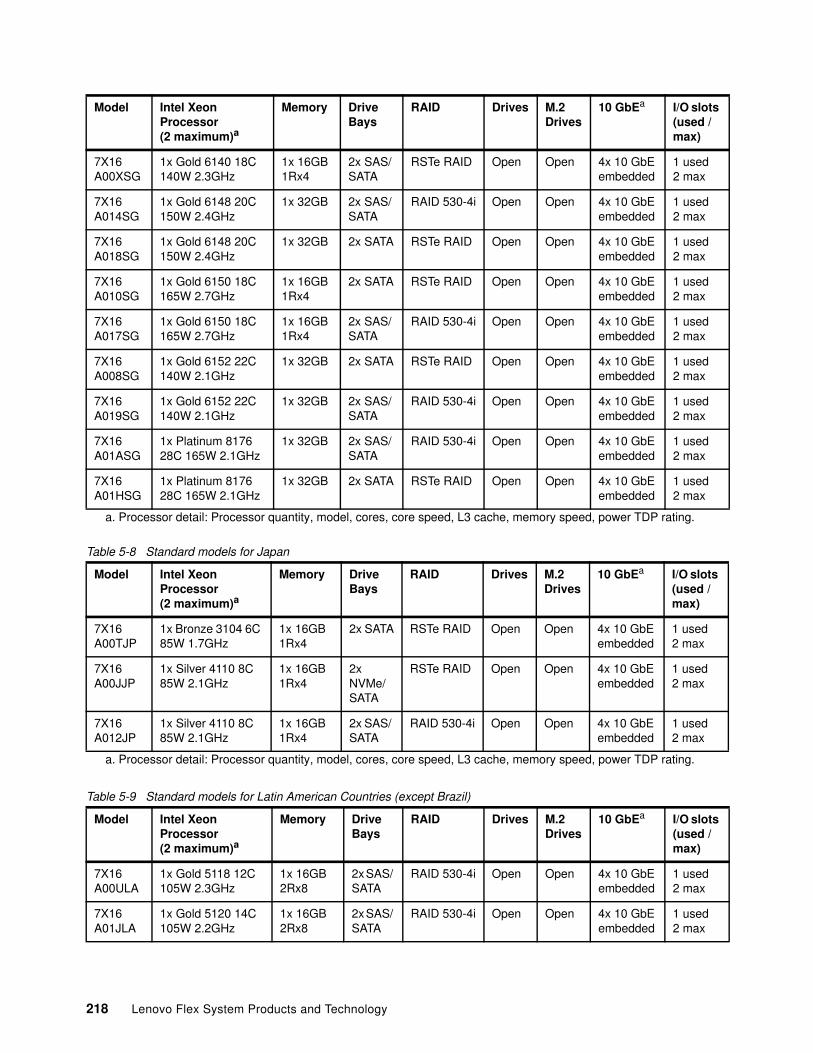
Table 5-8 Standard models for Japan
Table 5-9 Standard models for Latin American Countries (except Brazil)
7X16 A00XSG
1x Gold 6140 18C 140W 2.3GHz
1x 16GB 1Rx4
2x SAS/ SATA
RSTe RAID Open Open 4x 10 GbEembedded
1 used2 max
7X16 A014SG
1x Gold 6148 20C 150W 2.4GHz
1x 32GB 2x SAS/ SATA
RAID 530-4i Open Open 4x 10 GbEembedded
1 used2 max
7X16 A018SG
1x Gold 6148 20C 150W 2.4GHz
1x 32GB 2x SATA RSTe RAID Open Open 4x 10 GbEembedded
1 used2 max
7X16 A010SG
1x Gold 6150 18C 165W 2.7GHz
1x 16GB 1Rx4
2x SATA RSTe RAID Open Open 4x 10 GbEembedded
1 used2 max
7X16 A017SG
1x Gold 6150 18C 165W 2.7GHz
1x 16GB 1Rx4
2x SAS/ SATA
RAID 530-4i Open Open 4x 10 GbEembedded
1 used2 max
7X16 A008SG
1x Gold 6152 22C 140W 2.1GHz
1x 32GB 2x SATA RSTe RAID Open Open 4x 10 GbEembedded
1 used2 max
7X16 A019SG
1x Gold 6152 22C 140W 2.1GHz
1x 32GB 2x SAS/ SATA
RAID 530-4i Open Open 4x 10 GbEembedded
1 used2 max
7X16 A01ASG
1x Platinum 8176 28C 165W 2.1GHz
1x 32GB 2x SAS/ SATA
RAID 530-4i Open Open 4x 10 GbEembedded
1 used2 max
7X16 A01HSG
1x Platinum 8176 28C 165W 2.1GHz
1x 32GB 2x SATA RSTe RAID Open Open 4x 10 GbEembedded
1 used2 max
a. Processor detail: Processor quantity, model, cores, core speed, L3 cache, memory speed, power TDP rating.
Model Intel Xeon Processor (2 maximum)a
a. Processor detail: Processor quantity, model, cores, core speed, L3 cache, memory speed, power TDP rating.
Memory Drive Bays
RAID Drives M.2Drives
10 GbEa I/O slots (used / max)
7X16 A00TJP
1x Bronze 3104 6C 85W 1.7GHz
1x 16GB 1Rx4
2x SATA RSTe RAID Open Open 4x 10 GbEembedded
1 used2 max
7X16 A00JJP
1x Silver 4110 8C 85W 2.1GHz
1x 16GB 1Rx4
2x NVMe/ SATA
RSTe RAID Open Open 4x 10 GbEembedded
1 used2 max
7X16 A012JP
1x Silver 4110 8C 85W 2.1GHz
1x 16GB 1Rx4
2x SAS/ SATA
RAID 530-4i Open Open 4x 10 GbEembedded
1 used2 max
Model Intel Xeon Processor (2 maximum)a
Memory Drive Bays
RAID Drives M.2Drives
10 GbEa I/O slots (used / max)
7X16 A00ULA
1x Gold 5118 12C 105W 2.3GHz
1x 16GB 2Rx8
2x SAS/ SATA
RAID 530-4i Open Open 4x 10 GbEembedded
1 used2 max
7X16 A01JLA
1x Gold 5120 14C 105W 2.2GHz
1x 16GB 2Rx8
2x SAS/ SATA
RAID 530-4i Open Open 4x 10 GbEembedded
1 used2 max
Model Intel Xeon Processor (2 maximum)a
Memory Drive Bays
RAID Drives M.2Drives
10 GbEa I/O slots (used / max)
218 Lenovo Flex System Products and Technology
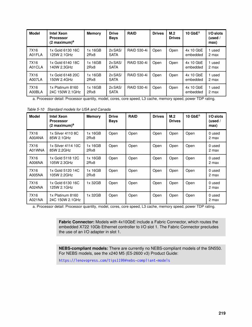
Table 5-10 Standard models for USA and Canada
7X16 A01FLA
1x Gold 6130 16C 125W 2.1GHz
1x 16GB 2Rx8
2x SAS/ SATA
RAID 530-4i Open Open 4x 10 GbEembedded
1 used2 max
7X16 A01CLA
1x Gold 6140 18C 140W 2.3GHz
1x 16GB 2Rx8
2x SAS/ SATA
RAID 530-4i Open Open 4x 10 GbEembedded
1 used2 max
7X16 A007LA
1x Gold 6148 20C 150W 2.4GHz
1x 16GB 2Rx8
2x SAS/ SATA
RAID 530-4i Open Open 4x 10 GbEembedded
1 used2 max
7X16 A00BLA
1x Platinum 8160 24C 150W 2.1GHz
1x 16GB 2Rx8
2x SAS/ SATA
RAID 530-4i Open Open 4x 10 GbEembedded
1 used2 max
a. Processor detail: Processor quantity, model, cores, core speed, L3 cache, memory speed, power TDP rating.
Model Intel Xeon Processor (2 maximum)a
a. Processor detail: Processor quantity, model, cores, core speed, L3 cache, memory speed, power TDP rating.
Memory Drive Bays
RAID Drives M.2Drives
10 GbEa I/O slots (used / max)
7X16 A00ANA
1x Silver 4110 8C 85W 2.1GHz
1x 16GB 2Rx8
Open Open Open Open Open 0 used2 max
7X16 A01WNA
1x Silver 4114 10C 85W 2.2GHz
1x 16GB 2Rx8
Open Open Open Open Open 0 used2 max
7X16 A006NA
1x Gold 5118 12C 105W 2.3GHz
1x 16GB 2Rx8
Open Open Open Open Open 0 used2 max
7X16 A005NA
1x Gold 5120 14C 105W 2.2GHz
1x 16GB 2Rx8
Open Open Open Open Open 0 used2 max
7X16 A024NA
1x Gold 6130 16C 125W 2.1GHz
1x 32GB Open Open Open Open Open 0 used2 max
7X16 A021NA
1x Platinum 8160 24C 150W 2.1GHz
1x 32GB Open Open Open Open Open 0 used2 max
Model Intel Xeon Processor (2 maximum)a
Memory Drive Bays
RAID Drives M.2Drives
10 GbEa I/O slots (used / max)
Fabric Connector: Models with 4x10GbE include a Fabric Connector, which routes the embedded X722 10Gb Ethernet controller to I/O slot 1. The Fabric Connector precludes the use of an I/O adapter in slot 1.
NEBS-compliant models: There are currently no NEBS-compliant models of the SN550. For NEBS models, see the x240 M5 (E5-2600 v3) Product Guide:
https://lenovopress.com/tips1199#nebs-compliant-models
219
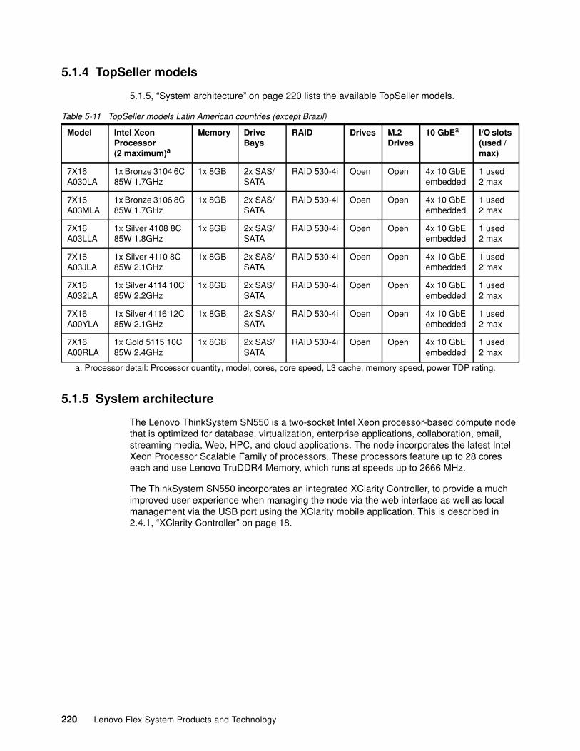
5.1.4 TopSeller models
5.1.5, “System architecture” on page 220 lists the available TopSeller models.
Table 5-11 TopSeller models Latin American countries (except Brazil)
5.1.5 System architecture
The Lenovo ThinkSystem SN550 is a two-socket Intel Xeon processor-based compute node that is optimized for database, virtualization, enterprise applications, collaboration, email, streaming media, Web, HPC, and cloud applications. The node incorporates the latest Intel Xeon Processor Scalable Family of processors. These processors feature up to 28 cores each and use Lenovo TruDDR4 Memory, which runs at speeds up to 2666 MHz.
The ThinkSystem SN550 incorporates an integrated XClarity Controller, to provide a much improved user experience when managing the node via the web interface as well as local management via the USB port using the XClarity mobile application. This is described in 2.4.1, “XClarity Controller” on page 18.
Model Intel Xeon Processor (2 maximum)a
a. Processor detail: Processor quantity, model, cores, core speed, L3 cache, memory speed, power TDP rating.
Memory Drive Bays
RAID Drives M.2Drives
10 GbEa I/O slots (used / max)
7X16 A030LA
1x Bronze 3104 6C 85W 1.7GHz
1x 8GB 2x SAS/ SATA
RAID 530-4i Open Open 4x 10 GbEembedded
1 used2 max
7X16 A03MLA
1x Bronze 3106 8C 85W 1.7GHz
1x 8GB 2x SAS/ SATA
RAID 530-4i Open Open 4x 10 GbEembedded
1 used2 max
7X16 A03LLA
1x Silver 4108 8C 85W 1.8GHz
1x 8GB 2x SAS/ SATA
RAID 530-4i Open Open 4x 10 GbEembedded
1 used2 max
7X16 A03JLA
1x Silver 4110 8C 85W 2.1GHz
1x 8GB 2x SAS/ SATA
RAID 530-4i Open Open 4x 10 GbEembedded
1 used2 max
7X16 A032LA
1x Silver 4114 10C 85W 2.2GHz
1x 8GB 2x SAS/ SATA
RAID 530-4i Open Open 4x 10 GbEembedded
1 used2 max
7X16 A00YLA
1x Silver 4116 12C 85W 2.1GHz
1x 8GB 2x SAS/ SATA
RAID 530-4i Open Open 4x 10 GbEembedded
1 used2 max
7X16 A00RLA
1x Gold 5115 10C 85W 2.4GHz
1x 8GB 2x SAS/ SATA
RAID 530-4i Open Open 4x 10 GbEembedded
1 used2 max
220 Lenovo Flex System Products and Technology
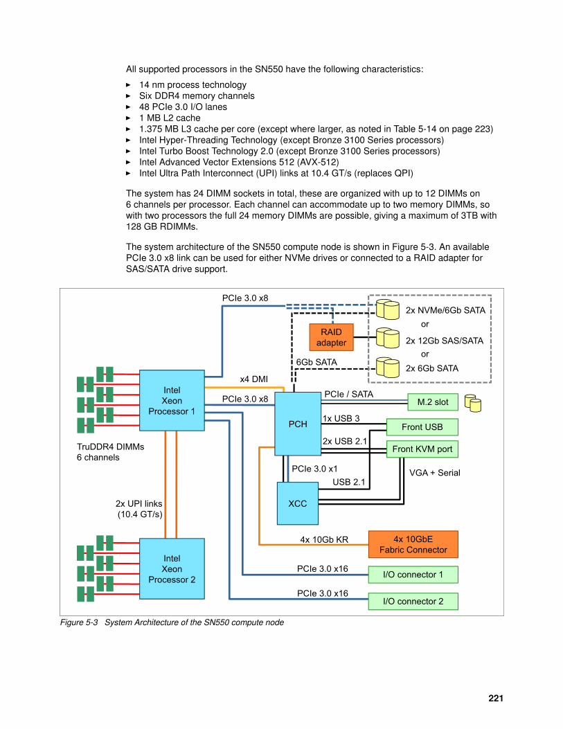
All supported processors in the SN550 have the following characteristics:
� 14 nm process technology� Six DDR4 memory channels� 48 PCIe 3.0 I/O lanes� 1 MB L2 cache� 1.375 MB L3 cache per core (except where larger, as noted in Table 5-14 on page 223)� Intel Hyper-Threading Technology (except Bronze 3100 Series processors)� Intel Turbo Boost Technology 2.0 (except Bronze 3100 Series processors)� Intel Advanced Vector Extensions 512 (AVX-512)� Intel Ultra Path Interconnect (UPI) links at 10.4 GT/s (replaces QPI)
The system has 24 DIMM sockets in total, these are organized with up to 12 DIMMs on 6 channels per processor. Each channel can accommodate up to two memory DIMMs, so with two processors the full 24 memory DIMMs are possible, giving a maximum of 3TB with 128 GB RDIMMs.
The system architecture of the SN550 compute node is shown in Figure 5-3. An available PCIe 3.0 x8 link can be used for either NVMe drives or connected to a RAID adapter for SAS/SATA drive support.
Figure 5-3 System Architecture of the SN550 compute node
2x UPI links(10.4 GT/s)
x4 DMI
I/O connector 1
I/O connector 2PCIe 3.0 x16
PCIe 3.0 x16
TruDDR4 DIMMs6 channels
2x USB 2.1
1x USB 3
PCIe 3.0 x1USB 2.1
VGA + Serial
4x 10Gb KR
PCIe 3.0 x8
6Gb SATA
PCIe 3.0 x8
Front KVM port
XCC
Front USB
IntelXeon
Processor 2
4x 10GbE Fabric Connector
or
or2x 6Gb SATA
2x 12Gb SAS/SATARAID
adapter
2x NVMe/6Gb SATA
IntelXeon
Processor 1PCH
M.2 slotPCIe / SATA
221
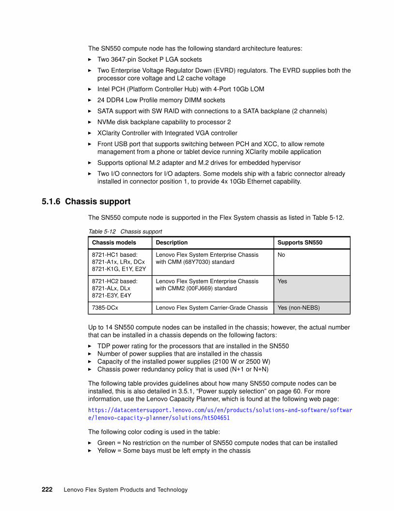
The SN550 compute node has the following standard architecture features:
� Two 3647-pin Socket P LGA sockets
� Two Enterprise Voltage Regulator Down (EVRD) regulators. The EVRD supplies both the processor core voltage and L2 cache voltage
� Intel PCH (Platform Controller Hub) with 4-Port 10Gb LOM
� 24 DDR4 Low Profile memory DIMM sockets
� SATA support with SW RAID with connections to a SATA backplane (2 channels)
� NVMe disk backplane capability to processor 2
� XClarity Controller with Integrated VGA controller
� Front USB port that supports switching between PCH and XCC, to allow remote management from a phone or tablet device running XClarity mobile application
� Supports optional M.2 adapter and M.2 drives for embedded hypervisor
� Two I/O connectors for I/O adapters. Some models ship with a fabric connector already installed in connector position 1, to provide 4x 10Gb Ethernet capability.
5.1.6 Chassis support
The SN550 compute node is supported in the Flex System chassis as listed in Table 5-12.
Table 5-12 Chassis support
Up to 14 SN550 compute nodes can be installed in the chassis; however, the actual number that can be installed in a chassis depends on the following factors:
� TDP power rating for the processors that are installed in the SN550� Number of power supplies that are installed in the chassis� Capacity of the installed power supplies (2100 W or 2500 W)� Chassis power redundancy policy that is used (N+1 or N+N)
The following table provides guidelines about how many SN550 compute nodes can be installed, this is also detailed in 3.5.1, “Power supply selection” on page 60. For more information, use the Lenovo Capacity Planner, which is found at the following web page:
https://datacentersupport.lenovo.com/us/en/products/solutions-and-software/software/lenovo-capacity-planner/solutions/ht504651
The following color coding is used in the table:
� Green = No restriction on the number of SN550 compute nodes that can be installed� Yellow = Some bays must be left empty in the chassis
Chassis models Description Supports SN550
8721-HC1 based:8721-A1x, LRx, DCx8721-K1G, E1Y, E2Y
Lenovo Flex System Enterprise Chassiswith CMM (68Y7030) standard
No
8721-HC2 based:8721-ALx, DLx8721-E3Y, E4Y
Lenovo Flex System Enterprise Chassiswith CMM2 (00FJ669) standard
Yes
7385-DCx Lenovo Flex System Carrier-Grade Chassis Yes (non-NEBS)
222 Lenovo Flex System Products and Technology
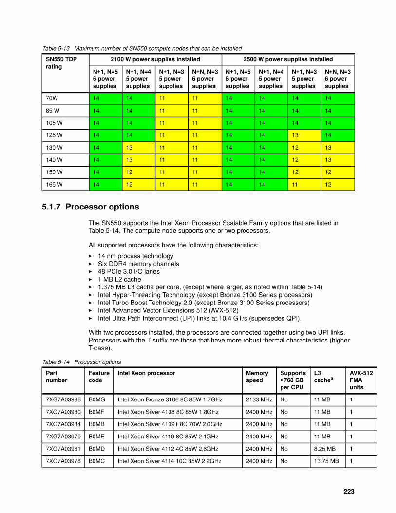
-512
s
Table 5-13 Maximum number of SN550 compute nodes that can be installed
5.1.7 Processor options
The SN550 supports the Intel Xeon Processor Scalable Family options that are listed in Table 5-14. The compute node supports one or two processors.
All supported processors have the following characteristics:
� 14 nm process technology� Six DDR4 memory channels� 48 PCIe 3.0 I/O lanes� 1 MB L2 cache� 1.375 MB L3 cache per core, (except where larger, as noted within Table 5-14)� Intel Hyper-Threading Technology (except Bronze 3100 Series processors)� Intel Turbo Boost Technology 2.0 (except Bronze 3100 Series processors)� Intel Advanced Vector Extensions 512 (AVX-512)� Intel Ultra Path Interconnect (UPI) links at 10.4 GT/s (supersedes QPI).
With two processors installed, the processors are connected together using two UPI links. Processors with the T suffix are those that have more robust thermal characteristics (higher T-case).
Table 5-14 Processor options
SN550 TDP rating
2100 W power supplies installed 2500 W power supplies installed
N+1, N=56 powersupplies
N+1, N=45 powersupplies
N+1, N=35 powersupplies
N+N, N=36 powersupplies
N+1, N=56 powersupplies
N+1, N=45 powersupplies
N+1, N=35 powersupplies
N+N, N=36 powersupplies
70W 14 14 11 11 14 14 14 14
85 W 14 14 11 11 14 14 14 14
105 W 14 14 11 11 14 14 14 14
125 W 14 14 11 11 14 14 13 14
130 W 14 13 11 11 14 14 12 13
140 W 14 13 11 11 14 14 12 13
150 W 14 12 11 11 14 14 12 12
165 W 14 12 11 11 14 14 11 12
Partnumber
Featurecode
Intel Xeon processor Memoryspeed
Supports>768 GBper CPU
L3cachea
AVXFMAunit
7XG7A03985 B0MG Intel Xeon Bronze 3106 8C 85W 1.7GHz 2133 MHz No 11 MB 1
7XG7A03980 B0MF Intel Xeon Silver 4108 8C 85W 1.8GHz 2400 MHz No 11 MB 1
7XG7A03984 B0MB Intel Xeon Silver 4109T 8C 70W 2.0GHz 2400 MHz No 11 MB 1
7XG7A03979 B0ME Intel Xeon Silver 4110 8C 85W 2.1GHz 2400 MHz No 11 MB 1
7XG7A03981 B0MD Intel Xeon Silver 4112 4C 85W 2.6GHz 2400 MHz No 8.25 MB 1
7XG7A03978 B0MC Intel Xeon Silver 4114 10C 85W 2.2GHz 2400 MHz No 13.75 MB 1
223
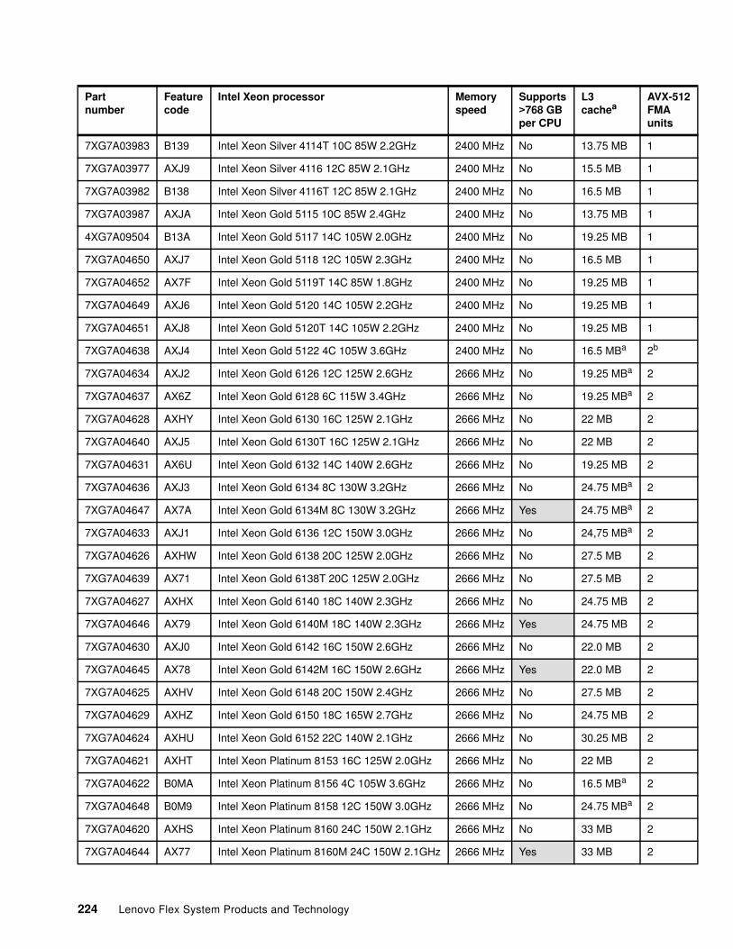
-512
s
7XG7A03983 B139 Intel Xeon Silver 4114T 10C 85W 2.2GHz 2400 MHz No 13.75 MB 1
7XG7A03977 AXJ9 Intel Xeon Silver 4116 12C 85W 2.1GHz 2400 MHz No 15.5 MB 1
7XG7A03982 B138 Intel Xeon Silver 4116T 12C 85W 2.1GHz 2400 MHz No 16.5 MB 1
7XG7A03987 AXJA Intel Xeon Gold 5115 10C 85W 2.4GHz 2400 MHz No 13.75 MB 1
4XG7A09504 B13A Intel Xeon Gold 5117 14C 105W 2.0GHz 2400 MHz No 19.25 MB 1
7XG7A04650 AXJ7 Intel Xeon Gold 5118 12C 105W 2.3GHz 2400 MHz No 16.5 MB 1
7XG7A04652 AX7F Intel Xeon Gold 5119T 14C 85W 1.8GHz 2400 MHz No 19.25 MB 1
7XG7A04649 AXJ6 Intel Xeon Gold 5120 14C 105W 2.2GHz 2400 MHz No 19.25 MB 1
7XG7A04651 AXJ8 Intel Xeon Gold 5120T 14C 105W 2.2GHz 2400 MHz No 19.25 MB 1
7XG7A04638 AXJ4 Intel Xeon Gold 5122 4C 105W 3.6GHz 2400 MHz No 16.5 MBa 2b
7XG7A04634 AXJ2 Intel Xeon Gold 6126 12C 125W 2.6GHz 2666 MHz No 19.25 MBa 2
7XG7A04637 AX6Z Intel Xeon Gold 6128 6C 115W 3.4GHz 2666 MHz No 19.25 MBa 2
7XG7A04628 AXHY Intel Xeon Gold 6130 16C 125W 2.1GHz 2666 MHz No 22 MB 2
7XG7A04640 AXJ5 Intel Xeon Gold 6130T 16C 125W 2.1GHz 2666 MHz No 22 MB 2
7XG7A04631 AX6U Intel Xeon Gold 6132 14C 140W 2.6GHz 2666 MHz No 19.25 MB 2
7XG7A04636 AXJ3 Intel Xeon Gold 6134 8C 130W 3.2GHz 2666 MHz No 24.75 MBa 2
7XG7A04647 AX7A Intel Xeon Gold 6134M 8C 130W 3.2GHz 2666 MHz Yes 24.75 MBa 2
7XG7A04633 AXJ1 Intel Xeon Gold 6136 12C 150W 3.0GHz 2666 MHz No 24,75 MBa 2
7XG7A04626 AXHW Intel Xeon Gold 6138 20C 125W 2.0GHz 2666 MHz No 27.5 MB 2
7XG7A04639 AX71 Intel Xeon Gold 6138T 20C 125W 2.0GHz 2666 MHz No 27.5 MB 2
7XG7A04627 AXHX Intel Xeon Gold 6140 18C 140W 2.3GHz 2666 MHz No 24.75 MB 2
7XG7A04646 AX79 Intel Xeon Gold 6140M 18C 140W 2.3GHz 2666 MHz Yes 24.75 MB 2
7XG7A04630 AXJ0 Intel Xeon Gold 6142 16C 150W 2.6GHz 2666 MHz No 22.0 MB 2
7XG7A04645 AX78 Intel Xeon Gold 6142M 16C 150W 2.6GHz 2666 MHz Yes 22.0 MB 2
7XG7A04625 AXHV Intel Xeon Gold 6148 20C 150W 2.4GHz 2666 MHz No 27.5 MB 2
7XG7A04629 AXHZ Intel Xeon Gold 6150 18C 165W 2.7GHz 2666 MHz No 24.75 MB 2
7XG7A04624 AXHU Intel Xeon Gold 6152 22C 140W 2.1GHz 2666 MHz No 30.25 MB 2
7XG7A04621 AXHT Intel Xeon Platinum 8153 16C 125W 2.0GHz 2666 MHz No 22 MB 2
7XG7A04622 B0MA Intel Xeon Platinum 8156 4C 105W 3.6GHz 2666 MHz No 16.5 MBa 2
7XG7A04648 B0M9 Intel Xeon Platinum 8158 12C 150W 3.0GHz 2666 MHz No 24.75 MBa 2
7XG7A04620 AXHS Intel Xeon Platinum 8160 24C 150W 2.1GHz 2666 MHz No 33 MB 2
7XG7A04644 AX77 Intel Xeon Platinum 8160M 24C 150W 2.1GHz 2666 MHz Yes 33 MB 2
Partnumber
Featurecode
Intel Xeon processor Memoryspeed
Supports>768 GBper CPU
L3cachea
AVXFMAunit
224 Lenovo Flex System Products and Technology
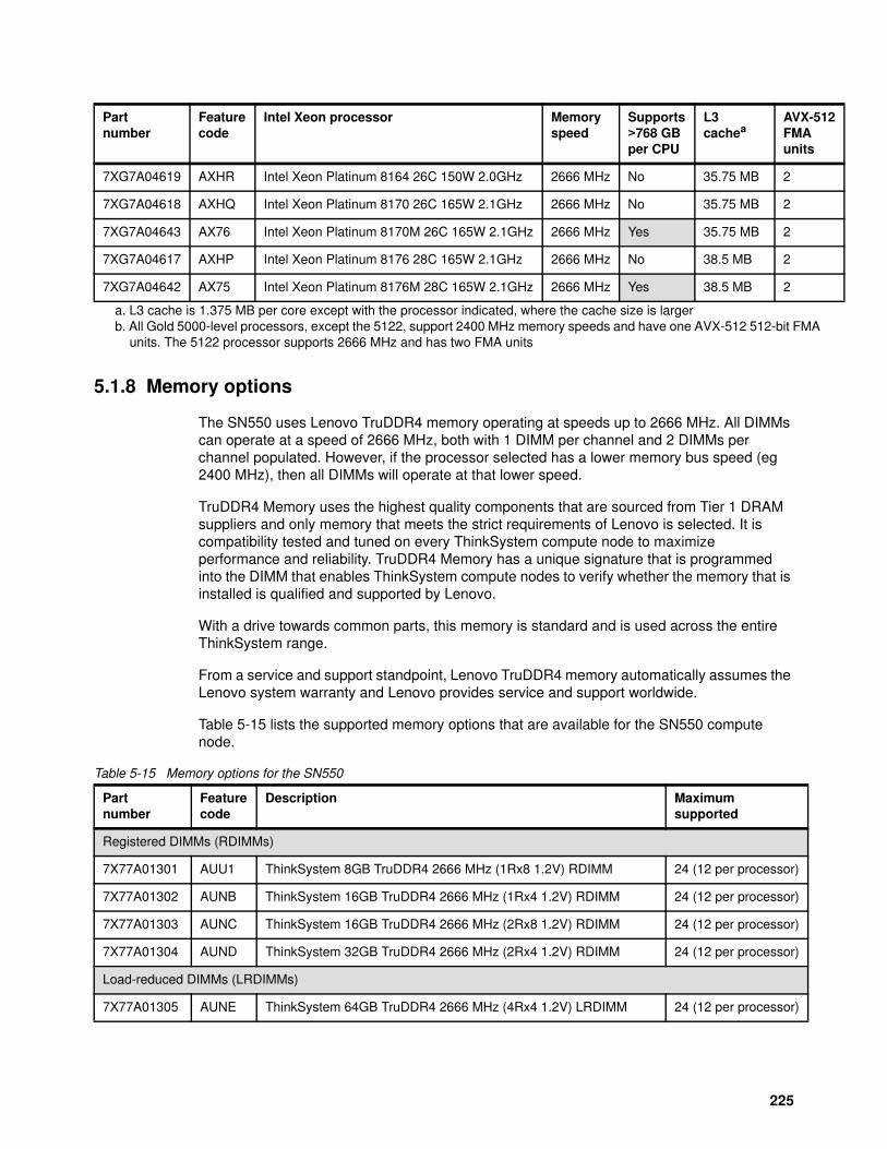
A
-512
s
5.1.8 Memory options
The SN550 uses Lenovo TruDDR4 memory operating at speeds up to 2666 MHz. All DIMMs can operate at a speed of 2666 MHz, both with 1 DIMM per channel and 2 DIMMs per channel populated. However, if the processor selected has a lower memory bus speed (eg 2400 MHz), then all DIMMs will operate at that lower speed.
TruDDR4 Memory uses the highest quality components that are sourced from Tier 1 DRAM suppliers and only memory that meets the strict requirements of Lenovo is selected. It is compatibility tested and tuned on every ThinkSystem compute node to maximize performance and reliability. TruDDR4 Memory has a unique signature that is programmed into the DIMM that enables ThinkSystem compute nodes to verify whether the memory that is installed is qualified and supported by Lenovo.
With a drive towards common parts, this memory is standard and is used across the entire ThinkSystem range.
From a service and support standpoint, Lenovo TruDDR4 memory automatically assumes the Lenovo system warranty and Lenovo provides service and support worldwide.
Table 5-15 lists the supported memory options that are available for the SN550 compute node.
Table 5-15 Memory options for the SN550
7XG7A04619 AXHR Intel Xeon Platinum 8164 26C 150W 2.0GHz 2666 MHz No 35.75 MB 2
7XG7A04618 AXHQ Intel Xeon Platinum 8170 26C 165W 2.1GHz 2666 MHz No 35.75 MB 2
7XG7A04643 AX76 Intel Xeon Platinum 8170M 26C 165W 2.1GHz 2666 MHz Yes 35.75 MB 2
7XG7A04617 AXHP Intel Xeon Platinum 8176 28C 165W 2.1GHz 2666 MHz No 38.5 MB 2
7XG7A04642 AX75 Intel Xeon Platinum 8176M 28C 165W 2.1GHz 2666 MHz Yes 38.5 MB 2
a. L3 cache is 1.375 MB per core except with the processor indicated, where the cache size is largerb. All Gold 5000-level processors, except the 5122, support 2400 MHz memory speeds and have one AVX-512 512-bit FM
units. The 5122 processor supports 2666 MHz and has two FMA units
Partnumber
Featurecode
Intel Xeon processor Memoryspeed
Supports>768 GBper CPU
L3cachea
AVXFMAunit
Partnumber
Featurecode
Description Maximumsupported
Registered DIMMs (RDIMMs)
7X77A01301 AUU1 ThinkSystem 8GB TruDDR4 2666 MHz (1Rx8 1.2V) RDIMM 24 (12 per processor)
7X77A01302 AUNB ThinkSystem 16GB TruDDR4 2666 MHz (1Rx4 1.2V) RDIMM 24 (12 per processor)
7X77A01303 AUNC ThinkSystem 16GB TruDDR4 2666 MHz (2Rx8 1.2V) RDIMM 24 (12 per processor)
7X77A01304 AUND ThinkSystem 32GB TruDDR4 2666 MHz (2Rx4 1.2V) RDIMM 24 (12 per processor)
Load-reduced DIMMs (LRDIMMs)
7X77A01305 AUNE ThinkSystem 64GB TruDDR4 2666 MHz (4Rx4 1.2V) LRDIMM 24 (12 per processor)
225
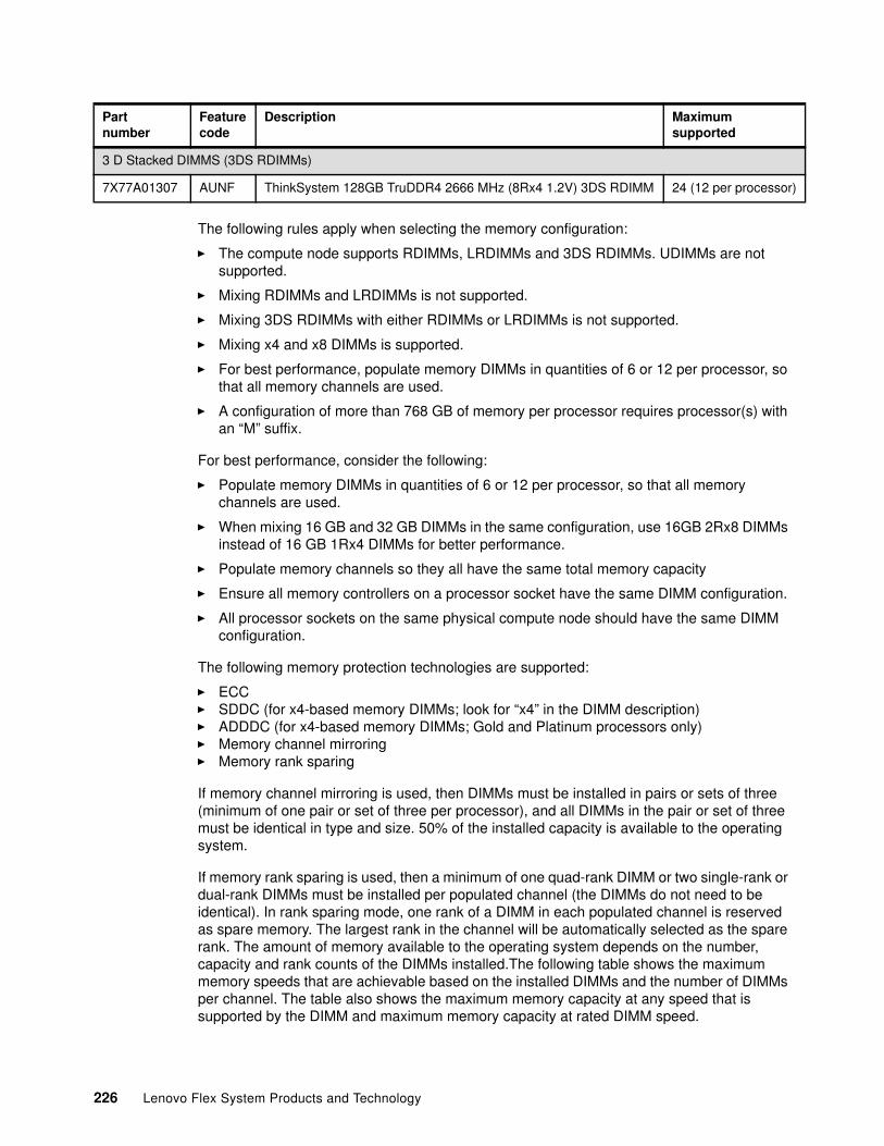
The following rules apply when selecting the memory configuration:
� The compute node supports RDIMMs, LRDIMMs and 3DS RDIMMs. UDIMMs are not supported.
� Mixing RDIMMs and LRDIMMs is not supported.
� Mixing 3DS RDIMMs with either RDIMMs or LRDIMMs is not supported.
� Mixing x4 and x8 DIMMs is supported.
� For best performance, populate memory DIMMs in quantities of 6 or 12 per processor, so that all memory channels are used.
� A configuration of more than 768 GB of memory per processor requires processor(s) with an “M” suffix.
For best performance, consider the following:
� Populate memory DIMMs in quantities of 6 or 12 per processor, so that all memory channels are used.
� When mixing 16 GB and 32 GB DIMMs in the same configuration, use 16GB 2Rx8 DIMMs instead of 16 GB 1Rx4 DIMMs for better performance.
� Populate memory channels so they all have the same total memory capacity
� Ensure all memory controllers on a processor socket have the same DIMM configuration.
� All processor sockets on the same physical compute node should have the same DIMM configuration.
The following memory protection technologies are supported:
� ECC� SDDC (for x4-based memory DIMMs; look for “x4” in the DIMM description)� ADDDC (for x4-based memory DIMMs; Gold and Platinum processors only)� Memory channel mirroring� Memory rank sparing
If memory channel mirroring is used, then DIMMs must be installed in pairs or sets of three (minimum of one pair or set of three per processor), and all DIMMs in the pair or set of three must be identical in type and size. 50% of the installed capacity is available to the operating system.
If memory rank sparing is used, then a minimum of one quad-rank DIMM or two single-rank or dual-rank DIMMs must be installed per populated channel (the DIMMs do not need to be identical). In rank sparing mode, one rank of a DIMM in each populated channel is reserved as spare memory. The largest rank in the channel will be automatically selected as the spare rank. The amount of memory available to the operating system depends on the number, capacity and rank counts of the DIMMs installed.The following table shows the maximum memory speeds that are achievable based on the installed DIMMs and the number of DIMMs per channel. The table also shows the maximum memory capacity at any speed that is supported by the DIMM and maximum memory capacity at rated DIMM speed.
3 D Stacked DIMMS (3DS RDIMMs)
7X77A01307 AUNF ThinkSystem 128GB TruDDR4 2666 MHz (8Rx4 1.2V) 3DS RDIMM 24 (12 per processor)
Partnumber
Featurecode
Description Maximumsupported
226 Lenovo Flex System Products and Technology
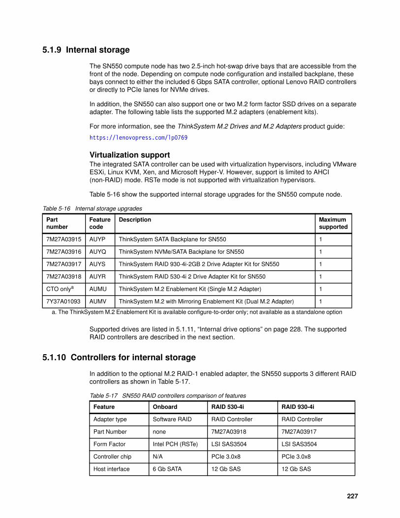
5.1.9 Internal storage
The SN550 compute node has two 2.5-inch hot-swap drive bays that are accessible from the front of the node. Depending on compute node configuration and installed backplane, these bays connect to either the included 6 Gbps SATA controller, optional Lenovo RAID controllers or directly to PCIe lanes for NVMe drives.
In addition, the SN550 can also support one or two M.2 form factor SSD drives on a separate adapter. The following table lists the supported M.2 adapters (enablement kits).
For more information, see the ThinkSystem M.2 Drives and M.2 Adapters product guide:
https://lenovopress.com/lp0769
Virtualization supportThe integrated SATA controller can be used with virtualization hypervisors, including VMware ESXi, Linux KVM, Xen, and Microsoft Hyper-V. However, support is limited to AHCI (non-RAID) mode. RSTe mode is not supported with virtualization hypervisors.
Table 5-16 show the supported internal storage upgrades for the SN550 compute node.
Table 5-16 Internal storage upgrades
Supported drives are listed in 5.1.11, “Internal drive options” on page 228. The supported RAID controllers are described in the next section.
5.1.10 Controllers for internal storage
In addition to the optional M.2 RAID-1 enabled adapter, the SN550 supports 3 different RAID controllers as shown in Table 5-17.
Table 5-17 SN550 RAID controllers comparison of features
Partnumber
Featurecode
Description Maximumsupported
7M27A03915 AUYP ThinkSystem SATA Backplane for SN550 1
7M27A03916 AUYQ ThinkSystem NVMe/SATA Backplane for SN550 1
7M27A03917 AUYS ThinkSystem RAID 930-4i-2GB 2 Drive Adapter Kit for SN550 1
7M27A03918 AUYR ThinkSystem RAID 530-4i 2 Drive Adapter Kit for SN550 1
CTO onlya
a. The ThinkSystem M.2 Enablement Kit is available configure-to-order only; not available as a standalone option
AUMU ThinkSystem M.2 Enablement Kit (Single M.2 Adapter) 1
7Y37A01093 AUMV ThinkSystem M.2 with Mirroring Enablement Kit (Dual M.2 Adapter) 1
Feature Onboard RAID 530-4i RAID 930-4i
Adapter type Software RAID RAID Controller RAID Controller
Part Number none 7M27A03918 7M27A03917
Form Factor Intel PCH (RSTe) LSI SAS3504 LSI SAS3504
Controller chip N/A PCIe 3.0x8 PCIe 3.0x8
Host interface 6 Gb SATA 12 Gb SAS 12 Gb SAS
227
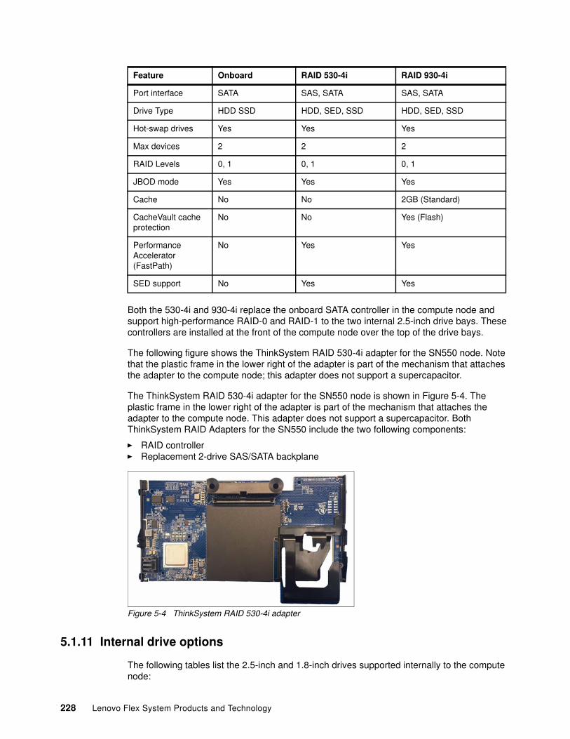
Both the 530-4i and 930-4i replace the onboard SATA controller in the compute node and support high-performance RAID-0 and RAID-1 to the two internal 2.5-inch drive bays. These controllers are installed at the front of the compute node over the top of the drive bays.
The following figure shows the ThinkSystem RAID 530-4i adapter for the SN550 node. Note that the plastic frame in the lower right of the adapter is part of the mechanism that attaches the adapter to the compute node; this adapter does not support a supercapacitor.
The ThinkSystem RAID 530-4i adapter for the SN550 node is shown in Figure 5-4. The plastic frame in the lower right of the adapter is part of the mechanism that attaches the adapter to the compute node. This adapter does not support a supercapacitor. Both ThinkSystem RAID Adapters for the SN550 include the two following components:
� RAID controller� Replacement 2-drive SAS/SATA backplane
Figure 5-4 ThinkSystem RAID 530-4i adapter
5.1.11 Internal drive options
The following tables list the 2.5-inch and 1.8-inch drives supported internally to the compute node:
Port interface SATA SAS, SATA SAS, SATA
Drive Type HDD SSD HDD, SED, SSD HDD, SED, SSD
Hot-swap drives Yes Yes Yes
Max devices 2 2 2
RAID Levels 0, 1 0, 1 0, 1
JBOD mode Yes Yes Yes
Cache No No 2GB (Standard)
CacheVault cache protection
No No Yes (Flash)
Performance Accelerator (FastPath)
No Yes Yes
SED support No Yes Yes
Feature Onboard RAID 530-4i RAID 930-4i
228 Lenovo Flex System Products and Technology
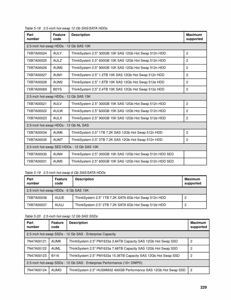
Table 5-18 2.5-inch hot-swap 12 Gb SAS/SATA HDDs
Table 5-19 2.5-inch hot-swap 6 Gb SAS/SATA HDDs
Table 5-20 2.5-inch hot-swap 12 Gb SAS SSDs
Partnumber
Featurecode
Description Maximumsupported
2.5-inch hot-swap HDDs - 12 Gb SAS 10K
7XB7A00024 AULY ThinkSystem 2.5" 300GB 10K SAS 12Gb Hot Swap 512n HDD 2
7XB7A00025 AULZ ThinkSystem 2.5" 600GB 10K SAS 12Gb Hot Swap 512n HDD 2
7XB7A00026 AUM0 ThinkSystem 2.5" 900GB 10K SAS 12Gb Hot Swap 512n HDD 2
7XB7A00027 AUM1 ThinkSystem 2.5" 1.2TB 10K SAS 12Gb Hot Swap 512n HDD 2
7XB7A00028 AUM2 ThinkSystem 2.5" 1.8TB 10K SAS 12Gb Hot Swap 512e HDD 2
7XB7A00069 B0YS ThinkSystem 2.5" 2.4TB 10K SAS 12Gb Hot Swap 512e HDD 2
2.5-inch hot-swap HDDs - 12 Gb SAS 15K
7XB7A00021 AULV ThinkSystem 2.5" 300GB 15K SAS 12Gb Hot Swap 512n HDD 2
7XB7A00022 AULW ThinkSystem 2.5" 600GB 15K SAS 12Gb Hot Swap 512n HDD 2
7XB7A00023 AULX ThinkSystem 2.5" 900GB 15K SAS 12Gb Hot Swap 512e HDD 2
2.5-inch hot-swap HDDs - 12 Gb NL SAS
7XB7A00034 AUM6 ThinkSystem 2.5" 1TB 7.2K SAS 12Gb Hot Swap 512n HDD 2
7XB7A00035 AUM7 ThinkSystem 2.5" 2TB 7.2K SAS 12Gb Hot Swap 512n HDD 2
2.5-inch hot-swap SED HDDs - 12 Gb SAS 10K
7XB7A00030 AUM4 ThinkSystem 2.5" 300GB 10K SAS 12Gb Hot Swap 512n HDD SED
7XB7A00031 AUM5 ThinkSystem 2.5" 600GB 10K SAS 12Gb Hot Swap 512n HDD SED
Partnumber
Feature code
Description Maximumsupported
2.5-inch hot-swap HDDs - 6 Gb SAS 15K
7XB7A00036 AUUE ThinkSystem 2.5" 1TB 7.2K SATA 6Gb Hot Swap 512n HDD 2
7XB7A00037 AUUJ ThinkSystem 2.5" 2TB 7.2K SATA 6Gb Hot Swap 512e HDD 2
Partnumber
Feature code
Description Maximumsupported
2.5-inch hot-swap SSDs - 12 Gb SAS - Enterprise Capacity
7N47A00121 AUMK ThinkSystem 2.5" PM1633a 3.84TB Capacity SAS 12Gb Hot Swap SSD 2
7N47A00122 AUML ThinkSystem 2.5" PM1633a 7.68TB Capacity SAS 12Gb Hot Swap SSD 2
7N47A00123 B116 ThinkSystem 2.5" PM1633a 15.36TB Capacity SAS 12Gb Hot Swap SSD 2
2.5-inch hot-swap SSDs - 12 Gb SAS - Enterprise Performance (10+ DWPD)
7N47A00124 AUMG ThinkSystem 2.5" HUSMM32 400GB Performance SAS 12Gb Hot Swap SSD 2
229
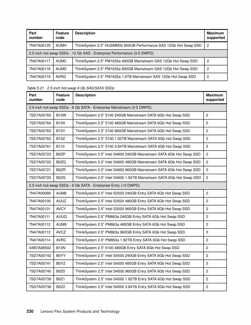
Table 5-21 2.5-inch hot-swap 6 Gb SAS/SATA SSDs
7N47A00125 AUMH ThinkSystem 2.5" HUSMM32 800GB Performance SAS 12Gb Hot Swap SSD 2
2.5-inch hot-swap SSDs - 12 Gb SAS - Enterprise Performance (3-5 DWPD)
7N47A00117 AUMC ThinkSystem 2.5" PM1635a 400GB Mainstream SAS 12Gb Hot Swap SSD 2
7N47A00118 AUMD ThinkSystem 2.5" PM1635a 800GB Mainstream SAS 12Gb Hot Swap SSD 2
7N47A00119 AVRG ThinkSystem 2.5" PM1635a 1.6TB Mainstream SAS 12Gb Hot Swap SSD 2
Partnumber
Feature code
Description Maximumsupported
2.5-inch hot-swap SSDs - 6 Gb SATA - Enterprise Mainstream (3-5 DWPD)
7SD7A05765 B10W ThinkSystem 2.5" 5100 240GB Mainstream SATA 6Gb Hot Swap SSD 2
7SD7A05764 B10X ThinkSystem 2.5" 5100 480GB Mainstream SATA 6Gb Hot Swap SSD 2
7SD7A05763 B10Y ThinkSystem 2.5" 5100 960GB Mainstream SATA 6Gb Hot Swap SSD 2
7SD7A05762 B10Z ThinkSystem 2.5" 5100 1.92TB Mainstream SATA 6Gb Hot Swap SSD 2
7SD7A05761 B110 ThinkSystem 2.5" 5100 3.84TB Mainstream SATA 6Gb Hot Swap SSD 2
7SD7A05723 B0ZP ThinkSystem 2.5" Intel S4600 240GB Mainstream SATA 6Gb Hot Swap SSD 2
7SD7A05722 B0ZQ ThinkSystem 2.5" Intel S4600 480GB Mainstream SATA 6Gb Hot Swap SSD 2
7SD7A05721 B0ZR ThinkSystem 2.5" Intel S4600 960GB Mainstream SATA 6Gb Hot Swap SSD 2
7SD7A05720 B0ZS ThinkSystem 2.5" Intel S4600 1.92TB Mainstream SATA 6Gb Hot Swap SSD 2
2.5-inch hot-swap SSDs - 6 Gb SATA - Enterprise Entry (<3 DWPD)
7N47A00099 AUM8 ThinkSystem 2.5" Intel S3520 240GB Entry SATA 6Gb Hot Swap SSD 2
7N47A00100 AUUZ ThinkSystem 2.5" Intel S3520 480GB Entry SATA 6Gb Hot Swap SSD 2
7N47A00101 AVCY ThinkSystem 2.5" Intel S3520 960GB Entry SATA 6Gb Hot Swap SSD 2
7N47A00111 AUUQ ThinkSystem 2.5" PM863a 240GB Entry SATA 6Gb Hot Swap SSD 2
7N47A00112 AUM9 ThinkSystem 2.5" PM863a 480GB Entry SATA 6Gb Hot Swap SSD 2
7N47A00113 AVCZ ThinkSystem 2.5" PM863a 960GB Entry SATA 6Gb Hot Swap SSD 2
7N47A00114 AVRC ThinkSystem 2.5" PM863a 1.92TB Entry SATA 6Gb Hot Swap SSD 2
4XB7A08502 B10N ThinkSystem 2.5" 5100 480GB Entry SATA 6Gb Hot Swap SSD 2
7SD7A05742 B0YY ThinkSystem 2.5" Intel S4500 240GB Entry SATA 6Gb Hot Swap SSD 2
7SD7A05741 B0YZ ThinkSystem 2.5" Intel S4500 480GB Entry SATA 6Gb Hot Swap SSD 2
7SD7A05740 B0Z0 ThinkSystem 2.5" Intel S4500 960GB Entry SATA 6Gb Hot Swap SSD 2
7SD7A05739 B0Z1 ThinkSystem 2.5" Intel S4500 1.92TB Entry SATA 6Gb Hot Swap SSD 2
7SD7A05738 B0Z2 ThinkSystem 2.5" Intel S4500 3.84TB Entry SATA 6Gb Hot Swap SSD 2
Partnumber
Feature code
Description Maximumsupported
230 Lenovo Flex System Products and Technology
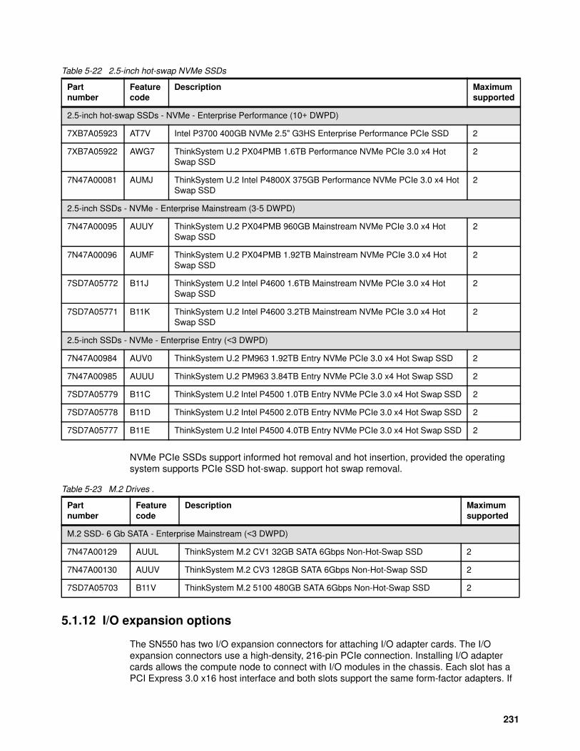
Table 5-22 2.5-inch hot-swap NVMe SSDs
NVMe PCIe SSDs support informed hot removal and hot insertion, provided the operating system supports PCIe SSD hot-swap. support hot swap removal.
Table 5-23 M.2 Drives .
5.1.12 I/O expansion options
The SN550 has two I/O expansion connectors for attaching I/O adapter cards. The I/O expansion connectors use a high-density, 216-pin PCIe connection. Installing I/O adapter cards allows the compute node to connect with I/O modules in the chassis. Each slot has a PCI Express 3.0 x16 host interface and both slots support the same form-factor adapters. If
Partnumber
Feature code
Description Maximumsupported
2.5-inch hot-swap SSDs - NVMe - Enterprise Performance (10+ DWPD)
7XB7A05923 AT7V Intel P3700 400GB NVMe 2.5" G3HS Enterprise Performance PCIe SSD 2
7XB7A05922 AWG7 ThinkSystem U.2 PX04PMB 1.6TB Performance NVMe PCIe 3.0 x4 Hot Swap SSD
2
7N47A00081 AUMJ ThinkSystem U.2 Intel P4800X 375GB Performance NVMe PCIe 3.0 x4 Hot Swap SSD
2
2.5-inch SSDs - NVMe - Enterprise Mainstream (3-5 DWPD)
7N47A00095 AUUY ThinkSystem U.2 PX04PMB 960GB Mainstream NVMe PCIe 3.0 x4 Hot Swap SSD
2
7N47A00096 AUMF ThinkSystem U.2 PX04PMB 1.92TB Mainstream NVMe PCIe 3.0 x4 Hot Swap SSD
2
7SD7A05772 B11J ThinkSystem U.2 Intel P4600 1.6TB Mainstream NVMe PCIe 3.0 x4 Hot Swap SSD
2
7SD7A05771 B11K ThinkSystem U.2 Intel P4600 3.2TB Mainstream NVMe PCIe 3.0 x4 Hot Swap SSD
2
2.5-inch SSDs - NVMe - Enterprise Entry (<3 DWPD)
7N47A00984 AUV0 ThinkSystem U.2 PM963 1.92TB Entry NVMe PCIe 3.0 x4 Hot Swap SSD 2
7N47A00985 AUUU ThinkSystem U.2 PM963 3.84TB Entry NVMe PCIe 3.0 x4 Hot Swap SSD 2
7SD7A05779 B11C ThinkSystem U.2 Intel P4500 1.0TB Entry NVMe PCIe 3.0 x4 Hot Swap SSD 2
7SD7A05778 B11D ThinkSystem U.2 Intel P4500 2.0TB Entry NVMe PCIe 3.0 x4 Hot Swap SSD 2
7SD7A05777 B11E ThinkSystem U.2 Intel P4500 4.0TB Entry NVMe PCIe 3.0 x4 Hot Swap SSD 2
Partnumber
Feature code
Description Maximumsupported
M.2 SSD- 6 Gb SATA - Enterprise Mainstream (<3 DWPD)
7N47A00129 AUUL ThinkSystem M.2 CV1 32GB SATA 6Gbps Non-Hot-Swap SSD 2
7N47A00130 AUUV ThinkSystem M.2 CV3 128GB SATA 6Gbps Non-Hot-Swap SSD 2
7SD7A05703 B11V ThinkSystem M.2 5100 480GB SATA 6Gbps Non-Hot-Swap SSD 2
231
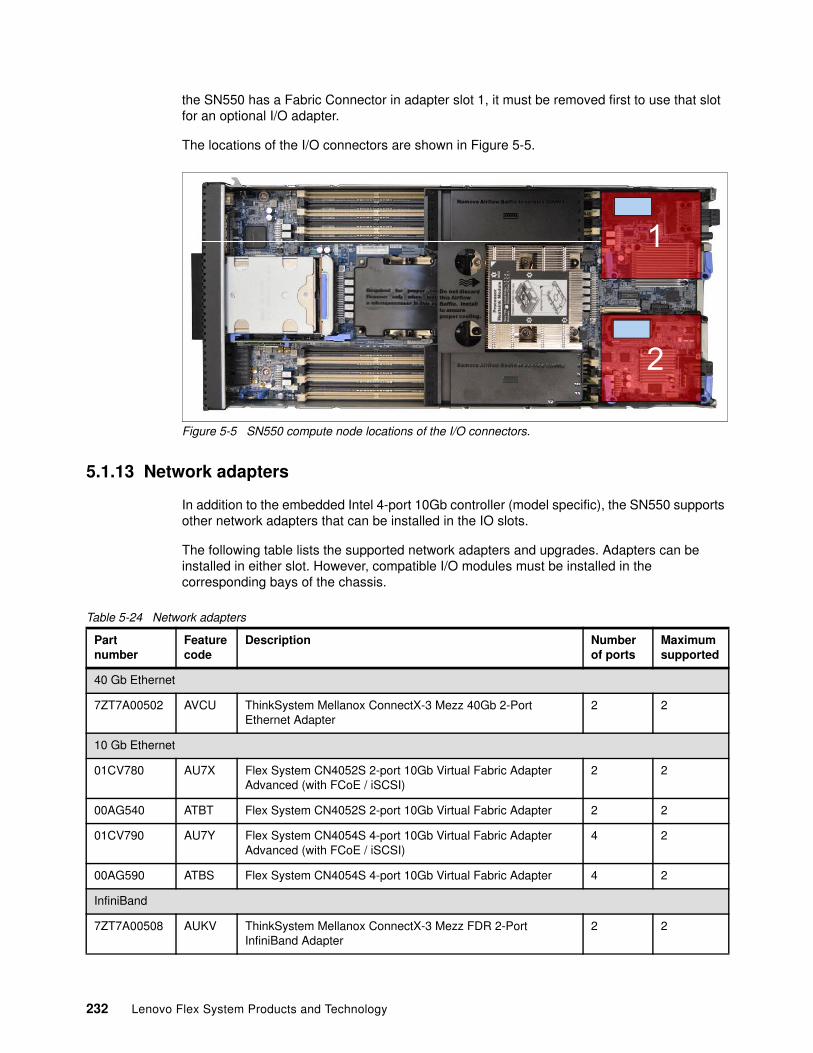
the SN550 has a Fabric Connector in adapter slot 1, it must be removed first to use that slot for an optional I/O adapter.
The locations of the I/O connectors are shown in Figure 5-5.
Figure 5-5 SN550 compute node locations of the I/O connectors.
5.1.13 Network adapters
In addition to the embedded Intel 4-port 10Gb controller (model specific), the SN550 supports other network adapters that can be installed in the IO slots.
The following table lists the supported network adapters and upgrades. Adapters can be installed in either slot. However, compatible I/O modules must be installed in the corresponding bays of the chassis.
Table 5-24 Network adapters
1
2
Partnumber
Featurecode
Description Numberof ports
Maximumsupported
40 Gb Ethernet
7ZT7A00502 AVCU ThinkSystem Mellanox ConnectX-3 Mezz 40Gb 2-Port Ethernet Adapter
2 2
10 Gb Ethernet
01CV780 AU7X Flex System CN4052S 2-port 10Gb Virtual Fabric Adapter Advanced (with FCoE / iSCSI)
2 2
00AG540 ATBT Flex System CN4052S 2-port 10Gb Virtual Fabric Adapter 2 2
01CV790 AU7Y Flex System CN4054S 4-port 10Gb Virtual Fabric Adapter Advanced (with FCoE / iSCSI)
4 2
00AG590 ATBS Flex System CN4054S 4-port 10Gb Virtual Fabric Adapter 4 2
InfiniBand
7ZT7A00508 AUKV ThinkSystem Mellanox ConnectX-3 Mezz FDR 2-Port InfiniBand Adapter
2 2
232 Lenovo Flex System Products and Technology
For details about these adapters, see 4.3, “I/O adapters” on page 173.
For more information about adapter-to-switch compatibility, see the Flex System Interoperability Guide:
http://lenovopress.com/fsig
5.1.14 Storage host bus adapters
The following table lists storage HBAs that are supported by the SN550. Storage HBAs are supported in both slots, however for CTO orders, an HBA is installed only in slot 2.
Table 5-25 Storage adapters
For details about these adapters, see 4.3, “I/O adapters” on page 173.
5.1.15 Integrated virtualization
The integrated SATA controller can be used with virtualization hypervisors, including VMware ESXi, Linux KVM, Xen, and Microsoft Hyper-V. However, support is limited to AHCI (non-RAID) mode. RSTe mode is not supported with virtualization hypervisors.
The compute node also supports booting from a hypervisor installed on an M.2 solid-state drive.
There are two types of M.2 adapters supported in the SN550:
� Single M.2 Adapter, which supports one M.2 drive; available as the ThinkSystem M.2 Enablement Kit
� Dual M.2 Adapter, which supports one or two M.2 drives; available as the ThinkSystem M.2 with Mirroring Enablement Kit
The enablement kit is first selected - either single, or dual. Dual would be selected where mirroring is required. The required SSD media can then be selected and is installed onto the enablement kit.
Table 5-26 lists both the enablement kits and the SSD media that is available for the SN550.
FCoE and iSCSI support: ThinkSystem compute node adapters do not support Features on Demand, so the CN4052S and CN4054S 2-port 10Gb basic adapters cannot be upgraded to FCoE support. If you need FCoE or iSCSI support use the 01CV780 or 01CV790 adapters
Partnumber
Featurecode
Description Numberof ports
Maximumsupported
Fibre Channel
7ZT7A00520 AVCV ThinkSystem QLogic QML2692 Mezz 16Gb 2-Port Fibre Channel Adapter
2 2
7ZT7A00521 AVCW ThinkSystem Emulex LPm16002B-L Mezz 16Gb 2-Port Fibre Channel Adapter
2 2
7ZT7A00522 AVCX ThinkSystem Emulex LPm16004B-L Mezz 16Gb 4-Port Fibre Channel Adapter
4 2
233
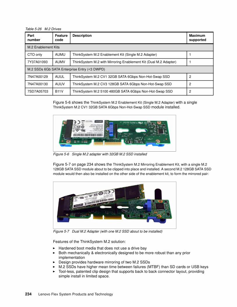
Table 5-26 M.2 Drives
Figure 5-6 shows the ThinkSystem M.2 Enablement Kit (Single M.2 Adapter) with a single ThinkSystem M.2 CV1 32GB SATA 6Gbps Non-Hot-Swap SSD module installed.
Figure 5-6 Single M.2 adapter with 32GB M.2 SSD installed
Figure 5-7 on page 234 shows the ThinkSystem M.2 Mirroring Enablement Kit, with a single M.2 128GB SATA SSD module about to be clipped into place and installed. A second M.2 128GB SATA SSD module would then also be installed on the other side of the enablement kit, to form the mirrored pair:
Figure 5-7 Dual M.2 Adapter (with one M.2 SSD about to be installed)
Features of the ThinkSystem M.2 solution:
� Hardened boot media that does not use a drive bay� Both mechanically & electronically designed to be more robust than any prior
implementation� Design provides hardware mirroring of two M.2 SSDs� M.2 SSDs have higher mean time between failures (MTBF) than SD cards or USB keys� Tool-less, patented clip design that supports back to back connector layout, providing
simple install in limited space.
Partnumber
Featurecode
Description Maximumsupported
M.2 Enablement Kits
CTO only AUMU ThinkSystem M.2 Enablement Kit (Single M.2 Adapter) 1
7Y37A01093 AUMV ThinkSystem M.2 with Mirroring Enablement Kit (Dual M.2 Adapter) 1
M.2 SSDs 6Gb SATA Enterprise Entry (<3 DWPD)
7N47A00129 AUUL ThinkSystem M.2 CV1 32GB SATA 6Gbps Non-Hot-Swap SSD 2
7N47A00130 AUUV ThinkSystem M.2 CV3 128GB SATA 6Gbps Non-Hot-Swap SSD 2
7SD7A05703 B11V ThinkSystem M.2 5100 480GB SATA 6Gbps Non-Hot-Swap SSD 2
234 Lenovo Flex System Products and Technology
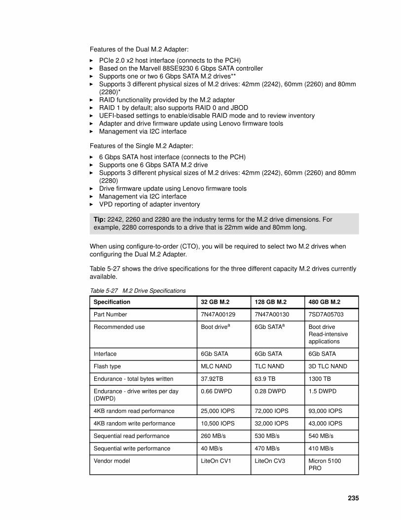
Features of the Dual M.2 Adapter:
� PCIe 2.0 x2 host interface (connects to the PCH)� Based on the Marvell 88SE9230 6 Gbps SATA controller� Supports one or two 6 Gbps SATA M.2 drives**� Supports 3 different physical sizes of M.2 drives: 42mm (2242), 60mm (2260) and 80mm
(2280)*� RAID functionality provided by the M.2 adapter� RAID 1 by default; also supports RAID 0 and JBOD� UEFI-based settings to enable/disable RAID mode and to review inventory� Adapter and drive firmware update using Lenovo firmware tools� Management via I2C interface
Features of the Single M.2 Adapter:
� 6 Gbps SATA host interface (connects to the PCH)� Supports one 6 Gbps SATA M.2 drive� Supports 3 different physical sizes of M.2 drives: 42mm (2242), 60mm (2260) and 80mm
(2280)� Drive firmware update using Lenovo firmware tools� Management via I2C interface� VPD reporting of adapter inventory
When using configure-to-order (CTO), you will be required to select two M.2 drives when configuring the Dual M.2 Adapter.
Table 5-27 shows the drive specifications for the three different capacity M.2 drives currently available.
Table 5-27 M.2 Drive Specifications
Tip: 2242, 2260 and 2280 are the industry terms for the M.2 drive dimensions. For example, 2280 corresponds to a drive that is 22mm wide and 80mm long.
Specification 32 GB M.2 128 GB M.2 480 GB M.2
Part Number 7N47A00129 7N47A00130 7SD7A05703
Recommended use Boot drivea 6Gb SATAa Boot driveRead-intensive applications
Interface 6Gb SATA 6Gb SATA 6Gb SATA
Flash type MLC NAND TLC NAND 3D TLC NAND
Endurance - total bytes written 37.92TB 63.9 TB 1300 TB
Endurance - drive writes per day (DWPD)
0.66 DWPD 0.28 DWPD 1.5 DWPD
4KB random read performance 25,000 IOPS 72,000 IOPS 93,000 IOPS
4KB random write performance 10,500 IOPS 32,000 IOPS 43,000 IOPS
Sequential read performance 260 MB/s 530 MB/s 540 MB/s
Sequential write performance 40 MB/s 470 MB/s 410 MB/s
Vendor model LiteOn CV1 LiteOn CV3 Micron 5100 PRO
235
VMware ESXi is available as a factory installed option for the M.2 drives. Feature codes are shown in Table 5-28, there are no part numbers as these are only available as factory installed via CTO:
Table 5-28 VMware factory installed features
Alternatively, you can download supported VMware vSphere hypervisor images from the following web page and load it on the M.2 drives using the instructions provided:
http://www3.lenovo.com/us/en/data-center/solutions/alliances/vmware/#tab-VMware-tab-main-2
5.1.16 Light path diagnostics
The SN550 includes light path diagnostics. If an environmental condition exceeds a threshold or if a system component fails, XCC lights LEDs inside the compute node to help you diagnose the problem and find the failing part.
For quick problem determination when you are physically at the compute node, the compute node offers the following three-step guided path:
� Illuminate the fault LED on the front panel. � Identify the fault in the light path diagnostics panel, as shown in the following figure.� If a DIMM is faulty, the LED next to it is illuminated.
The SN550 light path diagnostics panel is inside the compute node near the front panel, as shown in the following figure.
Dimensions 42 x 22 mm 80 x 22 mm 80 x 22 mm
a. These drive options do not have power-loss capacitors, which means they do not have protection against a potential loss of data when a write operation is underway just as a power outage occurs. As a result, these drives are not recommended for general purpose storage functions
Part Number Feature Code Description
CTO only AXFT VMware ESXi 6.5 (factory installed)
CTO only AXFS VMware ESXi 6.0 U3 (factory installed)
Specification 32 GB M.2 128 GB M.2 480 GB M.2
236 Lenovo Flex System Products and Technology
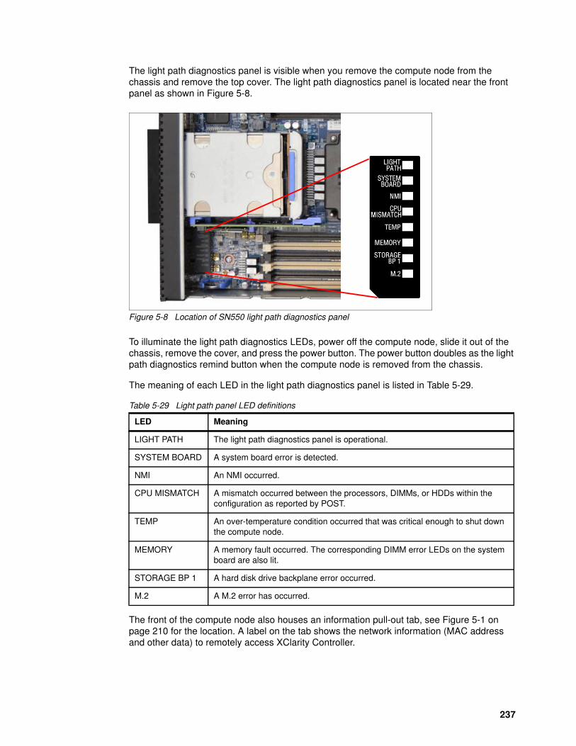
The light path diagnostics panel is visible when you remove the compute node from the chassis and remove the top cover. The light path diagnostics panel is located near the front panel as shown in Figure 5-8.
Figure 5-8 Location of SN550 light path diagnostics panel
To illuminate the light path diagnostics LEDs, power off the compute node, slide it out of the chassis, remove the cover, and press the power button. The power button doubles as the light path diagnostics remind button when the compute node is removed from the chassis.
The meaning of each LED in the light path diagnostics panel is listed in Table 5-29.
Table 5-29 Light path panel LED definitions
The front of the compute node also houses an information pull-out tab, see Figure 5-1 on page 210 for the location. A label on the tab shows the network information (MAC address and other data) to remotely access XClarity Controller.
LED Meaning
LIGHT PATH The light path diagnostics panel is operational.
SYSTEM BOARD A system board error is detected.
NMI An NMI occurred.
CPU MISMATCH A mismatch occurred between the processors, DIMMs, or HDDs within the configuration as reported by POST.
TEMP An over-temperature condition occurred that was critical enough to shut down the compute node.
MEMORY A memory fault occurred. The corresponding DIMM error LEDs on the system board are also lit.
STORAGE BP 1 A hard disk drive backplane error occurred.
M.2 A M.2 error has occurred.
237
5.1.17 Operating system support
The SN550 compute node supports the following operating systems:
� Microsoft Windows Server 2012 R2� Microsoft Windows Server 2016� Microsoft Windows Server, version 1709� Red Hat Enterprise Linux 6.9 x64� Red Hat Enterprise Linux 7.3� Red Hat Enterprise Linux 7.4� SUSE Linux Enterprise Server 11 Xen x64 SP4� SUSE Linux Enterprise Server 11 x64 SP4� SUSE Linux Enterprise Server 12 SP2� SUSE Linux Enterprise Server 12 SP3� SUSE Linux Enterprise Server 12 Xen SP2� SUSE Linux Enterprise Server 12 Xen SP3� VMware ESXi 6.0 U3� VMware ESXi 6.5� VMware ESXi 6.5 U1
For more information about the specific versions and service levels that are supported, see the Operating System Interoperability Guide:
https://lenovopress.com/osig#servers=sn550-7x16
5.1.18 Physical specifications
The compute node features the following dimensions and weight (approximate):
� Height: 51 mm (2.0 in)� Depth: 493 mm (19.4 in)� Width: 215 mm (8.5 in)� Maximum weight: 7.1 kg (15.6 lb)
5.1.19 Supported environment
The SN550 compute node complies with ASHRAE Class A3 specifications.
The Lenovo ThinkSystem SN550 compute node complies with ASHRAE Class A3 specifications. System performance may be impacted when operating temperature is above ASHRAE A3 specification or fan failed condition.
� Air temperature:
– Operating:• ASHRAE Class A2: 10 °C - 35 °C (50 °F - 95 °F); decrease the maximum ambient
temperature by 1 °C for every 300 m (984 ft) increase in altitude above 900 m (2,953 ft)
• ASHRAE Class A3: 5 °C - 40 °C (41 °F - 104 °F); decrease the maximum ambient temperature by 1 °C for every 175 m (574 ft) increase in altitude above 900 m (2,953 ft)
– Compute node off: 5°C to 45°C (41°F to 113°F)– Shipment/Storage: -40 °C to 60 °C (-40 °F to 140 °F)
� Maximum altitude: 3,050 m (10,000 ft)
� Relative Humidity (non-condensing):
– Operating:
238 Lenovo Flex System Products and Technology

• ASHRAE Class A2: 8% - 80%, maximum dew point: 21°C (70°F)• ASHRAE Class A3: 8% - 85%, maximum dew point: 24°C (75°F)
– Shipment/Storage: 8% - 90%
239
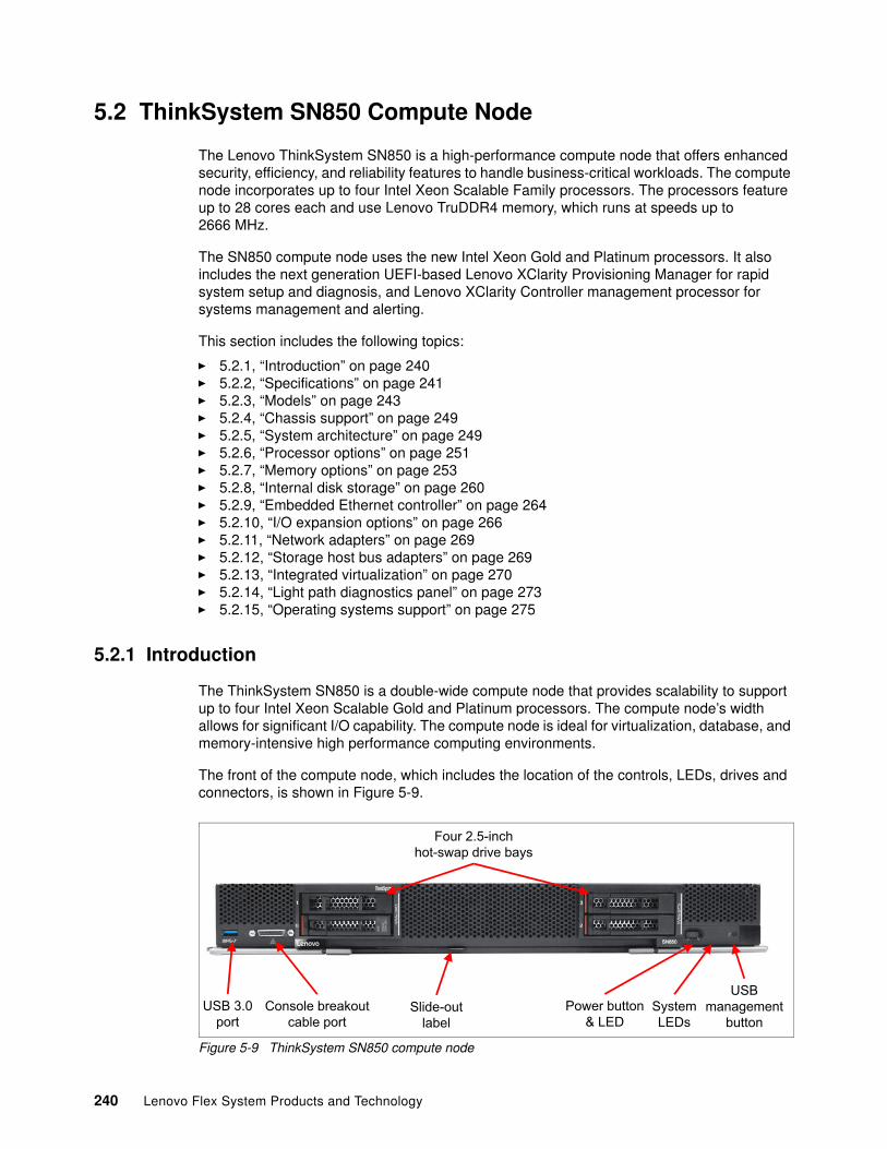
5.2 ThinkSystem SN850 Compute Node
The Lenovo ThinkSystem SN850 is a high-performance compute node that offers enhanced security, efficiency, and reliability features to handle business-critical workloads. The compute node incorporates up to four Intel Xeon Scalable Family processors. The processors feature up to 28 cores each and use Lenovo TruDDR4 memory, which runs at speeds up to 2666 MHz.
The SN850 compute node uses the new Intel Xeon Gold and Platinum processors. It also includes the next generation UEFI-based Lenovo XClarity Provisioning Manager for rapid system setup and diagnosis, and Lenovo XClarity Controller management processor for systems management and alerting.
This section includes the following topics:
� 5.2.1, “Introduction” on page 240� 5.2.2, “Specifications” on page 241� 5.2.3, “Models” on page 243� 5.2.4, “Chassis support” on page 249� 5.2.5, “System architecture” on page 249� 5.2.6, “Processor options” on page 251� 5.2.7, “Memory options” on page 253� 5.2.8, “Internal disk storage” on page 260� 5.2.9, “Embedded Ethernet controller” on page 264� 5.2.10, “I/O expansion options” on page 266� 5.2.11, “Network adapters” on page 269� 5.2.12, “Storage host bus adapters” on page 269� 5.2.13, “Integrated virtualization” on page 270� 5.2.14, “Light path diagnostics panel” on page 273� 5.2.15, “Operating systems support” on page 275
5.2.1 Introduction
The ThinkSystem SN850 is a double-wide compute node that provides scalability to support up to four Intel Xeon Scalable Gold and Platinum processors. The compute node’s width allows for significant I/O capability. The compute node is ideal for virtualization, database, and memory-intensive high performance computing environments.
The front of the compute node, which includes the location of the controls, LEDs, drives and connectors, is shown in Figure 5-9.
Figure 5-9 ThinkSystem SN850 compute node
USB 3.0port
Console breakoutcable port
USBmanagement
buttonPower button
& LEDSystemLEDs
Slide-outlabel
Four 2.5-inch hot-swap drive bays
240 Lenovo Flex System Products and Technology
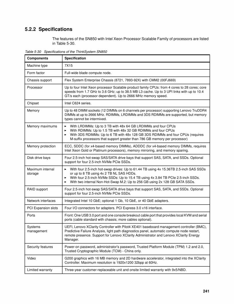
5.2.2 Specifications
The features of the SN850 with Intel Xeon Processor Scalable Family of processors are listed in Table 5-30.
Table 5-30 Specifications of the ThinkSystem SN850
Components Specification
Machine type 7X15
Form factor Full-wide blade compute node.
Chassis support Flex System Enterprise Chassis (8721, 7893-92X) with CMM2 (00FJ669)
Processor Up to four Intel Xeon processor Scalable product family CPUs: from 4 cores to 28 cores; core speeds from 1.7 GHz to 3.6 GHz; up to 38.5 MB L3 cache. Up to 3 UPI links with up to 10.4 GT/s each (processor dependent). Up to 2666 MHz memory speed.
Chipset Intel C624 series.
Memory Up to 48 DIMM sockets (12 DIMMs on 6 channels per processor) supporting Lenovo TruDDR4 DIMMs at up to 2666 MHz. RDIMMs, LRDIMMs and 3DS RDIMMs are supported, but memory types cannot be intermixed.
Memory maximums � With LRDIMMs: Up to 3 TB with 48x 64 GB LRDIMMs and four CPUs� With RDIMMs: Up to 1.5 TB with 48x 32 GB RDIMMs and four CPUs� With 3DS RDIMMs: Up to 6 TB with 48x 128 GB 3DS RDIMMs and four CPUs (requires
M-suffix processors that support greater than 786 GB memory per processor)
Memory protection ECC, SDDC (for x4-based memory DIMMs), ADDDC (for x4-based memory DIMMs, requires Intel Xeon Gold or Platinum processors), memory mirroring, and memory sparing.
Disk drive bays Four 2.5-inch hot-swap SAS/SATA drive bays that support SAS, SATA, and SSDs. Optional support for four 2.5-inch NVMe PCIe SSDs.
Maximum internal storage
� With four 2.5-inch hot-swap drives: Up to 61.44 TB using 4x 15.36TB 2.5-inch SAS SSDs or up to 8 TB using 4x 2 TB NL SAS HDDs.
� With four 2.5-inch NVMe SSDs: Up to 15.4 TB using 4x 3.84 TB PCIe 2.5-inch SSDs.� With two internal Non-Hot-Swap M.2: Up to 256 GB using 2x 128 GB SATA SSDs.
RAID support Four 2.5-inch hot-swap SAS/SATA drive bays that support SAS, SATA, and SSDs. Optional support for four 2.5-inch NVMe PCIe SSDs.
Network interfaces Integrated Intel 10 GbE; optional 1 Gb, 10 GbE, or 40 GbE adapters.
PCI Expansion slots Four I/O connectors for adapters. PCI Express 3.0 x16 interface.
Ports Front: One USB 3.0 port and one console breakout cable port that provides local KVM and serial ports (cable standard with chassis; more cables optional).
Systems management
UEFI, Lenovo XClarity Controller with Pilot4 XE401 baseboard management controller (BMC), Predictive Failure Analysis, light path diagnostics panel, automatic compute node restart, remote presence. Support for Lenovo XClarity Administrator and Lenovo XClarity Energy Manager.
Security features Power-on password, administrator's password, Trusted Platform Module (TPM) 1.2 and 2.0, Trusted Cryptographic Module (TCM) - China only.
Video G200 graphics with 16 MB memory and 2D hardware accelerator, integrated into the XClarity Controller. Maximum resolution is 1920x1200 32bpp at 60Hz.
Limited warranty Three-year customer-replaceable unit and onsite limited warranty with 9x5/NBD.
241
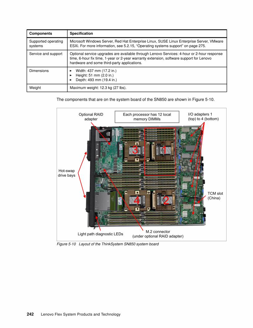
The components that are on the system board of the SN850 are shown in Figure 5-10.
Figure 5-10 Layout of the ThinkSystem SN850 system board
Supported operating systems
Microsoft Windows Server, Red Hat Enterprise Linux, SUSE Linux Enterprise Server, VMware ESXi. For more information, see 5.2.15, “Operating systems support” on page 275.
Service and support Optional service upgrades are available through Lenovo Services: 4-hour or 2-hour response time, 6-hour fix time, 1-year or 2-year warranty extension, software support for Lenovo hardware and some third-party applications.
Dimensions � Width: 437 mm (17.2 in.)� Height: 51 mm (2.0 in.)� Depth: 493 mm (19.4 in.)
Weight Maximum weight: 12.3 kg (27 lbs).
Components Specification
I/O adapters 1 (top) to 4 (bottom)
Each processor has 12 local memory DIMMs
Light path diagnostic LEDs
1
2
3
4
Optional RAID adapter
Hot-swapdrive bays
M.2 connector(under optional RAID adapter)
TCM slot(China)
242 Lenovo Flex System Products and Technology
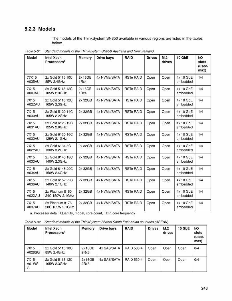
5.2.3 Models
The models of the ThinkSystem SN850 available in various regions are listed in the tables below.
Table 5-31 Standard models of the ThinkSystem SN850 Australia and New Zealand
Table 5-32 Standard models of the ThinkSystem SN850 South East Asian countries (ASEAN)
Model Intel Xeon Processorsa
a. Processor detail: Quantity, model, core count, TDP, core frequency
Memory Drive bays RAID Drives M.2drives
10 GbE I/O slots(used/max)
77X15 A035AU
2x Gold 5115 10C 85W 2.4GHz
2x 16GB 1Rx4
4x NVMe/SATA RSTe RAID Open Open 4x 10 GbEembedded
1/4
7X15 A00JAU
2x Gold 5118 12C 105W 2.3GHz
2x 16GB 1Rx4
4x NVMe/SATA RSTe RAID Open Open 4x 10 GbEembedded
1/4
7X15 A02ZAU
2x Gold 5118 12C 105W 2.3GHz
2x 32GB 4x NVMe/SATA RSTe RAID Open Open 4x 10 GbEembedded
1/4
7X15 A030AU
2x Gold 5120 14C 105W 2.2GHz
2x 32GB 4x NVMe/SATA RSTe RAID Open Open 4x 10 GbEembedded
1/4
7X15 A031AU
2x Gold 6126 12C 125W 2.6GHz
2x 32GB 4x NVMe/SATA RSTe RAID Open Open 4x 10 GbEembedded
1/4
7X15 A032AU
2x Gold 6130 16C 125W 2.1GHz
2x 32GB 4x NVMe/SATA RSTe RAID Open Open 4x 10 GbEembedded
1/4
7X15 A02YAU
2x Gold 6134 8C 130W 3.2GHz
2x 32GB 4x NVMe/SATA RSTe RAID Open Open 4x 10 GbEembedded
1/4
7X15 A033AU
2x Gold 6140 18C 140W 2.3GHz
2x 32GB 4x NVMe/SATA RSTe RAID Open Open 4x 10 GbEembedded
1/4
7X15 A034AU
2x Gold 6148 20C 150W 2.4GHz
2x 32GB 4x NVMe/SATA RSTe RAID Open Open 4x 10 GbEembedded
1/4
7X15 A036AU
2x Gold 6152 22C 140W 2.1GHz
2x 32GB 4x NVMe/SATA RSTe RAID Open Open 4x 10 GbEembedded
1/4
7X15 A02XAU
2x Platinum 816024C 150W 2.1GHz
2x 32GB 4x NVMe/SATA RSTe RAID Open Open 4x 10 GbEembedded
1/4
7X15 A037AU
2x Platinum 817628C 165W 2.1GHz
2x 32GB 4x NVMe/SATA RSTe RAID Open Open 4x 10 GbEembedded
1/4
Model Intel Xeon Processorsa
Memory Drive bays RAID Drives M.2drives
10 GbE I/O slots(used/max)
7X15 A028SG
2x Gold 5115 10C 85W 2.4GHz
2x 16GB 2Rx8
4x SAS/SATA RAID 530-4i Open Open Open 0/4
7X15 A01WSG
2x Gold 5118 12C 105W 2.3GHz
2x 16GB 2Rx8
4x SAS/SATA RAID 530-4i Open Open Open 0/4
243
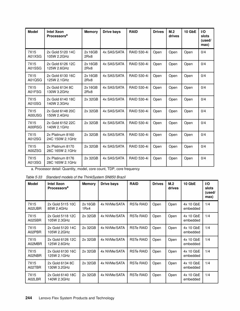
Table 5-33 Standard models of the ThinkSystem SN850 Brazil
7X15 A01XSG
2x Gold 5120 14C 105W 2.2GHz
2x 16GB 2Rx8
4x SAS/SATA RAID 530-4i Open Open Open 0/4
7X15 A01SSG
2x Gold 6126 12C 125W 2.6GHz
2x 16GB 2Rx8
4x SAS/SATA RAID 530-4i Open Open Open 0/4
7X15 A01QSG
2x Gold 6130 16C 125W 2.1GHz
2x 16GB 2Rx8
4x SAS/SATA RAID 530-4i Open Open Open 0/4
7X15 A01FSG
2x Gold 6134 8C 130W 3.2GHz
2x 16GB 2Rx8
4x SAS/SATA RAID 530-4i Open Open Open 0/4
7X15 A010SG
2x Gold 6140 18C 140W 2.3GHz
2x 32GB 4x SAS/SATA RAID 530-4i Open Open Open 0/4
7X15 A00USG
2x Gold 6148 20C 150W 2.4GHz
2x 32GB 4x SAS/SATA RAID 530-4i Open Open Open 0/4
7X15 A00RSG
2x Gold 6152 22C 140W 2.1GHz
2x 32GB 4x SAS/SATA RAID 530-4i Open Open Open 0/4
7X15 A012SG
2x Platinum 8160 24C 150W 2.1GHz
2x 32GB 4x SAS/SATA RAID 530-4i Open Open Open 0/4
7X15 A00ZSG
2x Platinum 8170 26C 165W 2.1GHz
2x 32GB 4x SAS/SATA RAID 530-4i Open Open Open 0/4
7X15 A013SG
2x Platinum 817628C 165W 2.1GHz
2x 32GB 4x SAS/SATA RAID 530-4i Open Open Open 0/4
a. Processor detail: Quantity, model, core count, TDP, core frequency
Model Intel Xeon Processorsa
Memory Drive bays RAID Drives M.2drives
10 GbE I/O slots(used/max)
7X15 A02UBR
2x Gold 5115 10C 85W 2.4GHz
2x 16GB 1Rx4
4x NVMe/SATA RSTe RAID Open Open 4x 10 GbEembedded
1/4
7X15 A02SBR
2x Gold 5118 12C 105W 2.3GHz
2x 32GB 4x NVMe/SATA RSTe RAID Open Open 4x 10 GbEembedded
1/4
7X15 A02PBR
2x Gold 5120 14C 105W 2.2GHz
2x 32GB 4x NVMe/SATA RSTe RAID Open Open 4x 10 GbEembedded
1/4
7X15 A02MBR
2x Gold 6126 12C 125W 2.6GHz
2x 32GB 4x NVMe/SATA RSTe RAID Open Open 4x 10 GbEembedded
1/4
7X15 A02NBR
2x Gold 6130 16C 125W 2.1GHz
2x 32GB 4x NVMe/SATA RSTe RAID Open Open 4x 10 GbEembedded
1/4
7X15 A02TBR
2x Gold 6134 8C 130W 3.2GHz
2x 32GB 4x NVMe/SATA RSTe RAID Open Open 4x 10 GbEembedded
1/4
7X15 A02LBR
2x Gold 6140 18C 140W 2.3GHz
2x 32GB 4x NVMe/SATA RSTe RAID Open Open 4x 10 GbEembedded
1/4
Model Intel Xeon Processorsa
Memory Drive bays RAID Drives M.2drives
10 GbE I/O slots(used/max)
244 Lenovo Flex System Products and Technology
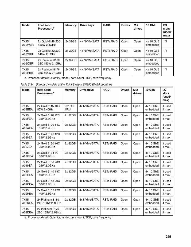
Table 5-34 Standard models of the ThinkSystem SN850 EMEA countries
7X15 A02WBR
2x Gold 6148 20C 150W 2.4GHz
2x 32GB 4x NVMe/SATA RSTe RAID Open Open 4x 10 GbEembedded
1/4
7X15 A02VBR
2x Gold 6152 22C 140W 2.1GHz
2x 32GB 4x NVMe/SATA RSTe RAID Open Open 4x 10 GbEembedded
1/4
7X15 A02QBR
2x Platinum 8160 24C 150W 2.1GHz
2x 32GB 4x NVMe/SATA RSTe RAID Open Open 4x 10 GbEembedded
1/4
7X15 A02RBR
2x Platinum 817628C 165W 2.1GHz
2x 32GB 4x NVMe/SATA RSTe RAID Open Open 4x 10 GbEembedded
1/4
a. Processor detail: Quantity, model, core count, TDP, core frequency
Model Intel Xeon Processorsa
a. Processor detail: Quantity, model, core count, TDP, core frequency
Memory Drive bays RAID Drives M.2drives
10 GbE I/O slots(used/max)
7X15 A02BEA
2x Gold 5115 10C 85W 2.4GHz
2x 16GB 1Rx4
4x NVMe/SATA RSTe RAID Open Open 4x 10 GbEembedded
1 used4 max
7X15 A02FEA
2x Gold 5118 12C 105W 2.3GHz
2x 32GB 4x NVMe/SATA RSTe RAID Open Open 4x 10 GbEembedded
1 used4 max
7X15 A02AEA
2x Gold 5120 14C 105W 2.2GHz
2x 32GB 4x NVMe/SATA RSTe RAID Open Open 4x 10 GbEembedded
1 used4 max
7X15 A029EA
2x Gold 6126 12C 125W 2.6GHz
2x 32GB 4x NVMe/SATA RSTe RAID Open Open 4x 10 GbEembedded
1 used4 max
7X15 A02JEA
2x Gold 6130 16C 125W 2.1GHz
2x 32GB 4x NVMe/SATA RSTe RAID Open Open 4x 10 GbEembedded
1 used4 max
7X15 A02GEA
2x Gold 6134 8C 130W 3.2GHz
2x 32GB 4x NVMe/SATA RSTe RAID Open Open 4x 10 GbEembedded
1 used4 max
7X15 A019EA
2x Gold 6138 20C 125W 2.0GHz
2x 32GB 4x NVMe/SATA RSTe RAID Open Open 4x 10 GbEembedded
1 used4 max
7X15 A02EEA
2x Gold 6140 18C 140W 2.3GHz
2x 32GB 4x NVMe/SATA RSTe RAID Open Open 4x 10 GbEembedded
1 used4 max
7X15 A02CEA
2x Gold 6148 20C 150W 2.4GHz
2x 32GB 4x NVMe/SATA RSTe RAID Open Open 4x 10 GbEembedded
1 used4 max
7X15 A02HEA
2x Gold 6152 22C 140W 2.1GHz
2x 32GB 4x NVMe/SATA RSTe RAID Open Open 4x 10 GbEembedded
1 used4 max
7X15 A02KEA
2x Platinum 8160 24C 150W 2.1GHz
2x 32GB 4x NVMe/SATA RSTe RAID Open Open 4x 10 GbEembedded
1 used4 max
7X15 A02DEA
2x Platinum 817628C 165W 2.1GHz
2x 32GB 4x NVMe/SATA RSTe RAID Open Open 4x 10 GbEembedded
1 used4 max
Model Intel Xeon Processorsa
Memory Drive bays RAID Drives M.2drives
10 GbE I/O slots(used/max)
245
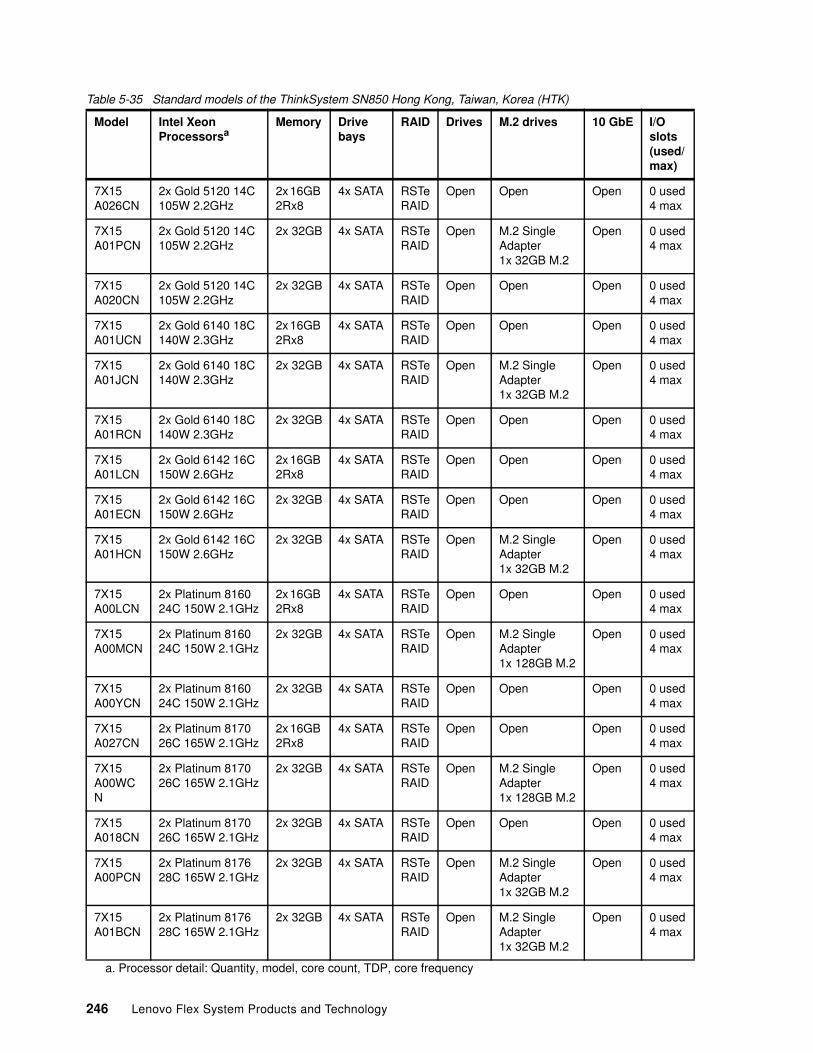
Table 5-35 Standard models of the ThinkSystem SN850 Hong Kong, Taiwan, Korea (HTK)
Model Intel Xeon Processorsa
a. Processor detail: Quantity, model, core count, TDP, core frequency
Memory Drive bays
RAID Drives M.2 drives 10 GbE I/O slots(used/max)
7X15 A026CN
2x Gold 5120 14C 105W 2.2GHz
2x 16GB 2Rx8
4x SATA RSTe RAID
Open Open Open 0 used4 max
7X15 A01PCN
2x Gold 5120 14C 105W 2.2GHz
2x 32GB 4x SATA RSTe RAID
Open M.2 Single Adapter1x 32GB M.2
Open 0 used4 max
7X15 A020CN
2x Gold 5120 14C 105W 2.2GHz
2x 32GB 4x SATA RSTe RAID
Open Open Open 0 used4 max
7X15 A01UCN
2x Gold 6140 18C 140W 2.3GHz
2x 16GB 2Rx8
4x SATA RSTe RAID
Open Open Open 0 used4 max
7X15 A01JCN
2x Gold 6140 18C 140W 2.3GHz
2x 32GB 4x SATA RSTe RAID
Open M.2 Single Adapter1x 32GB M.2
Open 0 used4 max
7X15 A01RCN
2x Gold 6140 18C 140W 2.3GHz
2x 32GB 4x SATA RSTe RAID
Open Open Open 0 used4 max
7X15 A01LCN
2x Gold 6142 16C 150W 2.6GHz
2x 16GB 2Rx8
4x SATA RSTe RAID
Open Open Open 0 used4 max
7X15 A01ECN
2x Gold 6142 16C 150W 2.6GHz
2x 32GB 4x SATA RSTe RAID
Open Open Open 0 used4 max
7X15 A01HCN
2x Gold 6142 16C 150W 2.6GHz
2x 32GB 4x SATA RSTe RAID
Open M.2 Single Adapter1x 32GB M.2
Open 0 used4 max
7X15 A00LCN
2x Platinum 8160 24C 150W 2.1GHz
2x 16GB 2Rx8
4x SATA RSTe RAID
Open Open Open 0 used4 max
7X15 A00MCN
2x Platinum 8160 24C 150W 2.1GHz
2x 32GB 4x SATA RSTe RAID
Open M.2 SingleAdapter1x 128GB M.2
Open 0 used4 max
7X15 A00YCN
2x Platinum 8160 24C 150W 2.1GHz
2x 32GB 4x SATA RSTe RAID
Open Open Open 0 used4 max
7X15 A027CN
2x Platinum 8170 26C 165W 2.1GHz
2x 16GB 2Rx8
4x SATA RSTe RAID
Open Open Open 0 used4 max
7X15 A00WCN
2x Platinum 8170 26C 165W 2.1GHz
2x 32GB 4x SATA RSTe RAID
Open M.2 Single Adapter1x 128GB M.2
Open 0 used4 max
7X15 A018CN
2x Platinum 8170 26C 165W 2.1GHz
2x 32GB 4x SATA RSTe RAID
Open Open Open 0 used4 max
7X15 A00PCN
2x Platinum 8176 28C 165W 2.1GHz
2x 32GB 4x SATA RSTe RAID
Open M.2 Single Adapter1x 32GB M.2
Open 0 used4 max
7X15 A01BCN
2x Platinum 817628C 165W 2.1GHz
2x 32GB 4x SATA RSTe RAID
Open M.2 Single Adapter1x 32GB M.2
Open 0 used4 max
246 Lenovo Flex System Products and Technology
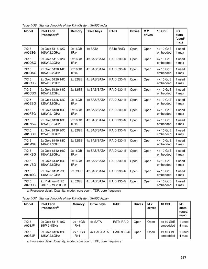
Table 5-36 Standard models of the ThinkSystem SN850 India
Table 5-37 Standard models of the ThinkSystem SN850 Japan
Model Intel Xeon Processorsa
a. Processor detail: Quantity, model, core count, TDP, core frequency
Memory Drive bays RAID Drives M.2drives
10 GbE I/O slots(used/max)
7X15 A009SG
2x Gold 5118 12C 105W 2.3GHz
2x 16GB 1Rx4
4x SATA RSTe RAID Open Open 4x 10 GbEembedded
1 used4 max
7X15 A00DSG
2x Gold 5118 12C 105W 2.3GHz
2x 16GB 1Rx4
4x SAS/SATA RAID 530-4i Open Open 4x 10 GbEembedded
1 used4 max
7X15 A00QSG
2x Gold 5120 14C 105W 2.2GHz
2x 16GB 1Rx4
4x SAS/SATA RAID 530-4i Open Open 4x 10 GbEembedded
1 used4 max
7X15 A006SG
2x Gold 5120 14C 105W 2.2GHz
2x 32GB 4x SAS/SATA RAID 530-4i Open Open 4x 10 GbEembedded
1 used4 max
7X15 A00CSG
2x Gold 5120 14C 105W 2.2GHz
2x 32GB 4x SAS/SATA RAID 930-4i Open Open 4x 10 GbEembedded
1 used4 max
7X15 A00ESG
2x Gold 6126 12C 125W 2.6GHz
2x 16GB 1Rx4
4x SAS/SATA RAID 530-4i Open Open 4x 10 GbEembedded
1 used4 max
7X15 A00FSG
2x Gold 6130 16C 125W 2.1GHz
2x 16GB 1Rx4
4x SAS/SATA RAID 530-4i Open Open 4x 10 GbEembedded
1 used4 max
7X15 A01NSG
2x Gold 6130 16C 125W 2.1GHz
2x 16GB 1Rx4
4x SAS/SATA RAID 930-4i Open Open 4x 10 GbEembedded
1 used4 max
7X15 A01DSG
2x Gold 6138 20C 125W 2.0GHz
2x 32GB 4x SAS/SATA RAID 930-4i Open Open 4x 10 GbEembedded
1 used4 max
7X15 A01MSG
2x Gold 6140 18C 140W 2.3GHz
2x 32GB 4x SAS/SATA RAID 930-4i Open Open 4x 10 GbEembedded
1 used4 max
7X15 A01KSG
2x Gold 6142 16C 150W 2.6GHz
2x 16GB 1Rx4
4x SAS/SATA RAID 930-4i Open Open 4x 10 GbEembedded
1 used4 max
7X15 A01VSG
2x Gold 6142 16C 150W 2.6GHz
2x 16GB 1Rx4
4x SAS/SATA RAID 530-4i Open Open 4x 10 GbEembedded
1 used4 max
7X15 A024SG
2x Gold 6152 22C 140W 2.1GHz
2x 32GB 4x SAS/SATA RAID 930-4i Open Open 4x 10 GbEembedded
1 used4 max
7X15 A025SG
2x Platinum 817628C 165W 2.1GHz
2x 32GB 4x SAS/SATA RAID 930-4i Open Open 4x 10 GbEembedded
1 used4 max
Model Intel Xeon Processorsa
a. Processor detail: Quantity, model, core count, TDP, core frequency
Memory Drive bays RAID Drives M.2drives
10 GbE I/O slots(used/max)
7X15 A008JP
2x Gold 5115 10C 85W 2.4GHz
2x 16GB 1Rx4
4x SATA RSTe RAID Open Open 4x 10 GbEembedded
1 used4 max
7X15 A00SJP
2x Gold 6126 12C 125W 2.6GHz
2x 16GB 1Rx4
4x SAS/SATA RAID 930-4i Open Open 4x 10 GbEembedded
1 used4 max
247
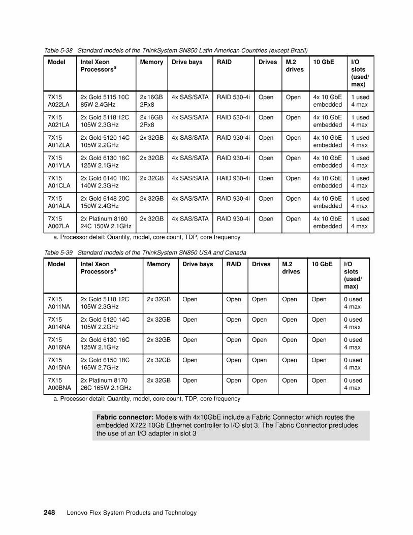
Table 5-38 Standard models of the ThinkSystem SN850 Latin American Countries (except Brazil)
Table 5-39 Standard models of the ThinkSystem SN850 USA and Canada
Model Intel Xeon Processorsa
a. Processor detail: Quantity, model, core count, TDP, core frequency
Memory Drive bays RAID Drives M.2 drives
10 GbE I/O slots(used/max)
7X15 A022LA
2x Gold 5115 10C 85W 2.4GHz
2x 16GB 2Rx8
4x SAS/SATA RAID 530-4i Open Open 4x 10 GbEembedded
1 used4 max
7X15 A021LA
2x Gold 5118 12C 105W 2.3GHz
2x 16GB 2Rx8
4x SAS/SATA RAID 530-4i Open Open 4x 10 GbEembedded
1 used4 max
7X15 A01ZLA
2x Gold 5120 14C 105W 2.2GHz
2x 32GB 4x SAS/SATA RAID 930-4i Open Open 4x 10 GbEembedded
1 used4 max
7X15 A01YLA
2x Gold 6130 16C 125W 2.1GHz
2x 32GB 4x SAS/SATA RAID 930-4i Open Open 4x 10 GbEembedded
1 used4 max
7X15 A01CLA
2x Gold 6140 18C 140W 2.3GHz
2x 32GB 4x SAS/SATA RAID 930-4i Open Open 4x 10 GbEembedded
1 used4 max
7X15 A01ALA
2x Gold 6148 20C 150W 2.4GHz
2x 32GB 4x SAS/SATA RAID 930-4i Open Open 4x 10 GbEembedded
1 used4 max
7X15 A007LA
2x Platinum 816024C 150W 2.1GHz
2x 32GB 4x SAS/SATA RAID 930-4i Open Open 4x 10 GbEembedded
1 used4 max
Model Intel Xeon Processorsa
a. Processor detail: Quantity, model, core count, TDP, core frequency
Memory Drive bays RAID Drives M.2drives
10 GbE I/O slots(used/max)
7X15 A011NA
2x Gold 5118 12C 105W 2.3GHz
2x 32GB Open Open Open Open Open 0 used4 max
7X15 A014NA
2x Gold 5120 14C 105W 2.2GHz
2x 32GB Open Open Open Open Open 0 used4 max
7X15 A016NA
2x Gold 6130 16C 125W 2.1GHz
2x 32GB Open Open Open Open Open 0 used4 max
7X15 A015NA
2x Gold 6150 18C 165W 2.7GHz
2x 32GB Open Open Open Open Open 0 used4 max
7X15 A00BNA
2x Platinum 817026C 165W 2.1GHz
2x 32GB Open Open Open Open Open 0 used4 max
Fabric connector: Models with 4x10GbE include a Fabric Connector which routes the embedded X722 10Gb Ethernet controller to I/O slot 3. The Fabric Connector precludes the use of an I/O adapter in slot 3
248 Lenovo Flex System Products and Technology
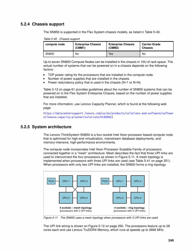
5.2.4 Chassis support
The SN850 is supported in the Flex System chassis models, as listed in Table 5-40.
Table 5-40 Chassis support
Up to seven SN850 Compute Nodes can be installed in the chassis in 10U of rack space. The actual number of systems that can be powered on in a chassis depends on the following factors:
� TDP power rating for the processors that are installed in the compute node.� Number of power supplies that are installed in the chassis.� Power redundancy policy that is used in the chassis (N+1 or N+N).
Table 3-12 on page 61 provides guidelines about the number of SN850 systems that can be powered on in the Flex System Enterprise Chassis, based on the number of power supplies that are installed.
For more information, use Lenovo Capacity Planner, which is found at the following web page:
https://datacentersupport.lenovo.com/us/en/products/solutions-and-software/software/lenovo-capacity-planner/solutions/ht504651
5.2.5 System architecture
The Lenovo ThinkSystem SN850 is a four-socket Intel Xeon processor-based compute node that is optimized for high-end virtualization, mainstream database deployments, and memory-intensive, high-performance environments.
The compute node incorporates Intel Xeon Processor Scalable Family of processors connected together in a “mesh” architecture. Mesh describes the fact that three UPI links are used to interconnect the four processors as shown in Figure 5-11. A mesh topology is implemented when processors with three UPI links are used (see Table 5-41 on page 251). When processors with only two UPI links are installed, the SN850 forms a ring topology.
Figure 5-11 The SN850 uses a mesh topology when processors with 3 UPI links are used
The UPI link wiring is shown on Figure 5-12 on page 250. The processors feature up to 28 cores each and use Lenovo TruDDR4 Memory, which runs at speeds up to 2666 MHz.
compute node Enterprise Chassis (CMM1)
Enterprise Chassis (CMM2)
Carrier-GradeChassis
SN850 No Yes No
CPU 4CPU 2
4 sockets – mesh topology(processors with 3 UPI links)
PCH CPU 3CPU 1
CPU 4CPU 2
4 sockets – ring topology(processors with 2 UPI links)
PCH CPU 3CPU 1
249

The ThinkSystem SN850 incorporates an integrated XClarity Controller, to provide a much improved user experience when managing the node via the web interface as well as local management via the USB port using the XClarity mobile application. This is described in 2.4.1, “XClarity Controller” on page 18.
Processors have the following features:
� Up to four interconnected Intel Xeon processor Scalable product family CPUs� 4 cores to 28 cores� Core speeds from 1.7 GHz to 3.6 GHz� up to 38.5 MB L3 cache� Up to 3 UPI links with up to 10.4 GT/s each (processor dependent)� Up to 2666 MHz memory speed.
The system has 48 DIMM sockets in total, these are organized with up to 12 DIMMs on 6 channels per processor. Each channel can accommodate up to two memory DIMMs, so with four processors the full 48 memory DIMMs are possible, giving a maximum of 6TB with 128 GB RDIMMs.
The system architecture of the SN850 compute node is shown in Figure 5-12.
Figure 5-12 System Architecture of the SN850 compute node
The SN850 compute node has the following standard architecture features:
� Four 3647-pin Socket P LGA sockets
� Four Enterprise Voltage Regulator Down (EVRD) regulators. The EVRD supplies both the processor core voltage and L2 cache voltage
3x UPI links
x4 DMI
I/O connector 1
I/O connector 2PCIe 3.0 x16
PCIe 3.0 x16
6 memory channels
PCIe 3.0 x8
PCIe 3.0 x8
IntelXeon
Processor 2
IntelXeon
Processor 12x USB 2.1
1x USB 3
PCIe 3.0 x1USB 2.1
VGA + Serial
4x 10Gb KR
Front KVM port
XCC
Front USB
4x 10GbE Fabric Connector
PCH
M.2 slotPCIe / SATA
4x 6
Gb
SAT
A
or
or4x NVMe/6Gb SATA
4x 12Gb SAS/SATARAID
adapter
4x 6Gb SATA
IntelXeon
Processor 3
IntelXeon
Processor 4 I/O connector 3
I/O connector 4PCIe 3.0 x16
PCIe 3.0 x16
250 Lenovo Flex System Products and Technology
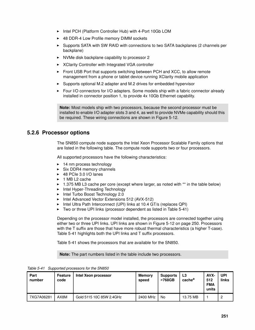
� Intel PCH (Platform Controller Hub) with 4-Port 10Gb LOM
� 48 DDR-4 Low Profile memory DIMM sockets
� Supports SATA with SW RAID with connections to two SATA backplanes (2 channels per backplane)
� NVMe disk backplane capability to processor 2
� XClarity Controller with Integrated VGA controller
� Front USB Port that supports switching between PCH and XCC, to allow remote management from a phone or tablet device running XClarity mobile application
� Supports optional M.2 adapter and M.2 drives for embedded hypervisor
� Four I/O connectors for I/O adapters. Some models ship with a fabric connector already installed in connector position 1, to provide 4x 10Gb Ethernet capability.
5.2.6 Processor options
The SN850 compute node supports the Intel Xeon Processor Scalable Family options that are listed in the following table. The compute node supports two or four processors.
All supported processors have the following characteristics:
� 14 nm process technology� Six DDR4 memory channels� 48 PCIe 3.0 I/O lanes� 1 MB L2 cache� 1.375 MB L3 cache per core (except where larger, as noted with ** in the table below)� Intel Hyper-Threading Technology� Intel Turbo Boost Technology 2.0 � Intel Advanced Vector Extensions 512 (AVX-512)� Intel Ultra Path Interconnect (UPI) links at 10.4 GT/s (replaces QPI)� Two or three UPI links (processor dependent as listed in Table 5-41)
Depending on the processor model installed, the processors are connected together using either two or three UPI links. UPI links are shown in Figure 5-12 on page 250. Processors with the T suffix are those that have more robust thermal characteristics (a higher T-case). Table 5-41 highlights both the UPI links and T suffix processors.
Table 5-41 shows the processors that are available for the SN850.
Table 5-41 Supported processors for the SN850
Note: Most models ship with two processors, because the second processor must be installed to enable I/O adapter slots 3 and 4, as well to provide NVMe capability should this be required. These wiring connections are shown in Figure 5-12.
Note: The part numbers listed in the table include two processors.
Partnumber
Featurecode
Intel Xeon processor Memoryspeed
Supports>768GB
L3cachea
AVX-512FMAunits
UPIlinks
7XG7A06281 AX8M Gold 5115 10C 85W 2.4GHz 2400 MHz No 13.75 MB 1 2
251
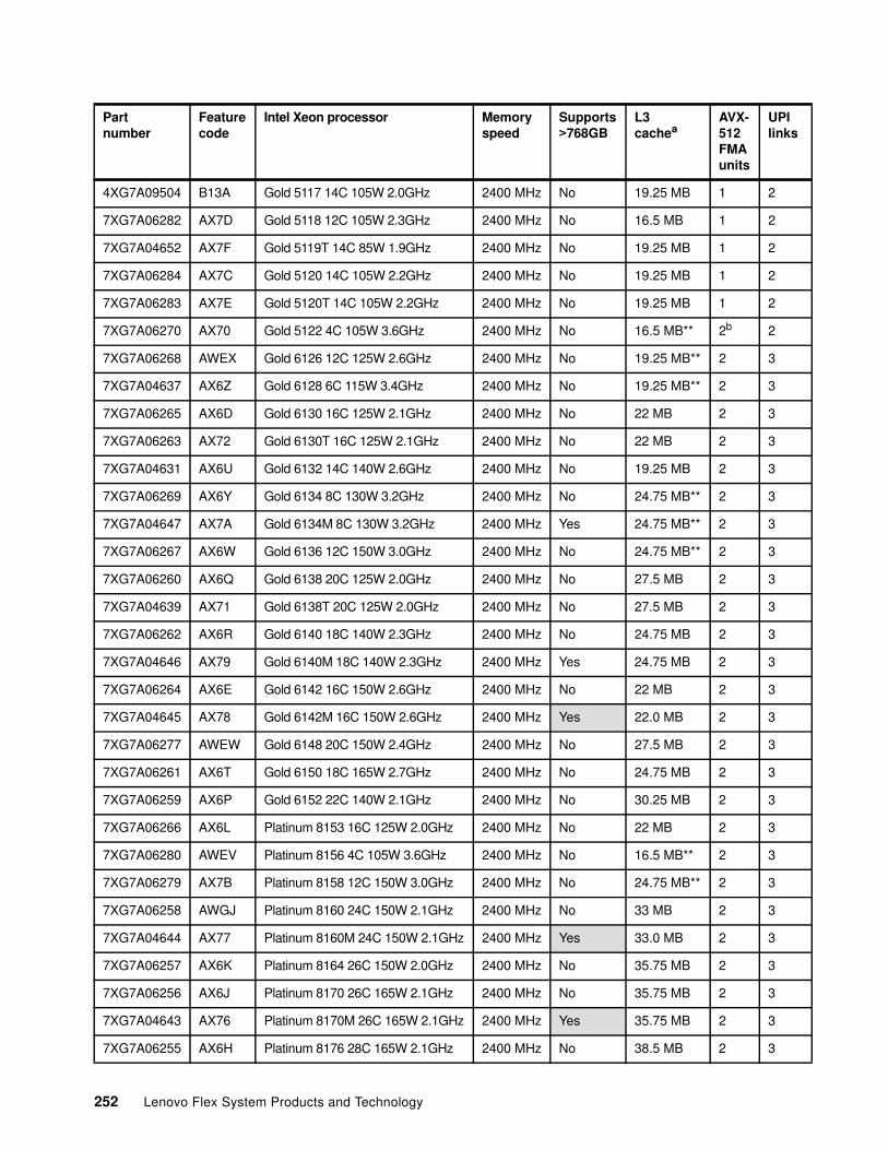
4XG7A09504 B13A Gold 5117 14C 105W 2.0GHz 2400 MHz No 19.25 MB 1 2
7XG7A06282 AX7D Gold 5118 12C 105W 2.3GHz 2400 MHz No 16.5 MB 1 2
7XG7A04652 AX7F Gold 5119T 14C 85W 1.9GHz 2400 MHz No 19.25 MB 1 2
7XG7A06284 AX7C Gold 5120 14C 105W 2.2GHz 2400 MHz No 19.25 MB 1 2
7XG7A06283 AX7E Gold 5120T 14C 105W 2.2GHz 2400 MHz No 19.25 MB 1 2
7XG7A06270 AX70 Gold 5122 4C 105W 3.6GHz 2400 MHz No 16.5 MB** 2b 2
7XG7A06268 AWEX Gold 6126 12C 125W 2.6GHz 2400 MHz No 19.25 MB** 2 3
7XG7A04637 AX6Z Gold 6128 6C 115W 3.4GHz 2400 MHz No 19.25 MB** 2 3
7XG7A06265 AX6D Gold 6130 16C 125W 2.1GHz 2400 MHz No 22 MB 2 3
7XG7A06263 AX72 Gold 6130T 16C 125W 2.1GHz 2400 MHz No 22 MB 2 3
7XG7A04631 AX6U Gold 6132 14C 140W 2.6GHz 2400 MHz No 19.25 MB 2 3
7XG7A06269 AX6Y Gold 6134 8C 130W 3.2GHz 2400 MHz No 24.75 MB** 2 3
7XG7A04647 AX7A Gold 6134M 8C 130W 3.2GHz 2400 MHz Yes 24.75 MB** 2 3
7XG7A06267 AX6W Gold 6136 12C 150W 3.0GHz 2400 MHz No 24.75 MB** 2 3
7XG7A06260 AX6Q Gold 6138 20C 125W 2.0GHz 2400 MHz No 27.5 MB 2 3
7XG7A04639 AX71 Gold 6138T 20C 125W 2.0GHz 2400 MHz No 27.5 MB 2 3
7XG7A06262 AX6R Gold 6140 18C 140W 2.3GHz 2400 MHz No 24.75 MB 2 3
7XG7A04646 AX79 Gold 6140M 18C 140W 2.3GHz 2400 MHz Yes 24.75 MB 2 3
7XG7A06264 AX6E Gold 6142 16C 150W 2.6GHz 2400 MHz No 22 MB 2 3
7XG7A04645 AX78 Gold 6142M 16C 150W 2.6GHz 2400 MHz Yes 22.0 MB 2 3
7XG7A06277 AWEW Gold 6148 20C 150W 2.4GHz 2400 MHz No 27.5 MB 2 3
7XG7A06261 AX6T Gold 6150 18C 165W 2.7GHz 2400 MHz No 24.75 MB 2 3
7XG7A06259 AX6P Gold 6152 22C 140W 2.1GHz 2400 MHz No 30.25 MB 2 3
7XG7A06266 AX6L Platinum 8153 16C 125W 2.0GHz 2400 MHz No 22 MB 2 3
7XG7A06280 AWEV Platinum 8156 4C 105W 3.6GHz 2400 MHz No 16.5 MB** 2 3
7XG7A06279 AX7B Platinum 8158 12C 150W 3.0GHz 2400 MHz No 24.75 MB** 2 3
7XG7A06258 AWGJ Platinum 8160 24C 150W 2.1GHz 2400 MHz No 33 MB 2 3
7XG7A04644 AX77 Platinum 8160M 24C 150W 2.1GHz 2400 MHz Yes 33.0 MB 2 3
7XG7A06257 AX6K Platinum 8164 26C 150W 2.0GHz 2400 MHz No 35.75 MB 2 3
7XG7A06256 AX6J Platinum 8170 26C 165W 2.1GHz 2400 MHz No 35.75 MB 2 3
7XG7A04643 AX76 Platinum 8170M 26C 165W 2.1GHz 2400 MHz Yes 35.75 MB 2 3
7XG7A06255 AX6H Platinum 8176 28C 165W 2.1GHz 2400 MHz No 38.5 MB 2 3
Partnumber
Featurecode
Intel Xeon processor Memoryspeed
Supports>768GB
L3cachea
AVX-512FMAunits
UPIlinks
252 Lenovo Flex System Products and Technology
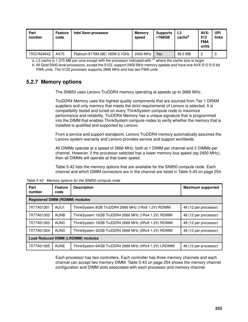
5.2.7 Memory options
The SN850 uses Lenovo TruDDR4 memory operating at speeds up to 2666 MHz.
TruDDR4 Memory uses the highest quality components that are sourced from Tier 1 DRAM suppliers and only memory that meets the strict requirements of Lenovo is selected. It is compatibility tested and tuned on every ThinkSystem compute node to maximize performance and reliability. TruDDR4 Memory has a unique signature that is programmed into the DIMM that enables ThinkSystem compute nodes to verify whether the memory that is installed is qualified and supported by Lenovo.
From a service and support standpoint, Lenovo TruDDR4 memory automatically assumes the Lenovo system warranty and Lenovo provides service and support worldwide.
All DIMMs operate at a speed of 2666 MHz, both at 1 DIMM per channel and 2 DIMMs per channel. However, if the processor selected has a lower memory bus speed (eg 2400 MHz), then all DIMMs will operate at that lower speed.
Table 5-42 lists the memory options that are available for the SN850 compute node. Each channel and which DIMM connectors are in the channel are listed in Table 5-43 on page 254.
Table 5-42 Memory options for the SN850 compute node
Each processor has two controllers. Each controller has three memory channels and each channel can accept two memory DIMM. Table 5-43 on page 254 shows the memory channel configuration and DIMM slots associated with each processor and memory channel.
7XG7A04642 AX75 Platinum 8176M 28C 165W 2.1GHz 2400 MHz Yes 38.5 MB 2 3
a. L3 cache is 1.375 MB per core except with the processor indicated with ** where the cache size is largerb. All Gold 5000-level processors, except the 5122, support 2400 MHz memory speeds and have one AVX-512 512-bit
FMA units. The 5122 processor supports 2666 MHz and has two FMA units
Partnumber
Featurecode
Intel Xeon processor Memoryspeed
Supports>768GB
L3cachea
AVX-512FMAunits
UPIlinks
Partnumber
Feature code
Description Maximum supported
Registered DIMM (RDIMM) modules
7X77A01301 AUU1 ThinkSystem 8GB TruDDR4 2666 MHz (1Rx8 1.2V) RDIMM 48 (12 per processor)
7X77A01302 AUNB ThinkSystem 16GB TruDDR4 2666 MHz (1Rx4 1.2V) RDIMM 48 (12 per processor)
7X77A01303 AUNC ThinkSystem 16GB TruDDR4 2666 MHz (2Rx8 1.2V) RDIMM 48 (12 per processor)
7X77A01304 AUND ThinkSystem 32GB TruDDR4 2666 MHz (2Rx4 1.2V) RDIMM 48 (12 per processor)
Load Reduced DIMM (LRDIMM) modules
7X77A01305 AUNE ThinkSystem 64GB TruDDR4 2666 MHz (4Rx4 1.2V) LRDIMM 48 (12 per processor)
253
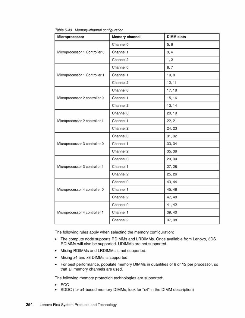
Table 5-43 Memory-channel configuration
The following rules apply when selecting the memory configuration:
� The compute node supports RDIMMs and LRDIMMs. Once available from Lenovo, 3DS RDIMMs will also be supported. UDIMMs are not supported.
� Mixing RDIMMs and LRDIMMs is not supported.
� Mixing x4 and x8 DIMMs is supported.
� For best performance, populate memory DIMMs in quantities of 6 or 12 per processor, so that all memory channels are used.
The following memory protection technologies are supported:
� ECC� SDDC (for x4-based memory DIMMs; look for “x4” in the DIMM description)
Microprocessor Memory channel DIMM slots
Microprocessor 1 Controller 0
Channel 0 5, 6
Channel 1 3, 4
Channel 2 1, 2
Microprocessor 1 Controller 1
Channel 0 8, 7
Channel 1 10, 9
Channel 2 12, 11
Microprocessor 2 controller 0
Channel 0 17, 18
Channel 1 15, 16
Channel 2 13, 14
Microprocessor 2 controller 1
Channel 0 20, 19
Channel 1 22, 21
Channel 2 24, 23
Microprocessor 3 controller 0
Channel 0 31, 32
Channel 1 33, 34
Channel 2 35, 36
Microprocessor 3 controller 1
Channel 0 29, 30
Channel 1 27, 28
Channel 2 25, 26
Microprocessor 4 controller 0
Channel 0 43, 44
Channel 1 45, 46
Channel 2 47, 48
Microprocessor 4 controller 1
Channel 0 41, 42
Channel 1 39, 40
Channel 2 37, 38
254 Lenovo Flex System Products and Technology
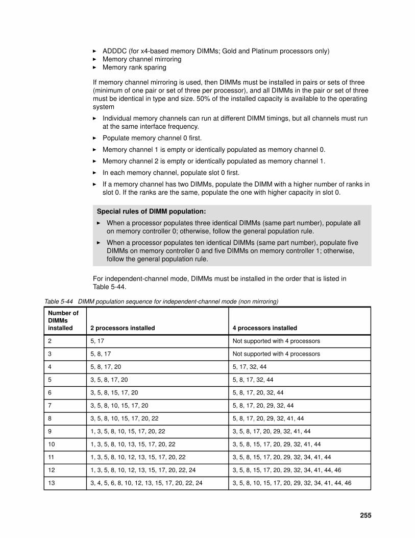
� ADDDC (for x4-based memory DIMMs; Gold and Platinum processors only)� Memory channel mirroring� Memory rank sparing
If memory channel mirroring is used, then DIMMs must be installed in pairs or sets of three (minimum of one pair or set of three per processor), and all DIMMs in the pair or set of three must be identical in type and size. 50% of the installed capacity is available to the operating system
� Individual memory channels can run at different DIMM timings, but all channels must run at the same interface frequency.
� Populate memory channel 0 first.
� Memory channel 1 is empty or identically populated as memory channel 0.
� Memory channel 2 is empty or identically populated as memory channel 1.
� In each memory channel, populate slot 0 first.
� If a memory channel has two DIMMs, populate the DIMM with a higher number of ranks in slot 0. If the ranks are the same, populate the one with higher capacity in slot 0.
For independent-channel mode, DIMMs must be installed in the order that is listed in Table 5-44.
Table 5-44 DIMM population sequence for independent-channel mode (non mirroring)
Special rules of DIMM population:
� When a processor populates three identical DIMMs (same part number), populate all on memory controller 0; otherwise, follow the general population rule.
� When a processor populates ten identical DIMMs (same part number), populate five DIMMs on memory controller 0 and five DIMMs on memory controller 1; otherwise, follow the general population rule.
Number ofDIMMsinstalled 2 processors installed 4 processors installed
2 5, 17 Not supported with 4 processors
3 5, 8, 17 Not supported with 4 processors
4 5, 8, 17, 20 5, 17, 32, 44
5 3, 5, 8, 17, 20 5, 8, 17, 32, 44
6 3, 5, 8, 15, 17, 20 5, 8, 17, 20, 32, 44
7 3, 5, 8, 10, 15, 17, 20 5, 8, 17, 20, 29, 32, 44
8 3, 5, 8, 10, 15, 17, 20, 22 5, 8, 17, 20, 29, 32, 41, 44
9 1, 3, 5, 8, 10, 15, 17, 20, 22 3, 5, 8, 17, 20, 29, 32, 41, 44
10 1, 3, 5, 8, 10, 13, 15, 17, 20, 22 3, 5, 8, 15, 17, 20, 29, 32, 41, 44
11 1, 3, 5, 8, 10, 12, 13, 15, 17, 20, 22 3, 5, 8, 15, 17, 20, 29, 32, 34, 41, 44
12 1, 3, 5, 8, 10, 12, 13, 15, 17, 20, 22, 24 3, 5, 8, 15, 17, 20, 29, 32, 34, 41, 44, 46
13 3, 4, 5, 6, 8, 10, 12, 13, 15, 17, 20, 22, 24 3, 5, 8, 10, 15, 17, 20, 29, 32, 34, 41, 44, 46
255
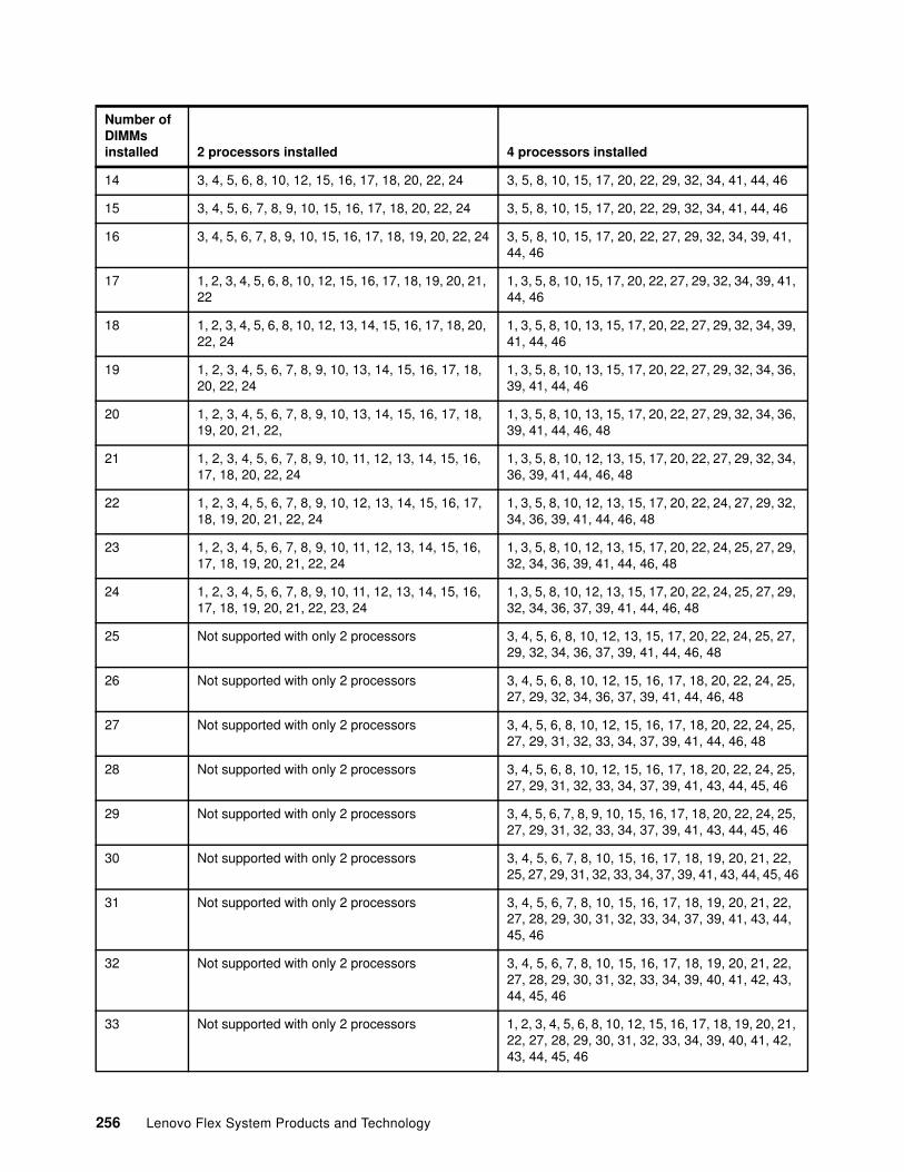
14 3, 4, 5, 6, 8, 10, 12, 15, 16, 17, 18, 20, 22, 24 3, 5, 8, 10, 15, 17, 20, 22, 29, 32, 34, 41, 44, 46
15 3, 4, 5, 6, 7, 8, 9, 10, 15, 16, 17, 18, 20, 22, 24 3, 5, 8, 10, 15, 17, 20, 22, 29, 32, 34, 41, 44, 46
16 3, 4, 5, 6, 7, 8, 9, 10, 15, 16, 17, 18, 19, 20, 22, 24 3, 5, 8, 10, 15, 17, 20, 22, 27, 29, 32, 34, 39, 41, 44, 46
17 1, 2, 3, 4, 5, 6, 8, 10, 12, 15, 16, 17, 18, 19, 20, 21, 22
1, 3, 5, 8, 10, 15, 17, 20, 22, 27, 29, 32, 34, 39, 41, 44, 46
18 1, 2, 3, 4, 5, 6, 8, 10, 12, 13, 14, 15, 16, 17, 18, 20, 22, 24
1, 3, 5, 8, 10, 13, 15, 17, 20, 22, 27, 29, 32, 34, 39, 41, 44, 46
19 1, 2, 3, 4, 5, 6, 7, 8, 9, 10, 13, 14, 15, 16, 17, 18, 20, 22, 24
1, 3, 5, 8, 10, 13, 15, 17, 20, 22, 27, 29, 32, 34, 36, 39, 41, 44, 46
20 1, 2, 3, 4, 5, 6, 7, 8, 9, 10, 13, 14, 15, 16, 17, 18, 19, 20, 21, 22,
1, 3, 5, 8, 10, 13, 15, 17, 20, 22, 27, 29, 32, 34, 36, 39, 41, 44, 46, 48
21 1, 2, 3, 4, 5, 6, 7, 8, 9, 10, 11, 12, 13, 14, 15, 16, 17, 18, 20, 22, 24
1, 3, 5, 8, 10, 12, 13, 15, 17, 20, 22, 27, 29, 32, 34, 36, 39, 41, 44, 46, 48
22 1, 2, 3, 4, 5, 6, 7, 8, 9, 10, 12, 13, 14, 15, 16, 17, 18, 19, 20, 21, 22, 24
1, 3, 5, 8, 10, 12, 13, 15, 17, 20, 22, 24, 27, 29, 32, 34, 36, 39, 41, 44, 46, 48
23 1, 2, 3, 4, 5, 6, 7, 8, 9, 10, 11, 12, 13, 14, 15, 16, 17, 18, 19, 20, 21, 22, 24
1, 3, 5, 8, 10, 12, 13, 15, 17, 20, 22, 24, 25, 27, 29, 32, 34, 36, 39, 41, 44, 46, 48
24 1, 2, 3, 4, 5, 6, 7, 8, 9, 10, 11, 12, 13, 14, 15, 16, 17, 18, 19, 20, 21, 22, 23, 24
1, 3, 5, 8, 10, 12, 13, 15, 17, 20, 22, 24, 25, 27, 29, 32, 34, 36, 37, 39, 41, 44, 46, 48
25 Not supported with only 2 processors 3, 4, 5, 6, 8, 10, 12, 13, 15, 17, 20, 22, 24, 25, 27, 29, 32, 34, 36, 37, 39, 41, 44, 46, 48
26 Not supported with only 2 processors 3, 4, 5, 6, 8, 10, 12, 15, 16, 17, 18, 20, 22, 24, 25, 27, 29, 32, 34, 36, 37, 39, 41, 44, 46, 48
27 Not supported with only 2 processors 3, 4, 5, 6, 8, 10, 12, 15, 16, 17, 18, 20, 22, 24, 25, 27, 29, 31, 32, 33, 34, 37, 39, 41, 44, 46, 48
28 Not supported with only 2 processors 3, 4, 5, 6, 8, 10, 12, 15, 16, 17, 18, 20, 22, 24, 25, 27, 29, 31, 32, 33, 34, 37, 39, 41, 43, 44, 45, 46
29 Not supported with only 2 processors 3, 4, 5, 6, 7, 8, 9, 10, 15, 16, 17, 18, 20, 22, 24, 25, 27, 29, 31, 32, 33, 34, 37, 39, 41, 43, 44, 45, 46
30 Not supported with only 2 processors 3, 4, 5, 6, 7, 8, 10, 15, 16, 17, 18, 19, 20, 21, 22, 25, 27, 29, 31, 32, 33, 34, 37, 39, 41, 43, 44, 45, 46
31 Not supported with only 2 processors 3, 4, 5, 6, 7, 8, 10, 15, 16, 17, 18, 19, 20, 21, 22, 27, 28, 29, 30, 31, 32, 33, 34, 37, 39, 41, 43, 44, 45, 46
32 Not supported with only 2 processors 3, 4, 5, 6, 7, 8, 10, 15, 16, 17, 18, 19, 20, 21, 22, 27, 28, 29, 30, 31, 32, 33, 34, 39, 40, 41, 42, 43, 44, 45, 46
33 Not supported with only 2 processors 1, 2, 3, 4, 5, 6, 8, 10, 12, 15, 16, 17, 18, 19, 20, 21, 22, 27, 28, 29, 30, 31, 32, 33, 34, 39, 40, 41, 42, 43, 44, 45, 46
Number ofDIMMsinstalled 2 processors installed 4 processors installed
256 Lenovo Flex System Products and Technology

34 Not supported with only 2 processors 1, 2, 3, 4, 5, 6, 8, 10, 12, 13, 14, 15, 16, 17, 18, 20, 22, 24, 27, 28, 29, 30, 31, 32, 33, 34, 39, 40, 41, 42, 43, 44, 45, 46
35 Not supported with only 2 processors 1, 2, 3, 4, 5, 6, 8, 10, 12, 13, 14, 15, 16, 17, 18, 20, 22, 24, 25, 27, 29, 31, 32, 33, 34, 35, 36, 39, 40, 41, 42, 43, 44, 45, 46
36 Not supported with only 2 processors 1, 2, 3, 4, 5, 6, 8, 10, 12, 13, 14, 15, 16, 17, 18, 20, 22, 24, 25, 27, 29, 31, 32, 33, 34, 35, 36, 37, 39, 41, 43, 44, 45, 46, 47, 48
37 Not supported with only 2 processors 1, 2, 3, 4, 5, 6, 7, 8, 9, 10, 13, 14, 15, 16, 17, 18, 20, 22, 24, 25, 27, 29, 31, 32, 33, 34, 35, 36, 37, 39, 41, 43, 44, 45, 46, 47, 48
38 Not supported with only 2 processors 1, 2, 3, 4, 5, 6, 7, 8, 9, 10, 13, 14, 15, 16, 17, 18, 19, 20, 21, 22, 25, 27, 29, 31, 32, 33, 34, 35, 36, 37, 39, 41, 43, 44, 45, 46, 47, 48
39 Not supported with only 2 processors 1, 2, 3, 4, 5, 6, 7, 8, 9, 10, 13, 14, 15, 16, 17, 18, 19, 20, 21, 22, 27, 28, 29, 30, 31, 32, 33, 34, 35, 36, 37, 39, 41, 43, 44, 45, 46, 47, 48
40 Not supported with only 2 processors 1, 2, 3, 4, 5, 6, 7, 8, 9, 10, 13, 14, 15, 16, 17, 18, 19, 20, 21, 22, 27, 28, 29, 30, 31, 32, 33, 34, 35, 36, 39, 40, 41, 42, 43, 44, 45, 46, 47, 48
41 Not supported with only 2 processors 1, 2, 3, 4, 5, 6, 7, 8, 9, 10, 11, 12, 13, 14, 15, 16, 17, 18, 20, 22, 24, 27, 28, 29, 30, 31, 32, 33, 34, 35, 36, 39, 40, 41, 42, 43, 44, 45, 46, 47, 48
42 Not supported with only 2 processors 1, 2, 3, 4, 5, 6, 7, 8, 9, 10, 11, 12, 13, 14, 15, 16, 17, 18, 19, 20, 21, 22, 23, 24, 25, 27, 29, 31, 32, 33, 34, 35, 36, 37, 39, 41, 43, 44, 45, 46, 47, 48
43 Not supported with only 2 processors 1, 2, 3, 4, 5, 6, 7, 8, 9, 10, 11, 12, 13, 14, 15, 16, 17, 18, 19, 20, 21, 22, 23, 24, 27, 28, 29, 30, 31, 32, 33, 34, 35, 36, 37, 39, 41, 43, 44, 45, 46, 47, 48
44 Not supported with only 2 processors 1, 2, 3, 4, 5, 6, 7, 8, 9, 10, 12, 13, 14, 15, 16, 17, 18, 19, 20, 21, 22, 24, 25, 27, 28, 29, 30, 31, 32, 33, 34, 35, 36, 37, 39, 40, 41, 42, 43, 44, 45, 46, 47, 48
45 Not supported with only 2 processors 1, 2, 3, 4, 5, 6, 7, 8, 9, 10, 11, 12, 13, 14, 15, 16, 17, 18, 19, 20, 21, 22, 23, 24, 25, 26, 27, 28, 29, 30, 31, 32, 33, 34, 35, 36, 37, 39, 41, 43, 44, 45, 46, 47, 48
46 Not supported with only 2 processors 1, 2, 3, 4, 5, 6, 7, 8, 9, 10, 11, 12, 13, 14, 15, 16, 17, 18, 19, 20, 21, 22, 23, 24, 25, 26, 27, 28, 29, 30, 31, 32, 33, 34, 35, 36, 39, 40, 41, 42, 43, 44, 45, 46, 47, 48
47 Not supported with only 2 processors 1, 2, 3, 4, 5, 6, 7, 8, 9, 10, 11, 12, 13, 14, 15, 16, 17, 18, 19, 20, 21, 22, 23, 24, 25, 26, 27, 28, 29, 30, 31, 32, 33, 34, 35, 36, 37, 39, 40, 41, 42, 43, 44, 45, 46, 47, 48
Number ofDIMMsinstalled 2 processors installed 4 processors installed
257
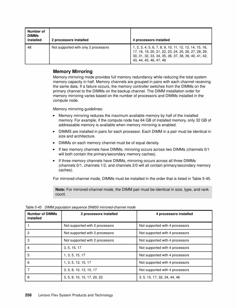
Memory MirroringMemory-mirroring mode provides full memory redundancy while reducing the total system memory capacity in half. Memory channels are grouped in pairs with each channel receiving the same data. If a failure occurs, the memory controller switches from the DIMMs on the primary channel to the DIMMs on the backup channel. The DIMM installation order for memory mirroring varies based on the number of processors and DIMMs installed in the compute node.
Memory mirroring guidelines:
� Memory mirroring reduces the maximum available memory by half of the installed memory. For example, if the compute node has 64 GB of installed memory, only 32 GB of addressable memory is available when memory mirroring is enabled.
� DIMMS are installed in pairs for each processor. Each DIMM in a pair must be identical in size and architecture.
� DIMMs on each memory channel must be of equal density.
� If two memory channels have DIMMs, mirroring occurs across two DIMMs (channels 0/1 will both contain the primary/secondary memory caches).
� If three memory channels have DIMMs, mirroring occurs across all three DIMMs (channels 0/1, channels 1/2, and channels 2/0 will all contain primary/secondary memory caches).
For mirrored-channel mode, DIMMs must be installed in the order that is listed in Table 5-45.
Table 5-45 DIMM population sequence SN850 mirrored-channel mode
48 Not supported with only 2 processors 1, 2, 3, 4, 5, 6, 7, 8, 9, 10, 11, 12, 13, 14, 15, 16, 17, 18, 19, 20, 21, 22, 23, 24, 25, 26, 27, 28, 29, 30, 31, 32, 33, 34, 35, 36, 37, 38, 39, 40, 41, 42, 43, 44, 45, 46, 47, 48
Number ofDIMMsinstalled 2 processors installed 4 processors installed
Note: For mirrored-channel mode, the DIMM pair must be identical in size, type, and rank count.
Number of DIMMsinstalled
2 processors installed 4 processors installed
1 Not supported with 2 processors Not supported with 4 processors
2 Not supported with 2 processors Not supported with 4 processors
3 Not supported with 2 processors Not supported with 4 processors
4 3, 5, 15, 17 Not supported with 4 processors
5 1, 3, 5, 15, 17 Not supported with 4 processors
6 1, 3, 5, 13, 15, 17 Not supported with 4 processors
7 3, 5, 8, 10, 13, 15, 17 Not supported with 4 processors
8 3, 5, 8, 10, 15, 17, 20, 22 3, 5, 15, 17, 32, 34, 44, 46
258 Lenovo Flex System Products and Technology
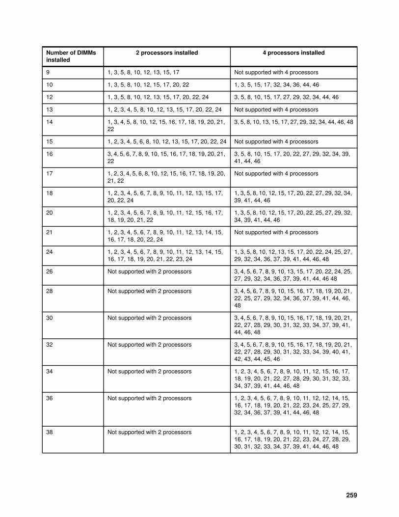
9 1, 3, 5, 8, 10, 12, 13, 15, 17 Not supported with 4 processors
10 1, 3, 5, 8, 10, 12, 15, 17, 20, 22 1, 3, 5, 15, 17, 32, 34, 36, 44, 46
12 1, 3, 5, 8, 10, 12, 13, 15, 17, 20, 22, 24 3, 5, 8, 10, 15, 17, 27, 29, 32, 34, 44, 46
13 1, 2, 3, 4, 5, 8, 10, 12, 13, 15, 17, 20, 22, 24 Not supported with 4 processors
14 1, 3, 4, 5, 8, 10, 12, 15, 16, 17, 18, 19, 20, 21, 22
3, 5, 8, 10, 13, 15, 17, 27, 29, 32, 34, 44, 46, 48
15 1, 2, 3, 4, 5, 6, 8, 10, 12, 13, 15, 17, 20, 22, 24 Not supported with 4 processors
16 3, 4, 5, 6, 7, 8, 9, 10, 15, 16, 17, 18, 19, 20, 21, 22
3, 5, 8, 10, 15, 17, 20, 22, 27, 29, 32, 34, 39, 41, 44, 46
17 1, 2, 3, 4, 5, 6, 8, 10, 12, 15, 16, 17, 18, 19, 20, 21, 22
Not supported with 4 processors
18 1, 2, 3, 4, 5, 6, 7, 8, 9, 10, 11, 12, 13, 15, 17, 20, 22, 24
1, 3, 5, 8, 10, 12, 15, 17, 20, 22, 27, 29, 32, 34, 39, 41, 44, 46
20 1, 2, 3, 4, 5, 6, 7, 8, 9, 10, 11, 12, 15, 16, 17, 18, 19, 20, 21, 22
1, 3, 5, 8, 10, 12, 15, 17, 20, 22, 25, 27, 29, 32, 34, 39, 41, 44, 46
21 1, 2, 3, 4, 5, 6, 7, 8, 9, 10, 11, 12, 13, 14, 15, 16, 17, 18, 20, 22, 24
Not supported with 4 processors
24 1, 2, 3, 4, 5, 6, 7, 8, 9, 10, 11, 12, 13, 14, 15, 16, 17, 18, 19, 20, 21, 22, 23, 24
1, 3, 5, 8, 10, 12, 13, 15, 17, 20, 22, 24, 25, 27, 29, 32, 34, 36, 37, 39, 41, 44, 46, 48
26 Not supported with 2 processors 3, 4, 5, 6, 7, 8, 9, 10, 13, 15, 17, 20, 22, 24, 25, 27, 29, 32, 34, 36, 37, 39, 41, 44, 46 48
28 Not supported with 2 processors 3, 4, 5, 6, 7, 8, 9, 10, 15, 16, 17, 18, 19, 20, 21, 22, 25, 27, 29, 32, 34, 36, 37, 39, 41, 44, 46, 48
30 Not supported with 2 processors 3, 4, 5, 6, 7, 8, 9, 10, 15, 16, 17, 18, 19, 20, 21, 22, 27, 28, 29, 30, 31, 32, 33, 34, 37, 39, 41, 44, 46, 48
32 Not supported with 2 processors 3, 4, 5, 6, 7, 8, 9, 10, 15, 16, 17, 18, 19, 20, 21, 22, 27, 28, 29, 30, 31, 32, 33, 34, 39, 40, 41, 42, 43, 44, 45, 46
34 Not supported with 2 processors 1, 2, 3, 4, 5, 6, 7, 8, 9, 10, 11, 12, 15, 16, 17, 18, 19, 20, 21, 22, 27, 28, 29, 30, 31, 32, 33, 34, 37, 39, 41, 44, 46, 48
36 Not supported with 2 processors 1, 2, 3, 4, 5, 6, 7, 8, 9, 10, 11, 12, 12, 14, 15, 16, 17, 18, 19, 20, 21, 22, 23, 24, 25, 27, 29, 32, 34, 36, 37, 39, 41, 44, 46, 48
38 Not supported with 2 processors 1, 2, 3, 4, 5, 6, 7, 8, 9, 10, 11, 12, 12, 14, 15, 16, 17, 18, 19, 20, 21, 22, 23, 24, 27, 28, 29, 30, 31, 32, 33, 34, 37, 39, 41, 44, 46, 48
Number of DIMMsinstalled
2 processors installed 4 processors installed
259
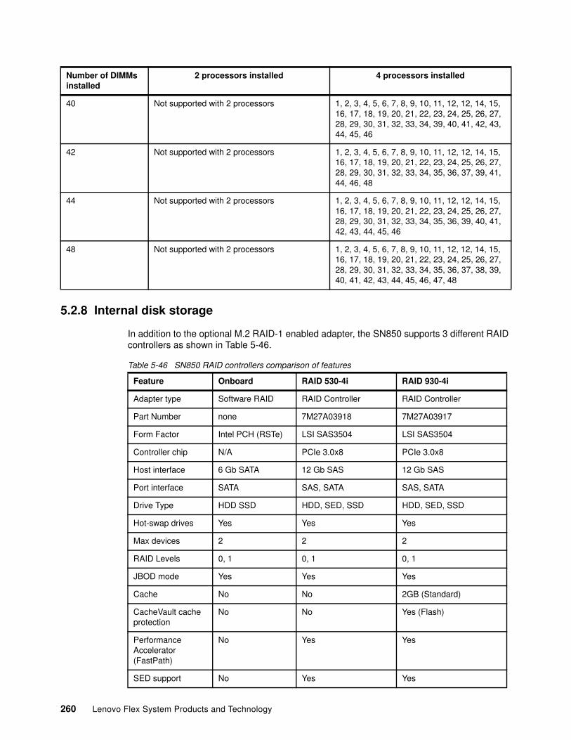
5.2.8 Internal disk storage
In addition to the optional M.2 RAID-1 enabled adapter, the SN850 supports 3 different RAID controllers as shown in Table 5-46.
Table 5-46 SN850 RAID controllers comparison of features
40 Not supported with 2 processors 1, 2, 3, 4, 5, 6, 7, 8, 9, 10, 11, 12, 12, 14, 15, 16, 17, 18, 19, 20, 21, 22, 23, 24, 25, 26, 27, 28, 29, 30, 31, 32, 33, 34, 39, 40, 41, 42, 43, 44, 45, 46
42 Not supported with 2 processors 1, 2, 3, 4, 5, 6, 7, 8, 9, 10, 11, 12, 12, 14, 15, 16, 17, 18, 19, 20, 21, 22, 23, 24, 25, 26, 27, 28, 29, 30, 31, 32, 33, 34, 35, 36, 37, 39, 41, 44, 46, 48
44 Not supported with 2 processors 1, 2, 3, 4, 5, 6, 7, 8, 9, 10, 11, 12, 12, 14, 15, 16, 17, 18, 19, 20, 21, 22, 23, 24, 25, 26, 27, 28, 29, 30, 31, 32, 33, 34, 35, 36, 39, 40, 41, 42, 43, 44, 45, 46
48 Not supported with 2 processors 1, 2, 3, 4, 5, 6, 7, 8, 9, 10, 11, 12, 12, 14, 15, 16, 17, 18, 19, 20, 21, 22, 23, 24, 25, 26, 27, 28, 29, 30, 31, 32, 33, 34, 35, 36, 37, 38, 39, 40, 41, 42, 43, 44, 45, 46, 47, 48
Number of DIMMsinstalled
2 processors installed 4 processors installed
Feature Onboard RAID 530-4i RAID 930-4i
Adapter type Software RAID RAID Controller RAID Controller
Part Number none 7M27A03918 7M27A03917
Form Factor Intel PCH (RSTe) LSI SAS3504 LSI SAS3504
Controller chip N/A PCIe 3.0x8 PCIe 3.0x8
Host interface 6 Gb SATA 12 Gb SAS 12 Gb SAS
Port interface SATA SAS, SATA SAS, SATA
Drive Type HDD SSD HDD, SED, SSD HDD, SED, SSD
Hot-swap drives Yes Yes Yes
Max devices 2 2 2
RAID Levels 0, 1 0, 1 0, 1
JBOD mode Yes Yes Yes
Cache No No 2GB (Standard)
CacheVault cache protection
No No Yes (Flash)
Performance Accelerator (FastPath)
No Yes Yes
SED support No Yes Yes
260 Lenovo Flex System Products and Technology
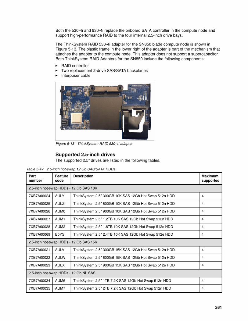
Both the 530-4i and 930-4i replace the onboard SATA controller in the compute node and support high-performance RAID to the four internal 2.5-inch drive bays.
The ThinkSystem RAID 530-4i adapter for the SN850 blade compute node is shown in Figure 5-13. The plastic frame in the lower right of the adapter is part of the mechanism that attaches the adapter to the compute node. This adapter does not support a supercapacitor. Both ThinkSystem RAID Adapters for the SN850 include the following components:
� RAID controller� Two replacement 2-drive SAS/SATA backplanes� Interposer cable
Figure 5-13 ThinkSystem RAID 530-4i adapter
Supported 2.5-inch drivesThe supported 2.5” drives are listed in the following tables.
Table 5-47 2.5-inch hot-swap 12 Gb SAS/SATA HDDs
Partnumber
Featurecode
Description Maximumsupported
2.5-inch hot-swap HDDs - 12 Gb SAS 10K
7XB7A00024 AULY ThinkSystem 2.5" 300GB 10K SAS 12Gb Hot Swap 512n HDD 4
7XB7A00025 AULZ ThinkSystem 2.5" 600GB 10K SAS 12Gb Hot Swap 512n HDD 4
7XB7A00026 AUM0 ThinkSystem 2.5" 900GB 10K SAS 12Gb Hot Swap 512n HDD 4
7XB7A00027 AUM1 ThinkSystem 2.5" 1.2TB 10K SAS 12Gb Hot Swap 512n HDD 4
7XB7A00028 AUM2 ThinkSystem 2.5" 1.8TB 10K SAS 12Gb Hot Swap 512e HDD 4
7XB7A00069 B0YS ThinkSystem 2.5" 2.4TB 10K SAS 12Gb Hot Swap 512e HDD 4
2.5-inch hot-swap HDDs - 12 Gb SAS 15K
7XB7A00021 AULV ThinkSystem 2.5" 300GB 15K SAS 12Gb Hot Swap 512n HDD 4
7XB7A00022 AULW ThinkSystem 2.5" 600GB 15K SAS 12Gb Hot Swap 512n HDD 4
7XB7A00023 AULX ThinkSystem 2.5" 900GB 15K SAS 12Gb Hot Swap 512e HDD 4
2.5-inch hot-swap HDDs - 12 Gb NL SAS
7XB7A00034 AUM6 ThinkSystem 2.5" 1TB 7.2K SAS 12Gb Hot Swap 512n HDD 4
7XB7A00035 AUM7 ThinkSystem 2.5" 2TB 7.2K SAS 12Gb Hot Swap 512n HDD 4
261
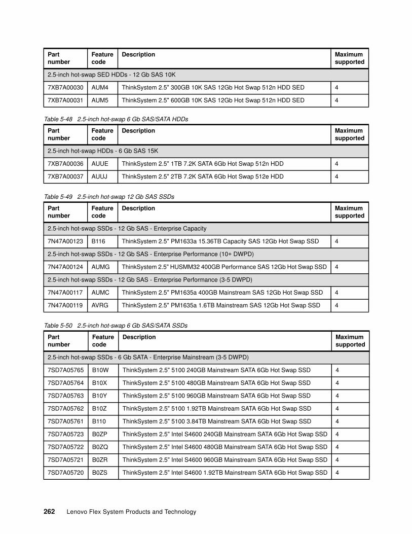
Table 5-48 2.5-inch hot-swap 6 Gb SAS/SATA HDDs
Table 5-49 2.5-inch hot-swap 12 Gb SAS SSDs
Table 5-50 2.5-inch hot-swap 6 Gb SAS/SATA SSDs
2.5-inch hot-swap SED HDDs - 12 Gb SAS 10K
7XB7A00030 AUM4 ThinkSystem 2.5" 300GB 10K SAS 12Gb Hot Swap 512n HDD SED 4
7XB7A00031 AUM5 ThinkSystem 2.5" 600GB 10K SAS 12Gb Hot Swap 512n HDD SED 4
Partnumber
Featurecode
Description Maximumsupported
2.5-inch hot-swap HDDs - 6 Gb SAS 15K
7XB7A00036 AUUE ThinkSystem 2.5" 1TB 7.2K SATA 6Gb Hot Swap 512n HDD 4
7XB7A00037 AUUJ ThinkSystem 2.5" 2TB 7.2K SATA 6Gb Hot Swap 512e HDD 4
Partnumber
Featurecode
Description Maximumsupported
2.5-inch hot-swap SSDs - 12 Gb SAS - Enterprise Capacity
7N47A00123 B116 ThinkSystem 2.5" PM1633a 15.36TB Capacity SAS 12Gb Hot Swap SSD 4
2.5-inch hot-swap SSDs - 12 Gb SAS - Enterprise Performance (10+ DWPD)
7N47A00124 AUMG ThinkSystem 2.5" HUSMM32 400GB Performance SAS 12Gb Hot Swap SSD 4
2.5-inch hot-swap SSDs - 12 Gb SAS - Enterprise Performance (3-5 DWPD)
7N47A00117 AUMC ThinkSystem 2.5" PM1635a 400GB Mainstream SAS 12Gb Hot Swap SSD 4
7N47A00119 AVRG ThinkSystem 2.5" PM1635a 1.6TB Mainstream SAS 12Gb Hot Swap SSD 4
Partnumber
Featurecode
Description Maximumsupported
2.5-inch hot-swap SSDs - 6 Gb SATA - Enterprise Mainstream (3-5 DWPD)
7SD7A05765 B10W ThinkSystem 2.5" 5100 240GB Mainstream SATA 6Gb Hot Swap SSD 4
7SD7A05764 B10X ThinkSystem 2.5" 5100 480GB Mainstream SATA 6Gb Hot Swap SSD 4
7SD7A05763 B10Y ThinkSystem 2.5" 5100 960GB Mainstream SATA 6Gb Hot Swap SSD 4
7SD7A05762 B10Z ThinkSystem 2.5" 5100 1.92TB Mainstream SATA 6Gb Hot Swap SSD 4
7SD7A05761 B110 ThinkSystem 2.5" 5100 3.84TB Mainstream SATA 6Gb Hot Swap SSD 4
7SD7A05723 B0ZP ThinkSystem 2.5" Intel S4600 240GB Mainstream SATA 6Gb Hot Swap SSD 4
7SD7A05722 B0ZQ ThinkSystem 2.5" Intel S4600 480GB Mainstream SATA 6Gb Hot Swap SSD 4
7SD7A05721 B0ZR ThinkSystem 2.5" Intel S4600 960GB Mainstream SATA 6Gb Hot Swap SSD 4
7SD7A05720 B0ZS ThinkSystem 2.5" Intel S4600 1.92TB Mainstream SATA 6Gb Hot Swap SSD 4
Partnumber
Featurecode
Description Maximumsupported
262 Lenovo Flex System Products and Technology
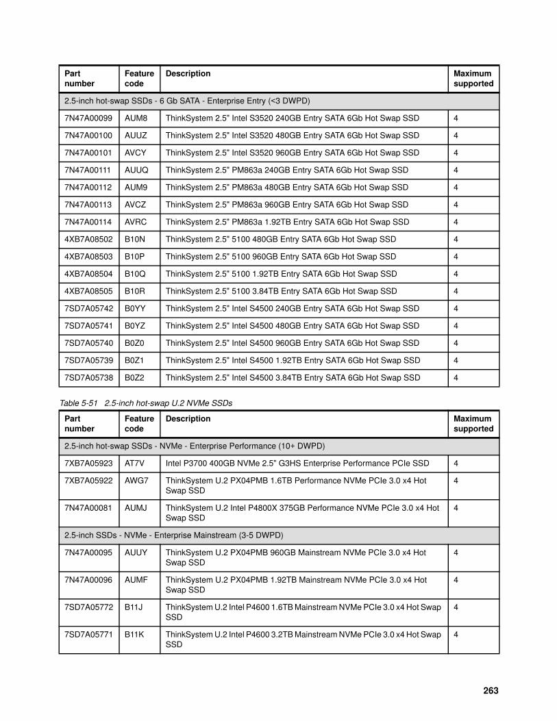
Table 5-51 2.5-inch hot-swap U.2 NVMe SSDs
2.5-inch hot-swap SSDs - 6 Gb SATA - Enterprise Entry (<3 DWPD)
7N47A00099 AUM8 ThinkSystem 2.5" Intel S3520 240GB Entry SATA 6Gb Hot Swap SSD 4
7N47A00100 AUUZ ThinkSystem 2.5" Intel S3520 480GB Entry SATA 6Gb Hot Swap SSD 4
7N47A00101 AVCY ThinkSystem 2.5" Intel S3520 960GB Entry SATA 6Gb Hot Swap SSD 4
7N47A00111 AUUQ ThinkSystem 2.5" PM863a 240GB Entry SATA 6Gb Hot Swap SSD 4
7N47A00112 AUM9 ThinkSystem 2.5" PM863a 480GB Entry SATA 6Gb Hot Swap SSD 4
7N47A00113 AVCZ ThinkSystem 2.5" PM863a 960GB Entry SATA 6Gb Hot Swap SSD 4
7N47A00114 AVRC ThinkSystem 2.5" PM863a 1.92TB Entry SATA 6Gb Hot Swap SSD 4
4XB7A08502 B10N ThinkSystem 2.5" 5100 480GB Entry SATA 6Gb Hot Swap SSD 4
4XB7A08503 B10P ThinkSystem 2.5" 5100 960GB Entry SATA 6Gb Hot Swap SSD 4
4XB7A08504 B10Q ThinkSystem 2.5" 5100 1.92TB Entry SATA 6Gb Hot Swap SSD 4
4XB7A08505 B10R ThinkSystem 2.5" 5100 3.84TB Entry SATA 6Gb Hot Swap SSD 4
7SD7A05742 B0YY ThinkSystem 2.5" Intel S4500 240GB Entry SATA 6Gb Hot Swap SSD 4
7SD7A05741 B0YZ ThinkSystem 2.5" Intel S4500 480GB Entry SATA 6Gb Hot Swap SSD 4
7SD7A05740 B0Z0 ThinkSystem 2.5" Intel S4500 960GB Entry SATA 6Gb Hot Swap SSD 4
7SD7A05739 B0Z1 ThinkSystem 2.5" Intel S4500 1.92TB Entry SATA 6Gb Hot Swap SSD 4
7SD7A05738 B0Z2 ThinkSystem 2.5" Intel S4500 3.84TB Entry SATA 6Gb Hot Swap SSD 4
Partnumber
Featurecode
Description Maximumsupported
2.5-inch hot-swap SSDs - NVMe - Enterprise Performance (10+ DWPD)
7XB7A05923 AT7V Intel P3700 400GB NVMe 2.5" G3HS Enterprise Performance PCIe SSD 4
7XB7A05922 AWG7 ThinkSystem U.2 PX04PMB 1.6TB Performance NVMe PCIe 3.0 x4 Hot Swap SSD
4
7N47A00081 AUMJ ThinkSystem U.2 Intel P4800X 375GB Performance NVMe PCIe 3.0 x4 Hot Swap SSD
4
2.5-inch SSDs - NVMe - Enterprise Mainstream (3-5 DWPD)
7N47A00095 AUUY ThinkSystem U.2 PX04PMB 960GB Mainstream NVMe PCIe 3.0 x4 Hot Swap SSD
4
7N47A00096 AUMF ThinkSystem U.2 PX04PMB 1.92TB Mainstream NVMe PCIe 3.0 x4 Hot Swap SSD
4
7SD7A05772 B11J ThinkSystem U.2 Intel P4600 1.6TB Mainstream NVMe PCIe 3.0 x4 Hot Swap SSD
4
7SD7A05771 B11K ThinkSystem U.2 Intel P4600 3.2TB Mainstream NVMe PCIe 3.0 x4 Hot Swap SSD
4
Partnumber
Featurecode
Description Maximumsupported
263
NVMe PCIe SSDs support informed hot removal and hot insertion, provided the operating system supports PCIe SSD hot-swap.
Table 5-52 M.2 Drives .
Integrated VirtualizationVMware ESXi is available as a factory installed option for the M.2 drives. Feature codes are shown in Table 5-53 there are no part numbers as these are only available as factory installed via CTO:
Table 5-53 VMware factory installed features
Alternatively, you can download supported VMware vSphere hypervisor images from the following web page and load it on the M.2 drives using the instructions provided:
http://www3.lenovo.com/us/en/data-center/solutions/alliances/vmware/#tab-VMware-tab-main-2
5.2.9 Embedded Ethernet controller
The SN850 includes an embedded 4-port 10Gb Intel controller built into the system board.
Each SN850 model that uses the embedded Intel controller has the fabric connector installed in I/O connector 3 to provide connectivity to the Flex system chassis midplane. All four 10 Gb
2.5-inch SSDs - NVMe - Enterprise Entry (<3 DWPD)
7N47A00984 AUV0 ThinkSystem U.2 PM963 1.92TB Entry NVMe PCIe 3.0 x4 Hot Swap SSD 4
7N47A00985 AUUU ThinkSystem U.2 PM963 3.84TB Entry NVMe PCIe 3.0 x4 Hot Swap SSD 4
7SD7A05779 B11C ThinkSystem U.2 Intel P4500 1.0TB Entry NVMe PCIe 3.0 x4 Hot Swap SSD 4
7SD7A05778 B11D ThinkSystem U.2 Intel P4500 2.0TB Entry NVMe PCIe 3.0 x4 Hot Swap SSD 2
7SD7A05777 B11E ThinkSystem U.2 Intel P4500 4.0TB Entry NVMe PCIe 3.0 x4 Hot Swap SSD 4
Partnumber
Featurecode
Description Maximumsupported
Partnumber
Featurecode
Description Maximumsupported
M.2 SSD- 6 Gb SATA - Enterprise Mainstream (<3 DWPD)
7N47A00129 AUUL ThinkSystem M.2 CV1 32GB SATA 6Gbps Non-Hot-Swap SSD 2
7N47A00130 AUUV ThinkSystem M.2 CV3 128GB SATA 6Gbps Non-Hot-Swap SSD 2
7SD7A05703 B11V ThinkSystem M.2 5100 480GB SATA 6Gbps Non-Hot-Swap SSD 2
Part Number Feature Code Description
CTO only AXFT VMware ESXi 6.5 (factory installed)
CTO only AXFS VMware ESXi 6.0 U3 (factory installed)
Note: The 32GB Enterprise Value USB Memory Key is not to be used for Hypervisors. It is a general use memory storage device.
264 Lenovo Flex System Products and Technology
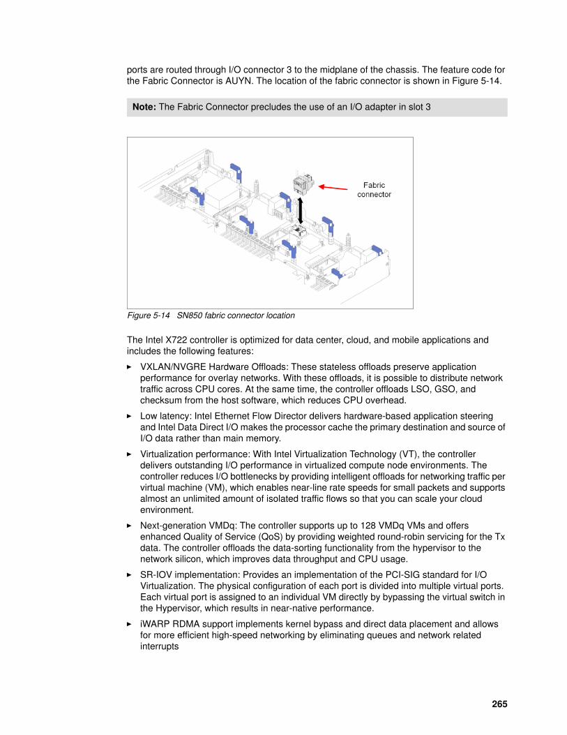
ports are routed through I/O connector 3 to the midplane of the chassis. The feature code for the Fabric Connector is AUYN. The location of the fabric connector is shown in Figure 5-14.
Figure 5-14 SN850 fabric connector location
The Intel X722 controller is optimized for data center, cloud, and mobile applications and includes the following features:
� VXLAN/NVGRE Hardware Offloads: These stateless offloads preserve application performance for overlay networks. With these offloads, it is possible to distribute network traffic across CPU cores. At the same time, the controller offloads LSO, GSO, and checksum from the host software, which reduces CPU overhead.
� Low latency: Intel Ethernet Flow Director delivers hardware-based application steering and Intel Data Direct I/O makes the processor cache the primary destination and source of I/O data rather than main memory.
� Virtualization performance: With Intel Virtualization Technology (VT), the controller delivers outstanding I/O performance in virtualized compute node environments. The controller reduces I/O bottlenecks by providing intelligent offloads for networking traffic per virtual machine (VM), which enables near-line rate speeds for small packets and supports almost an unlimited amount of isolated traffic flows so that you can scale your cloud environment.
� Next-generation VMDq: The controller supports up to 128 VMDq VMs and offers enhanced Quality of Service (QoS) by providing weighted round-robin servicing for the Tx data. The controller offloads the data-sorting functionality from the hypervisor to the network silicon, which improves data throughput and CPU usage.
� SR-IOV implementation: Provides an implementation of the PCI-SIG standard for I/O Virtualization. The physical configuration of each port is divided into multiple virtual ports. Each virtual port is assigned to an individual VM directly by bypassing the virtual switch in the Hypervisor, which results in near-native performance.
� iWARP RDMA support implements kernel bypass and direct data placement and allows for more efficient high-speed networking by eliminating queues and network related interrupts
Note: The Fabric Connector precludes the use of an I/O adapter in slot 3
265
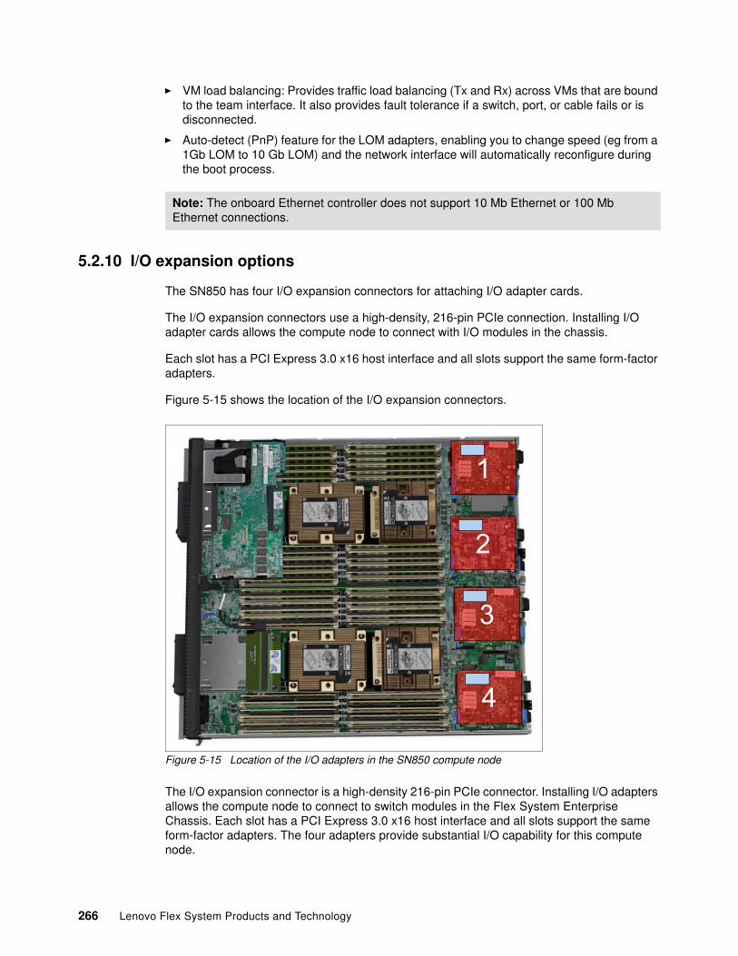
� VM load balancing: Provides traffic load balancing (Tx and Rx) across VMs that are bound to the team interface. It also provides fault tolerance if a switch, port, or cable fails or is disconnected.
� Auto-detect (PnP) feature for the LOM adapters, enabling you to change speed (eg from a 1Gb LOM to 10 Gb LOM) and the network interface will automatically reconfigure during the boot process.
5.2.10 I/O expansion options
The SN850 has four I/O expansion connectors for attaching I/O adapter cards.
The I/O expansion connectors use a high-density, 216-pin PCIe connection. Installing I/O adapter cards allows the compute node to connect with I/O modules in the chassis.
Each slot has a PCI Express 3.0 x16 host interface and all slots support the same form-factor adapters.
Figure 5-15 shows the location of the I/O expansion connectors.
Figure 5-15 Location of the I/O adapters in the SN850 compute node
The I/O expansion connector is a high-density 216-pin PCIe connector. Installing I/O adapters allows the compute node to connect to switch modules in the Flex System Enterprise Chassis. Each slot has a PCI Express 3.0 x16 host interface and all slots support the same form-factor adapters. The four adapters provide substantial I/O capability for this compute node.
Note: The onboard Ethernet controller does not support 10 Mb Ethernet or 100 Mb Ethernet connections.
1
2
3
4
266 Lenovo Flex System Products and Technology
All I/O adapters are the same shape and can be used in any available slot. A compatible switch or pass-through module must be installed in the corresponding I/O bays in the chassis, as listed in Table 5-54. Installing two switches means that all ports of the adapter are enabled, which improves performance and network availability.
Table 5-54 Adapter to I/O bay correspondence
I/O adapter slot in the SN850 Port on the adapter Corresponding I/O module bay in the chassis
Slot 1 Port 1 Module bay 1
Port 2 Module bay 2
Port 3 (for 4-port cards) Module bay 1
Port 4 (for 4-port cards) Module bay 2
Slot 2 Port 1 Module bay 3
Port 2 Module bay 4
Port 3 (for 4-port cards) Module bay 3
Port 4 (for 4-port cards) Module bay 4
Slot 3 Port 1 Module bay 1
Port 2 Module bay 2
Port 3 (for 4-port cards) Module bay 1
Port 4 (for 4-port cards) Module bay 2
Slot 4 Port 1 Module bay 3
Port 2 Module bay 4
Port 3 (for 4-port cards) Module bay 3
Port 4 (for 4-port cards) Module bay 4
267
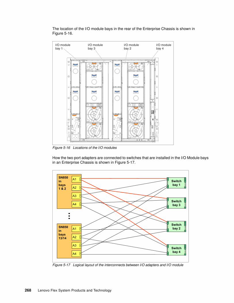
The location of the I/O module bays in the rear of the Enterprise Chassis is shown in Figure 5-16.
Figure 5-16 Locations of the I/O modules
How the two port adapters are connected to switches that are installed in the I/O Module bays in an Enterprise Chassis is shown in Figure 5-17.
Figure 5-17 Logical layout of the interconnects between I/O adapters and I/O module
I/O modulebay 1
I/O modulebay 3
I/O modulebay 2
I/O modulebay 4
SN850inbays1 & 2
A1
A2
A3
A4
Switchbay 1
... ...
Switchbay 3
... ...
Switchbay 2
... ...
Switchbay 4
... ...
SN850inbays13/14
A1
A2
A3
A4
268 Lenovo Flex System Products and Technology
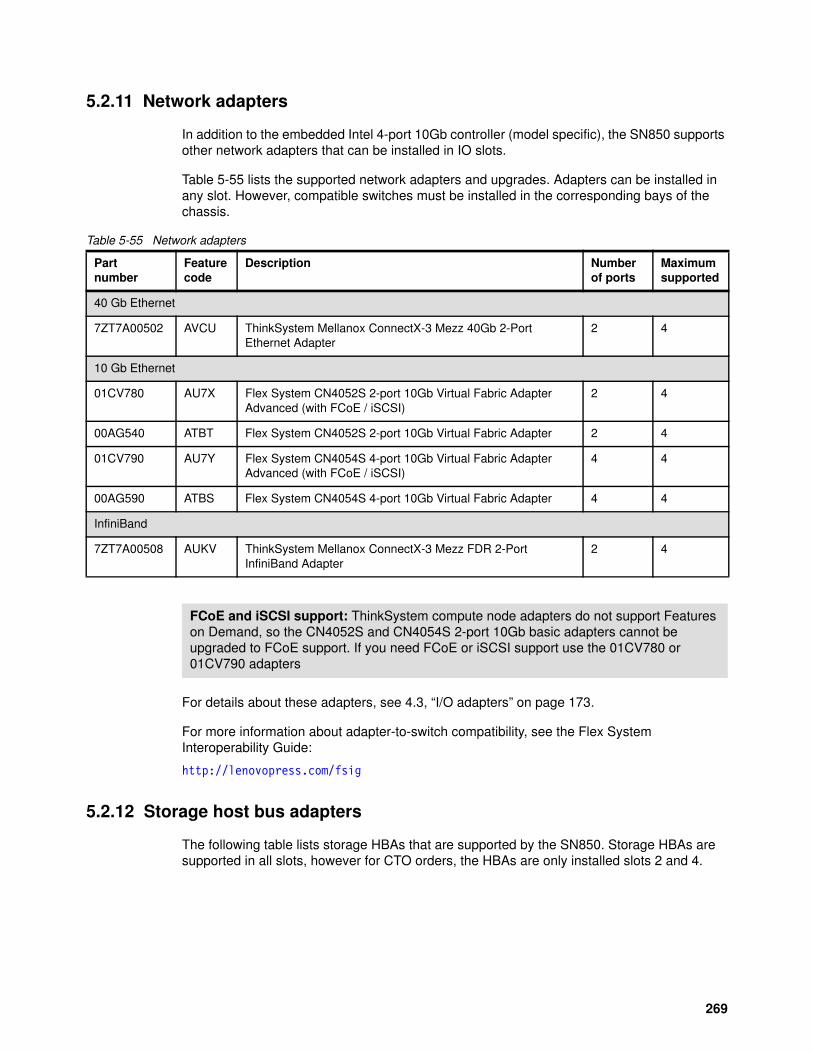
5.2.11 Network adapters
In addition to the embedded Intel 4-port 10Gb controller (model specific), the SN850 supports other network adapters that can be installed in IO slots.
Table 5-55 lists the supported network adapters and upgrades. Adapters can be installed in any slot. However, compatible switches must be installed in the corresponding bays of the chassis.
Table 5-55 Network adapters
For details about these adapters, see 4.3, “I/O adapters” on page 173.
For more information about adapter-to-switch compatibility, see the Flex System Interoperability Guide:
http://lenovopress.com/fsig
5.2.12 Storage host bus adapters
The following table lists storage HBAs that are supported by the SN850. Storage HBAs are supported in all slots, however for CTO orders, the HBAs are only installed slots 2 and 4.
Partnumber
Featurecode
Description Numberof ports
Maximumsupported
40 Gb Ethernet
7ZT7A00502 AVCU ThinkSystem Mellanox ConnectX-3 Mezz 40Gb 2-Port Ethernet Adapter
2 4
10 Gb Ethernet
01CV780 AU7X Flex System CN4052S 2-port 10Gb Virtual Fabric Adapter Advanced (with FCoE / iSCSI)
2 4
00AG540 ATBT Flex System CN4052S 2-port 10Gb Virtual Fabric Adapter 2 4
01CV790 AU7Y Flex System CN4054S 4-port 10Gb Virtual Fabric Adapter Advanced (with FCoE / iSCSI)
4 4
00AG590 ATBS Flex System CN4054S 4-port 10Gb Virtual Fabric Adapter 4 4
InfiniBand
7ZT7A00508 AUKV ThinkSystem Mellanox ConnectX-3 Mezz FDR 2-Port InfiniBand Adapter
2 4
FCoE and iSCSI support: ThinkSystem compute node adapters do not support Features on Demand, so the CN4052S and CN4054S 2-port 10Gb basic adapters cannot be upgraded to FCoE support. If you need FCoE or iSCSI support use the 01CV780 or 01CV790 adapters
269
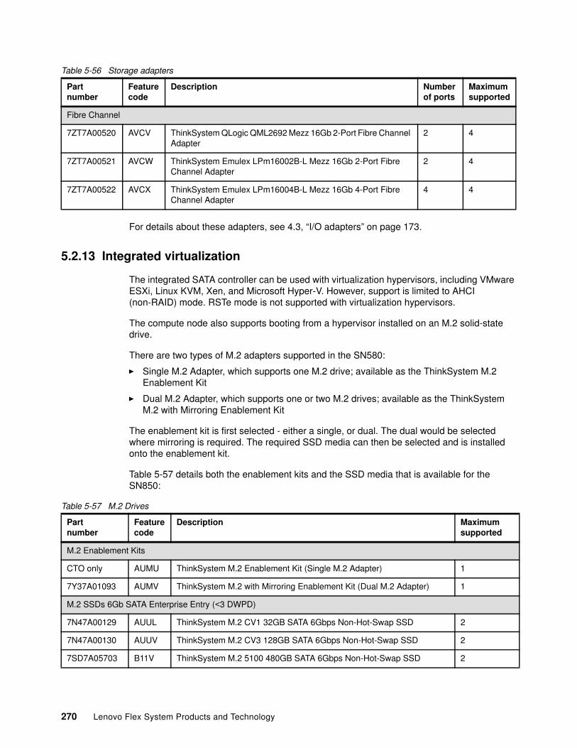
Table 5-56 Storage adapters
For details about these adapters, see 4.3, “I/O adapters” on page 173.
5.2.13 Integrated virtualization
The integrated SATA controller can be used with virtualization hypervisors, including VMware ESXi, Linux KVM, Xen, and Microsoft Hyper-V. However, support is limited to AHCI (non-RAID) mode. RSTe mode is not supported with virtualization hypervisors.
The compute node also supports booting from a hypervisor installed on an M.2 solid-state drive.
There are two types of M.2 adapters supported in the SN580:
� Single M.2 Adapter, which supports one M.2 drive; available as the ThinkSystem M.2 Enablement Kit
� Dual M.2 Adapter, which supports one or two M.2 drives; available as the ThinkSystem M.2 with Mirroring Enablement Kit
The enablement kit is first selected - either a single, or dual. The dual would be selected where mirroring is required. The required SSD media can then be selected and is installed onto the enablement kit.
Table 5-57 details both the enablement kits and the SSD media that is available for the SN850:
Table 5-57 M.2 Drives
Partnumber
Featurecode
Description Numberof ports
Maximumsupported
Fibre Channel
7ZT7A00520 AVCV ThinkSystem QLogic QML2692 Mezz 16Gb 2-Port Fibre Channel Adapter
2 4
7ZT7A00521 AVCW ThinkSystem Emulex LPm16002B-L Mezz 16Gb 2-Port Fibre Channel Adapter
2 4
7ZT7A00522 AVCX ThinkSystem Emulex LPm16004B-L Mezz 16Gb 4-Port Fibre Channel Adapter
4 4
Partnumber
Featurecode
Description Maximumsupported
M.2 Enablement Kits
CTO only AUMU ThinkSystem M.2 Enablement Kit (Single M.2 Adapter) 1
7Y37A01093 AUMV ThinkSystem M.2 with Mirroring Enablement Kit (Dual M.2 Adapter) 1
M.2 SSDs 6Gb SATA Enterprise Entry (<3 DWPD)
7N47A00129 AUUL ThinkSystem M.2 CV1 32GB SATA 6Gbps Non-Hot-Swap SSD 2
7N47A00130 AUUV ThinkSystem M.2 CV3 128GB SATA 6Gbps Non-Hot-Swap SSD 2
7SD7A05703 B11V ThinkSystem M.2 5100 480GB SATA 6Gbps Non-Hot-Swap SSD 2
270 Lenovo Flex System Products and Technology
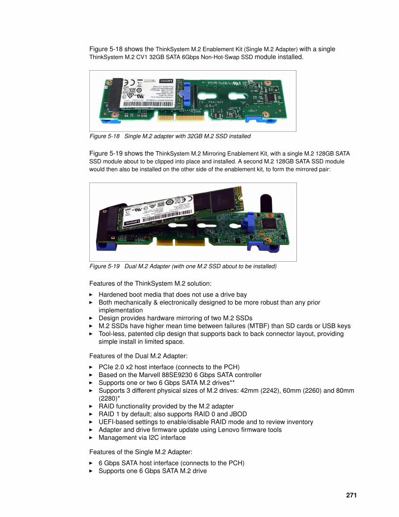
Figure 5-18 shows the ThinkSystem M.2 Enablement Kit (Single M.2 Adapter) with a single ThinkSystem M.2 CV1 32GB SATA 6Gbps Non-Hot-Swap SSD module installed.
Figure 5-18 Single M.2 adapter with 32GB M.2 SSD installed
Figure 5-19 shows the ThinkSystem M.2 Mirroring Enablement Kit, with a single M.2 128GB SATA SSD module about to be clipped into place and installed. A second M.2 128GB SATA SSD module would then also be installed on the other side of the enablement kit, to form the mirrored pair:
Figure 5-19 Dual M.2 Adapter (with one M.2 SSD about to be installed)
Features of the ThinkSystem M.2 solution:
� Hardened boot media that does not use a drive bay� Both mechanically & electronically designed to be more robust than any prior
implementation� Design provides hardware mirroring of two M.2 SSDs� M.2 SSDs have higher mean time between failures (MTBF) than SD cards or USB keys� Tool-less, patented clip design that supports back to back connector layout, providing
simple install in limited space.
Features of the Dual M.2 Adapter:
� PCIe 2.0 x2 host interface (connects to the PCH)� Based on the Marvell 88SE9230 6 Gbps SATA controller� Supports one or two 6 Gbps SATA M.2 drives**� Supports 3 different physical sizes of M.2 drives: 42mm (2242), 60mm (2260) and 80mm
(2280)*� RAID functionality provided by the M.2 adapter� RAID 1 by default; also supports RAID 0 and JBOD� UEFI-based settings to enable/disable RAID mode and to review inventory� Adapter and drive firmware update using Lenovo firmware tools� Management via I2C interface
Features of the Single M.2 Adapter:
� 6 Gbps SATA host interface (connects to the PCH)� Supports one 6 Gbps SATA M.2 drive
271
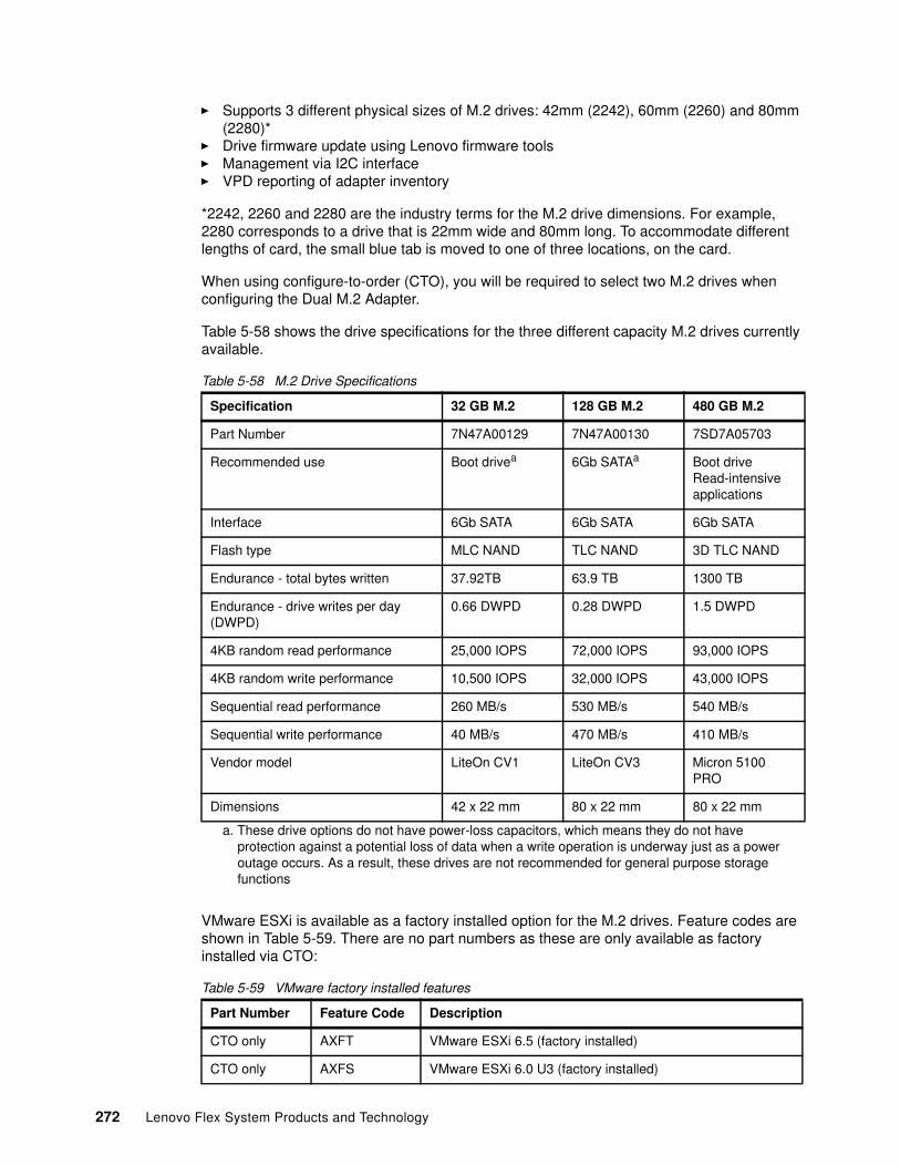
� Supports 3 different physical sizes of M.2 drives: 42mm (2242), 60mm (2260) and 80mm (2280)*
� Drive firmware update using Lenovo firmware tools� Management via I2C interface� VPD reporting of adapter inventory
*2242, 2260 and 2280 are the industry terms for the M.2 drive dimensions. For example, 2280 corresponds to a drive that is 22mm wide and 80mm long. To accommodate different lengths of card, the small blue tab is moved to one of three locations, on the card.
When using configure-to-order (CTO), you will be required to select two M.2 drives when configuring the Dual M.2 Adapter.
Table 5-58 shows the drive specifications for the three different capacity M.2 drives currently available.
Table 5-58 M.2 Drive Specifications
VMware ESXi is available as a factory installed option for the M.2 drives. Feature codes are shown in Table 5-59. There are no part numbers as these are only available as factory installed via CTO:
Table 5-59 VMware factory installed features
Specification 32 GB M.2 128 GB M.2 480 GB M.2
Part Number 7N47A00129 7N47A00130 7SD7A05703
Recommended use Boot drivea
a. These drive options do not have power-loss capacitors, which means they do not have protection against a potential loss of data when a write operation is underway just as a power outage occurs. As a result, these drives are not recommended for general purpose storage functions
6Gb SATAa Boot driveRead-intensive applications
Interface 6Gb SATA 6Gb SATA 6Gb SATA
Flash type MLC NAND TLC NAND 3D TLC NAND
Endurance - total bytes written 37.92TB 63.9 TB 1300 TB
Endurance - drive writes per day (DWPD)
0.66 DWPD 0.28 DWPD 1.5 DWPD
4KB random read performance 25,000 IOPS 72,000 IOPS 93,000 IOPS
4KB random write performance 10,500 IOPS 32,000 IOPS 43,000 IOPS
Sequential read performance 260 MB/s 530 MB/s 540 MB/s
Sequential write performance 40 MB/s 470 MB/s 410 MB/s
Vendor model LiteOn CV1 LiteOn CV3 Micron 5100 PRO
Dimensions 42 x 22 mm 80 x 22 mm 80 x 22 mm
Part Number Feature Code Description
CTO only AXFT VMware ESXi 6.5 (factory installed)
CTO only AXFS VMware ESXi 6.0 U3 (factory installed)
272 Lenovo Flex System Products and Technology
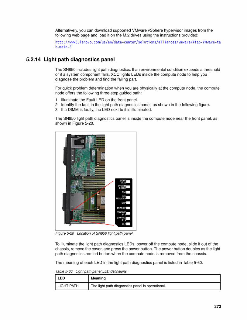
Alternatively, you can download supported VMware vSphere hypervisor images from the following web page and load it on the M.2 drives using the instructions provided:
http://www3.lenovo.com/us/en/data-center/solutions/alliances/vmware/#tab-VMware-tab-main-2
5.2.14 Light path diagnostics panel
The SN850 includes light path diagnostics. If an environmental condition exceeds a threshold or if a system component fails, XCC lights LEDs inside the compute node to help you diagnose the problem and find the failing part.
For quick problem determination when you are physically at the compute node, the compute node offers the following three-step guided path:
1. Illuminate the Fault LED on the front panel. 2. Identify the fault in the light path diagnostics panel, as shown in the following figure.3. If a DIMM is faulty, the LED next to it is illuminated.
The SN850 light path diagnostics panel is inside the compute node near the front panel, as shown in Figure 5-20.
Figure 5-20 Location of SN850 light path panel
To illuminate the light path diagnostics LEDs, power off the compute node, slide it out of the chassis, remove the cover, and press the power button. The power button doubles as the light path diagnostics remind button when the compute node is removed from the chassis.
The meaning of each LED in the light path diagnostics panel is listed in Table 5-60.
Table 5-60 Light path panel LED definitions
LED Meaning
LIGHT PATH The light path diagnostics panel is operational.
273
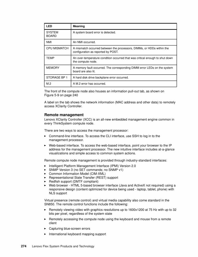
The front of the compute node also houses an information pull-out tab, as shown on Figure 5-9 on page 240
A label on the tab shows the network information (MAC address and other data) to remotely access XClarity Controller.
Remote managementLenovo XClarity Controller (XCC) is an all-new embedded management engine common in every ThinkSystem compute node.
There are two ways to access the management processor:
� Command-line interface. To access the CLI interface, use SSH to log in to the management processor.
� Web-based interface. To access the web-based interface, point your browser to the IP address for the management processor. The new intuitive interface includes at-a-glance visualizations and simple access to common system actions.
Remote compute node management is provided through industry-standard interfaces:
� Intelligent Platform Management Interface (IPMI) Version 2.0� SNMP Version 3 (no SET commands; no SNMP v1)� Common Information Model (CIM-XML)� Representational State Transfer (REST) support� Redfish support (DMTF compliant)� Web browser - HTML 5-based browser interface (Java and ActiveX not required) using a
responsive design (content optimized for device being used - laptop, tablet, phone) with NLS support
Virtual presence (remote control) and virtual media capability also come standard in the SN850. The remote control functions include the following:
� Remotely viewing video with graphics resolutions up to 1600x1200 at 75 Hz with up to 32 bits per pixel, regardless of the system state
� Remotely accessing the compute node using the keyboard and mouse from a remote client
� Capturing blue-screen errors
� International keyboard mapping support
SYSTEM BOARD
A system board error is detected.
NMI An NMI occurred.
CPU MISMATCH A mismatch occurred between the processors, DIMMs, or HDDs within the configuration as reported by POST.
TEMP An over-temperature condition occurred that was critical enough to shut down the compute node.
MEMORY A memory fault occurred. The corresponding DIMM error LEDs on the system board are also lit.
STORAGE BP 1 A hard disk drive backplane error occurred.
M.2 A M.2 error has occurred.
LED Meaning
274 Lenovo Flex System Products and Technology
� LDAP-based authentication
� Remote mounting of ISO and diskette IMG image files as virtual drives that are available for use by the compute node
� Boot Capture
� Virtual console collaboration - Ability for up to 6 remote users to be log into the remote session simultaneously
� Power capping
5.2.15 Operating systems support
The server supports the following operating systems:
� Microsoft Windows Server 2012 R2� Microsoft Windows Server 2016� Microsoft Windows Server, version 1709� Red Hat Enterprise Linux 6.9 x64� Red Hat Enterprise Linux 7.3� Red Hat Enterprise Linux 7.4� SUSE Linux Enterprise Server 11 Xen x64 SP4� SUSE Linux Enterprise Server 11 x64 SP4� SUSE Linux Enterprise Server 12 SP2� SUSE Linux Enterprise Server 12 SP3� SUSE Linux Enterprise Server 12 Xen SP2� SUSE Linux Enterprise Server 12 Xen SP3� VMware ESXi 6.0 U3� VMware ESXi 6.5� VMware ESXi 6.5 U1
For a complete list of supported, certified and tested operating systems, plus additional details and links to relevant web sites, see the Operating System Interoperability Guide:
https://lenovopress.com/osig#servers=sn850-7x15
275
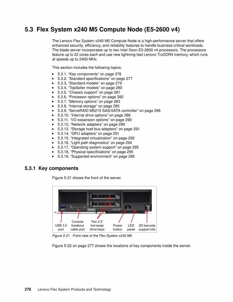
5.3 Flex System x240 M5 Compute Node (E5-2600 v4)
The Lenovo Flex System x240 M5 Compute Node is a high-performance server that offers enhanced security, efficiency, and reliability features to handle business-critical workloads. The blade server incorporates up to two Intel Xeon E5-2600 v4 processors. The processors feature up to 22 cores each and use new lightning-fast Lenovo TruDDR4 memory, which runs at speeds up to 2400 MHz.
This section includes the following topics:
� 5.3.1, “Key components” on page 276� 5.3.2, “Standard specifications” on page 277� 5.3.3, “Standard models” on page 279� 5.3.4, “TopSeller models” on page 280� 5.3.5, “Chassis support” on page 281� 5.3.6, “Processor options” on page 282� 5.3.7, “Memory options” on page 283� 5.3.8, “Internal storage” on page 285� 5.3.9, “ServeRAID M5215 SAS/SATA controller” on page 286� 5.3.10, “Internal drive options” on page 288� 5.3.11, “I/O expansion options” on page 290� 5.3.12, “Network adapters” on page 290� 5.3.13, “Storage host bus adapters” on page 291� 5.3.14, “GPU adapters” on page 291� 5.3.15, “Integrated virtualization” on page 292� 5.3.16, “Light path diagnostics” on page 294� 5.3.17, “Operating system support” on page 295� 5.3.18, “Physical specifications” on page 295� 5.3.19, “Supported environment” on page 295
5.3.1 Key components
Figure 5-21 shows the front of the server.
Figure 5-21 Front view of the Flex System x240 M5
Figure 5-22 on page 277 shows the locations of key components inside the server.
USB 3.0port
Consolebreakoutcable port
Two 2.5” hot-swapdrive bays
LEDpanel
Powerbutton
2D barcodesupport info
276 Lenovo Flex System Products and Technology
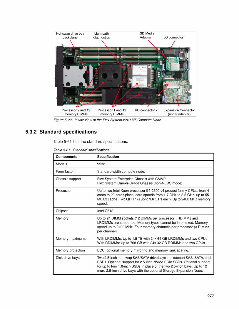
Figure 5-22 Inside view of the Flex System x240 M5 Compute Node
5.3.2 Standard specifications
Table 5-61 lists the standard specifications.
Table 5-61 Standard specifications
Hot-swap drive bay backplane
Processor 2 and 12 memory DIMMs
I/O connector 2
Light path diagnostics
Processor 1 and 12 memory DIMMs
Expansion Connector(under adapter)
I/O connector 1SD Media Adapter
Components Specification
Models 9532
Form factor Standard-width compute node.
Chassis support Flex System Enterprise Chassis with CMM2.Flex System Carrier-Grade Chassis (non-NEBS mode)
Processor Up to two Intel Xeon processor E5-2600 v4 product family CPUs: from 4 cores to 22 cores piece; core speeds from 1.7 GHz to 3.5 GHz; up to 55 MB L3 cache. Two QPI links up to 9.6 GT/s each. Up to 2400 MHz memory speed.
Chipset Intel C612
Memory Up to 24 DIMM sockets (12 DIMMs per processor). RDIMMs and LRDIMMs are supported. Memory types cannot be intermixed. Memory speed up to 2400 MHz. Four memory channels per processor (3 DIMMs per channel).
Memory maximums With LRDIMMs: Up to 1.5 TB with 24x 64 GB LRDIMMs and two CPUsWith RDIMMs: Up to 768 GB with 24x 32 GB RDIMMs and two CPUs
Memory protection ECC, optional memory mirroring and memory rank sparing.
Disk drive bays Two 2.5-inch hot-swap SAS/SATA drive bays that support SAS, SATA, and SSDs. Optional support for 2.5-inch NVMe PCIe SSDs. Optional support for up to four 1.8-inch SSDs in place of the two 2.5-inch bays. Up to 12 more 2.5-inch drive bays with the optional Storage Expansion Node.
277
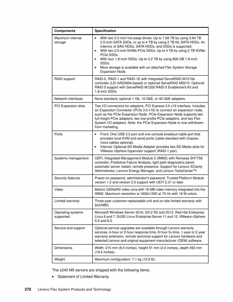
The x240 M5 servers are shipped with the following items:
� Statement of Limited Warranty
Maximum internal storage
� With two 2.5-inch hot-swap drives: Up to 7.68 TB by using 3.84 TB 2.5-inch SATA SSDs, or up to 4 TB by using 2 TB NL SATA HDDs. An intermix of SAS HDDs, SATA HDDs, and SSDs is supported.
� With two 2.5-inch NVMe PCIe SSDs: Up to 4 TB by using 2 TB NVMe PCIe SSDs.
� With four 1.8-inch SSDs: Up to 3.2 TB by using 800 GB 1.8-inch SSDs.
� More storage is available with an attached Flex System Storage Expansion Node.
RAID support RAID-0, RAID-1 and RAID-1E with integrated ServeRAID M1210e controller (LSI SAS3004-based) or optional ServeRAID M5215. Optional RAID-5 support with ServeRAID M1200 RAID-5 Enablement Kit and 1.8-inch SSDs
Network interfaces None standard; optional 1 Gb, 10 GbE, or 40 GbE adapters.
PCI Expansion slots Two I/O connectors for adapters. PCI Express 3.0 x16 interface. Includes an Expansion Connector (PCIe 3.0 x16) to connect an expansion node, such as the PCIe Expansion Node. PCIe Expansion Node supports two full-height PCIe adapters, two low-profile PCIe adapters, and two Flex System I/O adapters. Note: the PCIe Expansion Node is now withdrawn from marketing.
Ports � Front: One USB 3.0 port and one console breakout cable port that provides local KVM and serial ports (cable standard with chassis; more cables optional).
� Internal: Optional SD Media Adapter provides two SD Media slots for VMware vSphere hypervisor support (RAID-1 pair).
Systems management UEFI, Integrated Management Module 2 (IMM2) with Renesas SH7758 controller, Predictive Failure Analysis, light path diagnostics panel, automatic server restart, remote presence. Support for Lenovo XClarity Administrator, Lenovo Energy Manager, and Lenovo ToolsCenter™.
Security features Power-on password, administrator's password, Trusted Platform Module version 1.2 and version 2.0 support with UEFI 2.21 or later.
Video Matrox G200eR2 video core with 16 MB video memory integrated into the IMM2. Maximum resolution is 1600x1200 at 75 Hz with 16 M colors.
Limited warranty Three-year customer-replaceable unit and on-site limited warranty with 9x5/NBD.
Operating systems supported
Microsoft Windows Server 2016, 2012 R2 and 2012, Red Hat Enterprise Linux 6 and 7, SUSE Linux Enterprise Server 11 and 12, VMware vSphere 5.5 and 6.0.
Service and support Optional service upgrades are available through Lenovo warranty services: 4-hour or 2-hour response time, 8-hour fix time, 1-year or 2-year warranty extension, remote technical support for Lenovo hardware and selected Lenovo and original equipment manufacturer (OEM) software.
Dimensions Width: 215 mm (8.5 inches), height 51 mm (2.0 inches), depth 493 mm (19.4 inches).
Weight Maximum configuration: 7.1 kg (15.6 lb).
Components Specification
278 Lenovo Flex System Products and Technology
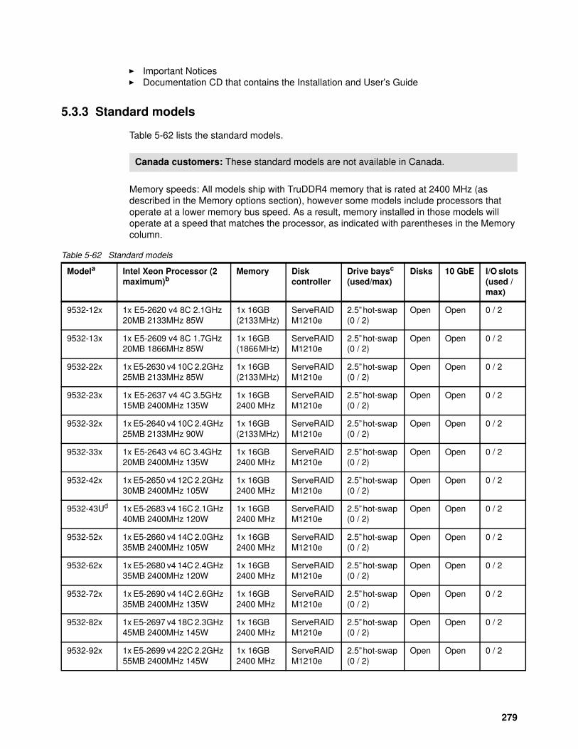
� Important Notices� Documentation CD that contains the Installation and User's Guide
5.3.3 Standard models
Table 5-62 lists the standard models.
Memory speeds: All models ship with TruDDR4 memory that is rated at 2400 MHz (as described in the Memory options section), however some models include processors that operate at a lower memory bus speed. As a result, memory installed in those models will operate at a speed that matches the processor, as indicated with parentheses in the Memory column.
Table 5-62 Standard models
Canada customers: These standard models are not available in Canada.
Modela Intel Xeon Processor (2 maximum)b
Memory Disk controller
Drive baysc (used/max)
Disks 10 GbE I/O slots (used / max)
9532-12x 1x E5-2620 v4 8C 2.1GHz 20MB 2133MHz 85W
1x 16GB (2133 MHz)
ServeRAID M1210e
2.5” hot-swap (0 / 2)
Open Open 0 / 2
9532-13x 1x E5-2609 v4 8C 1.7GHz 20MB 1866MHz 85W
1x 16GB (1866 MHz)
ServeRAID M1210e
2.5” hot-swap (0 / 2)
Open Open 0 / 2
9532-22x 1x E5-2630 v4 10C 2.2GHz 25MB 2133MHz 85W
1x 16GB (2133 MHz)
ServeRAID M1210e
2.5” hot-swap (0 / 2)
Open Open 0 / 2
9532-23x 1x E5-2637 v4 4C 3.5GHz 15MB 2400MHz 135W
1x 16GB 2400 MHz
ServeRAID M1210e
2.5” hot-swap (0 / 2)
Open Open 0 / 2
9532-32x 1x E5-2640 v4 10C 2.4GHz 25MB 2133MHz 90W
1x 16GB (2133 MHz)
ServeRAID M1210e
2.5” hot-swap (0 / 2)
Open Open 0 / 2
9532-33x 1x E5-2643 v4 6C 3.4GHz 20MB 2400MHz 135W
1x 16GB 2400 MHz
ServeRAID M1210e
2.5” hot-swap (0 / 2)
Open Open 0 / 2
9532-42x 1x E5-2650 v4 12C 2.2GHz 30MB 2400MHz 105W
1x 16GB 2400 MHz
ServeRAID M1210e
2.5” hot-swap (0 / 2)
Open Open 0 / 2
9532-43Ud 1x E5-2683 v4 16C 2.1GHz 40MB 2400MHz 120W
1x 16GB 2400 MHz
ServeRAID M1210e
2.5” hot-swap (0 / 2)
Open Open 0 / 2
9532-52x 1x E5-2660 v4 14C 2.0GHz 35MB 2400MHz 105W
1x 16GB 2400 MHz
ServeRAID M1210e
2.5” hot-swap (0 / 2)
Open Open 0 / 2
9532-62x 1x E5-2680 v4 14C 2.4GHz 35MB 2400MHz 120W
1x 16GB 2400 MHz
ServeRAID M1210e
2.5” hot-swap (0 / 2)
Open Open 0 / 2
9532-72x 1x E5-2690 v4 14C 2.6GHz 35MB 2400MHz 135W
1x 16GB 2400 MHz
ServeRAID M1210e
2.5” hot-swap (0 / 2)
Open Open 0 / 2
9532-82x 1x E5-2697 v4 18C 2.3GHz 45MB 2400MHz 145W
1x 16GB 2400 MHz
ServeRAID M1210e
2.5” hot-swap (0 / 2)
Open Open 0 / 2
9532-92x 1x E5-2699 v4 22C 2.2GHz 55MB 2400MHz 145W
1x 16GB 2400 MHz
ServeRAID M1210e
2.5” hot-swap (0 / 2)
Open Open 0 / 2
279
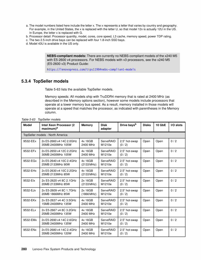
5.3.4 TopSeller models
Table 5-63 lists the available TopSeller models.
Memory speeds: All models ship with TruDDR4 memory that is rated at 2400 MHz (as described in the Memory options section), however some models include processors that operate at a lower memory bus speed. As a result, memory installed in those models will operate at a speed that matches the processor, as indicated with parentheses in the Memory column.
Table 5-63 TopSeller models
a. The model numbers listed here include the letter x. The x represents a letter that varies by country and geography. For example, in the United States, the x is replaced with the letter U, so that model 12x is actually 12U in the US. In Europe, the letter x is replaced with G.
b. Processor detail: Processor quantity, model, cores, core speed, L3 cache, memory speed, power TDP rating.c. The two 2.5-inch drive bays can be replaced with four 1.8-inch SSD bays.d. Model 43U is available in the US only.
NEBS-compliant models: There are currently no NEBS-compliant models of the x240 M5 with E5-2600 v4 processors. For NEBS models with v3 processors, see the x240 M5 (E5-2600 v3) Product Guide:
https://lenovopress.com/tips1199#nebs-compliant-models
Model Intel Xeon Processor (2 maximum)a
Memory Disk adapter
Drive baysb Disks 10 GbE I/O slots
TopSeller models - North America
9532-EEx 2x E5-2660 v4 14C 2.0GHz 35MB 2400MHz 105W
4x 16GB 2400 MHz
ServeRAID M1210e
2.5” hot-swap (0 / 2)
Open Open 0 / 2
9532-EFx 2x E5-2650 v4 12C 2.2GHz 30MB 2400MHz 105W
4x 16GB 2400 MHz
ServeRAID M1210e
2.5” hot-swap (0 / 2)
Open Open 0 / 2
9532-EGx 2x E5-2640 v4 10C 2.4GHz 25MB 2133MHz 90W
4x 16GB (2133 MHz)
ServeRAID M1210e
2.5” hot-swap (0 / 2)
Open Open 0 / 2
9532-EHx 2x E5-2630 v4 10C 2.2GHz 25MB 2133MHz 85W
4x 16GB (2133 MHz)
ServeRAID M1210e
2.5” hot-swap (0 / 2)
Open Open 0 / 2
9532-EIx 2x E5-2620 v4 8C 2.1GHz 20MB 2133MHz 85W
2x 16GB (2133 MHz)
ServeRAID M1210e
2.5” hot-swap (0 / 2)
Open Open 0 / 2
9532-EJx 2x E5-2609 v4 8C 1.7GHz 20MB 1866MHz 85W
2x 16GB (1866 MHz)
ServeRAID M1210e
2.5” hot-swap (0 / 2)
Open Open 0 / 2
9532-EKx 2x E5-2637 v4 4C 3.5GHz 15MB 2400MHz 135W
4x 16GB 2400 MHz
ServeRAID M1210e
2.5” hot-swap (0 / 2)
Open Open 0 / 2
9532-ELx 2x E5-2667 v4 8C 3.2GHz 25MB 2400MHz 135W
4x 16GB 2400 MHz
ServeRAID M1210e
2.5” hot-swap (0 / 2)
Open Open 0 / 2
9532-EMx 2x E5-2690 v4 14C 2.6GHz 35MB 2400MHz 135W
4x 16GB 2400 MHz
ServeRAID M1210e
2.5” hot-swap (0 / 2)
Open Open 0 / 2
9532-ENx 2x E5-2680 v4 14C 2.4GHz 35MB 2400MHz 120W
4x 16GB 2400 MHz
ServeRAID M1210e
2.5” hot-swap (0 / 2)
Open Open 0 / 2
280 Lenovo Flex System Products and Technology
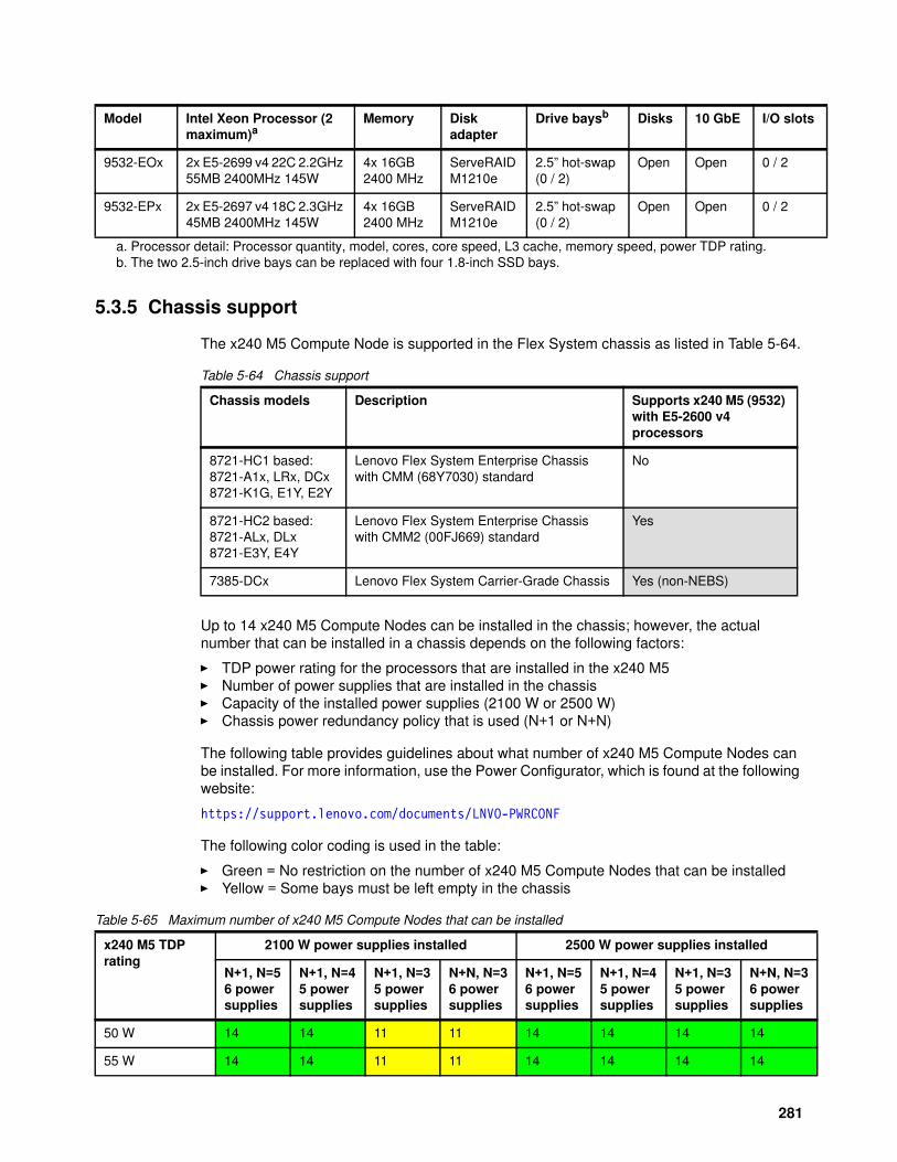
5.3.5 Chassis support
The x240 M5 Compute Node is supported in the Flex System chassis as listed in Table 5-64.
Table 5-64 Chassis support
Up to 14 x240 M5 Compute Nodes can be installed in the chassis; however, the actual number that can be installed in a chassis depends on the following factors:
� TDP power rating for the processors that are installed in the x240 M5� Number of power supplies that are installed in the chassis� Capacity of the installed power supplies (2100 W or 2500 W)� Chassis power redundancy policy that is used (N+1 or N+N)
The following table provides guidelines about what number of x240 M5 Compute Nodes can be installed. For more information, use the Power Configurator, which is found at the following website:
https://support.lenovo.com/documents/LNVO-PWRCONF
The following color coding is used in the table:
� Green = No restriction on the number of x240 M5 Compute Nodes that can be installed� Yellow = Some bays must be left empty in the chassis
Table 5-65 Maximum number of x240 M5 Compute Nodes that can be installed
9532-EOx 2x E5-2699 v4 22C 2.2GHz 55MB 2400MHz 145W
4x 16GB 2400 MHz
ServeRAID M1210e
2.5” hot-swap (0 / 2)
Open Open 0 / 2
9532-EPx 2x E5-2697 v4 18C 2.3GHz 45MB 2400MHz 145W
4x 16GB 2400 MHz
ServeRAID M1210e
2.5” hot-swap (0 / 2)
Open Open 0 / 2
a. Processor detail: Processor quantity, model, cores, core speed, L3 cache, memory speed, power TDP rating.b. The two 2.5-inch drive bays can be replaced with four 1.8-inch SSD bays.
Model Intel Xeon Processor (2 maximum)a
Memory Disk adapter
Drive baysb Disks 10 GbE I/O slots
Chassis models Description Supports x240 M5 (9532) with E5-2600 v4 processors
8721-HC1 based:8721-A1x, LRx, DCx8721-K1G, E1Y, E2Y
Lenovo Flex System Enterprise Chassiswith CMM (68Y7030) standard
No
8721-HC2 based:8721-ALx, DLx8721-E3Y, E4Y
Lenovo Flex System Enterprise Chassiswith CMM2 (00FJ669) standard
Yes
7385-DCx Lenovo Flex System Carrier-Grade Chassis Yes (non-NEBS)
x240 M5 TDP rating
2100 W power supplies installed 2500 W power supplies installed
N+1, N=56 powersupplies
N+1, N=45 powersupplies
N+1, N=35 powersupplies
N+N, N=36 powersupplies
N+1, N=56 powersupplies
N+1, N=45 powersupplies
N+1, N=35 powersupplies
N+N, N=36 powersupplies
50 W 14 14 11 11 14 14 14 14
55 W 14 14 11 11 14 14 14 14
281
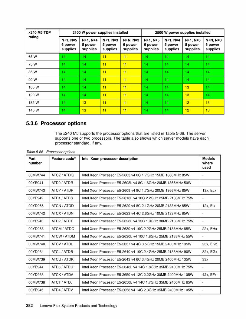
5.3.6 Processor options
The x240 M5 supports the processor options that are listed in Table 5-66. The server supports one or two processors. The table also shows which server models have each processor standard, if any.
Table 5-66 Processor options
65 W 14 14 11 11 14 14 14 14
75 W 14 14 11 11 14 14 14 14
85 W 14 14 11 11 14 14 14 14
90 W 14 14 11 11 14 14 14 14
105 W 14 14 11 11 14 14 13 14
120 W 14 14 11 11 14 14 13 14
135 W 14 13 11 11 14 14 12 13
145 W 14 13 11 11 14 14 12 13
x240 M5 TDP rating
2100 W power supplies installed 2500 W power supplies installed
N+1, N=56 powersupplies
N+1, N=45 powersupplies
N+1, N=35 powersupplies
N+N, N=36 powersupplies
N+1, N=56 powersupplies
N+1, N=45 powersupplies
N+1, N=35 powersupplies
N+N, N=36 powersupplies
Partnumber
Feature codea Intel Xeon processor description Modelswhereused
00MW744 ATCZ / ATDQ Intel Xeon Processor E5-2603 v4 6C 1.7GHz 15MB 1866MHz 85W -
00YE941 ATD0 / ATDR Intel Xeon Processor E5-2608L v4 8C 1.6GHz 20MB 1866MHz 50W -
00MW743 ATCY / ATDP Intel Xeon Processor E5-2609 v4 8C 1.7GHz 20MB 1866MHz 85W 13x, EJx
00YE942 ATD1 / ATDS Intel Xeon Processor E5-2618L v4 10C 2.2GHz 25MB 2133MHz 75W -
00YD966 ATCN / ATDD Intel Xeon Processor E5-2620 v4 8C 2.1GHz 20MB 2133MHz 85W 12x, EIx
00MW742 ATCX / ATDN Intel Xeon Processor E5-2623 v4 4C 2.6GHz 10MB 2133MHz 85W -
00YE943 ATD2 / ATDT Intel Xeon Processor E5-2628L v4 12C 1.9GHz 30MB 2133MHz 75W -
00YD965 ATCM / ATDC Intel Xeon Processor E5-2630 v4 10C 2.2GHz 25MB 2133MHz 85W 22x, EHx
00MW741 ATCW / ATDM Intel Xeon Processor E5-2630L v4 10C 1.8GHz 25MB 2133MHz 55W -
00MW740 ATCV / ATDL Intel Xeon Processor E5-2637 v4 4C 3.5GHz 15MB 2400MHz 135W 23x, EKx
00YD964 ATCL / ATDB Intel Xeon Processor E5-2640 v4 10C 2.4GHz 25MB 2133MHz 90W 32x, EGx
00MW739 ATCU / ATDK Intel Xeon Processor E5-2643 v4 6C 3.4GHz 20MB 2400MHz 135W 33x
00YE944 ATD3 / ATDU Intel Xeon Processor E5-2648L v4 14C 1.8GHz 35MB 2400MHz 75W -
00YD963 ATCK / ATDA Intel Xeon Processor E5-2650 v4 12C 2.2GHz 30MB 2400MHz 105W 42x, EFx
00MW738 ATCT / ATDJ Intel Xeon Processor E5-2650L v4 14C 1.7GHz 35MB 2400MHz 65W -
00YE945 ATD4 / ATDV Intel Xeon Processor E5-2658 v4 14C 2.3GHz 35MB 2400MHz 105W -
282 Lenovo Flex System Products and Technology
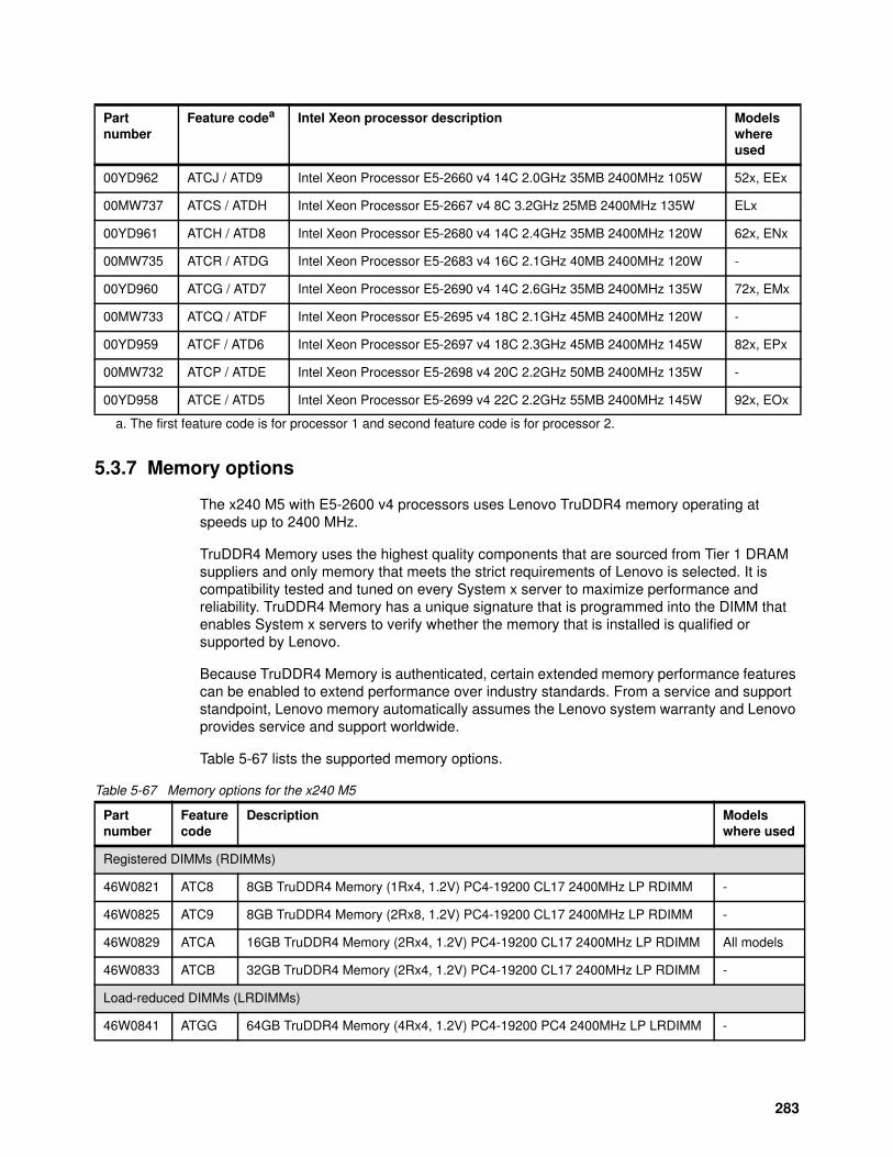
5.3.7 Memory options
The x240 M5 with E5-2600 v4 processors uses Lenovo TruDDR4 memory operating at speeds up to 2400 MHz.
TruDDR4 Memory uses the highest quality components that are sourced from Tier 1 DRAM suppliers and only memory that meets the strict requirements of Lenovo is selected. It is compatibility tested and tuned on every System x server to maximize performance and reliability. TruDDR4 Memory has a unique signature that is programmed into the DIMM that enables System x servers to verify whether the memory that is installed is qualified or supported by Lenovo.
Because TruDDR4 Memory is authenticated, certain extended memory performance features can be enabled to extend performance over industry standards. From a service and support standpoint, Lenovo memory automatically assumes the Lenovo system warranty and Lenovo provides service and support worldwide.
Table 5-67 lists the supported memory options.
Table 5-67 Memory options for the x240 M5
00YD962 ATCJ / ATD9 Intel Xeon Processor E5-2660 v4 14C 2.0GHz 35MB 2400MHz 105W 52x, EEx
00MW737 ATCS / ATDH Intel Xeon Processor E5-2667 v4 8C 3.2GHz 25MB 2400MHz 135W ELx
00YD961 ATCH / ATD8 Intel Xeon Processor E5-2680 v4 14C 2.4GHz 35MB 2400MHz 120W 62x, ENx
00MW735 ATCR / ATDG Intel Xeon Processor E5-2683 v4 16C 2.1GHz 40MB 2400MHz 120W -
00YD960 ATCG / ATD7 Intel Xeon Processor E5-2690 v4 14C 2.6GHz 35MB 2400MHz 135W 72x, EMx
00MW733 ATCQ / ATDF Intel Xeon Processor E5-2695 v4 18C 2.1GHz 45MB 2400MHz 120W -
00YD959 ATCF / ATD6 Intel Xeon Processor E5-2697 v4 18C 2.3GHz 45MB 2400MHz 145W 82x, EPx
00MW732 ATCP / ATDE Intel Xeon Processor E5-2698 v4 20C 2.2GHz 50MB 2400MHz 135W -
00YD958 ATCE / ATD5 Intel Xeon Processor E5-2699 v4 22C 2.2GHz 55MB 2400MHz 145W 92x, EOx
a. The first feature code is for processor 1 and second feature code is for processor 2.
Partnumber
Feature codea Intel Xeon processor description Modelswhereused
Partnumber
Featurecode
Description Modelswhere used
Registered DIMMs (RDIMMs)
46W0821 ATC8 8GB TruDDR4 Memory (1Rx4, 1.2V) PC4-19200 CL17 2400MHz LP RDIMM -
46W0825 ATC9 8GB TruDDR4 Memory (2Rx8, 1.2V) PC4-19200 CL17 2400MHz LP RDIMM -
46W0829 ATCA 16GB TruDDR4 Memory (2Rx4, 1.2V) PC4-19200 CL17 2400MHz LP RDIMM All models
46W0833 ATCB 32GB TruDDR4 Memory (2Rx4, 1.2V) PC4-19200 CL17 2400MHz LP RDIMM -
Load-reduced DIMMs (LRDIMMs)
46W0841 ATGG 64GB TruDDR4 Memory (4Rx4, 1.2V) PC4-19200 PC4 2400MHz LP LRDIMM -
283
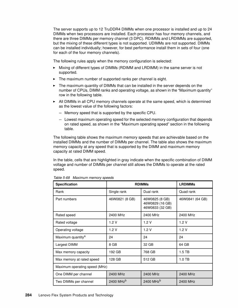
The server supports up to 12 TruDDR4 DIMMs when one processor is installed and up to 24 DIMMs when two processors are installed. Each processor has four memory channels, and there are three DIMMs per memory channel (3 DPC). RDIMMs and LRDIMMs are supported, but the mixing of these different types is not supported. UDIMMs are not supported. DIMMs can be installed individually; however, for best performance install them in sets of four (one for each of the four memory channels).
The following rules apply when the memory configuration is selected:
� Mixing of different types of DIMMs (RDIMM and LRDIMM) in the same server is not supported.
� The maximum number of supported ranks per channel is eight.
� The maximum quantity of DIMMs that can be installed in the server depends on the number of CPUs, DIMM ranks and operating voltage, as shown in the “Maximum quantity” row in the following table.
� All DIMMs in all CPU memory channels operate at the same speed, which is determined as the lowest value of the following factors:
– Memory speed that is supported by the specific CPU.
– Lowest maximum operating speed for the selected memory configuration that depends on rated speed, as shown in the “Maximum operating speed” section in the following table.
The following table shows the maximum memory speeds that are achievable based on the installed DIMMs and the number of DIMMs per channel. The table also shows the maximum memory capacity at any speed that is supported by the DIMM and maximum memory capacity at rated DIMM speed.
In the table, cells that are highlighted in gray indicate when the specific combination of DIMM voltage and number of DIMMs per channel still allows the DIMMs to operate at the rated speed.
Table 5-68 Maximum memory speeds
Specification RDIMMs LRDIMMs
Rank Single rank Dual rank Quad rank
Part numbers 46W0821 (8 GB) 46W0825 (8 GB)46W0829 (16 GB)46W0833 (32 GB)
46W0841 (64 GB)
Rated speed 2400 MHz 2400 MHz 2400 MHz
Rated voltage 1.2 V 1.2 V 1.2 V
Operating voltage 1.2 V 1.2 V 1.2 V
Maximum quantitya 24 24 24
Largest DIMM 8 GB 32 GB 64 GB
Max memory capacity 192 GB 768 GB 1.5 TB
Max memory at rated speed 128 GB 512 GB 1.0 TB
Maximum operating speed (MHz)
One DIMM per channel 2400 MHz 2400 MHz 2400 MHz
Two DIMMs per channel 2400 MHzb 2400 MHzb 2400 MHz
284 Lenovo Flex System Products and Technology
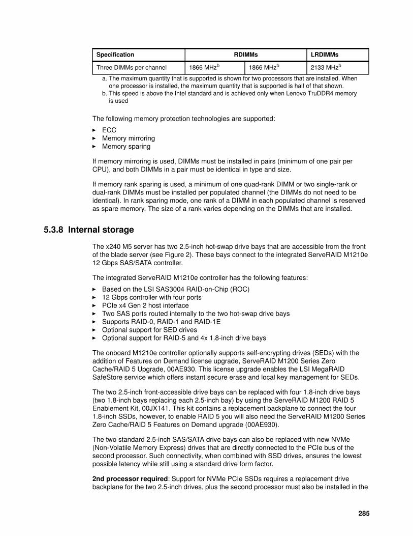
The following memory protection technologies are supported:
� ECC� Memory mirroring� Memory sparing
If memory mirroring is used, DIMMs must be installed in pairs (minimum of one pair per CPU), and both DIMMs in a pair must be identical in type and size.
If memory rank sparing is used, a minimum of one quad-rank DIMM or two single-rank or dual-rank DIMMs must be installed per populated channel (the DIMMs do not need to be identical). In rank sparing mode, one rank of a DIMM in each populated channel is reserved as spare memory. The size of a rank varies depending on the DIMMs that are installed.
5.3.8 Internal storage
The x240 M5 server has two 2.5-inch hot-swap drive bays that are accessible from the front of the blade server (see Figure 2). These bays connect to the integrated ServeRAID M1210e 12 Gbps SAS/SATA controller.
The integrated ServeRAID M1210e controller has the following features:
� Based on the LSI SAS3004 RAID-on-Chip (ROC)� 12 Gbps controller with four ports� PCIe x4 Gen 2 host interface� Two SAS ports routed internally to the two hot-swap drive bays� Supports RAID-0, RAID-1 and RAID-1E� Optional support for SED drives� Optional support for RAID-5 and 4x 1.8-inch drive bays
The onboard M1210e controller optionally supports self-encrypting drives (SEDs) with the addition of Features on Demand license upgrade, ServeRAID M1200 Series Zero Cache/RAID 5 Upgrade, 00AE930. This license upgrade enables the LSI MegaRAID SafeStore service which offers instant secure erase and local key management for SEDs.
The two 2.5-inch front-accessible drive bays can be replaced with four 1.8-inch drive bays (two 1.8-inch bays replacing each 2.5-inch bay) by using the ServeRAID M1200 RAID 5 Enablement Kit, 00JX141. This kit contains a replacement backplane to connect the four 1.8-inch SSDs, however, to enable RAID 5 you will also need the ServeRAID M1200 Series Zero Cache/RAID 5 Features on Demand upgrade (00AE930).
The two standard 2.5-inch SAS/SATA drive bays can also be replaced with new NVMe (Non-Volatile Memory Express) drives that are directly connected to the PCIe bus of the second processor. Such connectivity, when combined with SSD drives, ensures the lowest possible latency while still using a standard drive form factor.
2nd processor required: Support for NVMe PCIe SSDs requires a replacement drive backplane for the two 2.5-inch drives, plus the second processor must also be installed in the
Three DIMMs per channel 1866 MHzb 1866 MHzb 2133 MHzb
a. The maximum quantity that is supported is shown for two processors that are installed. When one processor is installed, the maximum quantity that is supported is half of that shown.
b. This speed is above the Intel standard and is achieved only when Lenovo TruDDR4 memory is used
Specification RDIMMs LRDIMMs
285
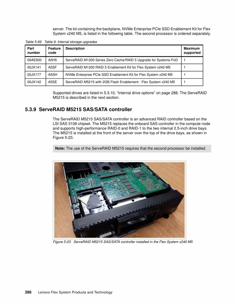
server. The kit containing the backplane, NVMe Enterprise PCIe SSD Enablement Kit for Flex System x240 M5, is listed in the following table. The second processor is ordered separately.
Table 5-69 Table 9. Internal storage upgrades
Supported drives are listed in 5.3.10, “Internal drive options” on page 288. The ServeRAID M5215 is described in the next section.
5.3.9 ServeRAID M5215 SAS/SATA controller
The ServeRAID M5215 SAS/SATA controller is an advanced RAID controller based on the LSI SAS 3108 chipset. The M5215 replaces the onboard SAS controller in the compute node and supports high-performance RAID-0 and RAID-1 to the two internal 2.5-inch drive bays. The M5215 is installed at the front of the server over the top of the drive bays, as shown in Figure 5-23.
Figure 5-23 ServeRAID M5215 SAS/SATA controller installed in the Flex System x240 M5
Partnumber
Featurecode
Description Maximumsupported
00AE930 A5H5 ServeRAID M1200 Series Zero Cache/RAID 5 Upgrade for Systems-FoD 1
00JX141 A5SF ServeRAID M1200 RAID 5 Enablement Kit for Flex System x240 M5 1
00JX177 A5SH NVMe Enterprise PCIe SSD Enablement Kit for Flex System x240 M5 1
00JX142 A5SE ServeRAID M5215 with 2GB Flash Enablement - Flex System x240 M5 1
Note: The use of the ServeRAID M5215 requires that the second processor be installed.
286 Lenovo Flex System Products and Technology
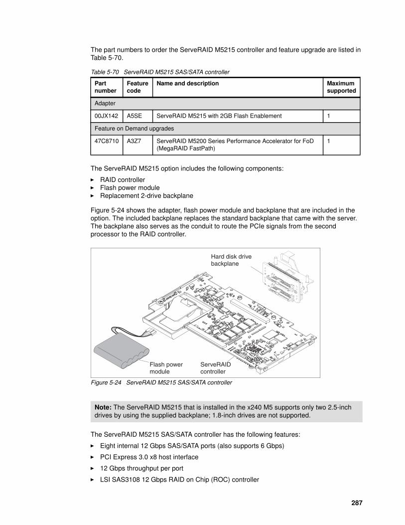
The part numbers to order the ServeRAID M5215 controller and feature upgrade are listed in Table 5-70.
Table 5-70 ServeRAID M5215 SAS/SATA controller
The ServeRAID M5215 option includes the following components:
� RAID controller� Flash power module� Replacement 2-drive backplane
Figure 5-24 shows the adapter, flash power module and backplane that are included in the option. The included backplane replaces the standard backplane that came with the server. The backplane also serves as the conduit to route the PCIe signals from the second processor to the RAID controller.
Figure 5-24 ServeRAID M5215 SAS/SATA controller
The ServeRAID M5215 SAS/SATA controller has the following features:
� Eight internal 12 Gbps SAS/SATA ports (also supports 6 Gbps)
� PCI Express 3.0 x8 host interface
� 12 Gbps throughput per port
� LSI SAS3108 12 Gbps RAID on Chip (ROC) controller
Partnumber
Featurecode
Name and description Maximumsupported
Adapter
00JX142 A5SE ServeRAID M5215 with 2GB Flash Enablement 1
Feature on Demand upgrades
47C8710 A3Z7 ServeRAID M5200 Series Performance Accelerator for FoD (MegaRAID FastPath)
1
Note: The ServeRAID M5215 that is installed in the x240 M5 supports only two 2.5-inch drives by using the supplied backplane; 1.8-inch drives are not supported.
ServeRAIDcontroller
Flash powermodule
Hard disk drivebackplane
287
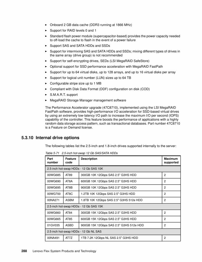
� Onboard 2 GB data cache (DDR3 running at 1866 MHz)
� Support for RAID levels 0 and 1
� Standard flash power module (supercapacitor-based) provides the power capacity needed to off-load the cache to flash in the event of a power failure
� Support SAS and SATA HDDs and SSDs
� Support for intermixing SAS and SATA HDDs and SSDs; mixing different types of drives in the same array (drive group) is not recommended
� Support for self-encrypting drives, SEDs (LSI MegaRAID SafeStore)
� Optional support for SSD performance acceleration with MegaRAID FastPath
� Support for up to 64 virtual disks, up to 128 arrays, and up to 16 virtual disks per array
� Support for logical unit number (LUN) sizes up to 64 TB
� Configurable stripe size up to 1 MB
� Compliant with Disk Data Format (DDF) configuration on disk (COD)
� S.M.A.R.T. support
� MegaRAID Storage Manager management software
The Performance Accelerator upgrade (47C8710), implemented using the LSI MegaRAID FastPath software, provides high-performance I/O acceleration for SSD-based virtual drives by using an extremely low-latency I/O path to increase the maximum I/O per second (IOPS) capability of the controller. This feature boosts the performance of applications with a highly random data storage access pattern, such as transactional databases. Part number 47C8710 is a Feature on Demand license.
5.3.10 Internal drive options
The following tables list the 2.5-inch and 1.8-inch drives supported internally to the server:
Table 5-71 2.5-inch hot-swap 12 Gb SAS/SATA HDDs
Partnumber
Feature code
Description Maximumsupported
2.5-inch hot-swap HDDs - 12 Gb SAS 10K
00WG685 AT89 300GB 10K 12Gbps SAS 2.5" G3HS HDD 2
00WG690 AT8A 600GB 10K 12Gbps SAS 2.5" G3HS HDD 2
00WG695 AT8B 900GB 10K 12Gbps SAS 2.5" G3HS HDD 2
00WG700 AT8C 1.2TB 10K 12Gbps SAS 2.5" G3HS HDD 2
00NA271 ASBM 1.8TB 10K 12Gbps SAS 2.5" G3HS 512e HDD 2
2.5-inch hot-swap HDDs - 12 Gb SAS 15K
00WG660 AT84 300GB 15K 12Gbps SAS 2.5" G3HS HDD 2
00WG665 AT85 600GB 15K 12Gbps SAS 2.5" G3HS HDD 2
01GV035 ASBD 900GB 15K 12Gbps SAS 2.5" G3HS 512e HDD 2
2.5-inch hot-swap HDDs - 12 Gb NL SAS
00NA491 AT7Z 1TB 7.2K 12Gbps NL SAS 2.5" G3HS HDD 2
288 Lenovo Flex System Products and Technology
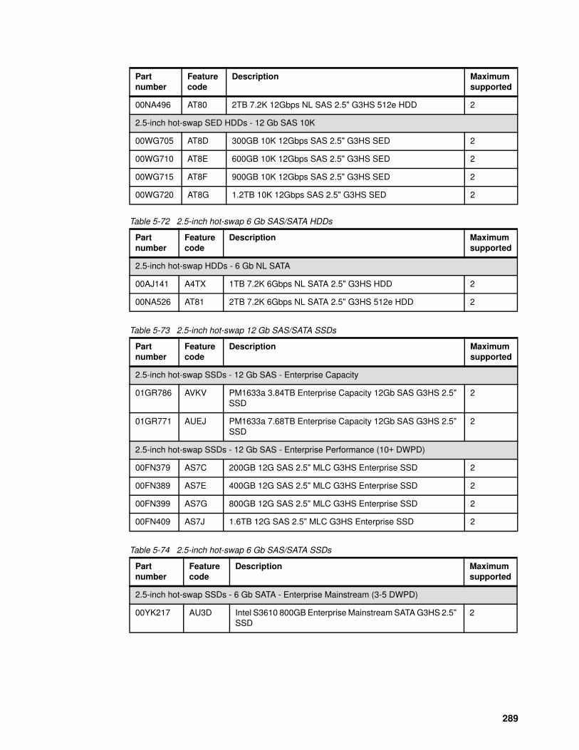
Table 5-72 2.5-inch hot-swap 6 Gb SAS/SATA HDDs
Table 5-73 2.5-inch hot-swap 12 Gb SAS/SATA SSDs
Table 5-74 2.5-inch hot-swap 6 Gb SAS/SATA SSDs
00NA496 AT80 2TB 7.2K 12Gbps NL SAS 2.5" G3HS 512e HDD 2
2.5-inch hot-swap SED HDDs - 12 Gb SAS 10K
00WG705 AT8D 300GB 10K 12Gbps SAS 2.5" G3HS SED 2
00WG710 AT8E 600GB 10K 12Gbps SAS 2.5" G3HS SED 2
00WG715 AT8F 900GB 10K 12Gbps SAS 2.5" G3HS SED 2
00WG720 AT8G 1.2TB 10K 12Gbps SAS 2.5" G3HS SED 2
Partnumber
Feature code
Description Maximumsupported
2.5-inch hot-swap HDDs - 6 Gb NL SATA
00AJ141 A4TX 1TB 7.2K 6Gbps NL SATA 2.5" G3HS HDD 2
00NA526 AT81 2TB 7.2K 6Gbps NL SATA 2.5" G3HS 512e HDD 2
Partnumber
Feature code
Description Maximumsupported
2.5-inch hot-swap SSDs - 12 Gb SAS - Enterprise Capacity
01GR786 AVKV PM1633a 3.84TB Enterprise Capacity 12Gb SAS G3HS 2.5" SSD
2
01GR771 AUEJ PM1633a 7.68TB Enterprise Capacity 12Gb SAS G3HS 2.5" SSD
2
2.5-inch hot-swap SSDs - 12 Gb SAS - Enterprise Performance (10+ DWPD)
00FN379 AS7C 200GB 12G SAS 2.5" MLC G3HS Enterprise SSD 2
00FN389 AS7E 400GB 12G SAS 2.5" MLC G3HS Enterprise SSD 2
00FN399 AS7G 800GB 12G SAS 2.5" MLC G3HS Enterprise SSD 2
00FN409 AS7J 1.6TB 12G SAS 2.5" MLC G3HS Enterprise SSD 2
Partnumber
Feature code
Description Maximumsupported
2.5-inch hot-swap SSDs - 6 Gb SATA - Enterprise Mainstream (3-5 DWPD)
00YK217 AU3D Intel S3610 800GB Enterprise Mainstream SATA G3HS 2.5" SSD
2
Partnumber
Feature code
Description Maximumsupported
289
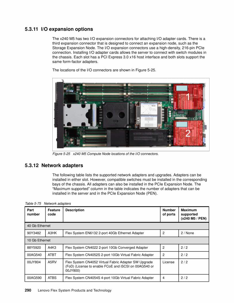
5.3.11 I/O expansion options
The x240 M5 has two I/O expansion connectors for attaching I/O adapter cards. There is a third expansion connector that is designed to connect an expansion node, such as the Storage Expansion Node. The I/O expansion connectors use a high-density, 216-pin PCIe connection. Installing I/O adapter cards allows the server to connect with switch modules in the chassis. Each slot has a PCI Express 3.0 x16 host interface and both slots support the same form-factor adapters.
The locations of the I/O connectors are shown in Figure 5-25.
Figure 5-25 x240 M5 Compute Node locations of the I/O connectors.
5.3.12 Network adapters
The following table lists the supported network adapters and upgrades. Adapters can be installed in either slot. However, compatible switches must be installed in the corresponding bays of the chassis. All adapters can also be installed in the PCIe Expansion Node. The “Maximum supported” column in the table indicates the number of adapters that can be installed in the server and in the PCIe Expansion Node (PEN).
Table 5-75 Network adapters
2
1
Partnumber
Featurecode
Description Numberof ports
Maximumsupported(x240 M5 / PEN)
40 Gb Ethernet
90Y3482 A3HK Flex System EN6132 2-port 40Gb Ethernet Adapter 2 2 / None
10 Gb Ethernet
88Y5920 A4K3 Flex System CN4022 2-port 10Gb Converged Adapter 2 2 / 2
00AG540 ATBT Flex System CN4052S 2-port 10Gb Virtual Fabric Adapter 2 2 / 2
00JY804 A5RV Flex System CN4052 Virtual Fabric Adapter SW Upgrade (FoD) (License to enable FCoE and iSCSI on 00AG540 or 00JY800)
License 2 / 2
00AG590 ATBS Flex System CN4054S 4-port 10Gb Virtual Fabric Adapter 4 2 / 2
290 Lenovo Flex System Products and Technology
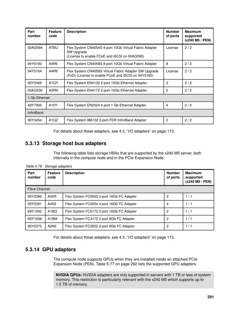
For details about these adapters, see 4.3, “I/O adapters” on page 173.
5.3.13 Storage host bus adapters
The following table lists storage HBAs that are supported by the x240 M5 server, both internally in the compute node and in the PCIe Expansion Node.
Table 5-76 Storage adapters
For details about these adapters, see 4.3, “I/O adapters” on page 173.
5.3.14 GPU adapters
The compute node supports GPUs when they are installed inside an attached PCIe Expansion Node (PEN). Table 5-77 on page 292 lists the supported GPU adapters.
00AG594 ATBU Flex System CN4054S 4-port 10Gb Virtual Fabric Adapter SW Upgrade(License to enable FCoE and iSCSI on 00AG590)
License 2 / 2
94Y5160 A4R6 Flex System CN4058S 8-port 10Gb Virtual Fabric Adapter 8 2 / 2
94Y5164 A4R9 Flex System CN4058S Virtual Fabric Adapter SW Upgrade (FoD) (License to enable FCoE and iSCSI on 94Y5160)
License 2 / 2
90Y3466 A1QY Flex System EN4132 2-port 10Gb Ethernet Adapter 2 2 / 2
00AG530 A5RN Flex System EN4172 2-port 10Gb Ethernet Adapter 2 2 / 2
1 Gb Ethernet
49Y7900 A10Y Flex System EN2024 4-port 1 Gb Ethernet Adapter 4 2 / 2
InfiniBand
90Y3454 A1QZ Flex System IB6132 2-port FDR InfiniBand Adapter 2 2 / 2
Partnumber
Featurecode
Description Numberof ports
Maximumsupported(x240 M5 / PEN)
Partnumber
Featurecode
Description Numberof ports
Maximumsupported(x240 M5 / PEN)
Fibre Channel
95Y2386 A45R Flex System FC5052 2-port 16Gb FC Adapter 2 1 / 1
95Y2391 A45S Flex System FC5054 4-port 16Gb FC Adapter 4 1 / 1
69Y1942 A1BQ Flex System FC5172 2-port 16Gb FC Adapter 2 1 / 1
69Y1938 A1BM Flex System FC3172 2-port 8Gb FC Adapter 2 1 / 1
95Y2375 A2N5 Flex System FC3052 2-port 8Gb FC Adapter 2 1 / 1
NVIDIA GPUs: NVIDIA adapters are only supported in servers with 1 TB or less of system memory. This restriction is particularly relevant with the x240 M5 which supports up to 1.5 TB of memory.
291
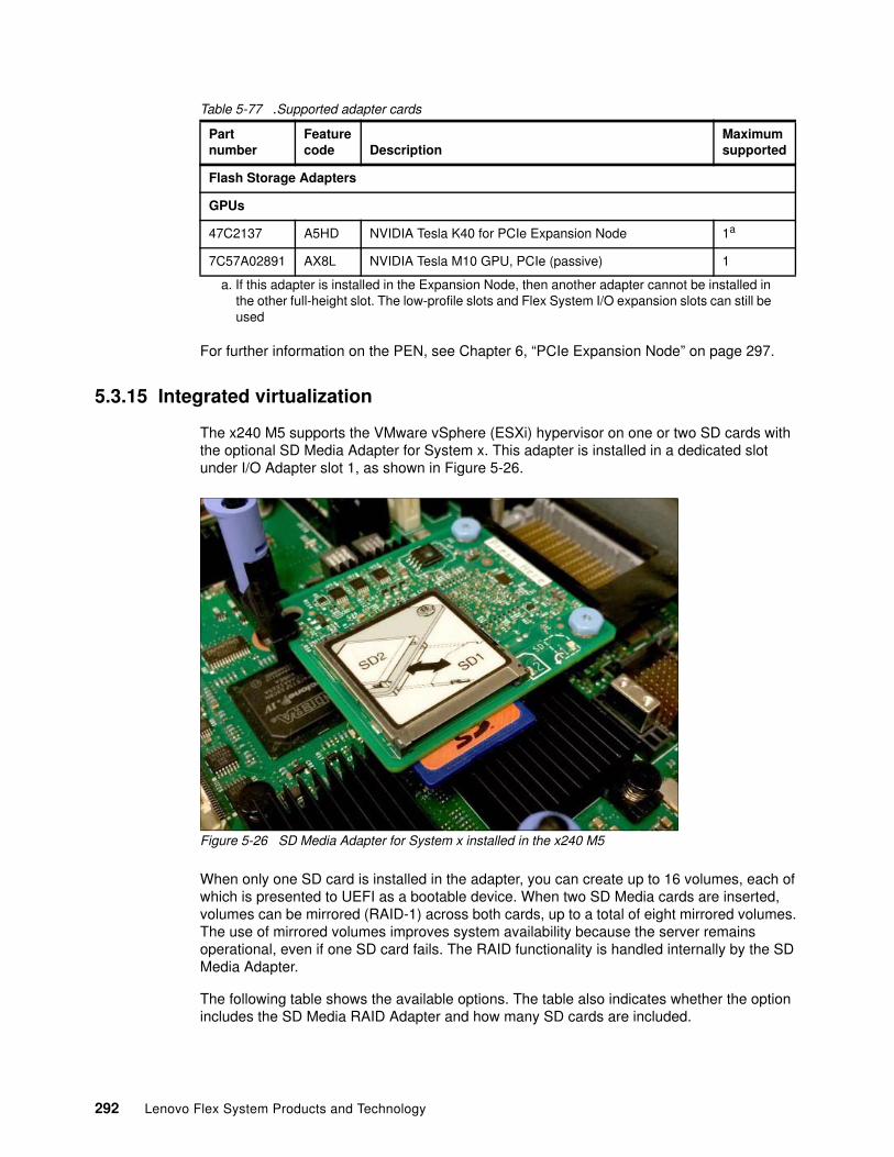
Table 5-77 .Supported adapter cards
For further information on the PEN, see Chapter 6, “PCIe Expansion Node” on page 297.
5.3.15 Integrated virtualization
The x240 M5 supports the VMware vSphere (ESXi) hypervisor on one or two SD cards with the optional SD Media Adapter for System x. This adapter is installed in a dedicated slot under I/O Adapter slot 1, as shown in Figure 5-26.
Figure 5-26 SD Media Adapter for System x installed in the x240 M5
When only one SD card is installed in the adapter, you can create up to 16 volumes, each of which is presented to UEFI as a bootable device. When two SD Media cards are inserted, volumes can be mirrored (RAID-1) across both cards, up to a total of eight mirrored volumes. The use of mirrored volumes improves system availability because the server remains operational, even if one SD card fails. The RAID functionality is handled internally by the SD Media Adapter.
The following table shows the available options. The table also indicates whether the option includes the SD Media RAID Adapter and how many SD cards are included.
Partnumber
Featurecode Description
Maximumsupported
Flash Storage Adapters
GPUs
47C2137 A5HD NVIDIA Tesla K40 for PCIe Expansion Node 1a
a. If this adapter is installed in the Expansion Node, then another adapter cannot be installed in the other full-height slot. The low-profile slots and Flex System I/O expansion slots can still be used
7C57A02891 AX8L NVIDIA Tesla M10 GPU, PCIe (passive) 1
292 Lenovo Flex System Products and Technology
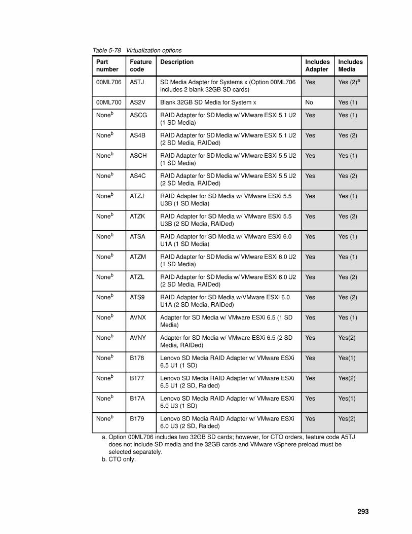
Table 5-78 Virtualization options
Partnumber
Featurecode
Description IncludesAdapter
IncludesMedia
00ML706 A5TJ SD Media Adapter for Systems x (Option 00ML706 includes 2 blank 32GB SD cards)
Yes Yes (2)a
a. Option 00ML706 includes two 32GB SD cards; however, for CTO orders, feature code A5TJ does not include SD media and the 32GB cards and VMware vSphere preload must be selected separately.
00ML700 AS2V Blank 32GB SD Media for System x No Yes (1)
Noneb
b. CTO only.
ASCG RAID Adapter for SD Media w/ VMware ESXi 5.1 U2 (1 SD Media)
Yes Yes (1)
Noneb AS4B RAID Adapter for SD Media w/ VMware ESXi 5.1 U2 (2 SD Media, RAIDed)
Yes Yes (2)
Noneb ASCH RAID Adapter for SD Media w/ VMware ESXi 5.5 U2 (1 SD Media)
Yes Yes (1)
Noneb AS4C RAID Adapter for SD Media w/ VMware ESXi 5.5 U2 (2 SD Media, RAIDed)
Yes Yes (2)
Noneb ATZJ RAID Adapter for SD Media w/ VMware ESXi 5.5 U3B (1 SD Media)
Yes Yes (1)
Noneb ATZK RAID Adapter for SD Media w/ VMware ESXi 5.5 U3B (2 SD Media, RAIDed)
Yes Yes (2)
Noneb ATSA RAID Adapter for SD Media w/ VMware ESXi 6.0 U1A (1 SD Media)
Yes Yes (1)
Noneb ATZM RAID Adapter for SD Media w/ VMware ESXi 6.0 U2 (1 SD Media)
Yes Yes (1)
Noneb ATZL RAID Adapter for SD Media w/ VMware ESXi 6.0 U2 (2 SD Media, RAIDed)
Yes Yes (2)
Noneb ATS9 RAID Adapter for SD Media w/VMware ESXi 6.0 U1A (2 SD Media, RAIDed)
Yes Yes (2)
Noneb AVNX Adapter for SD Media w/ VMware ESXi 6.5 (1 SD Media)
Yes Yes (1)
Noneb AVNY Adapter for SD Media w/ VMware ESXi 6.5 (2 SD Media, RAIDed)
Yes Yes(2)
Noneb B178 Lenovo SD Media RAID Adapter w/ VMware ESXi 6.5 U1 (1 SD)
Yes Yes(1)
Noneb B177 Lenovo SD Media RAID Adapter w/ VMware ESXi 6.5 U1 (2 SD, Raided)
Yes Yes(2)
Noneb B17A Lenovo SD Media RAID Adapter w/ VMware ESXi 6.0 U3 (1 SD)
Yes Yes(1)
Noneb B179 Lenovo SD Media RAID Adapter w/ VMware ESXi 6.0 U3 (2 SD, Raided)
Yes Yes(2)
293
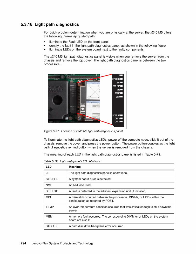
5.3.16 Light path diagnostics
For quick problem determination when you are physically at the server, the x240 M5 offers the following three-step guided path:
� Illuminate the Fault LED on the front panel.� Identify the fault in the light path diagnostics panel, as shown in the following figure.� Illuminate LEDs on the system board next to the faulty components.
The x240 M5 light path diagnostics panel is visible when you remove the server from the chassis and remove the top cover. The light path diagnostics panel is between the two processors.
Figure 5-27 Location of x240 M5 light path diagnostics panel
To illuminate the light path diagnostics LEDs, power off the compute node, slide it out of the chassis, remove the cover, and press the power button. The power button doubles as the light path diagnostics remind button when the server is removed from the chassis.
The meaning of each LED in the light path diagnostics panel is listed in Table 5-79.
Table 5-79 Light path panel LED definitions
LED Meaning
LP The light path diagnostics panel is operational.
SYS BRD A system board error is detected.
NMI An NMI occurred.
SEE EXP A fault is detected in the adjacent expansion unit (if installed).
MIS A mismatch occurred between the processors, DIMMs, or HDDs within the configuration as reported by POST.
TEMP An over-temperature condition occurred that was critical enough to shut down the server.
MEM A memory fault occurred. The corresponding DIMM error LEDs on the system board are also lit.
STOR BP A hard disk drive backplane error occurred.
294 Lenovo Flex System Products and Technology
5.3.17 Operating system support
The server supports the following operating systems:
� Microsoft Windows Server 2012� Microsoft Windows Server 2012 R2� Microsoft Windows Server 2016� Microsoft Windows Server, version 1709� Red Hat Enterprise Linux 6.7 x64� Red Hat Enterprise Linux 6.8 x64� Red Hat Enterprise Linux 7.2� Red Hat Enterprise Linux 7.3� Red Hat Enterprise Linux 7.4� SUSE Linux Enterprise Server 11 Xen x64 SP4� SUSE Linux Enterprise Server 11 x64 SP4� SUSE Linux Enterprise Server 12 SP1� SUSE Linux Enterprise Server 12 SP2� SUSE Linux Enterprise Server 12 SP3� SUSE Linux Enterprise Server 12 Xen SP1� SUSE Linux Enterprise Server 12 Xen SP2� SUSE Linux Enterprise Server 12 Xen SP3� VMware ESXi 5.5 U3� VMware ESXi 6.0 U2� VMware ESXi 6.0 U3� VMware ESXi 6.5� VMware ESXi 6.5 U1
For a complete list of supported, certified and tested operating systems, plus additional details and links to relevant web sites, see the Operating System Interoperability Guide:
https://lenovopress.com/osig#servers=x240-m5-9532-e5-v4
5.3.18 Physical specifications
The server features the following dimensions and weight (approximate):
� Height: 51 mm (2.0 in)� Depth: 493 mm (19.4 in)� Width: 215 mm (8.5 in)� Maximum weight: 7.1 kg (15.6 lb)
The server features the following shipping dimensions and weight (approximate):
� Height: 197 mm (7.8 in)� Depth: 603 mm (23.7 in)� Width: 430 mm (16.9 in)� Weight: 8 kg (17.6 lb)
5.3.19 Supported environment
The Flex System x240 M5 compute node complies with ASHRAE Class A3 specifications.
CPU 1/2 A microprocessor failed or overheated or the start microprocessor (CPU 1) is missing. The fault LED on the front panel is also lit.
LED Meaning
295
The following Power on operating environment is supported:
� Temperature: 5 - 40 °C (41 - 104 °F)� Humidity, non-condensing: -12 °C dew point (10.4 °F) and 8 - 85% relative humidity� Maximum dew point: 24 °C (75 °F)� Maximum altitude: 3048 m (10,000 ft)� Maximum rate of temperature change: 5 °C/hr (41 °F/hr)
The following power-off operating environment is supported:
� Temperature: 5 - 45 °C (41 - 113 °F)� Relative humidity: 8 - 85%� Maximum dew point: 27 °C (80.6 °F)
The following Storage (non-operating) operating environment is supported:
� Temperature: 1 - 60 °C (33.8 - 140 °F)� Altitude: 3050 m (10,006 ft)� Relative humidity: 5 - 80%� Maximum dew point: 29 °C (84.2°F)
The following Shipment (non-operating) environment is supported:
� Temperature: -40 - 60 °C (-40 - 140 °F)� Altitude: 10,700 m (35,105 ft)� Relative humidity: 5 - 100%� Maximum dew point: 29 °C (84.2 °F)
296 Lenovo Flex System Products and Technology
Chapter 6. PCIe Expansion Node
The Flex System PCIe Expansion Node (PEN) attaches to an x240 M5 compute node and allows the expansion of the nodes’ capabilities with locally attached storage or PCIe adapters.
The PCIe Expansion Node supports up to four PCIe adapters and two other Flex System I/O expansion adapters.
This chapter includes the following topics:
� 6.1, “Introduction” on page 298� 6.2, “Features” on page 299� 6.3, “Architecture” on page 302� 6.4, “Supported PCIe adapters” on page 303� 6.5, “Supported I/O expansion cards” on page 304
6
Note: The only compute node currently available that supports the PEN is the x240 M5 (9532). The SN550 and SN850 servers do not have an expansion connector and thus do not support attachment of the PEN.
© Copyright Lenovo 2018. All rights reserved. 297
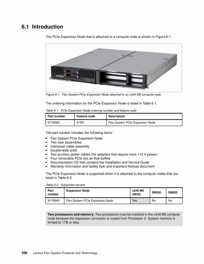
6.1 Introduction
The PCIe Expansion Node that is attached to a compute node is shown in Figure 6-1.
Figure 6-1 Flex System PCIe Expansion Node attached to an x240 M5 compute node
The ordering information for the PCIe Expansion Node is listed in Table 6-1.
Table 6-1 PCIe Expansion Node ordering number and feature code
The part number includes the following items:
� Flex System PCIe Expansion Node� Two riser assemblies� Interposer cable assembly� Double-wide shelf� Two auxiliary power cables (for adapters that require more +12 V power)� Four removable PCIe slot air flow baffles� Documentation CD that contains the Installation and Service Guide� Warranty information and Safety flyer and Important Notices document
The PCIe Expansion Node is supported when it is attached to the compute nodes that are listed in Table 6-2.
Table 6-2 Supported servers
Part number Feature code Description
81Y8983 A1BV Flex System PCIe Expansion Node
Partnumber
Expansion Node x240 M5 (9532)
SN550 SN850
81Y8983 Flex System PCIe Expansion Node Yes No No
Two processors and memory: Two processors must be installed in the x240 M5 compute node because the expansion connector is routed from Processor 2. System memory is limited to 1TB or less.
298 Lenovo Flex System Products and Technology
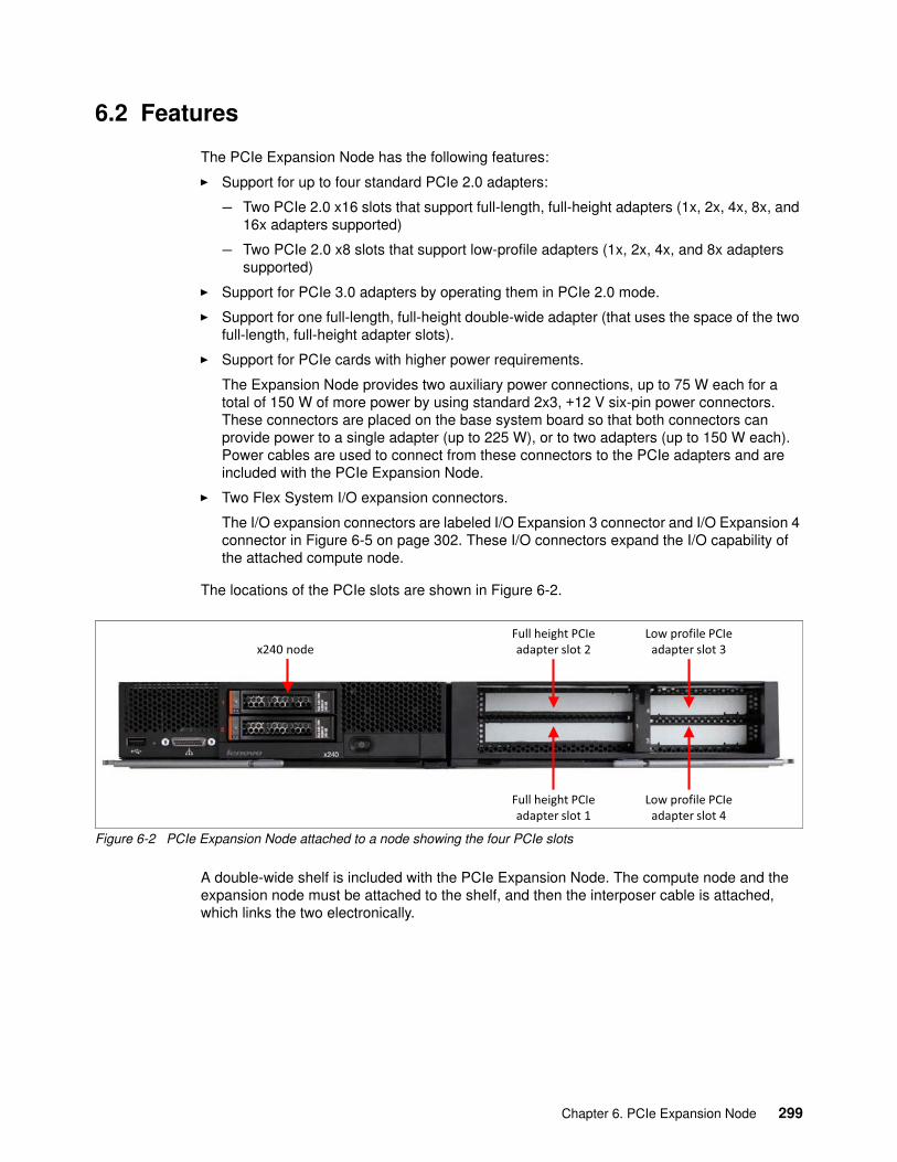
6.2 Features
The PCIe Expansion Node has the following features:
� Support for up to four standard PCIe 2.0 adapters:
– Two PCIe 2.0 x16 slots that support full-length, full-height adapters (1x, 2x, 4x, 8x, and 16x adapters supported)
– Two PCIe 2.0 x8 slots that support low-profile adapters (1x, 2x, 4x, and 8x adapters supported)
� Support for PCIe 3.0 adapters by operating them in PCIe 2.0 mode.
� Support for one full-length, full-height double-wide adapter (that uses the space of the two full-length, full-height adapter slots).
� Support for PCIe cards with higher power requirements.
The Expansion Node provides two auxiliary power connections, up to 75 W each for a total of 150 W of more power by using standard 2x3, +12 V six-pin power connectors. These connectors are placed on the base system board so that both connectors can provide power to a single adapter (up to 225 W), or to two adapters (up to 150 W each). Power cables are used to connect from these connectors to the PCIe adapters and are included with the PCIe Expansion Node.
� Two Flex System I/O expansion connectors.
The I/O expansion connectors are labeled I/O Expansion 3 connector and I/O Expansion 4 connector in Figure 6-5 on page 302. These I/O connectors expand the I/O capability of the attached compute node.
The locations of the PCIe slots are shown in Figure 6-2.
Figure 6-2 PCIe Expansion Node attached to a node showing the four PCIe slots
A double-wide shelf is included with the PCIe Expansion Node. The compute node and the expansion node must be attached to the shelf, and then the interposer cable is attached, which links the two electronically.
x240 nodeFull height PCIeadapter slot 2
Low profile PCIeadapter slot 3
Full height PCIeadapter slot 1
Low profile PCIeadapter slot 4
Chapter 6. PCIe Expansion Node 299
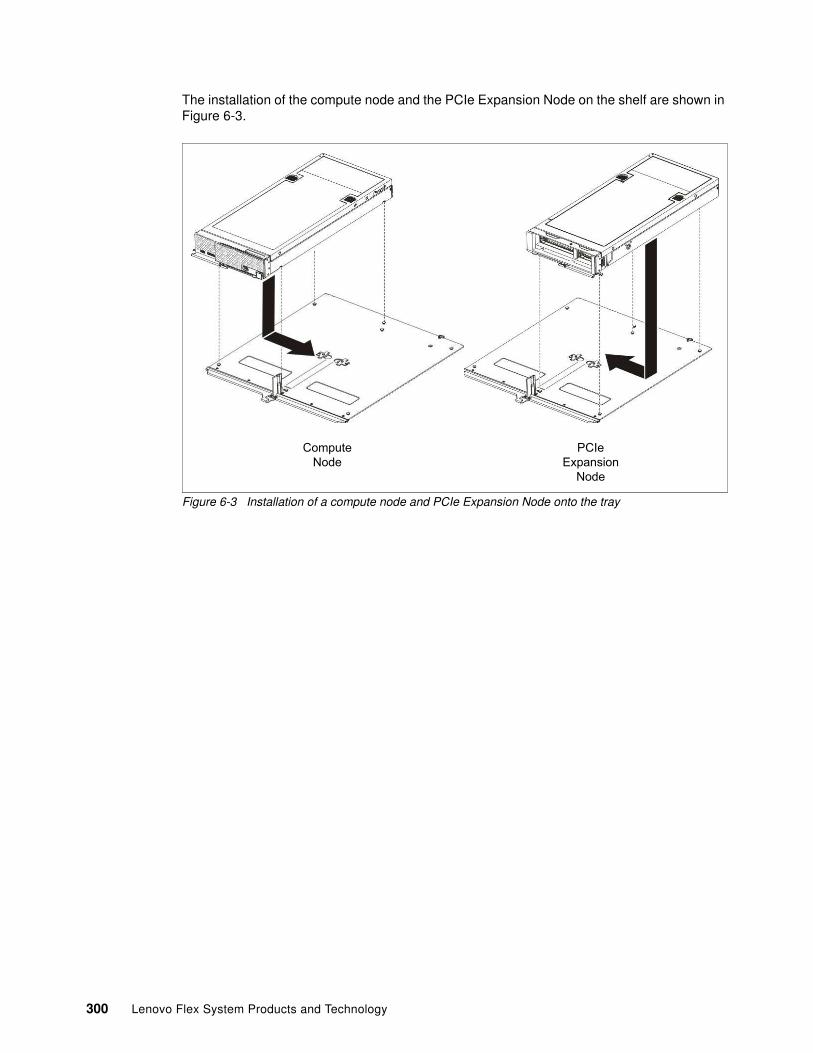
The installation of the compute node and the PCIe Expansion Node on the shelf are shown in Figure 6-3.
Figure 6-3 Installation of a compute node and PCIe Expansion Node onto the tray
ComputeNode
PCIeExpansion
Node
300 Lenovo Flex System Products and Technology
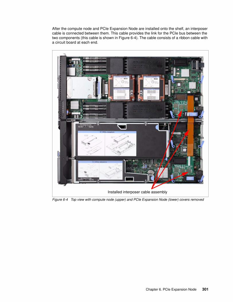
After the compute node and PCIe Expansion Node are installed onto the shelf, an interposer cable is connected between them. This cable provides the link for the PCIe bus between the two components (this cable is shown in Figure 6-4). The cable consists of a ribbon cable with a circuit board at each end.
Figure 6-4 Top view with compute node (upper) and PCIe Expansion Node (lower) covers removed
Installed interposer cable assembly
Chapter 6. PCIe Expansion Node 301
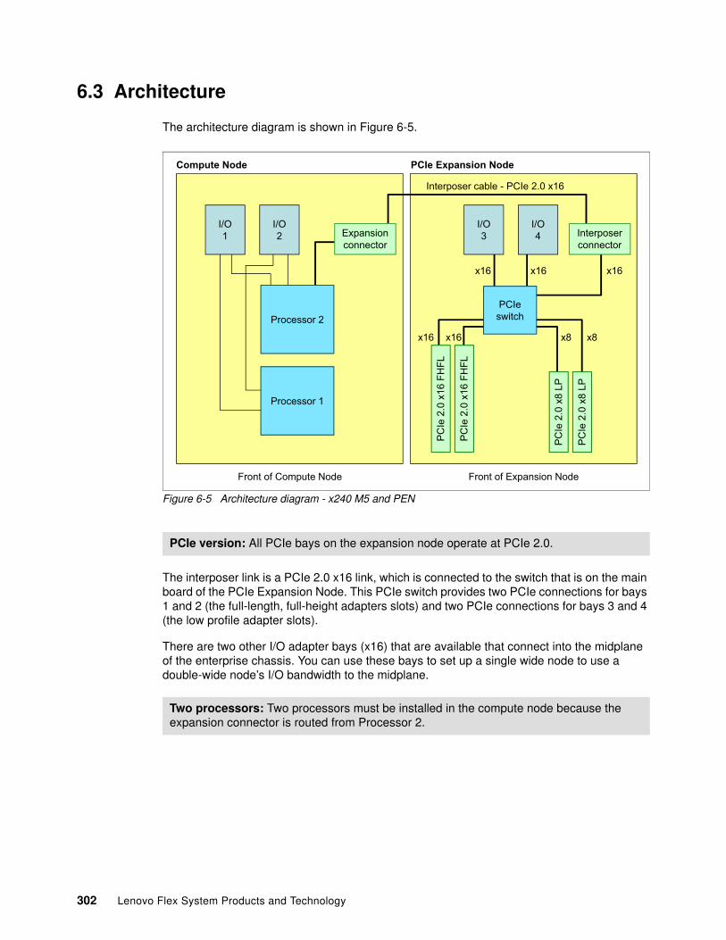
6.3 Architecture
The architecture diagram is shown in Figure 6-5.
Figure 6-5 Architecture diagram - x240 M5 and PEN
The interposer link is a PCIe 2.0 x16 link, which is connected to the switch that is on the main board of the PCIe Expansion Node. This PCIe switch provides two PCIe connections for bays 1 and 2 (the full-length, full-height adapters slots) and two PCIe connections for bays 3 and 4 (the low profile adapter slots).
There are two other I/O adapter bays (x16) that are available that connect into the midplane of the enterprise chassis. You can use these bays to set up a single wide node to use a double-wide node’s I/O bandwidth to the midplane.
PCIe version: All PCIe bays on the expansion node operate at PCIe 2.0.
Two processors: Two processors must be installed in the compute node because the expansion connector is routed from Processor 2.
I/O3
I/O4
PCIeswitch
PC
Ie 2
.0 x
16 F
HFL
PC
Ie 2
.0 x
16 F
HFL
PC
Ie 2
.0 x
8 LP
PC
Ie 2
.0 x
8 LP
Expansionconnector
Interposerconnector
Interposer cable - PCIe 2.0 x16
x16
x8
x16x16
x16 x8x16
Compute Node PCIe Expansion Node
Front of Compute Node Front of Expansion Node
I/O1
I/O2
Processor 2
Processor 1
302 Lenovo Flex System Products and Technology
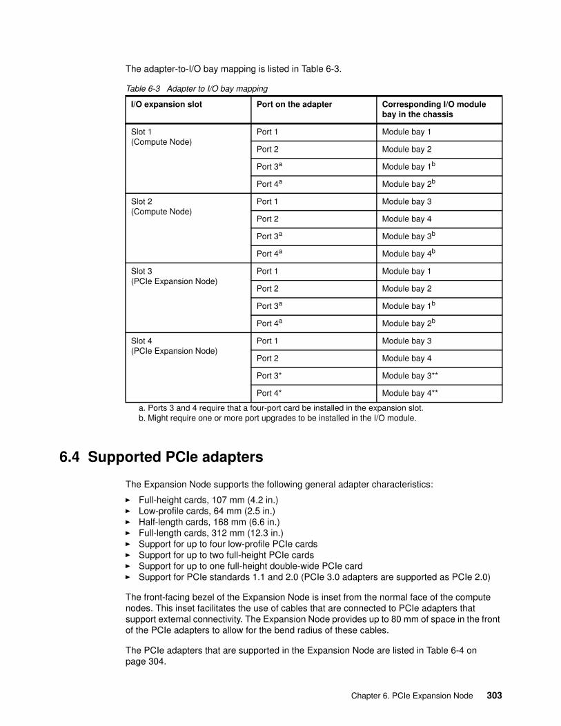
The adapter-to-I/O bay mapping is listed in Table 6-3.
Table 6-3 Adapter to I/O bay mapping
6.4 Supported PCIe adapters
The Expansion Node supports the following general adapter characteristics:
� Full-height cards, 107 mm (4.2 in.)� Low-profile cards, 64 mm (2.5 in.)� Half-length cards, 168 mm (6.6 in.)� Full-length cards, 312 mm (12.3 in.)� Support for up to four low-profile PCIe cards� Support for up to two full-height PCIe cards� Support for up to one full-height double-wide PCIe card� Support for PCIe standards 1.1 and 2.0 (PCIe 3.0 adapters are supported as PCIe 2.0)
The front-facing bezel of the Expansion Node is inset from the normal face of the compute nodes. This inset facilitates the use of cables that are connected to PCIe adapters that support external connectivity. The Expansion Node provides up to 80 mm of space in the front of the PCIe adapters to allow for the bend radius of these cables.
The PCIe adapters that are supported in the Expansion Node are listed in Table 6-4 on page 304.
I/O expansion slot Port on the adapter Corresponding I/O module bay in the chassis
Slot 1(Compute Node)
Port 1 Module bay 1
Port 2 Module bay 2
Port 3a
a. Ports 3 and 4 require that a four-port card be installed in the expansion slot.
Module bay 1b
b. Might require one or more port upgrades to be installed in the I/O module.
Port 4a Module bay 2b
Slot 2(Compute Node)
Port 1 Module bay 3
Port 2 Module bay 4
Port 3a Module bay 3b
Port 4a Module bay 4b
Slot 3(PCIe Expansion Node)
Port 1 Module bay 1
Port 2 Module bay 2
Port 3a Module bay 1b
Port 4a Module bay 2b
Slot 4(PCIe Expansion Node)
Port 1 Module bay 3
Port 2 Module bay 4
Port 3* Module bay 3**
Port 4* Module bay 4**
Chapter 6. PCIe Expansion Node 303
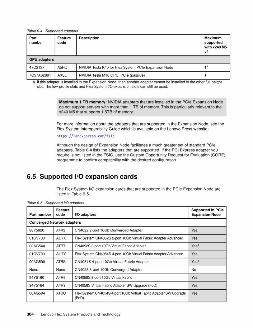
Table 6-4 Supported adapters
For more information about the adapters that are supported in the Expansion Node, see the Flex System Interoperability Guide which is available on the Lenovo Press website:
https://lenovopress.com/fsig
Although the design of Expansion Node facilitates a much greater set of standard PCIe adapters, Table 6-4 lists the adapters that are supported. If the PCI Express adapter you require is not listed in the FSIG, use the Custom Opportunity Request for Evaluation (CORE) programme to confirm compatibility with the desired configuration.
6.5 Supported I/O expansion cards
The Flex System I/O expansion cards that are supported in the PCIe Expansion Node are listed in Table 6-5.
Table 6-5 Supported I/O adapters
Partnumber
Featurecode
Description Maximumsupportedwith x240 M5 v4
GPU adapters
47C2137 A5HD NVIDIA Tesla K40 for Flex System PCIe Expansion Node 1a
a. If this adapter is installed in the Expansion Node, then another adapter cannot be installed in the other full-height slot. The low-profile slots and Flex System I/O expansion slots can still be used.
7C57A02891 AX8L NVIDIA Tesla M10 GPU, PCIe (passive) 1
Maximum 1 TB memory: NVIDIA adapters that are installed in the PCIe Expansion Node do not support servers with more than 1 TB of memory. This is particularly relevant to the x240 M5 that supports 1.5TB of memory.
Part numberFeaturecode I/O adapters
Supported in PCIeExpansion Node
Converged Network adapters
88Y5920 A4K3 CN4022 2-port 10Gb Converged Adapter Yes
01CV780 AU7X Flex System CN4052S 2-port 10Gb Virtual Fabric Adapter Advanced Yes
00AG540 ATBT CN4052S 2-port 10Gb Virtual Fabric Adapter Yesa
01CV790 AU7Y Flex System CN4054S 4-port 10Gb Virtual Fabric Adapter Advanced Yes
00AG590 ATBS CN4054S 4-port 10Gb Virtual Fabric Adapter Yesa
None None CN4058 8-port 10Gb Converged Adapter No
94Y5160 A4R6 CN4058S 8-port 10Gb Virtual Fabric Yes
94Y5164 A4R9 CN4058S Virtual Fabric Adapter SW Upgrade (FoD) Yes
00AG594 ATBU Flex System CN4054S 4-port 10Gb Virtual Fabric Adapter SW Upgrade (FoD)
Yes
304 Lenovo Flex System Products and Technology
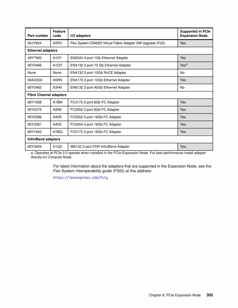
For latest information about the adapters that are supported in the Expansion Node, see the Flex System Interoperability guide (FSIG) at this address:
https://lenovopress.com/fsig
00JY804 A5RV Flex System CN4052 Virtual Fabric Adapter SW Upgrade (FoD) Yes
Ethernet adapters
49Y7900 A10Y EN2024 4-port 1Gb Ethernet Adapter Yes
90Y3466 A1QY EN4132 2-port 10 Gb Ethernet Adapter Yesa
None None EN4132 2-port 10Gb RoCE Adapter No
00AG530 A5RN EN4172 2-port 10Gb Ethernet Adapter Yes
90Y3482 A3HK EN6132 2-port 40Gb Ethernet Adapter No
Fibre Channel adapters
69Y1938 A1BM FC3172 2-port 8Gb FC Adapter Yes
95Y2375 A2N5 FC3052 2-port 8Gb FC Adapter Yes
95Y2386 A45R FC5052 2-port 16Gb FC Adapter Yes
95Y2391 A45S FC5054 4-port 16Gb FC Adapter Yes
69Y1942 A1BQ FC5172 2-port 16Gb FC Adapter Yes
InfiniBand adapters
90Y3454 A1QZ IB6132 2-port FDR InfiniBand Adapter Yes
a. Operates at PCIe 2.0 speeds when installed in the PCIe Expansion Node. For best performance install adapterdirectly on Compute Node.
Part numberFeaturecode I/O adapters
Supported in PCIeExpansion Node
Chapter 6. PCIe Expansion Node 305

306 Lenovo Flex System Products and Technology
Chapter 7. Network integration
This chapter describes basic and advanced networking techniques that can be deployed with Flex System platform in a data center to meet availability, performance, scalability, and systems management goals.
This chapter includes the following topics:
� 7.1, “Choosing the Ethernet switch I/O module” on page 308� 7.2, “Virtual local area networks” on page 310� 7.3, “Scalability and port flexibility” on page 312� 7.4, “Flex System Interconnect Fabric” on page 316� 7.5, “High Availability” on page 318� 7.6, “FCoE capabilities” on page 329� 7.7, “vNIC solution capabilities” on page 330� 7.8, “Unified Fabric Port feature” on page 334� 7.9, “Easy Connect concept” on page 336� 7.10, “Stacking feature” on page 338� 7.11, “OpenFlow support” on page 340� 7.12, “802.1Qbg Edge Virtual Bridge support” on page 340� 7.13, “SPAR feature” on page 341� 7.14, “Management” on page 342� 7.15, “Summary and conclusions” on page 343
7
© Copyright Lenovo 2018. All rights reserved. 307
7.1 Choosing the Ethernet switch I/O module
Selecting the Ethernet I/O module that is best for an environment is a process that is unique to each client. The following factors should be considered when you are deciding which Ethernet model is right for a specific environment:
� The first decision is regarding speed requirements. Do you need only 1 Gb connectivity to the servers, or is 10 Gb to the servers a requirement? Consider the following factors:
– If there is no immediate need for 10 Gb to the servers, there are no plans to upgrade to 10 Gb in the foreseeable future, and you have no need for any of the advanced features that are offered in the 10 Gb products, the EN2092 1Gb Ethernet Switch is a possible solution.
– If you need a solution that has 10 Gb Ethernet to the server, is not apparent to the network, has only a single link for each compute node for each I/O module, and requires direct connections from the compute node to the external ToR switch, the EN4091 10Gb Ethernet Pass-thru is a viable option.
– If you need 10 Gb today or know that you need 10 Gb soon, need more than one 10 G link from each switch bay to each compute node, or need any of the features that are associated with 10 Gb server interfaces, such as FCoE and switched-based vNIC support, you have a choice of EN4093R 10Gb Scalable Switch, the CN4093 10Gb Converged Scalable Switch, the EN 4024 10Gb Scalable switch, or the SI4093 System Interconnect Module.
The following considerations are important when you are selecting between the EN4093R 10Gb Scalable Switch, the CN4093 10Gb Converged Scalable Switch, and the SI4093 System Interconnect Module:
� If you require Fibre Channel Forwarder (FCF) services within the Enterprise Chassis or native Fibre Channel uplinks from the 10 G switch, the CN4093 10Gb Converged Scalable Switch is the correct choice.
� If you do not require FCF services or native Fibre Channel ports on the 10 G switch but need the maximum number of 10 G uplinks without purchasing an extra license, support for FCoE transit capabilities (and the most feature-rich solution) the EN4093R 10Gb Scalable Switch is a good choice.
� If you require ready for use not apparent operation (minimal to no configuration on the switch), and do not need any L3 support or other advanced features (and know that there is no need for more advanced functions), the SI4093 System Interconnect Module is a potential choice.
For customers that implement a Cisco networking environment, Flex System now offers the Cisco Nexus B22 Fabric Extender (FEX) for Nexus connectivity inside the Flex System chassis.
The FEX offers easy connectivity to a customer’s Nexus infrastructure. This FEX is not managed by XClarity, however, it is recognized within the CMM for power management and alerting capabilities. The FEX is managed fully by the Nexus Fabric, and might be considered where clients want to deploy Cisco technology inside a Flex System chassis but does not allow anything other than Cisco networking attached to their infrastructure.
308 Lenovo Flex System Products and Technology
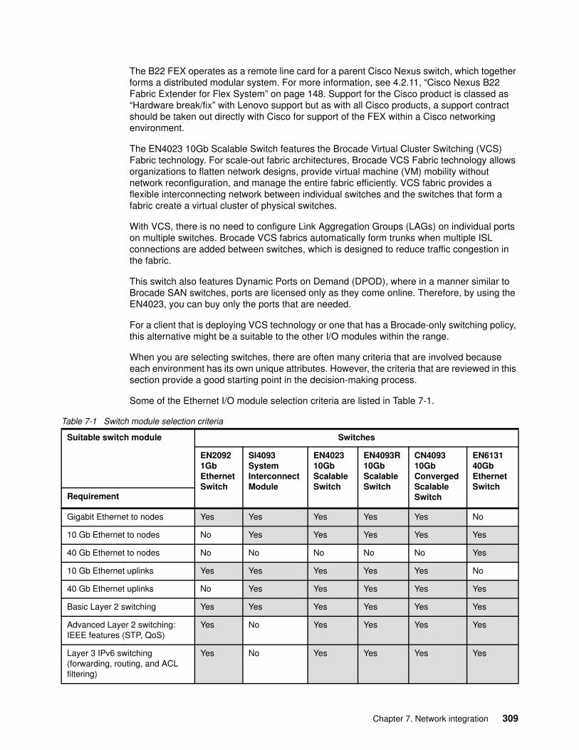
The B22 FEX operates as a remote line card for a parent Cisco Nexus switch, which together forms a distributed modular system. For more information, see 4.2.11, “Cisco Nexus B22 Fabric Extender for Flex System” on page 148. Support for the Cisco product is classed as “Hardware break/fix” with Lenovo support but as with all Cisco products, a support contract should be taken out directly with Cisco for support of the FEX within a Cisco networking environment.
The EN4023 10Gb Scalable Switch features the Brocade Virtual Cluster Switching (VCS) Fabric technology. For scale-out fabric architectures, Brocade VCS Fabric technology allows organizations to flatten network designs, provide virtual machine (VM) mobility without network reconfiguration, and manage the entire fabric efficiently. VCS fabric provides a flexible interconnecting network between individual switches and the switches that form a fabric create a virtual cluster of physical switches.
With VCS, there is no need to configure Link Aggregation Groups (LAGs) on individual ports on multiple switches. Brocade VCS fabrics automatically form trunks when multiple ISL connections are added between switches, which is designed to reduce traffic congestion in the fabric.
This switch also features Dynamic Ports on Demand (DPOD), where in a manner similar to Brocade SAN switches, ports are licensed only as they come online. Therefore, by using the EN4023, you can buy only the ports that are needed.
For a client that is deploying VCS technology or one that has a Brocade-only switching policy, this alternative might be a suitable to the other I/O modules within the range.
When you are selecting switches, there are often many criteria that are involved because each environment has its own unique attributes. However, the criteria that are reviewed in this section provide a good starting point in the decision-making process.
Some of the Ethernet I/O module selection criteria are listed in Table 7-1.
Table 7-1 Switch module selection criteria
Suitable switch module Switches
EN2092 1Gb Ethernet Switch
SI4093 System Interconnect Module
EN4023 10Gb Scalable Switch
EN4093R 10Gb Scalable Switch
CN4093 10Gb Converged Scalable Switch
EN613140GbEthernet Switch
Requirement
Gigabit Ethernet to nodes Yes Yes Yes Yes Yes No
10 Gb Ethernet to nodes No Yes Yes Yes Yes Yes
40 Gb Ethernet to nodes No No No No No Yes
10 Gb Ethernet uplinks Yes Yes Yes Yes Yes No
40 Gb Ethernet uplinks No Yes Yes Yes Yes Yes
Basic Layer 2 switching Yes Yes Yes Yes Yes Yes
Advanced Layer 2 switching: IEEE features (STP, QoS)
Yes No Yes Yes Yes Yes
Layer 3 IPv6 switching (forwarding, routing, and ACL filtering)
Yes No Yes Yes Yes Yes
Chapter 7. Network integration 309
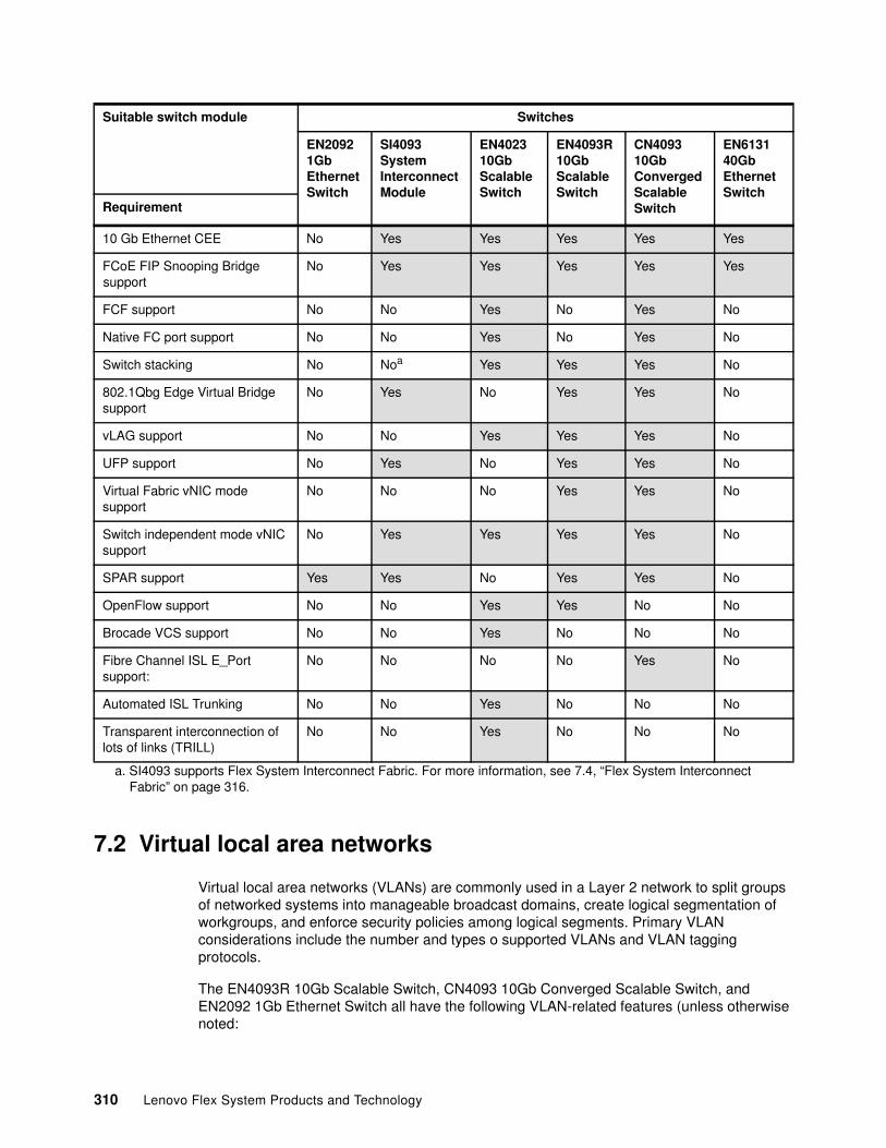
7.2 Virtual local area networks
Virtual local area networks (VLANs) are commonly used in a Layer 2 network to split groups of networked systems into manageable broadcast domains, create logical segmentation of workgroups, and enforce security policies among logical segments. Primary VLAN considerations include the number and types o supported VLANs and VLAN tagging protocols.
The EN4093R 10Gb Scalable Switch, CN4093 10Gb Converged Scalable Switch, and EN2092 1Gb Ethernet Switch all have the following VLAN-related features (unless otherwise noted:
10 Gb Ethernet CEE No Yes Yes Yes Yes Yes
FCoE FIP Snooping Bridge support
No Yes Yes Yes Yes Yes
FCF support No No Yes No Yes No
Native FC port support No No Yes No Yes No
Switch stacking No Noa Yes Yes Yes No
802.1Qbg Edge Virtual Bridge support
No Yes No Yes Yes No
vLAG support No No Yes Yes Yes No
UFP support No Yes No Yes Yes No
Virtual Fabric vNIC mode support
No No No Yes Yes No
Switch independent mode vNIC support
No Yes Yes Yes Yes No
SPAR support Yes Yes No Yes Yes No
OpenFlow support No No Yes Yes No No
Brocade VCS support No No Yes No No No
Fibre Channel ISL E_Port support:
No No No No Yes No
Automated ISL Trunking No No Yes No No No
Transparent interconnection of lots of links (TRILL)
No No Yes No No No
a. SI4093 supports Flex System Interconnect Fabric. For more information, see 7.4, “Flex System Interconnect Fabric” on page 316.
Suitable switch module Switches
EN2092 1Gb Ethernet Switch
SI4093 System Interconnect Module
EN4023 10Gb Scalable Switch
EN4093R 10Gb Scalable Switch
CN4093 10Gb Converged Scalable Switch
EN613140GbEthernet Switch
Requirement
310 Lenovo Flex System Products and Technology
� Support for 4094 active VLANs, out of the range of 1 - 4094
Some VLANs might be reserved when certain features (for example, stacking and UFP) are enabled.
� IEEE 802.1Q for VLAN tagging on links (also called trunking by some vendors)
Support for tagged or untagged native VLAN.
� Port-based VLANs
� Protocol-based VLANs
� Spanning Tree per VLAN (Per VLAN Rapid Spanning Tree)
This mode is the default Spanning Tree mode for the EN2092 1Gb Ethernet Switch, EN4093R 10Gb Scalable Switch, and CN4093 10Gb Converged Scalable Switch. The SI4093 System Interconnect Module does not support Spanning Tree.
Limited to 127 instances of Spanning Tree. VLANs added after 127 instances are operational and placed into Spanning Tree instance 1.
� 802.1x Guest VLANs
� VLAN Maps for ACLs
� VLAN-based port mirroring
The SI4093 System Interconnect Module by default is VLAN not apparent. It passes packets through the switch regardless of tagged or untagged so the number of VLANs that are supported is limited to whatever the compute node operating system and the upstream network support. When it is changed from its default mode to SPAR local domain mode, it supports up to 250 VLANs, but does not support Spanning Tree because it prohibits a user from creating a loop.
Specific to 802.1Q VLAN tagging, this feature is critical to maintain VLAN separation when packets in multiple VLANs must traverse a common link between devices. Without a tagging protocol, such as 802.1Q, maintaining VLAN separation between devices can be accomplished through a separate link for each VLAN, which is a less than optimal solution.
The need for 802.1Q VLAN tagging is not relegated to networking devices only. It is also supported and frequently used on end nodes and is implemented differently by various operating systems. For example, for Windows Server 2008 and earlier, a vendor driver was needed to subdivide the physical interface into logical NICs, with each logical NIC set for a specific VLAN. Typically, this setup is part of the teaming software from the NIC vendor. Windows Server 2012 has tagging option natively available.
For Linux, tagging is done by creating subinterfaces of a physical or logical NIC, such as eth0.10 for VLAN 10 on physical interface eth0.
Note: Under certain configurations (for example, Easy Connect mode), the EN4093R 10Gb Scalable Switch and CN4093 10Gb Converged Scalable Switch are not apparent to VLAN tags and act as a VLAN tag pass-through. For more information about Easy Connect, see 7.9, “Easy Connect concept” on page 336.
Tagging support: In rare cases, there are some older non-standards based tagging protocols that are used by vendors. These protocols are not compatible with 802.1Q or the Enterprise Chassis switching products.
Chapter 7. Network integration 311
For VMware ESX, tagging can be done within the vSwitch through port group tag settings (known as Virtual Switch Tagging). Tagging also can be done in the operating system within the guest VM (which is called Virtual Guest Tagging).
From an operating system perspective, having several logical interfaces can be useful when an application requires more than two separate interfaces and you do not want to dedicate an entire physical interface. It might also help to implement strict security policies for separating network traffic that uses VLANs and having access to server resources from different VLANs without adding more physical network adapters.
Review the documentation of the application to ensure that the application that is deployed on the system supports the use of logical interfaces that are often associated with VLAN tagging.
The Flex System EN4023 10Gb Scalable Switch is a Brocade VCS fabric technology switch module, that has the following Layer 2 switching features:
� Address Resolution Protocol (ARP) RFC 826� High availability/In-Service Software Upgrade; hardware-enabled� IGMP v1/v2 Snooping� MAC Learning and Aging� Link Aggregation Control Protocol (LACP) IEEE 802.3ad/802.1AX� VLANs� VLAN Encapsulation 802.1Q� Private VLANs� Edge loop detection (ELD)� Per-VLAN Spanning Tree (PVST+/PVRST+)� RSTP 802.1w� MSTP 802.1s� STP PortFast, BPDU Guard, BPDU Filter� STP Root Guard� Layer 2 ACLs� Pause Frames 802.3x� Uni-Directional Link Detection (UDLD)
As can be seem, unlike the SI4093 Systems Interconnect, the EN4023 10Gb Scalable Switch fully supports Spanning Tree and VLANs.
For more information about Ethernet switch modules that are available with the Enterprise Chassis, see 4.2, “I/O modules” on page 102.
7.3 Scalability and port flexibility
Many of the switches in the Flex System portfolio offer flexibility in how many ports you must pay for up front and which ports (internal or external) are enabled.
Scalable switches support a licensing method that is called Feature on-Demand (FoD). With FoD, if you do not need all of the internal and external ports that the switch provides. You also do not need to purchase them at the initial time of order. Instead, when you are ready to use the extra ports that a switch provides, you can enable them by purchasing and FoD license.
Scalable switches also support a method whereby you can specify which of the ports you licensed are enabled. For example, you might want to enable more internal ports and fewer external ports, or enable QSFP+ ports or Omni ports instead of standard 10 GbE ports. Depending on the switch, this feature is called flexible port mapping or Dynamic Port on-Demand.
312 Lenovo Flex System Products and Technology
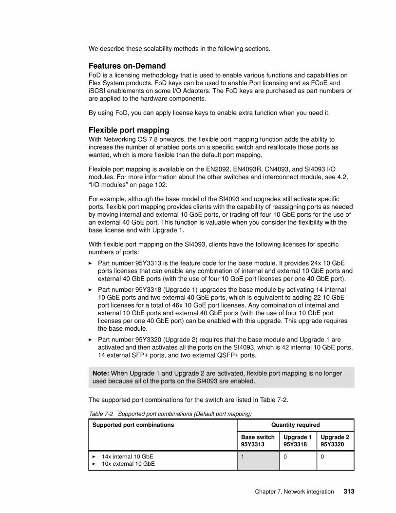
We describe these scalability methods in the following sections.
Features on-DemandFoD is a licensing methodology that is used to enable various functions and capabilities on Flex System products. FoD keys can be used to enable Port licensing and as FCoE and iSCSI enablements on some I/O Adapters. The FoD keys are purchased as part numbers or are applied to the hardware components.
By using FoD, you can apply license keys to enable extra function when you need it.
Flexible port mappingWith Networking OS 7.8 onwards, the flexible port mapping function adds the ability to increase the number of enabled ports on a specific switch and reallocate those ports as wanted, which is more flexible than the default port mapping.
Flexible port mapping is available on the EN2092, EN4093R, CN4093, and SI4093 I/O modules. For more information about the other switches and interconnect module, see 4.2, “I/O modules” on page 102.
For example, although the base model of the SI4093 and upgrades still activate specific ports, flexible port mapping provides clients with the capability of reassigning ports as needed by moving internal and external 10 GbE ports, or trading off four 10 GbE ports for the use of an external 40 GbE port. This function is valuable when you consider the flexibility with the base license and with Upgrade 1.
With flexible port mapping on the SI4093, clients have the following licenses for specific numbers of ports:
� Part number 95Y3313 is the feature code for the base module. It provides 24x 10 GbE ports licenses that can enable any combination of internal and external 10 GbE ports and external 40 GbE ports (with the use of four 10 GbE port licenses per one 40 GbE port).
� Part number 95Y3318 (Upgrade 1) upgrades the base module by activating 14 internal 10 GbE ports and two external 40 GbE ports, which is equivalent to adding 22 10 GbE port licenses for a total of 46x 10 GbE port licenses. Any combination of internal and external 10 GbE ports and external 40 GbE ports (with the use of four 10 GbE port licenses per one 40 GbE port) can be enabled with this upgrade. This upgrade requires the base module.
� Part number 95Y3320 (Upgrade 2) requires that the base module and Upgrade 1 are activated and then activates all the ports on the SI4093, which is 42 internal 10 GbE ports, 14 external SFP+ ports, and two external QSFP+ ports.
The supported port combinations for the switch are listed in Table 7-2.
Table 7-2 Supported port combinations (Default port mapping)
Note: When Upgrade 1 and Upgrade 2 are activated, flexible port mapping is no longer used because all of the ports on the SI4093 are enabled.
Supported port combinations Quantity required
Base switch95Y3313
Upgrade 195Y3318
Upgrade 295Y3320
� 14x internal 10 GbE� 10x external 10 GbE
1 0 0
Chapter 7. Network integration 313
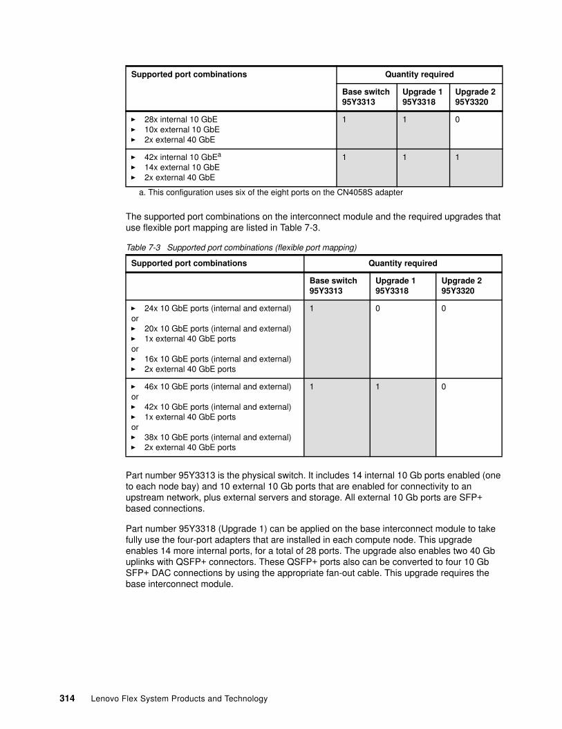
The supported port combinations on the interconnect module and the required upgrades that use flexible port mapping are listed in Table 7-3.
Table 7-3 Supported port combinations (flexible port mapping)
Part number 95Y3313 is the physical switch. It includes 14 internal 10 Gb ports enabled (one to each node bay) and 10 external 10 Gb ports that are enabled for connectivity to an upstream network, plus external servers and storage. All external 10 Gb ports are SFP+ based connections.
Part number 95Y3318 (Upgrade 1) can be applied on the base interconnect module to take fully use the four-port adapters that are installed in each compute node. This upgrade enables 14 more internal ports, for a total of 28 ports. The upgrade also enables two 40 Gb uplinks with QSFP+ connectors. These QSFP+ ports also can be converted to four 10 Gb SFP+ DAC connections by using the appropriate fan-out cable. This upgrade requires the base interconnect module.
� 28x internal 10 GbE� 10x external 10 GbE� 2x external 40 GbE
1 1 0
� 42x internal 10 GbEa
� 14x external 10 GbE� 2x external 40 GbE
1 1 1
a. This configuration uses six of the eight ports on the CN4058S adapter
Supported port combinations Quantity required
Base switch95Y3313
Upgrade 195Y3318
Upgrade 295Y3320
� 24x 10 GbE ports (internal and external)or� 20x 10 GbE ports (internal and external)� 1x external 40 GbE portsor� 16x 10 GbE ports (internal and external)� 2x external 40 GbE ports
1 0 0
� 46x 10 GbE ports (internal and external)or� 42x 10 GbE ports (internal and external)� 1x external 40 GbE portsor� 38x 10 GbE ports (internal and external)� 2x external 40 GbE ports
1 1 0
Supported port combinations Quantity required
Base switch95Y3313
Upgrade 195Y3318
Upgrade 295Y3320
314 Lenovo Flex System Products and Technology
Part number 95Y3320 (Upgrade 2) can be applied on top of Upgrade 1 when you want more uplink bandwidth on the interconnect module or if you want extra internal bandwidth to the compute nodes with the adapters that can support six ports (such as CN4058S). The upgrade enables the remaining four external 10 Gb uplinks with SFP+ connectors and 14 more internal 10 Gb ports for a total of 42 ports (three to each compute node).
When FoDs are applied to the SI4093 System Interconnect Module, they are done so by using the Switch Partitioning (SPAR) feature, which automatically puts each new set of ports that are added by the FoD process into their own grouping with no interaction with ports in other partitions. This configuration can be adjusted after the FoD is applied so that ports to be part of different or the same partitions, if wanted.
In summary, flexible port mapping can be used for the following functions:
� Ports can be enabled where they are needed (externally or internally), up to the maximum available total bandwidth licensed level.
� Flexible reassignment of ports: Internal to internal, external to external, and internal to external.
� OmniPorts on CN4093 can be exchanged for 10 G SFP+ ports.
� 4 x 10 Gb licenses can be assigned to QSFP+ port for 40 Gb uplinks.
For more information about each specific switch or interconnect module (including its licensing), see 4.2, “I/O modules” on page 102.
The ability to add ports and bandwidth as needed is a critical element of a scalable platform, such as the Flex System Enterprise Chassis.
Dynamic Ports on-DemandThe EN4023 10Gb Scalable Switch implements known as Dynamic Ports on-Demand (DPoD) which is similar to flexible port mapping found in other switches. With DPoD, ports are licensed as they come online to the switch; therefore, the EN4023 allows you to buy only the ports that you need when, you need them. The port enablements can be moved to other ports, if required.
The base module includes 24 port licenses for 10 GbE connectivity that can be applied to the internal and external ports. You then have the flexibility of turning on more 10 GbE ports and 40 GbE uplinks when you need them by using FoD licensing capabilities that provide “pay as you grow” scalability.
The EN4023 module is initially licensed for 24 ports (internal or external 10 GbE connectivity). Further ports can be activated, including 16 10 GbE ports and two 40 Gb external uplink ports with the FoD Upgrade 1 license option.
A total of 16 10 GbE ports are activated, with the FoD Upgrade 2 license option. Upgrade 1 and Upgrade 2 can be applied independently of each other.
Withdrawn: The EN4023 switch and its FoD upgrades are no longer available as they have now been withdrawn from marketing.
Chapter 7. Network integration 315
7.4 Flex System Interconnect Fabric
The Flex System Interconnect Fabric (FSIF) solution is an integration of Flex System components that provides a solid foundation of compute, network, storage, and software resources.
FSIF supports the following configurations as a highly integrated point of delivery (PoD) solution for data centers:
� Two G8264CS top of rack (ToR) switches
� Up to nine Flex System chassis that are populated with two SI4093 embedded switches in each chassis
� Up to 126 half-wide Flex System Compute Nodes with 2-port LOM or 4-port 10 Gb converged network adapters (CNAs)
� One or more external Lenovo Storwize V7000 storage systems
FSIF integrates an entire PoD into a seamless network fabric for server and storage under single IP management. It also attaches to the upstream data center network as a loop-free Layer 2 stub network fabric with a single Ethernet uplink connection or trunk group to each layer 2 network.
FSIF integrated PoD solution requires only network provisioning for uplink connections to data center network, downlink connections to server nodes, and storage connections to storage nodes.
The Interconnect Fabric solution features the following key elements:
� Hardware elements:
– CN4052S and CN4054S adapters– RackSwitch G8264CS (10/40 GbE, 4/8 Gb FC uplink) as Aggregation– SI4093 System Interconnect Module (10 GbE to server) as Access– Lenovo Storwize V7000
� Software elements:
– Single IP managed multi-rack cluster (hDFP)– Automated rolling (staggered) upgrades of individual switches– Per-server link redundancy (LAG or active/passive teaming)– Dynamic bandwidth within and out of the PoD– Multi-rack Flex System Interconnect mode– Integration of UFP and VMready
� Management elements:
– Switch Center Management application (fabric management)– Lenovo XClarity configuration patterns (compute node NIC configuration)
316 Lenovo Flex System Products and Technology
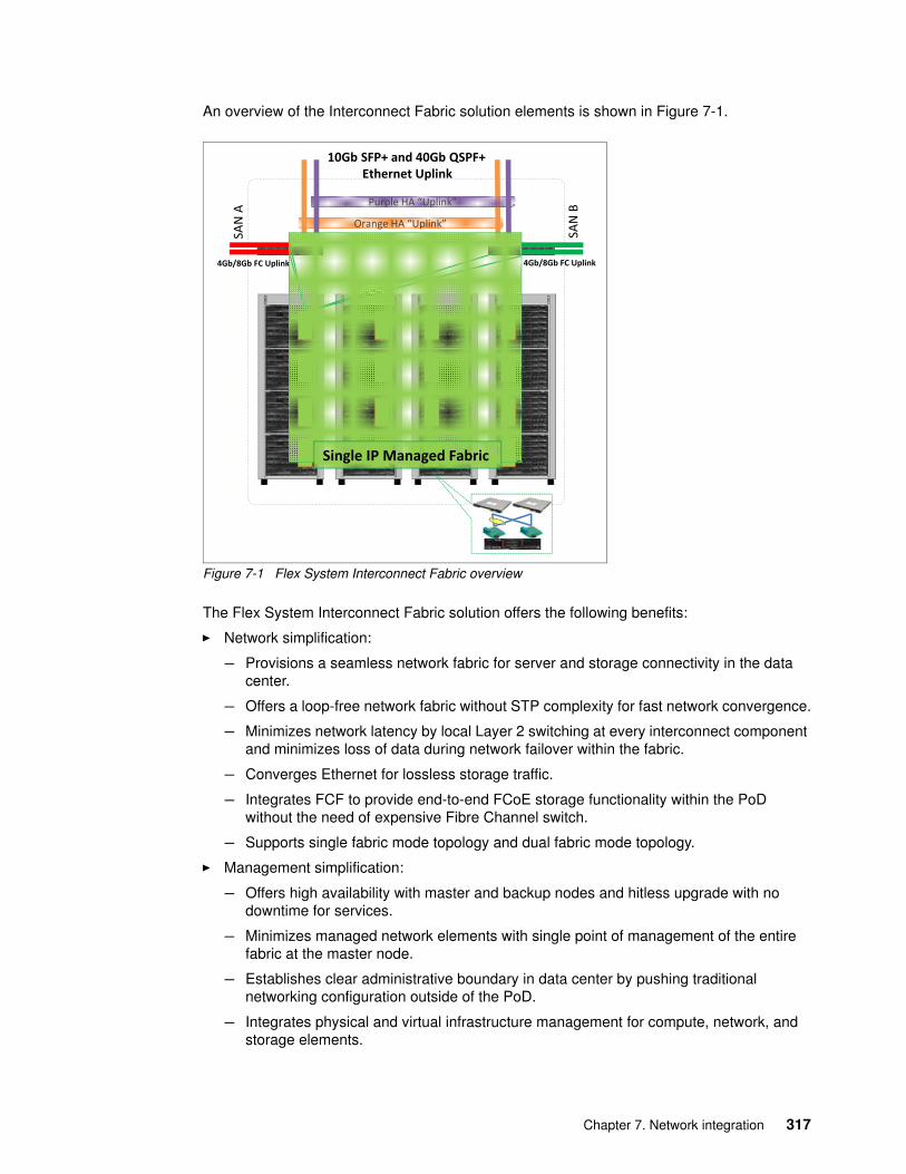
An overview of the Interconnect Fabric solution elements is shown in Figure 7-1.
Figure 7-1 Flex System Interconnect Fabric overview
The Flex System Interconnect Fabric solution offers the following benefits:
� Network simplification:
– Provisions a seamless network fabric for server and storage connectivity in the data center.
– Offers a loop-free network fabric without STP complexity for fast network convergence.
– Minimizes network latency by local Layer 2 switching at every interconnect component and minimizes loss of data during network failover within the fabric.
– Converges Ethernet for lossless storage traffic.
– Integrates FCF to provide end-to-end FCoE storage functionality within the PoD without the need of expensive Fibre Channel switch.
– Supports single fabric mode topology and dual fabric mode topology.
� Management simplification:
– Offers high availability with master and backup nodes and hitless upgrade with no downtime for services.
– Minimizes managed network elements with single point of management of the entire fabric at the master node.
– Establishes clear administrative boundary in data center by pushing traditional networking configuration outside of the PoD.
– Integrates physical and virtual infrastructure management for compute, network, and storage elements.
4Gb/8Gb FC Uplink
SAN
A
SAN
B
Orange HA �Uplink�
Purple HA �Uplink�
Single IP Managed Fabric
10Gb SFP+ and 40Gb QSPF+Ethernet Uplink
4Gb/8Gb FC Uplink
Chapter 7. Network integration 317
� Storage integration:
– Provides access to external SAN storage infrastructure, such as Lenovo Storwize V7000.
� Scalable PoD design:
– Enables the size of the PoD to grow without adding management complexity.
– Adds chassis resources up to the maximum configuration under single IP management of the PoD.
7.5 High Availability
Clients might require continuous access to their network-based resources and applications. Providing High Availability (HA) for client network-attached resources can be a complex task that involves fitting multiple pieces together on a hardware and software level. One key to system HA is to provide HA access to the network infrastructure.
Network infrastructure availability can be achieved by using certain techniques and technologies. Most techniques and technologies are widely used standards, but some are specific to the Enterprise Chassis. In this section, we review the most common technologies that can be implemented in an Enterprise Chassis environment to provide HA to the network infrastructure.
A typical LAN infrastructure consists of server network interface controllers (NICs), client NICs, and network devices, such as Ethernet switches and cables that connect them. Specific to the Enterprise Chassis, the potential failure areas for node network access include port failures (on switches and the node adapters), the midplane, and the I/O modules.
The first step in achieving HA is to provide physical redundancy of components that are connected to the infrastructure. Providing this redundancy typically means that the following measures are taken:
� Deploy node NICs in pairs.� Deploy switch modules in pairs.� Connect the pair of node NICs to separate I/O modules in the Enterprise Chassis.� Provide connections from each I/O module to a redundant upstream infrastructure.
318 Lenovo Flex System Products and Technology
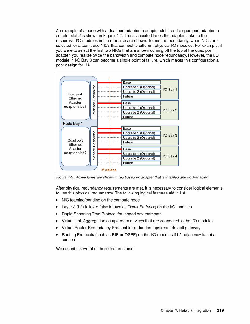
An example of a node with a dual port adapter in adapter slot 1 and a quad port adapter in adapter slot 2 is shown in Figure 7-2. The associated lanes the adapters take to the respective I/O modules in the rear also are shown. To ensure redundancy, when NICs are selected for a team, use NICs that connect to different physical I/O modules. For example, if you were to select the first two NICs that are shown coming off the top of the quad port adapter, you realize twice the bandwidth and compute node redundancy. However, the I/O module in I/O Bay 3 can become a single point of failure, which makes this configuration a poor design for HA.
Figure 7-2 Active lanes are shown in red based on adapter that is installed and FoD-enabled
After physical redundancy requirements are met, it is necessary to consider logical elements to use this physical redundancy. The following logical features aid in HA:
� NIC teaming/bonding on the compute node
� Layer 2 (L2) failover (also known as Trunk Failover) on the I/O modules
� Rapid Spanning Tree Protocol for looped environments
� Virtual Link Aggregation on upstream devices that are connected to the I/O modules
� Virtual Router Redundancy Protocol for redundant upstream default gateway
� Routing Protocols (such as RIP or OSPF) on the I/O modules if L2 adjacency is not a concern
We describe several of these features next.
Node Bay 1
Inte
rface
Con
nect
orI/O Bay 1
BaseUpgrade 1 (Optional)Upgrade 2 (Optional)Future
I/O Bay 2
BaseUpgrade 1 (Optional)Upgrade 2 (Optional)Future
Inte
rface
Con
nect
or
I/O Bay 3
BaseUpgrade 1 (Optional)Upgrade 2 (Optional)Future
I/O Bay 4
BaseUpgrade 1 (Optional)Upgrade 2 (Optional)Future
Midplane
Dual portEthernetAdapter
Adapter slot 1
Quad portEthernetAdapter
Adapter slot 2
Chapter 7. Network integration 319
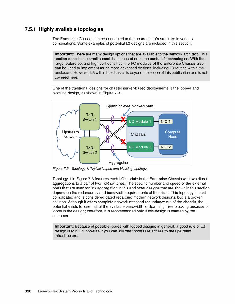
7.5.1 Highly available topologies
The Enterprise Chassis can be connected to the upstream infrastructure in various combinations. Some examples of potential L2 designs are included in this section.
One of the traditional designs for chassis server-based deployments is the looped and blocking design, as shown in Figure 7-3.
Figure 7-3 Topology 1: Typical looped and blocking topology
Topology 1 in Figure 7-3 features each I/O module in the Enterprise Chassis with two direct aggregations to a pair of two ToR switches. The specific number and speed of the external ports that are used for link aggregation in this and other designs that are shown in this section depend on the redundancy and bandwidth requirements of the client. This topology is a bit complicated and is considered dated regarding modern network designs, but is a proven solution. Although it offers complete network-attached redundancy out of the chassis, the potential exists to lose half of the available bandwidth to Spanning Tree blocking because of loops in the design; therefore, it is recommended only if this design is wanted by the customer.
Important: There are many design options that are available to the network architect. This section describes a small subset that is based on some useful L2 technologies. With the large feature set and high port densities, the I/O modules of the Enterprise Chassis also can be used to implement much more advanced designs, including L3 routing within the enclosure. However, L3 within the chassis is beyond the scope of this publication and is not covered here.
Important: Because of possible issues with looped designs in general, a good rule of L2 design is to build loop-free if you can still offer nodes HA access to the upstream infrastructure.
Chassis ComputeNode
NIC 1
NIC 2
UpstreamNetwork
ToRSwitch 2
ToRSwitch 1
Aggregation
X
X
Spanning-tree blocked path
I/O Module 1
I/O Module 2
320 Lenovo Flex System Products and Technology
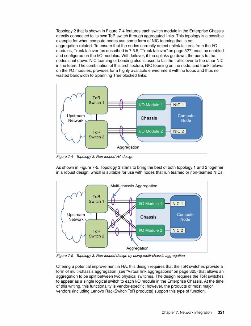
Topology 2 that is shown in Figure 7-4 features each switch module in the Enterprise Chassis directly connected to its own ToR switch through aggregated links. This topology is a possible example for when compute nodes use some form of NIC teaming that is not aggregation-related. To ensure that the nodes correctly detect uplink failures from the I/O modules, Trunk failover (as described in 7.5.5, “Trunk failover” on page 327) must be enabled and configured on the I/O modules. With failover, if the uplinks go down, the ports to the nodes shut down. NIC teaming or bonding also is used to fail the traffic over to the other NIC in the team. The combination of this architecture, NIC teaming on the node, and trunk failover on the I/O modules, provides for a highly available environment with no loops and thus no wasted bandwidth to Spanning Tree blocked links.
Figure 7-4 Topology 2: Non-looped HA design
As shown in Figure 7-5, Topology 3 starts to bring the best of both topology 1 and 2 together in a robust design, which is suitable for use with nodes that run teamed or non-teamed NICs.
Figure 7-5 Topology 3: Non-looped design by using multi-chassis aggregation
Offering a potential improvement in HA, this design requires that the ToR switches provide a form of multi-chassis aggregation (see “Virtual link aggregations” on page 325) that allows an aggregation to be split between two physical switches. The design requires the ToR switches to appear as a single logical switch to each I/O module in the Enterprise Chassis. At the time of this writing, this functionality is vendor-specific; however, the products of most major vendors (including Lenovo RackSwitch ToR products) support this type of function.
Chassis ComputeNode
NIC 1
NIC 2
UpstreamNetwork
ToRSwitch 2
ToRSwitch 1 I/O Module 1
I/O Module 2
Aggregation
Chassis ComputeNode
NIC 1
NIC 2
UpstreamNetwork
ToRSwitch 2
ToRSwitch 1
Multi-chassis Aggregation
I/O Module 1
I/O Module 2
Aggregation
Chapter 7. Network integration 321
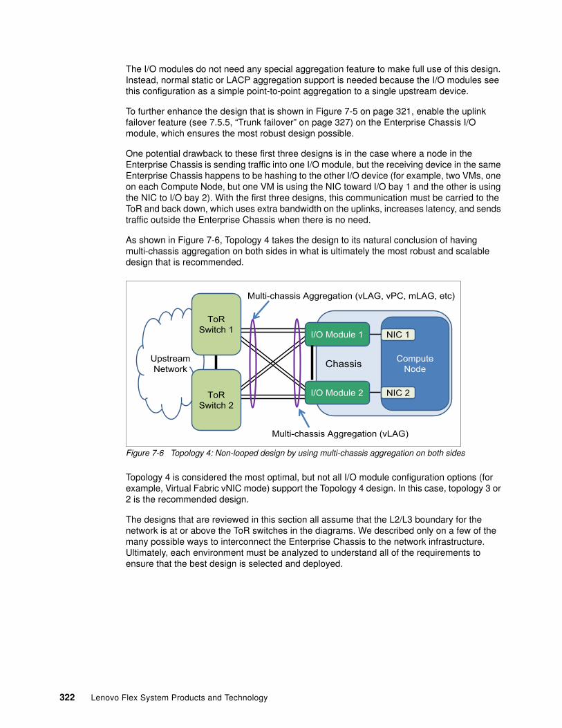
The I/O modules do not need any special aggregation feature to make full use of this design. Instead, normal static or LACP aggregation support is needed because the I/O modules see this configuration as a simple point-to-point aggregation to a single upstream device.
To further enhance the design that is shown in Figure 7-5 on page 321, enable the uplink failover feature (see 7.5.5, “Trunk failover” on page 327) on the Enterprise Chassis I/O module, which ensures the most robust design possible.
One potential drawback to these first three designs is in the case where a node in the Enterprise Chassis is sending traffic into one I/O module, but the receiving device in the same Enterprise Chassis happens to be hashing to the other I/O device (for example, two VMs, one on each Compute Node, but one VM is using the NIC toward I/O bay 1 and the other is using the NIC to I/O bay 2). With the first three designs, this communication must be carried to the ToR and back down, which uses extra bandwidth on the uplinks, increases latency, and sends traffic outside the Enterprise Chassis when there is no need.
As shown in Figure 7-6, Topology 4 takes the design to its natural conclusion of having multi-chassis aggregation on both sides in what is ultimately the most robust and scalable design that is recommended.
Figure 7-6 Topology 4: Non-looped design by using multi-chassis aggregation on both sides
Topology 4 is considered the most optimal, but not all I/O module configuration options (for example, Virtual Fabric vNIC mode) support the Topology 4 design. In this case, topology 3 or 2 is the recommended design.
The designs that are reviewed in this section all assume that the L2/L3 boundary for the network is at or above the ToR switches in the diagrams. We described only on a few of the many possible ways to interconnect the Enterprise Chassis to the network infrastructure. Ultimately, each environment must be analyzed to understand all of the requirements to ensure that the best design is selected and deployed.
Chassis ComputeNode
NIC 1
NIC 2
UpstreamNetwork
ToRSwitch 2
ToRSwitch 1
Multi-chassis Aggregation (vLAG, vPC, mLAG, etc)
I/O Module 1
I/O Module 2
Multi-chassis Aggregation (vLAG)
322 Lenovo Flex System Products and Technology
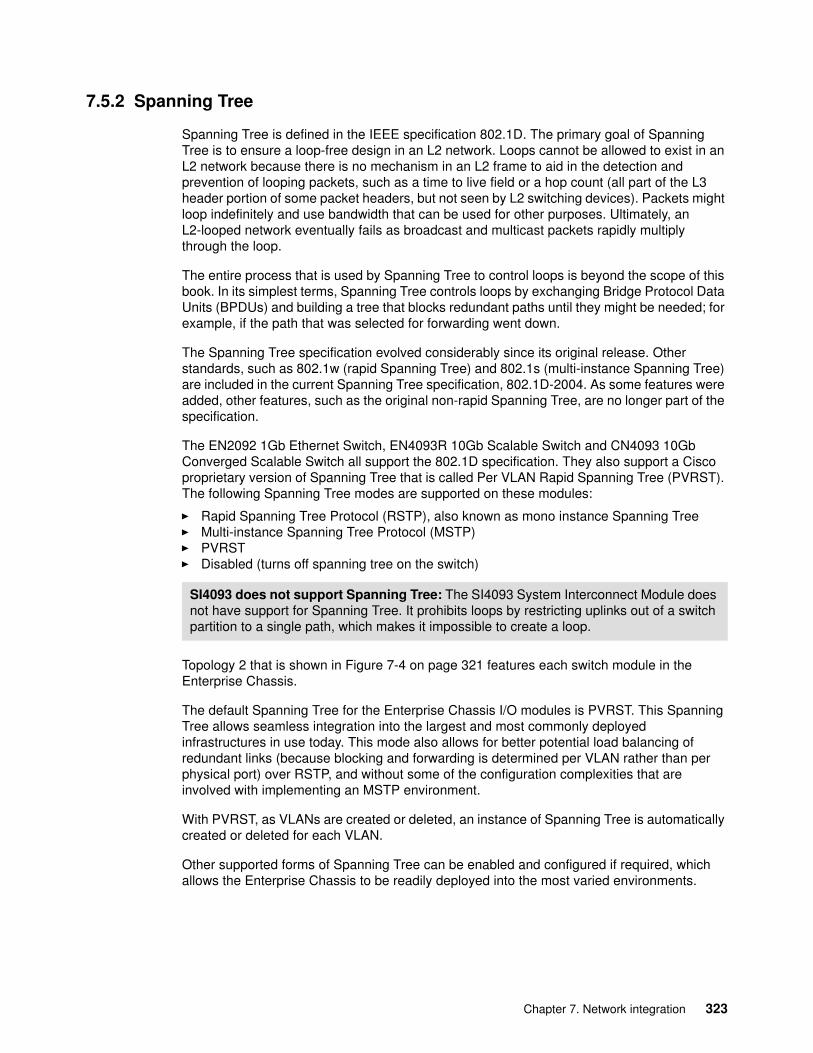
7.5.2 Spanning Tree
Spanning Tree is defined in the IEEE specification 802.1D. The primary goal of Spanning Tree is to ensure a loop-free design in an L2 network. Loops cannot be allowed to exist in an L2 network because there is no mechanism in an L2 frame to aid in the detection and prevention of looping packets, such as a time to live field or a hop count (all part of the L3 header portion of some packet headers, but not seen by L2 switching devices). Packets might loop indefinitely and use bandwidth that can be used for other purposes. Ultimately, an L2-looped network eventually fails as broadcast and multicast packets rapidly multiply through the loop.
The entire process that is used by Spanning Tree to control loops is beyond the scope of this book. In its simplest terms, Spanning Tree controls loops by exchanging Bridge Protocol Data Units (BPDUs) and building a tree that blocks redundant paths until they might be needed; for example, if the path that was selected for forwarding went down.
The Spanning Tree specification evolved considerably since its original release. Other standards, such as 802.1w (rapid Spanning Tree) and 802.1s (multi-instance Spanning Tree) are included in the current Spanning Tree specification, 802.1D-2004. As some features were added, other features, such as the original non-rapid Spanning Tree, are no longer part of the specification.
The EN2092 1Gb Ethernet Switch, EN4093R 10Gb Scalable Switch and CN4093 10Gb Converged Scalable Switch all support the 802.1D specification. They also support a Cisco proprietary version of Spanning Tree that is called Per VLAN Rapid Spanning Tree (PVRST). The following Spanning Tree modes are supported on these modules:
� Rapid Spanning Tree Protocol (RSTP), also known as mono instance Spanning Tree� Multi-instance Spanning Tree Protocol (MSTP)� PVRST� Disabled (turns off spanning tree on the switch)
Topology 2 that is shown in Figure 7-4 on page 321 features each switch module in the Enterprise Chassis.
The default Spanning Tree for the Enterprise Chassis I/O modules is PVRST. This Spanning Tree allows seamless integration into the largest and most commonly deployed infrastructures in use today. This mode also allows for better potential load balancing of redundant links (because blocking and forwarding is determined per VLAN rather than per physical port) over RSTP, and without some of the configuration complexities that are involved with implementing an MSTP environment.
With PVRST, as VLANs are created or deleted, an instance of Spanning Tree is automatically created or deleted for each VLAN.
Other supported forms of Spanning Tree can be enabled and configured if required, which allows the Enterprise Chassis to be readily deployed into the most varied environments.
SI4093 does not support Spanning Tree: The SI4093 System Interconnect Module does not have support for Spanning Tree. It prohibits loops by restricting uplinks out of a switch partition to a single path, which makes it impossible to create a loop.
Chapter 7. Network integration 323
7.5.3 Link aggregation
Sometimes referred to as trunking, port channel, or Etherchannel, link aggregation involves taking multiple physical links and binding them into a single common link for use between two devices. The primary purposes of aggregation are to improve HA and increase bandwidth.
Bundling the linksAlthough there are several different kinds of aggregation, the two most common and are supported by the Enterprise Chassis I/O modules are static and Link Aggregation Control Protocol (LACP).
Static aggregation does not use any protocol to create the aggregation. Instead, static aggregation combines the ports that are based on the aggregation configuration that is applied on the ports and assumes that the other side of the connection does the same.
LACP is an IEEE standard that was defined in 802.3ad. The standard was later included in the mainline 802.3 standard, but then was pulled out into the current standard 802.1AX-2008. LACP is a dynamic way of determining whether both sides of the link agree they should be aggregating.
The decision to use static or LACP is usually a question of what a client uses in their network. If there is no preference, the considerations that are described in this section can aid in the decision-making process.
Static aggregation is the quickest and easiest way to build an aggregated link. This method also is the most stable in high-bandwidth usage environments, particularly if pause frames are exchanged.
The use of static aggregation can be advantageous in mixed vendor environments because it can help prevent possible interoperability issues. Because settings in the LACP standard do not have a recommended default, vendors can use different defaults, which can lead to unexpected interoperation. For example, the LACP Data Unit (LACPDU) timers can be set to be exchanged every 1 second or every 30 seconds. If one side is set to 1 second and one side is set to 30 seconds, the LACP aggregation can be unstable. This problem is not an issue with static aggregations.
PAgP support: In rare cases, there are still some older, non-standards based aggregation protocols, such as Port Aggregation Protocol (PAgP) in use by some vendors. These protocols are not compatible with static or LACP aggregations.
Static LACP: In some cases, static aggregation is referred to as static LACP. This term is a contradictory term because it is difficult in this context to be static and have a Control Protocol.
Timers: Most vendors default to the use of the 30-second exchange of LACPDUs, including RackSwitch switches. If you encounter a vendor that defaults to 1-second timers (for example, Juniper), we advise that the other vendor changes to operate with 30-second timers rather than setting both to 1 second. This 30-second setting tends to produce a more robust aggregation as opposed to the 1-second timers.
324 Lenovo Flex System Products and Technology

One of the drawbacks to static aggregation is that it lacks a mechanism to detect if the other side is correctly configured for aggregation. Therefore, if one side is static and the other side is not configured, configured incorrectly, or is not connected to the correct ports, a network outage can occur by bringing up the links.
Based on the information that is presented in this section, if you are sure that your links are connected to the correct ports and that both sides are configured correctly for static aggregation, static aggregation is a solid choice.
LACP has the inherent safety that a protocol brings to this process. At link up, LACPDUs are exchanged and both sides must agree they are using LACP before it attempts to bundle the links. Therefore, in the case of mis-configuration or incorrect connections, LACP helps protect the network from an unplanned outage.
Lenovo switches also feature enhanced LACP to support a feature that is known as suspend-port. By definition of the IEEE standard, if ports cannot bundle because the other side does not understand LACP (for example, is not configured for LACP), the ports should be treated as individual ports and remain operational. This feature might lead to potential issues under certain circumstances (such as though Spanning Tree was disabled). To prevent accidental loops, the suspend-port feature can hold down the ports until proper LACPDUs are exchanged and the links can be bundled. This feature also protects against certain mis-cabling or mis-configuration that might split the aggregation into multiple smaller aggregations. For more information about this feature, see the Application Guide that is provided for the product.
The disadvantages of the use of LACP are that it takes a small amount of time to negotiate the aggregation and form an aggregating link (usually under a second), and it can become unstable and unexpectedly fail in environments with heavy and continued pause frame activity.
Another factor to consider about aggregation is whether it is better to aggregate multiple low-speed links into a high-speed aggregation, or use a single high-speed link with a similar speed to all of the links in the aggregation.
If your primary goal is HA, aggregations can offer a no-single-point-of-failure situation that a single high-speed link cannot offer.
If maximum performance and lowest possible latency are the primary goals, often a single high-speed link makes more sense. Another factor is cost. Often, one high-speed link can cost more to implement than a link that consists of an aggregation of multiple slower links.
Virtual link aggregationsAside from the standard point-to-point aggregations that are described in this section, there is a technology that provides multi-chassis aggregation, which is sometimes called distributed aggregation or virtual link aggregation.
Under the latest IEEE specifications, an aggregation is still defined as a bundle between only two devices. By this definition, you cannot create an aggregation on one device and have the links of that aggregation connect to more than a single device on the other side of the aggregation. The use of only two devices limits the ability to offer certain robust designs.
Chapter 7. Network integration 325
Although the standards bodies are working on a solution that provides split aggregations across devices, most vendors devised their own version of multi-chassis aggregation. For example, Cisco has virtual Port Channel (vPC) on Nexus products, and Virtual Switch System (VSS) on the 6500 line. Lenovo offers virtual Link Aggregation (vLAG) on many of its RackSwitch ToR solutions, and on the EN4093R 10Gb Scalable Switch and CN4093 10Gb Converged Scalable Switch.
The primary goals of virtual link aggregation are to overcome the limits that are imposed by current standards-based aggregation and provide a distributed aggregation across a pair of switches instead of a single switch.
The decisions whether to aggregate and which method of aggregation is most suitable to a specific environment are not always straightforward. However, if the decision is made to aggregate, the I/O modules for the Enterprise Chassis offer the necessary wanted features to integrate into the aggregated infrastructure.
7.5.4 NIC teaming
NIC teaming (which is also known as bonding) is a solution that is used on servers to logically bond two or more NICs to form one or more logical interfaces for purposes of HA, increased performance, or both. Although teaming or bonding is not a switch-based technology, it is a critical component of a highly available environment and is described here for reference purposes only.
There are many forms of NIC teaming, and the types that are available for a server are tied to the operating system that is installed on the server.
For Microsoft Windows, the teaming software traditionally was provided by the NIC vendor and was installed as an add-on to the operating system. This software often included the elements that are necessary to enable VLAN tagging on the logical NICs that were created by the teaming software. These logical NICs are seen by the operating system as physical NICs and are treated as such when they are configured. Depending on the NIC vendor, the teaming software might offer several different types of failover, including simple Active/Standby, static aggregation, dynamic aggregation (LACP), and vendor-specific load balancing schemes. Starting with Windows Server 2012, NIC teaming (along with VLAN tagging) is native to the operating system and no longer requires a third-party application.
For Linux based systems, the bonding module is used to implement NIC teaming. Various bonding modes are available, most commonly mode 1 (Active/Standby) and mode 4 (LACP aggregation). As with Windows teaming, Linux bonding also offers logical interfaces to the operating system that can be used as wanted. Unlike Windows teaming, VLAN tagging is controlled by different software in Linux and can create subinterfaces for VLANs off physical and logical entities; for example, eth0.10 for VLAN 10 on physical eth0, or bond0:20, for VLAN 20 on a logical NIC bond pair 0.
Another common server operating system, VMware ESX, also has built-in teaming in the form of assigning multiple NICs to a common vSwitch (a logical switch that runs within an ESX host, which is shared by the VMs that require network access). VMware has several teaming modes, with the default option called Route that is based on the originating virtual port ID. This default mode provides a per VM load balance of physical NICs that are assigned to the vSwitch and does not require any form of aggregation that is configured on the upstream switches. Another mode, Route based on IP hash, equates to a static aggregation. If configured, it requires the upstream switch connections to be configured for static aggregation.
326 Lenovo Flex System Products and Technology
The teaming method that is best for a specific environment is unique to each situation. However, the following common elements might help in the decision-making process:
� Do not select a mode that requires some form of aggregation (static/LACP) on the switch side unless the NICs in the team go to the same physical switch or logical switch that was created by a technology, such as virtual link aggregation or stacking.
� If a mode that uses some form of aggregation is used, you must also perform proper configuration on the upstream switches to complete the aggregation on that side.
� The most stable solution is often Active/Standby, but this solution has the disadvantage of losing any bandwidth on a NIC that is in standby mode.
� Most teaming software also offers proprietary forms of load balancing. The selection of these modes must be thoroughly tested for suitability to the task for an environment.
� Most teaming software incorporates the concept of auto failback, which means that if a NIC went down and then came back up, it automatically fails back to the original NIC. Although this function helps ensure good load balancing, each time that a NIC fails, some small packet loss might occur, which can lead to unexpected instabilities. When a flapping link occurs, a severe disruption to the network connection of the servers results as the connection path goes back and forth between NICs. One way to mitigate this situation is to disable the auto failback feature. After an NIC fails, the traffic falls back only if the original link is restored and something happened to the current link that requires a switchover.
It is your responsibility to understand your goals and the tools that are available to achieve those goals. NIC teaming is one tool for users that need HA connections for their compute nodes.
7.5.5 Trunk failover
Trunk failover, which is also known as failover or link state tracking, is an important feature for ensuring HA in chassis-based computing. This feature is used with NIC teaming to ensure the compute nodes can detect an uplink failure from the I/O modules.
With traditional NIC teaming and bonding, the decision process that is used by the teaming software to use an NIC is based on whether the link to the NIC is up or down. In a chassis-based environment, the link between the NIC and the internal I/O module rarely goes down unexpectedly. Instead, a more common occurrence might be the uplinks from the I/O module go down; for example, an upstream switch crashed or cables were disconnected. In this situation, although the I/O module no longer has a path to send packets because of the upstream fault, the actual link to the internal server NIC is still up. The server might continue to send traffic to this unusable I/O module, which leads to a black hole condition.
To prevent this black hole condition and to ensure continued connection to the upstream network, trunk failover can be configured on the I/O modules. Depending on the configuration, trunk failover monitors a set of uplinks. If these uplinks go down, trunk failover takes down the configured server-facing links. This action alerts the server that this path is not available, and NIC teaming can take over and redirect traffic to the other NIC.
Trunk failover offers the following features:
� In addition to triggering on link up/down, trunk failover operates on the Spanning Tree blocking and discarding state. From a data packet perspective, a blocked link is no better than a down link.
� Trunk failover can be configured to fail over if the number of links in a monitored aggregation falls below a certain number.
� Trunk failover can be configured to trigger on VLAN failure.
Chapter 7. Network integration 327
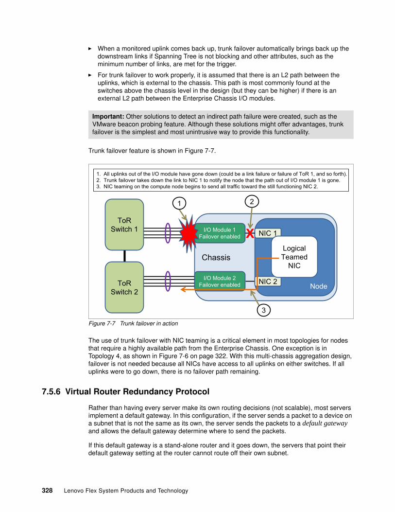
� When a monitored uplink comes back up, trunk failover automatically brings back up the downstream links if Spanning Tree is not blocking and other attributes, such as the minimum number of links, are met for the trigger.
� For trunk failover to work properly, it is assumed that there is an L2 path between the uplinks, which is external to the chassis. This path is most commonly found at the switches above the chassis level in the design (but they can be higher) if there is an external L2 path between the Enterprise Chassis I/O modules.
Trunk failover feature is shown in Figure 7-7.
Figure 7-7 Trunk failover in action
The use of trunk failover with NIC teaming is a critical element in most topologies for nodes that require a highly available path from the Enterprise Chassis. One exception is in Topology 4, as shown in Figure 7-6 on page 322. With this multi-chassis aggregation design, failover is not needed because all NICs have access to all uplinks on either switches. If all uplinks were to go down, there is no failover path remaining.
7.5.6 Virtual Router Redundancy Protocol
Rather than having every server make its own routing decisions (not scalable), most servers implement a default gateway. In this configuration, if the server sends a packet to a device on a subnet that is not the same as its own, the server sends the packets to a default gateway and allows the default gateway determine where to send the packets.
If this default gateway is a stand-alone router and it goes down, the servers that point their default gateway setting at the router cannot route off their own subnet.
Important: Other solutions to detect an indirect path failure were created, such as the VMware beacon probing feature. Although these solutions might offer advantages, trunk failover is the simplest and most unintrusive way to provide this functionality.
0� ����7��&)<,��7'��;�'(���$=����7���(�>��/�)�����)����7���������&)<�;�&�7������;�&�7����;�?�@�9��)��,��;��'(!0�0� ?�7)<�;�&��>���'�<�,����)�'(���&)<�'�������'��)�'&;:�'(��)����'(�'�'(����'(��7'��;��$=����7����&,�/�)�0�0� ����'���&)/��)�'(������7'��)������/&),�'��,�)������'��;;&��'������'(��,'&���;7)�'&�)&)/������0
�(�,,&,
����
����
�����?�@�%�&'�(��
?�@�%�&'�(� �$=�"��7���
-�&��>����)�����
�$=�"��7����-�&��>����)�����
X*�/&����?���������
�
�
328 Lenovo Flex System Products and Technology
To prevent this type of single point of failure, most data center routers that offer a default gateway service implement a redundancy protocol so that one router can take over for the other when one router fails.
Although there are nonstandard solutions to this issue (for example, Hot Standby Router Protocol [HSRP]), most routers now implement standards-based Virtual Router Redundancy Protocol (VRRP).
In its simplest form, two routers that run VRRP share a common IP address (which is called the Virtual IP address). One router traditionally acts as master and the other as a backup if the master goes down. Information is constantly exchanged between the routers to ensure one can provide the services of the default gateway to the devices that point at its Virtual IP address. Servers that require a default gateway service point the default gateway service at the Virtual IP address, and redundancy is provided by the pair of routers that run VRRP.
The EN2092 1Gb Ethernet Switch, EN4093R 10Gb Scalable Switch, and CN4093 10Gb Converged Scalable Switch offer support for VRRP directly within the Enterprise Chassis, but most common data center designs place this function in the routing devices above the chassis (or even higher). The design depends on how important it to have a common L2 network between nodes in different chassis. If needed, this function can be moved within the Enterprise Chassis as networking requirements dictate.
7.6 FCoE capabilities
One common way to reduce management points and networking elements in an environment is by converging technologies that were traditionally implemented on separate physical infrastructures. As with collapsing office phone systems from a separate cabling plant and components into a common IP infrastructure, Fibre Channel networks also are experiencing this type of convergence. And as with phone systems that moved to Ethernet, Fibre Channel also is moving to Ethernet.
Fibre Channel over Ethernet (FCoE) removes the need for separate host bus adapters (HBAs) on the servers and separate Fibre Channel cables out of the back of the server or chassis. Instead, a Converged Network Adapter (CNA) is installed in the server. The CNA presents what appears to be an NIC and an HBA to the operating system, but the output from the server is only 10 Gb Ethernet.
The Flex System Enterprise Chassis provides multiple I/O modules that support FCoE. The EN4093R 10Gb Scalable Switch, CN4093 10Gb Converged Scalable Switch, SI4093 System Interconnect Module, and EN4023 10Gb Scalable Switch all support FCoE. The CN4093 10Gb Converged Scalable Switch and EN4023 10Gb Scalable Switch also supporting the Fibre Channel Forwarder (FCF) function. The CN4093 10Gb Converged Scalable Switch supports NPV, full fabric Fibre Channel, and native Fibre Channel ports.
This FCoE function also requires the correct components on the Compute Nodes in the form of the proper CNA and licensing. No special license is needed on any of the I/O modules to support FCoE because support is included as part of the base product.
The EN4091 10Gb Ethernet Pass-thru also can provide support for FCoE, assuming that the proper CNA and license are on the Compute Node and the upstream connection supports FCoE traffic.
Important: Although they offer similar services, HSRP and VRRP are not compatible with each other.
Chapter 7. Network integration 329
The EN4093R 10Gb Scalable Switch and SI4093 System Interconnect Module are FIP Snooping Bridges (FSB). They provide FCoE transit services between the Compute Node and an upstream FCF device. A typical design requires an upstream device, such as an RackSwitch G8264CS switch that breaks the Fibre Channel portion of the FCoE out to the necessary Fibre Channel format.
The CN4093 10Gb Converged Scalable Switch also can act as an FSB, but if wanted, it can operate as an FCF, which allows the switch to support a full fabric mode for direct storage attachment, or in N Port Virtualizer (NPV) mode, for connection to a non Lenovo SAN fabric. The CN4093 10Gb Converged Scalable Switch also supports native Fibre Channel ports for directly connecting Fibre Channel devices to the CN4093 10Gb Converged Scalable Switch.
Because the Enterprise Chassis also supports native Fibre Channel modules and various FCoE technologies, it can provide a storage connection solution that meets any wanted goal regarding remote storage access.
7.7 vNIC solution capabilities
Virtual Network Interface Controller (vNIC) is a way to divide a physical NIC into smaller logical NICs (or partition them) so that the operating system has more ways to logically connect to the infrastructure. The vNIC feature is supported only on 10 Gb ports that are facing the compute nodes within the chassis, and only on the certain Ethernet I/O modules., including the EN4093R 10Gb Scalable Switch and CN4093 10Gb Converged Scalable Switch. vNIC also requires a node adapter that also supports this functionality.
There are two primary forms of vNIC available: Virtual Fabric mode (or Switch dependent mode) and Switch independent mode. The Virtual Fabric mode is subdivided into two submodes: dedicated uplink vNIC mode and shared uplink vNIC mode.
Both vNIC modes share the following elements:
� They are supported only on 10 Gb connections.
� Each vNIC mode allows an NIC to be divided into four vNICs per physical NIC (can be less than four, but not more).
� They all require an adapter that has support for one or more of the vNIC modes.
� When vNICs are created, the default bandwidth is 2.5 Gb for each vNIC, but can be configured to be anywhere from 100 Mb up to the full bandwidth of the NIC.
� The bandwidth of all configured vNICs on a physical NIC cannot exceed 10 Gb.
� Both modes support FCoE.
Important: In its default mode, the SI4093 System Interconnect Module supports passing the FCoE traffic up to the FCF, but no FSB support. If FIP snooping is required on the SI4093 System Interconnect Module, it must be placed into local domain SPAR mode.
Note: For more information about Unified Fabric Port, see 7.8, “Unified Fabric Port feature” on page 334.
330 Lenovo Flex System Products and Technology
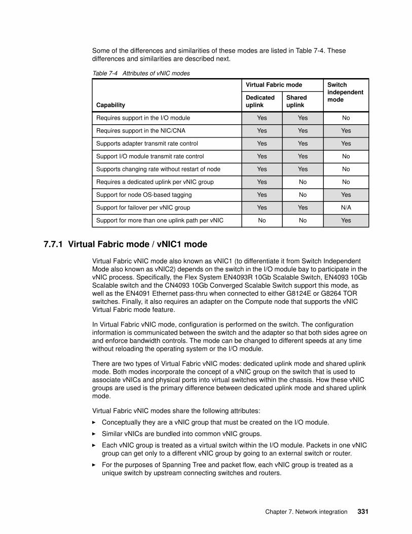
Some of the differences and similarities of these modes are listed in Table 7-4. These differences and similarities are described next.
Table 7-4 Attributes of vNIC modes
7.7.1 Virtual Fabric mode / vNIC1 mode
Virtual Fabric vNIC mode also known as vNIC1 (to differentiate it from Switch Independent Mode also known as vNIC2) depends on the switch in the I/O module bay to participate in the vNIC process. Specifically, the Flex System EN4093R 10Gb Scalable Switch, EN4093 10Gb Scalable switch and the CN4093 10Gb Converged Scalable Switch support this mode, as well as the EN4091 Ethernet pass-thru when connected to either G8124E or G8264 TOR switches. Finally, it also requires an adapter on the Compute node that supports the vNIC Virtual Fabric mode feature.
In Virtual Fabric vNIC mode, configuration is performed on the switch. The configuration information is communicated between the switch and the adapter so that both sides agree on and enforce bandwidth controls. The mode can be changed to different speeds at any time without reloading the operating system or the I/O module.
There are two types of Virtual Fabric vNIC modes: dedicated uplink mode and shared uplink mode. Both modes incorporate the concept of a vNIC group on the switch that is used to associate vNICs and physical ports into virtual switches within the chassis. How these vNIC groups are used is the primary difference between dedicated uplink mode and shared uplink mode.
Virtual Fabric vNIC modes share the following attributes:
� Conceptually they are a vNIC group that must be created on the I/O module.
� Similar vNICs are bundled into common vNIC groups.
� Each vNIC group is treated as a virtual switch within the I/O module. Packets in one vNIC group can get only to a different vNIC group by going to an external switch or router.
� For the purposes of Spanning Tree and packet flow, each vNIC group is treated as a unique switch by upstream connecting switches and routers.
Capability
Virtual Fabric mode Switch independent modeDedicated
uplinkShared uplink
Requires support in the I/O module Yes Yes No
Requires support in the NIC/CNA Yes Yes Yes
Supports adapter transmit rate control Yes Yes Yes
Support I/O module transmit rate control Yes Yes No
Supports changing rate without restart of node Yes Yes No
Requires a dedicated uplink per vNIC group Yes No No
Support for node OS-based tagging Yes No Yes
Support for failover per vNIC group Yes Yes N/A
Support for more than one uplink path per vNIC No No Yes
Chapter 7. Network integration 331
� Both modes support the addition of physical NICs (pNIC) (the NICs from nodes not using vNIC) to vNIC groups for internal communication to other pNICs and vNICs in that vNIC group, and share any uplink that is associated with that vNIC group.
Dedicated uplink modeDedicated uplink mode is the default mode when vNIC is enabled on the I/O module. In dedicated uplink mode, each vNIC group must have its own dedicated physical or logical (aggregation) uplink. In this mode, no more than one physical or logical uplink to a vNIC group can be assigned and it assumed that HA is achieved by some combination of aggregation on the uplink or NIC teaming on the server.
In dedicated uplink mode, vNIC groups are VLAN-independent to the nodes and the rest of the network, which means that you do not need to create VLANs for each VLAN that is used by the nodes. The vNIC group takes each packet (tagged or untagged) and moves it through the switch.
This mode is accomplished by the use of a form of Q-in-Q tagging. Each vNIC group is assigned some VLAN that is unique to each vNIC group. Any packet (tagged or untagged) that comes in on a downstream or upstream port in that vNIC group has a tag that is placed on it that is equal to the vNIC group VLAN. As that packet leaves the vNIC into the node or out an uplink, that tag is removed and the original tag (or no tag, depending on the original packet) is revealed.
Shared uplink modeShared uplink mode is a global option that can be enabled on an I/O module that has the vNIC feature enabled. As the name suggests, it allows an uplink to be shared by more than one group, which reduces the possible number of uplinks that are required.
It also changes the way that the vNIC groups process packets for tagging. In shared uplink mode, it is expected that the servers no longer use tags. Instead, the vNIC group VLAN acts as the tag that is placed on the packet. When a server sends a packet into the vNIC group, it has a tag that is placed on it equal to the vNIC group VLAN and then sends it out the uplink that is tagged with that VLAN.
332 Lenovo Flex System Products and Technology
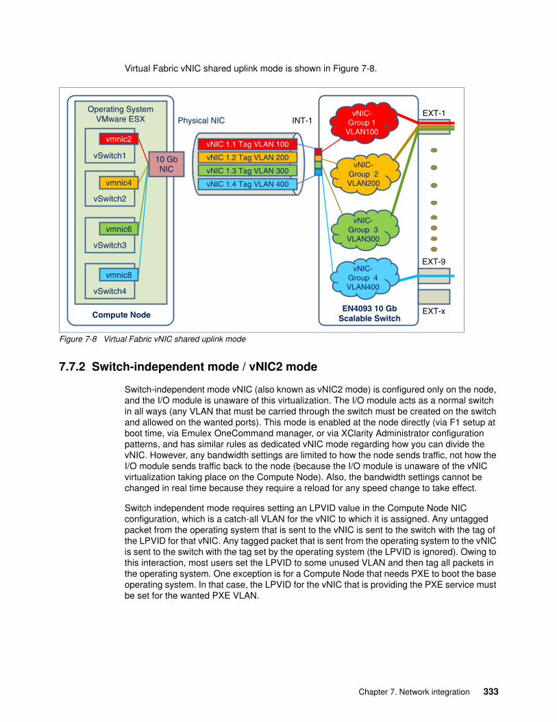
Virtual Fabric vNIC shared uplink mode is shown in Figure 7-8.
Figure 7-8 Virtual Fabric vNIC shared uplink mode
7.7.2 Switch-independent mode / vNIC2 mode
Switch-independent mode vNIC (also known as vNIC2 mode) is configured only on the node, and the I/O module is unaware of this virtualization. The I/O module acts as a normal switch in all ways (any VLAN that must be carried through the switch must be created on the switch and allowed on the wanted ports). This mode is enabled at the node directly (via F1 setup at boot time, via Emulex OneCommand manager, or via XClarity Administrator configuration patterns, and has similar rules as dedicated vNIC mode regarding how you can divide the vNIC. However, any bandwidth settings are limited to how the node sends traffic, not how the I/O module sends traffic back to the node (because the I/O module is unaware of the vNIC virtualization taking place on the Compute Node). Also, the bandwidth settings cannot be changed in real time because they require a reload for any speed change to take effect.
Switch independent mode requires setting an LPVID value in the Compute Node NIC configuration, which is a catch-all VLAN for the vNIC to which it is assigned. Any untagged packet from the operating system that is sent to the vNIC is sent to the switch with the tag of the LPVID for that vNIC. Any tagged packet that is sent from the operating system to the vNIC is sent to the switch with the tag set by the operating system (the LPVID is ignored). Owing to this interaction, most users set the LPVID to some unused VLAN and then tag all packets in the operating system. One exception is for a Compute Node that needs PXE to boot the base operating system. In that case, the LPVID for the vNIC that is providing the PXE service must be set for the wanted PXE VLAN.
Operating SystemVMware ESX Physical NIC
EXT-1
vSwitch1
vSwitch2
vSwitch3
vSwitch4
Compute Node
INT-1
EN4093 10 Gb Scalable Switch
EXT-9
EXT-x
vNIC 1.1 Tag VLAN 100
vNIC 1.2 Tag VLAN 200
vNIC 1.3 Tag VLAN 300
vNIC 1.4 Tag VLAN 400
vmnic8
vmnic6
vmnic4
vmnic2
10 Gb NIC
vNIC-Group 1
VLAN100
vNIC-Group 2VLAN200
vNIC-Group 3VLAN300
vNIC-Group 4VLAN400
Chapter 7. Network integration 333
Because all packets that are coming into the switch from an NIC that was configured for switch independent mode, vNICs always are tagged (by the operating system or by the LPVID setting if the operating system is not tagging). All VLANs that are allowed on the port on the switch side also should be tagging. Set the PVID/Native VLAN on the switch port to some unused VLAN, or set it to one that is used and enable PVID tagging to ensure that the port sends and receives PVID/Native VLAN packets as tagged.
In most operating systems, switch independent mode vNIC supports as many VLANs as the operating system supports. One exception is with bare metal Windows operating system installations, where in switch independent mode, only a limited number of VLANs are supported per vNIC (maximum of 63 VLANs, but less in some cases, depending on version of Windows and what driver is in use). For more information about any limitations for Windows and switch independent mode vNIC, see the documentation for your NIC.
In this section, we described the various modes of vNIC. The mode that is best-suited for a user depends on the user’s requirements. Virtual Fabric dedicated uplink mode offers the most control. Shared uplink mode and switch-independent mode offer the most flexibility with uplink connectivity.
7.8 Unified Fabric Port feature
Unified Fabric Port (UFP) is another approach to NIC virtualization (similar to vNIC but with enhanced flexibility) and should be considered the direction for future development in the virtual NIC area for Lenovo switching solutions.
UFP is supported on the following I/O modules with switch firmware 8.3 or later:
� SI4093 System Interconnect Module� EN4093R 10Gb Scalable Switch� CN4093 10Gb Converged Scalable Switch� EN4091 10Gb Ethernet pass-thru with TOR RackSwitch G8124E or G8264
UFP is supported on the following I/O adapters:
� CN4022 2-port 10Gb Converged Adapter� EN4172 2-port 10Gb Ethernet Adapter� CN4054 10Gb Virtual Fabric Adapters� CN4054R 10Gb Virtual Fabric Adapters� CN4058S 8-port 10Gb Virtual Fabric Adapter� CN4052 2-port 10Gb Virtual Fabric Adapter� CN4052S 10Gb Virtual Fabric Adapter� CN4054S 10Gb Virtual Fabric Adapter
UFP and vNIC are mutually exclusive in that you cannot enable UFP and vNIC at the same time on the same switch.
If a comparison were to be made between UFP and vNIC, UFP is most closely related to vNIC Virtual Fabric mode in that both sides, the switch, and the NIC/CNA share in controlling bandwidth usage. However, there are significant differences. Compared to vNIC, UFP supports the following modes of operation per virtual NIC (vPort):
� Access: The vPort allows only the default VLAN, which is similar to a physical port in access mode.
Note: 1Gb adapters do not support vNIC and UFP.
334 Lenovo Flex System Products and Technology
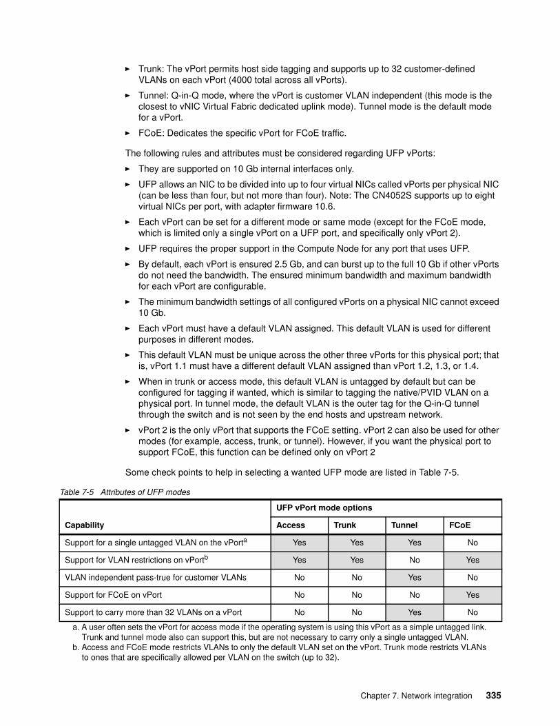
� Trunk: The vPort permits host side tagging and supports up to 32 customer-defined VLANs on each vPort (4000 total across all vPorts).
� Tunnel: Q-in-Q mode, where the vPort is customer VLAN independent (this mode is the closest to vNIC Virtual Fabric dedicated uplink mode). Tunnel mode is the default mode for a vPort.
� FCoE: Dedicates the specific vPort for FCoE traffic.
The following rules and attributes must be considered regarding UFP vPorts:
� They are supported on 10 Gb internal interfaces only.
� UFP allows an NIC to be divided into up to four virtual NICs called vPorts per physical NIC (can be less than four, but not more than four). Note: The CN4052S supports up to eight virtual NICs per port, with adapter firmware 10.6.
� Each vPort can be set for a different mode or same mode (except for the FCoE mode, which is limited only a single vPort on a UFP port, and specifically only vPort 2).
� UFP requires the proper support in the Compute Node for any port that uses UFP.
� By default, each vPort is ensured 2.5 Gb, and can burst up to the full 10 Gb if other vPorts do not need the bandwidth. The ensured minimum bandwidth and maximum bandwidth for each vPort are configurable.
� The minimum bandwidth settings of all configured vPorts on a physical NIC cannot exceed 10 Gb.
� Each vPort must have a default VLAN assigned. This default VLAN is used for different purposes in different modes.
� This default VLAN must be unique across the other three vPorts for this physical port; that is, vPort 1.1 must have a different default VLAN assigned than vPort 1.2, 1.3, or 1.4.
� When in trunk or access mode, this default VLAN is untagged by default but can be configured for tagging if wanted, which is similar to tagging the native/PVID VLAN on a physical port. In tunnel mode, the default VLAN is the outer tag for the Q-in-Q tunnel through the switch and is not seen by the end hosts and upstream network.
� vPort 2 is the only vPort that supports the FCoE setting. vPort 2 can also be used for other modes (for example, access, trunk, or tunnel). However, if you want the physical port to support FCoE, this function can be defined only on vPort 2
Some check points to help in selecting a wanted UFP mode are listed in Table 7-5.
Table 7-5 Attributes of UFP modes
Capability
UFP vPort mode options
Access Trunk Tunnel FCoE
Support for a single untagged VLAN on the vPorta
a. A user often sets the vPort for access mode if the operating system is using this vPort as a simple untagged link. Trunk and tunnel mode also can support this, but are not necessary to carry only a single untagged VLAN.
Yes Yes Yes No
Support for VLAN restrictions on vPortb
b. Access and FCoE mode restricts VLANs to only the default VLAN set on the vPort. Trunk mode restricts VLANs to ones that are specifically allowed per VLAN on the switch (up to 32).
Yes Yes No Yes
VLAN independent pass-true for customer VLANs No No Yes No
Support for FCoE on vPort No No No Yes
Support to carry more than 32 VLANs on a vPort No No Yes No
Chapter 7. Network integration 335
What are some of the criteria to decide whether a UFP or vNIC solution should be implemented to provide the virtual NIC capability?
In an environment that has not standardized on any specific virtual NIC technology and does not need per logical NIC failover today, UFP is the best choice. All future virtual NIC development is on UFP, and the per-logical NIC failover function is available in a future release. UFP has the advantage emulating vNIC virtual fabric mode (via tunnel mode for dedicate uplink vNIC and access mode for shared uplink vNIC) but can also offer virtual NIC support with customer VLAN awareness (trunk mode) and shared virtual group uplinks for access and trunk mode vPorts.
If an environment that is standardized on Virtual Fabric vNIC mode and plans to stay with it or requires the ability of failover per logical group today, Virtual Fabric vNIC mode is recommended.
Switch independent mode vNIC is exclusive of this decision-making process. Switch independent mode has its own unique attributes, one being truly switch independent, which allows you to configure the switch without restrictions to the virtual NIC technology other than allowing the proper VLANs. UFP and Virtual Fabric vNIC mode each have several unique switch-side requirements and configurations. The drawback to Switch independent mode vNIC is the inability to make changes without reloading the server, and the lack of bidirectional bandwidth allocation.
7.9 Easy Connect concept
The Easy Connect concept (which is sometimes called Easy Connect mode) is not necessarily a specific feature, but a way of using several different features to attempt to minimize ongoing switch management requirements. Some customers want the potential uplink cable reduction or increased Compute Node facing ports that are offered by a switch-based solution, but prefer the ease of use of a pass-through based solution to reduce the potential increase to management that is required for each new edge switch. The Easy Connect concept offers this reduction in management in a fully scalable switch-based solution.
There are several features that can be used to accomplish an Easy Connect solution. We describe a few of those features here. Easy Connect takes a switch module and makes it not apparent to the upstream network and the Compute Nodes. It accomplishes this feat by pre-creating a large aggregation of the uplinks (so there is no chance for loops), disabling Spanning Tree (so the upstream does not receive any Spanning Tree BPDUs), and then using a form of Q-in-Q to mask user VLAN tagging as the packets travel through the switch (to remove the need to configure each VLAN the Compute Nodes might need).
After it is configured, a switch in Easy Connect mode does not require any configuration changes as a customer adds and removes VLANs. Easy Connect turns the switch into a VLAN independent port aggregator, with support for growing up to the maximum bandwidth of the product (for example, add upgrade FoDs to increase the 10G links to Compute Nodes and number and types of uplinks that are available for connection to the upstream network).
UFP support: UFP is supported on SI4093, EN4093, EN4093R, CN4093 and EN4091 pass-thru when combined with upstream switches G8124E and G8264.
336 Lenovo Flex System Products and Technology
To configure an Easy Connect mode, customers have the following options:
� For customers that want an Easy Connect type of solution ready for use (zero touch switch deployment), the SI4093 System Interconnect Module provides this solution by default. The SI4093 System Interconnect Module accomplishes this feat by having the following factory default configuration:
– Putting all default internal and external ports into a single SPAR
– Putting all uplinks into a common LACP aggregation and enabling the LACP suspend-port feature
– Enabling the failover feature on the common LACP key
– No Spanning Tree support (the SI4093 is designed to never permit more than a single uplink path per SPAR so it does not support Spanning Tree)
� For customers that want the option of using advanced features but also want an Easy Connect mode solution, the EN4093R 10Gb Scalable Switch and CN4093 10Gb Converged Scalable Switch offer configurable options that can make them appear not apparent to the attaching Compute Nodes and upstream network switches, with the option of changing to more advanced modes of configuration when wanted.
The SI4093 System Interconnect Module accomplishes the easy connect function by defaulting to the SPAR feature in pass-through mode that puts all Compute Node ports and all uplinks into a common Q-in-Q group and transparently moves any user packets (tagged or untagged) between the Compute nodes and the upstream networking.
For the EN4093R 10Gb Scalable Switch and CN4093 10Gb Converged Scalable Switch, there are several features that can be used to accomplish Easy Connect. The primary difference between these switches and the SI4093 System Interconnect Module is that on these models, you must first perform a small set of configuration steps to set up this not apparent mode after which managing the switches is no longer required.
One common element of all Easy Connect modes is the use of a Q-in-Q type operation to hide user VLANs from the switch fabric in the I/O module, so that the switch acts as more of a port aggregator and is user VLAN independent. This configuration can be achieved by using any of the following features:
� The tagpvid-ingress option� vNIC Virtual Fabric dedicated uplink mode � UFP vPort tunnel mode� SPAR pass-through domain
All features can provide this Easy Connect functionality, with each having some pros and cons. For example, if you want to use Easy Connect with vLAG, you use the tagpvid-ingress mode (the other modes do not permit the vLAG ISL). However, if you want to use Easy Connect with FCoE today, you cannot use tagpvid-ingress and must switch to something else, such as the vNIC Virtual Fabric dedicated uplink mode or UFP tunnel mode (SPAR pass-through mode allows FCoE but does not support FIP snooping, which might be a concern for some customers).
Chapter 7. Network integration 337
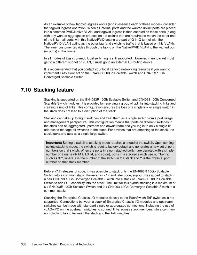
As an example of how tagpvid-ingress works (and in essence each of these modes), consider the tagpvid-ingress operation. When all internal ports and the wanted uplink ports are placed into a common PVID/Native VLAN, and tagpvid-ingress is then enabled on these ports (along with any wanted aggregation protocol on the uplinks that are required to match the other end of the links), all ports with this Native/PVID setting are part of Q-in-Q tunnel with the Native/PVID VLAN acting as the outer tag (and switching traffic that is based on this VLAN). The inner customer tag rides through the fabric on the Native/PVID VLAN to the wanted port (or ports) in this tunnel.
In all modes of Easy connect, local switching is still supported. However, if any packet must get to a different subnet or VLAN, it must go to an external L3 routing device.
It is recommended that you contact your local Lenovo networking resource if you want to implement Easy Connect on the EN4093R 10Gb Scalable Switch and CN4093 10Gb Converged Scalable Switch.
7.10 Stacking feature
Stacking is supported on the EN4093R 10Gb Scalable Switch and CN4093 10Gb Converged Scalable Switch modules. It is provided by reserving a group of uplinks into stacking links and creating a ring of links. This configuration ensures the loss of a single link or single switch in the stack does not lead to a disruption of the stack.
Stacking can take up to eight switches and treat them as a single switch from a port usage and management perspective. This configuration means that ports on different switches in the stack can be aggregated upstream and downstream and you log in to only a single IP address to manage all switches in the stack. For devices that are attaching to the stack, the stack looks and acts as a single large switch.
Before v7.7 releases of code, it was possible to stack only the EN4093R 10Gb Scalable Switch into a common stack. However, in v7.7 and later code, support was added to stack in a pair CN4093 10Gb Converged Scalable Switch into a stack of EN4093R 10Gb Scalable Switch to add FCF capability into the stack. The limit for this hybrid stacking is a maximum of 6 x EN4093R 10Gb Scalable Switch and 2 x CN4093 10Gb Converged Scalable Switch in a common stack.
Stacking the Enterprise Chassis I/O modules directly to the RackSwitch ToR switches is not supported. Connections between a stack of Enterprise Chassis I/O modules and upstream switches can be made with standard single or aggregated connections, including the use of vLAG/vPC on the upstream switches to connect links across stack members into a common non-blocking fabric between the stack and the ToR switches.
Important: Setting a switch to stacking mode requires a reload of the switch. Upon coming up into stacking mode, the switch is reset to factory default and generates a new set of port numbers on that switch. When the ports in a non-stacked switch are denoted with a simple number or a name (INTA1, EXT4, and so on), ports in a stacked switch use numbering such as X:Y, where X is the number of the switch in the stack and Y is the physical port number on that stack member.
338 Lenovo Flex System Products and Technology
An example of four I/O modules in a highly available stacking design is shown in Figure 7-9.
Figure 7-9 Virtual Fabric vNIC shared uplink mode
This example shows a design with no single points of failures via a stack of four I/O modules in a single stack.
One limitation of the current implementation of stacking is that if code must be upgraded, the entire stack must be reloaded. Because upgrades are uncommon and should be scheduled for non-production hours, a single stack design is efficient and clean. However, some customers do not want to have any downtime (scheduled or otherwise), so this single stack design is unwanted. For users that still want to use stacking, a two-stack design might be an option because a set of switches is stacked in bay 1 into one stack and a set of switches in bay 2 in a second stack.
The primary advantage to a two-stack design is that each stack can be upgraded one at a time, with the running stack maintaining connectivity for the Compute Nodes during the upgrade or reload. The down side is that traffic on one stack that must get to switches and the other stack must go through the upstream network.
Stacking might not be suitable for all customers. However, if you want to use it, it is another tool that is available for building a robust infrastructure by using the Enterprise Chassis I/O modules.
Staggered upgrade in stacking was added in release 8.2. During Staggered upgrade, a delay is added between member switch resets. The Staggered-upgrade “delay” parameter is added to the staggered-upgrade command to configure a delay between 1 to 20 minutes with a default of 1 minute
Multi-chassis Aggregation (vLAG, vPC, mLAG, etc)
Chassis 1 ComputeNode
NIC 1
NIC 2
UpstreamNetwork
ToRSwitch 2
ToRSwitch 1
I/O Module 1
I/O Module 2
Stacking
Chassis 2 ComputeNode
NIC 1
NIC 2
I/O Module 1
I/O Module 2
Chapter 7. Network integration 339
7.11 OpenFlow support
As of v7.7 code, the EN4093R 10Gb Scalable Switch supports an OpenFlow option. OpenFlow is an open standards-based approach for network switching that separates networking into the local data plane (on the switch) and a control plane that is external to the network switch (usually on a server). Instead of the use of normal learning mechanisms to build up tables of where packets must go, a switch that is running OpenFlow has the decision-making process in the external server. That server tells the switch to establish “flows” for the sessions that must traverse the switch.
The initial release of support for OpenFlow on the EN4093R 10Gb Scalable Switch is based on the OpenFlow 1.3.1 standard and supports the following modes of operation:
� Switch/Hybrid mode
Defaults to all ports as normal switch ports, but can be enabled for OpenFlow Hybrid mode without a reload such that some ports can then be enabled for OpenFlow while others still run normal switching.
� Dedicated OpenFlow mode
Requires a reload to go into effect. All ports on the switch are OpenFlow ports.
By default, the switch is a normal network switch that can be dynamically enabled for OpenFlow. In this default mode, you can issue a simple operational command to put the switch into Hybrid mode and start to configure ports as OpenFlow or normal switch ports. Inside the switch, ports that are configured into OpenFlow mode are isolated from ports in normal mode. Any communications between these OpenFlow and normal ports must occur outside of the switch.
Hybrid mode OpenFlow is suitable for users who want to experiment with OpenFlow on some ports while still use the other ports for regular switch traffic. Dedicated OpenFlow mode is for a customer who plans to run the entire switch in OpenFlow mode. It also has the benefit of allowing a user to ensure the number of a certain type of flows, which are known as FDB flows (hybrid mode does not). Lenovo also offers an OpenFlow controller to manage ports in OpenFlow mode.
In release 8.2, Openflow 1.3.1 group support was added and actions associated with flow entries can direct packets to a group. Also added was the ability to configure multiple Openflow static LAG ports and physical ports as edge ports. Release 8.2 also added sFlow support that provides sampling support for packets received on Openflow ports that are configured for sFlow.
For more information about configuring OpenFlow on the EN4093R 10Gb Scalable Switch, see the appropriate Application Guide for the product.
For more information about OpenFlow, see this website:
https://www.opennetworking.org/
7.12 802.1Qbg Edge Virtual Bridge support
The 802.1Qbg standard, which is also known as Edge Virtual Bridging (EVB) and Virtual Ethernet Port Aggregation (VEPA), is an IEEE standard that is targeted at bringing better network visibility and control into virtualized server environments. It accomplishes this feat by moving the control of packet flows between VMs up from the virtual switch in the hypervisor into the attaching physical switch, which allows the physical switch to provide granular control
340 Lenovo Flex System Products and Technology
to the flows between VMs. It also supports the virtualization of the physical NICs into virtual NICs via protocols that are part of the 802.1Qbg specification.
The 802.1Qbg standard is supported on the EN4093R 10Gb Scalable Switch and CN4093 10Gb Converged Scalable Switch modules.
The Lenovo implementation of 802.1Qbg supports the following features:
� Virtual Ethernet Bridging (VEB) and VEPA
Provides support for switching between VMs on a common hypervisor.
� Edge Control Protocol (ECP)
Provides reliable delivery of upper layer protocol data units (PDUs).
� Virtual Station Interface (VSI) Discovery and Configuration Protocol (VDP)
Provides support for advertising VSIs to the network and centralized configuration of policies for the VM, regardless of its location in the network.
� EVB Type-Length Value (TLV)
A component of Link layer Discover Protocol (LLDP) that is used to aid in the discovery and configuration of VEPA, ECP, and VDP.
� Configured with Edge Virtual Bridging (EVB), UFP supports up to 256 VLANs on a vPort
The current Lenovo implementation for these products is based on the 802.1Qbg draft, which has some variations from the final standard. For more information about Lenovo’s implementation and operation of 802.1Qbg, see the appropriate Application Guide for the switch.
For more information about this standard, see the IEEE documents that are available at this website:
http://standards.ieee.org/about/get/802/802.1.html
7.13 SPAR feature
SPAR is a feature that allows a physical switch to be carved into multiple logical switches. After it is carved up, ports within a SPAR session can talk only to each other. Ports that do not belong to a specific SPAR cannot communicate to ports in that SPAR without going outside of the switch.
As of this writing, the EN4093R 10Gb Scalable Switch, CN4093 10Gb Converged Scalable Switch, and SI4093 System Interconnect Module support SPAR.
SPAR includes the following primary modes of operation:
� Pass-through domain mode:
– This mode is the default mode when SPAR is enabled.
– It is VLAN-independent. It passes tagged and untagged packets through the SPAR session without looking at the customer tag.
– On the SI4093 System Interconnect Module, SPAR supports passing FCoE packets to upstream FCF, but without the benefit of FIP snooping within the SPAR. The EN4093R 10Gb Scalable Switch and CN4093 10Gb Converged Scalable Switch do not support FCoE traffic in Pass-Through domain mode as of this writing.
Chapter 7. Network integration 341
� Local domain mode:
– This mode is not VLAN-independent and requires a user to create any wanted VLANs on the switch.
– As of this writing, there is a limit of 256 VLANs in Local domain mode.
– Provides support for FIP Snooping on FCoE sessions.
– Unlike Pass-Through domain mode, Local domain mode provides strict control of end host VLAN usage.
The following points should be considered regarding SPAR:
� SPAR is disabled by default on the EN4093R 10Gb Scalable Switch and CN4093 10Gb Converged Scalable Switch. SPAR is enabled by default on SI4093 System Interconnect Module, with all ports defaulting to a single pass-through SPAR group. This configuration can be changed, if wanted.
� Any port can be a member only of a single SPAR group at one time.
� Only a single uplink path is allowed per SPAR group (it can be a single link, a static aggregation, or an LACP aggregation). This limitation ensures that no loops are possible with ports in a SPAR group.
� As of this writing, SPAR cannot be used with UFP or Virtual Fabric vNIC. Switch independent mode vNIC is supported by SPAR. UFP support is slated for a future release.
� As of this writing, up to eight SPAR sessions per switch are supported. This number might be increased in a future release.
SPAR must be considered as another tool in the user toolkit for ways to deploy the Enterprise Chassis Ethernet switching solutions in unique ways.
7.14 Management
Management of I/O modules in a Flex System chassis can be performed from a variety of methods, from command line to graphical user interfaces.
The various user interfaces that are available for the I/O modules (whether the CLI or the web-based GUI) offer the ability to fully configure and manage all features that are available to the switches. Some elements of the modules can be configured from the Chassis Management Module (CMM) user interface.
Any third-party management platforms that support SNMP also can be used to configure and manage the modules.
With Lenovo XClarity Administrator, Flex System switches are discovered and managed automatically when you manage the chassis that contains them. You cannot discover and managed Flex System switches independent of a chassis.
Lenovo XClarity Administrator can either be installed on a virtual machine running on a physical node inside the chassis, or can be installed externally on a Lenovo server.
Management of switches from within XClarity Administrator offers the following function and capabilities:
� View the status of all switches that Lenovo XClarity Administrator manages.
� View detailed information about a managed switch from Lenovo XClarity Administrator, including the firmware levels and IP addresses.
342 Lenovo Flex System Products and Technology
� Power on and off and restart a Flex System or RackSwitch switch from Lenovo XClarity Administrator.
� Launch the switch management interface from Lenovo XClarity Administrator.
� Launch a remote SSH session for a managed RackSwitch or Flex switch from Lenovo XClarity Administrator. (From the remote SSH session, you can use the command-line interface to perform management tasks that are not provided by Lenovo XClarity Administrator.)
� Modify the system properties for a specific Flex System or RackSwitch switch.
Ethernet I/O modules also can be managed by the command-line interface (CLI), web interface, or any third-party SNMP-based management tool.
The best tool for a user often depends on that user’s experience with different interfaces and their knowledge of networking features. Most commonly, the CLI is used by those users who work with networks as part of their daily jobs. The CLI offers the quickest way to accomplish tasks, such as scripting an entire configuration. The drawback to the CLI is that it tends to be more cryptic to those users that do not use them every day. For those users that do not need the power of the CLI, the web-based GUI permits the configuration and management of all switch features.
The EN4093R 10Gb Scalable Switch, CN4093 10Gb Converged Scalable Switch, and EN2092 1Gb Ethernet Switch modules all offer two CLI options (the pass-through module does not have a user interface because it is a non-managed device). The default CLI for these Ethernet switch modules is the Networking OS CLI, which is a menu-driven interface. A user also can enable an optional CLI known as industry standard CLI (isCLI) that more closely resembles Cisco IOS CLI. The SI4093 System Interconnect Module supports only the isCLI option for CLI access.
For more information about how to configure various features and the operation of the various user interfaces, see the Flex System information center for detailed user guides:
http://flexsystem.lenovofiles.com/help/index.jsp
The latest firmware is available for download from the support site, which also contains a change history file for each release, detailing enhancements, changes, and fixes. The Lenovo Support website is located at the following web address:
https://datacentersupport.lenovo.com/
7.15 Summary and conclusions
The Flex System platform provides a unique set of features that enable the integration of leading-edge technologies and transformation approaches into the data centers. These Flex System features ensure that the availability, performance, scalability, security, and manageability goals of the data center networking design are met as efficiently as possible.
The key data center technology implementation trends include the virtualization of servers, storage, and networks. Trends also include the steps toward infrastructure convergence that are based on mature 10 Gb Ethernet technology. In addition, the data center network is being flattened, and the logical overlay network becomes important in overall network design. These approaches and directions are fully supported by Flex System offerings.
With a full range of offerings from Lenovo and other leading vendors, networking solutions can be designed around the latest technologies.
Chapter 7. Network integration 343
Flex System data center networking capabilities provide the following solutions to many issues that arise in data centers where new technologies and approaches are being adopted:
� After 10 Gb Ethernet networks reach their maturity and price attractiveness, they can provide sufficient bandwidth for virtual machines in virtualized server environments and become a foundation of unified converged infrastructure. Flex System offers 10 Gb Ethernet Scalable Switches and Pass-through modules that can be used to build a unified converged fabric.
� Although 10 Gb Ethernet is becoming a prevalent server network connectivity technology, there is a need to go beyond 10 Gb to avoid oversubscription in switch-to-switch connectivity, which frees room for emerging technologies, such as 40 Gb Ethernet. Flex System offers the industry’s first 40 Gb Ethernet-capable switch, EN4093, to ensure that the sufficient bandwidth is available for inter-switch links.
� Network infrastructure must be VM-aware to ensure the end-to-end QoS and security policy enforcement. Flex System network switches offer VMready capability that provides VM visibility to the network and ensures that the network policies are implemented and enforced end-to-end.
� Pay-as-you-grow scalability becomes an essential approach as increasing network bandwidth demands must be satisfied in a cost-efficient way with no disruption in network services. Flex System offers scalable switches that enable ports when required by purchasing and activating simple software FoD upgrades without the need to buy and install more hardware.
� Infrastructure management integration becomes more important because the interrelations between appliances and functions are difficult to control and manage. Without integrated tools that simplify the data center operations, managing the infrastructure box-by-box becomes cumbersome. Flex System offers centralized systems management with Lenovo XClarity Administrator, that integrates network management functions into a common data center management framework with a single point of management.
344 Lenovo Flex System Products and Technology
Chapter 8. Storage integration
Flex System offers several possibilities for integration into storage infrastructures, such as Fibre Channel (FC), iSCSI, and Converged Enhanced Ethernet. This chapter describes important considerations to take into account during storage infrastructure planning. These considerations include storage system interoperability, I/O module selection and interoperability rules, performance, High Availability (HA) and redundancy, backup, and boot from storage area network (SAN). This chapter covers external storage.
This chapter includes the following topics:
� 8.1, “External storage” on page 346� 8.2, “Software defined storage” on page 354� 8.3, “Fibre Channel” on page 356� 8.4, “FCoE” on page 360� 8.5, “iSCSI” on page 361� 8.6, “HA and redundancy” on page 362� 8.7, “Performance” on page 363� 8.8, “Backup solutions” on page 363� 8.9, “Boot from SAN” on page 366
8
© Copyright Lenovo 2018. All rights reserved. 345
8.1 External storage
The following options are available for attaching external storage systems to Enterprise Chassis:
� SANs that are based on FC technologies� SANs that are based on iSCSI (x86 modes only)� Converged Networks that are based on 10 Gb Converged Enhanced Ethernet (CEE)
Traditionally, FC-based SANs are the most common and advanced design of external storage infrastructure. They provide high levels of performance, availability, redundancy, and scalability. However, the cost of implementing FC SANs is higher when compared with CEE or iSCSI. Almost every FC SAN includes the following major components:
� Host bus adapters (HBAs)� FC switches� FC storage servers � FC tape devices � Optical cables for connecting these devices to each other
iSCSI-based SANs provide all of the benefits of centralized shared storage in terms of storage consolidation and adequate levels of performance. However, they use traditional IP-based Ethernet networks instead of expensive optical cabling. iSCSI SANs consist of the following components:
� Server hardware iSCSI adapters or software iSCSI initiators
� Traditional network components, such as switches and routers
� Storage servers with an iSCSI interface, such as Lenovo Storage S2200 or S3200
Converged Networks can carry SAN and LAN types of traffic over the same physical infrastructure. You can use consolidation to decrease costs and increase efficiency in building, maintaining, operating, and managing the networking infrastructure.
iSCSI, FC-based SANs, and Converged Networks can be used for diskless solutions to provide greater levels of usage, availability, and cost effectiveness.
The following storage systems are supported connected to the Flex System Chassis and are described in this section:
� 8.1.1, “Lenovo ThinkSystem DS2200” on page 346� 8.1.2, “Lenovo ThinkSystem DS4200” on page 348� 8.1.3, “Lenovo ThinkSystem DS6200” on page 349� 8.1.4, “IBM Storwize V3700” on page 350� 8.1.5, “IBM Storwize V7000 Storage System from Lenovo” on page 351� 8.1.6, “Lenovo Storage V5030” on page 352� 8.1.7, “Lenovo Storage V3700 V2 and V3700 V2 XP” on page 353
For links to various interoperability documents, see Lenovo Storage Interoperability Links:
https://lenovopress.com/lp0584
8.1.1 Lenovo ThinkSystem DS2200
Designed with small-to-medium businesses and remote/branch offices in mind, the Lenovo ThinkSystem DS2200 SAN array offers enterprise-class features at entry-level pricing, along with 99.999 percent availability and is powered by a Rapid Data Placement Engine to accomplish this.
346 Lenovo Flex System Products and Technology
The easy-to-use management interface makes complex administrative storage tasks simple, including setup with the Rapid Deployment Wizard, in less than 15 minutes. The same interface is used across the DS Series family, allowing for flexible IT administration.
The ThinkSystem DS2200 offers connectivity choices and impressive storage capacities. Choose between 12Gb SAS, 8/16Gb Fibre Channel (FC), or 1/10Gb iSCSI to integrate into your existing network.
The DS2200 can hold up to 12x 3.5-inch or 24x 2.5-inch HDDs and SSDs internally, and supports up to 96 drives total (using three expansion units). The DS2200 also supports mixing LFF and SFF enclosures in the same array, providing the flexibility you need.
As your business grows, consider upgrading to the ThinkSystem DS4200 or DS6200 for higher performance, additional fabric support, more ports, and more expansion units. No data migration, reestablishing LUNs, or changing licenses is needed with this upgrade.
Features include:
� Low-cost, entry-level storage with dual active/active controller configurations for high availability and performance.
� Flexible host connectivity to match diverse client needs with support for 12 Gb SAS (SAS controller module) or 1/10 Gb iSCSI or 4/8/16 Gb Fibre Channel connectivity (FC/iSCSI controller module).
� 12 Gb SAS drive-side connectivity with support for 12x 3.5-inch large form factor (LFF) or 24x 2.5-inch small form factor (SFF) drives in the controller enclosure; scalable up to 48 LFF drives per system with the attachment of ThinkSystem DS Series LFF expansion units (12x LFF drives each) or up to 96 SFF drives per system with the attachment of ThinkSystem DS Series SFF expansion units (24x SFF drives each) to satisfy growing needs for storage capacity and performance.
� Flexibility in storing data on high-performance SAS SSDs, performance-optimized enterprise SAS HDDs, or capacity-optimized enterprise NL SAS HDDs; mixing and matching drive types and form factors within a single system to perfectly meet performance and capacity requirements for various workloads.
� Support for self-encrypting drives (SEDs) to allow clients to secure their sensitive data and to comply with various security regulations, when required.
� Rich set of standard functions available at no extra cost, including virtualized storage pools, snapshots, thin provisioning, rapid RAID rebuild, real-time HDD tiering, SSD read cache, and All Flash Array (AFA).
� Optional licensed functions, including higher number of snapshots for more scalability, real-time SSD tiering for boosting IOPS performance, and asynchronous replication for 24x7 data protection.
� Enhanced streaming performance for video surveillance and media/entertainment applications.
� Intuitive, web-based GUI for easy system set up and management, as well as Command Line Interface (CLI).
� EZ Start configuration wizard to quickly provision storage by creating storage pools, allocating storage space, and mapping hosts in just a few simple steps.
� Designed for 99.999% availability.
For more information about the Lenovo ThinkSystem DS2200 storage array, see the product guide, available from:
https://lenovopress.com/lp0509
Chapter 8. Storage integration 347
The DS2200 is supported connected to a Flex System Chassis. See the Interoperability matrix for details:
https://download.lenovo.com/storage/lenovo_storage_ds2200_4200_6200_interop_matrix_v1.01.xlsx
8.1.2 Lenovo ThinkSystem DS4200
The Lenovo ThinkSystem DS4200 SAN array is performance optimized for primary storage, remote/branch offices, backup and archive, and media streaming. The DS4200 comes equipped with an easy-to-use management interface GUI.
Setup is complete is less than five minutes, with Rapid Deployment and EZ Start eliminating costly and complex deployment while freeing up IT resources for other business tasks. The same interface is used across the DS Series family, allowing for flexible IT administration.
To achieve success, businesses require data availability at all times. Business insights, customer information, and decision making are all key components to business success. If data isn't available, it's difficult to make money. The DS4200 is designed for 99.999 percent availability, eliminating unexpected downtime that is costly to any business.
he DS4200 supports up to 276 total drives using three D3284 expansion units or up to 240 drives (using nine D1212/D1224 expansion units).
As your business grows, consider upgrading to the DS6200 for higher performance. No data migration, reestablishing LUNs, or changing licenses is needed with this upgrade.
For ultimate flexibility, the DS Series supports replication between its new 12Gb platform and first-generation S Series systems. This enables you to move your high-performance workloads to the faster DS Series and redeploy the older models as data lakes or replication targets.
Features include:
� Versatile, scalable entry-level storage with dual active/active controller configurations for high availability and performance.
� Flexible host connectivity to match diverse client needs with support for 12 Gb SAS (SAS controller module), or 1/10 Gb iSCSI or 4/8/16 Gb Fibre Channel connectivity (FC/iSCSI controller module), or both iSCSI and FC at the same time.
� 12 Gb SAS drive-side connectivity with support for 12x 3.5-inch large form factor (LFF) or 24x 2.5-inch small form factor (SFF) drives in the controller enclosure; scalable up to 120 LFF drives per system with the attachment of ThinkSystem DS Series LFF expansion units (12x LFF drives each), or up to 240 SFF drives per system with the attachment of ThinkSystem DS Series SFF expansion units (24x SFF drives each), or up to 264 LFF drives per system with the attachment of Lenovo Storage D3284 high-density expansion units (84x LFF drives each) to satisfy growing needs for storage capacity and performance.
� Flexibility in storing data on high-performance SAS SSDs, performance-optimized enterprise SAS HDDs, or capacity-optimized enterprise NL SAS HDDs; mixing and matching drive types and form factors within a single system to perfectly meet performance and capacity requirements for various workloads.
� Support for self-encrypting drives (SEDs) to allow clients to secure their sensitive data and to comply with various security regulations, when required.
348 Lenovo Flex System Products and Technology

� Rich set of standard functions available at no extra cost, including virtualized storage pools, snapshots, thin provisioning, rapid RAID rebuild, real-time HDD tiering, SSD read cache, and All Flash Array (AFA).
� Optional licensed functions, including higher number of snapshots for more scalability, real-time SSD tiering for boosting IOPS performance, and asynchronous replication for 24x7 data protection.
� Enhanced streaming performance for video surveillance and media/entertainment applications.
� Intuitive, web-based GUI for easy system set up and management, as well as Command Line Interface (CLI).
� EZ Start configuration wizard to quickly provision storage by creating storage pools, allocating storage space, and mapping hosts in just a few simple steps.
� Designed for 99.999% availability.
� Certified Enterprise Storage for SAP HANA Tailored Data center Integration (TDI).
For more information about the Lenovo ThinkSystem DS4200 storage array, see the product guide, available from:
https://lenovopress.com/lp0510
The DS4200 is supported connected to a Flex System Chassis. See the Interoperability matrix for details:
https://download.lenovo.com/storage/lenovo_storage_ds2200_4200_6200_interop_matrix_v1.01.xlsx
8.1.3 Lenovo ThinkSystem DS6200
Designed for I/O intensive workloads such as SAP HANA, video surveillance, and media streaming, the Lenovo ThinkSystem DS6200 SAN array offers breakthrough performance and scale at best-in-class pricing, allowing businesses to use date to gain business insight faster.
The easy-to-use management interface makes complex administrative storage tasks simple. Setup is complete in less than five minutes, with Rapid Deployment and EZ Start eliminating costly and complex deployment while freeing up IT resources for other business tasks. This same interface is used across the DS Series family allowing for flexible IT administration.
In order to be successful, businesses require data availability at all times. Business insights, customer information, and decision making are all key components to achieve business success. If data isn't available, it's hard to make money. The DS Series is designed for 99.999 percent availability, eliminating any unexpected downtime that is costly to businesses.
The ThinkSystem DS6200 is highly flexible with room to grow as data needs expand. The DS6200 holds up to 24x 2.5-inch HDDs and SSDs internally and supports expansion up to 276 total drives.
Features include:
� Versatile, scalable high performance mid-range storage with dual active/active controller configurations for high availability and performance.
� Flexible host connectivity to match diverse client needs with support for 12 Gb SAS (SAS controller module), or 1/10 Gb iSCSI or 4/8/16 Gb Fibre Channel connectivity (FC/iSCSI controller module), or both iSCSI and FC at the same time.
Chapter 8. Storage integration 349
� 12 Gb SAS drive-side connectivity with support for 24x 2.5-inch small form factor (SFF) drives in the controller enclosure; scalable up to 108 LFF drives per system with the attachment of ThinkSystem DS Series LFF expansion units (12x LFF drives each), or up to 240 SFF drives per system with the attachment of ThinkSystem DS Series SFF expansion units (24x SFF drives each), or up to 264 LFF drives per system with the attachment of Lenovo Storage D3284 high-density expansion units (84x LFF drives each) to satisfy growing needs for storage capacity and performance.
� Flexibility in storing data on high-performance SAS SSDs, performance-optimized enterprise SAS HDDs, or capacity-optimized enterprise NL SAS HDDs; mixing and matching drive types and form factors within a single system to perfectly meet performance and capacity requirements for various workloads.
� Support for self-encrypting drives (SEDs) to allow clients to secure their sensitive data and to comply with various security regulations, when required.
� Rich set of standard functions available at no extra cost, including virtualized storage pools, snapshots, thin provisioning, rapid RAID rebuild, real-time HDD tiering, SSD read cache, and All Flash Array (AFA).
� Optional licensed functions, including higher number of snapshots for more scalability, real-time SSD tiering for boosting IOPS performance, and asynchronous replication for 24x7 data protection.
� Enhanced streaming performance for video surveillance and media/entertainment applications.
� Intuitive, web-based GUI for easy system set up and management, as well as Command Line Interface (CLI).
� EZ Start configuration wizard to quickly provision storage by creating storage pools, allocating storage space, and mapping hosts in just a few simple steps.
� Designed for 99.999% availability.
� Certified Enterprise Storage for SAP HANA Tailored Data center Integration (TDI).
For more information about the Lenovo ThinkSystem DS6200 storage array, see the product guide, available from:
https://lenovopress.com/lp0511
The DS6200 is supported connected to a Flex System Chassis. See the Interoperability matrix for details:
https://download.lenovo.com/storage/lenovo_storage_ds2200_4200_6200_interop_matrix_v1.01.xlsx
8.1.4 IBM Storwize V3700
The IBM Storwize family, including IBM Storwize V3700 helps organizations achieve better data economics by supporting these new workloads that are critical to their success. Storwize family systems can handle the massive volumes of data from mobile and social applications, enable rapid and flexible cloud services deployments, and deliver the performance and scalability needed to gain insights from the latest analytics technologies.
IBM Storwize V3700 Machine Type 6099 is the entry-level system in the IBM Storwize family. It is an efficient, easy-to-use system designed to complement virtual server environments while delivering flexibility and innovative storage functions.
The IBM Storwize V3700 features two node canisters, with 4 GB cache per canister upgradeable to 8 GB, in a compact, 2U, 19-inch rack mount enclosure. A 6 Gb SAS and 1 Gb
350 Lenovo Flex System Products and Technology
iSCSI connectivity is standard, with an option for 8 Gb Fibre Channel (FC) or 10 iSCSI or Fibre Channel over Ethernet (FCoE) connectivity.
The storage system supports up to 240 drives with up to nine external expansion units. It also offers flexible drive configurations with the choice of 2.5-inch and 3.5-inch drive form factors, 10 K or 15 K rpm SAS and 7.2 K rpm NL SAS hard disk drives (HDDs), and SAS solid-state drives (SSDs)
With IBM Storwize V3700 you can:
� Easily manage and deploy storage using a breakthrough graphical user interface
� Gain efficiency with internal storage virtualization and high-performance thin provisioning
� Have continuous access to data with integrated nondisruptive migration
� Benefit from advanced functionality and reliability usually only found in more expensive systems
� Scale up to 240 2.5-inch disk drives or 120 3.5-inch disk drives with nine expansion units
� Provide host attachment through 6 Gbps SAS and 1 Gbps iSCSI ports (standard)
� Help reduce power consumption with energy-saving features
For more information about the IBM Storwize V3700, see the following website:
http://shop.lenovo.com/us/en/systems/storage/san/ibm-storwize/v3700/
For detailed technical information see the Lenovo Press product guide:
https://lenovopress.com/tips1300-ibm-storwize-v3700-for-lenovo
8.1.5 IBM Storwize V7000 Storage System from Lenovo
IBM Storwize V7000 Storage System is a virtualized, enterprise-class storage system that provides the foundation for implementing an effective storage infrastructure and transforming the economics of data storage. Designed to complement virtual server environments, this modular storage system delivers the flexibility and responsiveness required for changing business needs.
IBM Storwize V7000 for Lenovo (Machine Type 6195) is a virtualized, software-defined storage system that consolidates workloads into a single storage system for simplicity of management, reduced cost, highly scalable capacity, and high performance and availability.
Storwize V7000 storage controller units include two node canisters, each with 32 GB cache for a system total of 64 GB cache. Standard is 1 Gb iSCSI connectivity, with an option for 8 Gb or 16 Gb Fibre Channel (FC), or 10 iSCSI or Fibre Channel over Ethernet (FCoE) connectivity, or both.
Storwize V7000 offers both Large Form Factor (LFF) and Small Form Factor (SFF) 12 Gb SAS storage expansion units. LFF expansion unit supports up to 12 3.5-inch drives, while the SFF expansion unit supports up to 24 2.5-inch drives. High-performance disk drives, high-capacity nearline disk drives, and flash (solid state) drives are supported. Drives of the same form factor can be intermixed within an enclosure, and LFF and SFF expansion enclosures can be intermixed within a Storwize V7000 system.
A Storwize V7000 system scales up to 504 drives with the attachment of up to 20 Storwize V7000 expansion units.
Chapter 8. Storage integration 351
With IBM Storwize V7000 you can:
� Meet changing business needs with virtualized, enterprise-class, flash-optimized modular storage
� Transform the economics of data storage with hardware-accelerated data compression
� Leverage integrated support for file and block data to consolidate workloads
� Easy-to-use data management designed with a graphical user interface and point-and-click system management capabilities
� Metro Mirror and Global Mirror for replicating data synchronously or asynchronously between systems for backup efficiency
� Optimized for both internal flash drives and external IBM FlashSystem storage
� Real time compression - cuts storage cost in half
� For more information
For more information about the IBM Storwize V5000 Storage System from Lenovo, see the following website:
http://shop.lenovo.com/us/en/systems/storage/san/ibm-storwize/v7000
For more technical information please see the Lenovo Press product guide:
https://lenovopress.com/tips1302-ibm-storwize-v7000-for-lenovo
8.1.6 Lenovo Storage V5030
Utilizing IBM Spectrum Virtualize software at its core, the Lenovo Storage V5030 is a hybrid storage solution that provides improved performance, virtualization capabilities and greater flexibility. Optional advanced features such as Real-time Compression and Easy Tier technology deliver extraordinary levels of efficiency and high performance. Lenovo Storage V Series delivers enterprise capabilities to help handle business critical applications while controlling costs for growing organizations.
The Lenovo Storage V5030 control enclosure models include two node canisters, each with 16 GB cache upgradeable to 32 GB per canister for a system total of 64 GB cache.
1/10 Gb iSCSI connectivity is standard, with an option for additional 1 Gb iSCSI, 12 Gb SAS, 16 Gb Fibre Channel (FC), or 10 Gb iSCSI or Fibre Channel over Ethernet (FCoE) connectivity.
A Lenovo Storage V5030 system scales up to 504 drives with the attachment of up to 20 Lenovo Storage V5030 expansion enclosures. It also offers flexible drive configurations with the choice of 2.5-inch and 3.5-inch form factors, 10 K or 15 K rpm SAS and 7.2 K rpm NL SAS hard disk drives (HDDs), and SAS flash drives (solid-state drives [SSDs]).
With the Lenovo Storage V5030 you can:
� Protect sensitive data with encryption
� Support two data centers with single V5030
� Enable growth with dual clustering
� Consolidate and provide Lenovo Storage V5030 capabilities to existing storage infrastructures using optional external virtualization
� Clustered systems to support growing business needs while controlling costs
352 Lenovo Flex System Products and Technology
� Encryption capability helps provide advanced protection for internal and virtualized storage
� Simplify management with an industry-leading graphical user interface
For more information about the Lenovo V5030 Storage System from Lenovo, see the following website:
https://www3.lenovo.com/gb/en/data-center/enterprise-storage/-san/-v-series/Lenovo-Storage-V5030/p/77X2SHD5030
8.1.7 Lenovo Storage V3700 V2 and V3700 V2 XP
To enter the new era of business, organizations need robust storage solutions such as the Lenovo Storage V3700 V2 to provide a comprehensive set of tools that enable unified virtualization, extraordinary scale and simplified management—all designed to support key business initiatives. The new V3700 V2 models provide businesses the flexibility they require while leveraging existing storage investments.Utilizing IBM Spectrum Virtualize software at its core, the Lenovo Storage V3700 V2 is a hybrid storage solution that provides improved performance, virtualization capabilities and greater flexibility.
Optional advanced features such as Easy Tier, FlashCopy and remote mirroring technology deliver extraordinary levels of efficiency and high performance. Lenovo Storage V Series delivers enterprise capabilities to help handle business-critical applications while controlling costs for growing organizations.
With Lenovo Storage V3700 V2 and V3700 V2 XP storage systems feature two node canisters, with 8 GB cache per canister, upgradeable to 16 GB per canister (V3700 XP only), in a compact, 2U, 19-inch rack mount enclosure. 12 Gb SAS (V3700 V2 XP only) and 1 Gb iSCSI connectivity is standard, with an option for additional 1 Gb iSCSI, 12 Gb SAS, 16 Gb Fibre Channel (FC), or 10 Gb iSCSI or Fibre Channel over Ethernet (FCoE) connectivity.
Lenovo Storage V3700 V2 and V3700 V2 XP support up to 240 drives with up to nine expansion enclosures. They also offer flexible drive configurations with the choice of 2.5-in. and 3.5-in. form factors, 10 K or 15 K rpm SAS and 7.2 K rpm NL SAS hard disk drives (HDDs), and SAS solid-state drives (SSDs).
With the Lenovo V3700 Storage Systems you can:
� Customize your storage system with flexible software and hardware options
� Boost performance with next-generation Lenovo Storage V3700 V2
� Implement configurations for high availability and data mobility
� Simplify management with an industry-leading graphical user interface
For more information about the Lenovo V3700 V2 Storage System from Lenovo, see the following website:
http://shop.lenovo.com/us/en/systems/storage/san/v-series/v3700-v2
For detailed technical information on the V3700 V2 and the V3700 V2 XP please see the Lenovo Press product guide:
https://lenovopress.com/lp0497-lenovo-storage-v3700-v2-and-v3700-v2-xp
Chapter 8. Storage integration 353
8.2 Software defined storage
Lenovo offers three software defined storage (SDS) solutions to enable you to quickly and confidently deploy affordable SDS on proven Lenovo x86 hardware.
The three solutions are covered here in this section:
� 8.2.1, “Lenovo Storage DX8200C powered by Cloudian” on page 354� 8.2.2, “Lenovo Storage DX8200D powered by DataCore” on page 355� 8.2.3, “Lenovo Storage DX8200N powered by NexentaStor” on page 355
8.2.1 Lenovo Storage DX8200C powered by Cloudian
Cloudian object storage offers an alternative to conventional disk and tape. At 70% less TCO than other disk-based solutions, and with far greater speed and convenience than tape, it makes the ideal backup target for large capacity environments.
The Lenovo Storage DX8200C powered by Cloudian solution is part of the Lenovo StorSelect Software Defined Storage (SDS) program, which provides quality, engineering expertise, and Lenovo’s worldwide global services. Because this is an appliance, you can quickly and confidently deploy new SDS technologies using preloaded appliances with software from best-of-breed Independent Software Vendors (ISVs) on proven Lenovo systems.
Cloudian HyperStore can be implemented as a “bolt on” solution to an existing storage architecture. The data backups can be pointed towards HyperStore from your existing infrastructure. Cloudian is compatible with popular backup solutions such as Veritas, Commvault, and Rubrik, Cloudian HyperStore and offers petabyte-scalable, on-premises storage at an affordable cost.
It is possible to configure a hybrid cloud and then using Cloudian tier a portion of the data to the public cloud. A hybrid cloud with Cloudian lets you manage both public and private storage pools as one. Automated tiering lets you store information to Cloudian, then use policies to determine what data is migrated to the cloud and what remains on site. The migrated data can be based on file type, frequency of access, file size, or other chosen parameters. Cloudian is a 100% native S3 API, so it is fully interoperable with S3-enabled applications.
Alternatively its possible to locate Cloudian nodes at different locations to automatically provide backup and recovery capabilities across multiple sites.
Cloudian offers a choice of data protection methods—replication or erasure coding—and a choice of compression algorithms to speed up the process: LZ4, snappy, and Zlib.
Lenovo offers the Cloudian Hyperstore solution as an storage appliance, called the DX8200C. For more information on the DC8200C see the following website:
https://www3.lenovo.com/gb/en/data-center/enterprise-storage/software-defined-storage/Lenovo-Storage-DX8200C-powered-by-Cloudian/p/77X2SHESH06
For more detailed and technical content, see the Lenovo Press product guide:
https://lenovopress.com/lp0517-lenovo-storage-dx8200c
354 Lenovo Flex System Products and Technology
8.2.2 Lenovo Storage DX8200D powered by DataCore
The DX8200D offers flexible virtualization of internal and external storage with automated storage tiering to accelerate transactional databases, analytics, and enterprise applications.
The Lenovo Storage DX8200D powered by DataCore solution is part of the Lenovo StorSelect Software Defined Storage (SDS) program, which provides quality, engineering expertise, and Lenovo’s worldwide global services. You can quickly and confidently deploy new storage technologies, using preloaded appliances with software from best-of-breed Independent Software Vendors (ISVs) on proven Lenovo systems. The StorSelect solutions enable easy expansion for scalable deployments, as well as integration with existing storage infrastructure, so that you can grow your SDS deployment on your own terms.
The DataCore SANsymphony software optimizes storage infrastructure with the highest levels of performance, availability and utilization with innovation such as DataCore Parallel I/O Technology. In addition, the software takes isolated storage devices, sometimes spread between different locations, and places them under one common set of enterprise-wide services. It pools their collective resources, managing them centrally and uniformly despite the differences and incompatibilities among manufacturers, models and generations of equipment in use.
The DX8200D is a perfect solution to get more efficiency and performance out of your storage infrastructure. With six different models, available as server SAN or storage virtualization, it’s easy to select the model that fits your needs, from small to large deployments. The DX8200D offers a flexible, scalable design and simple upgrade path.
The appliance also incorporates smart-energy features for data center savings, including 80 PLUS Titanium power supplies for up to 96 percent efficiency and TruDDR4 Memory that uses 45 percent less energy than DDR3 memory. Lenovo systems accelerate performance across virtualized, transactional databases, high performance computing, and high frequency trading applications. Combined with the powerful Intel Xeon processor E5-2600 v4 product family, the Lenovo system offers outstanding workload density, designed to lower the total cost of ownership (TCO) per virtual machine.
Further information on the Lenovo Storage DX8200D can be found here:
https://www3.lenovo.com/gb/en/data-center/enterprise-storage/software-defined-storage/Lenovo-Storage-DX8200D-powered-by-DataCore/p/77X2SHESH08
For more information, see the Lenovo Press product guide:
http://lenovopress.com/lp0591
8.2.3 Lenovo Storage DX8200N powered by NexentaStor
The NexentaStor DX8200N provides Unified File and Block Storage capability, delivered in an appliance format, combining Lenovo hardware and Nexenta software expertise.
NexentaStor unified block (Fibre Channel & iSCSI) and file (NFS & SMB) storage software delivers dramatically lower storage costs for cloud and enterprise workloads. It offers massive scalability, includes data management functionality, and supports inline data reduction for additional storage cost savings. NexentaStor incorporates security, manageability, availability, reliability, lower TCO, and scalability with the ability to run on all-flash, hybrid and spinning disk configurations to meet your workload needs.
Chapter 8. Storage integration 355
Additionally, NexentaStor supports periodic asynchronous long distance replication for high availability. In hybrid configurations, NexentaStor leverages hybrid storage pools and value-added enhancements for enterprise-grade data integrity, scale, and flash-ready performance. The software uses write-intensive SSDs to reduce write latency, and read-intensive SSDs as a cache to reduce read latency and improve performance. The hybrid Flash system is designed to achieve the right balance of cost and performance for any given workload.
Further information on the DX8200N can be found here:
https://www3.lenovo.com/gb/en/data-center/enterprise-storage/software-defined-storage/Lenovo-Storage-DX8200N-powered-by-NexentaStor/p/77X2SHESH07
For more information, see the Lenovo Press product guide:
https://lenovopress.com/lp0518
8.3 Fibre Channel
FC is a proven and reliable network for storage interconnect. The Flex System Enterprise Chassis FC portfolio offers various choices to meet your needs and interoperate with your SAN infrastructure.
8.3.1 FC requirements
If Enterprise Chassis is integrated into FC storage fabric, ensure that the following requirements are met. Check the compatibility guides from your storage system vendor for confirmation:
� Enterprise Chassis server hardware and HBA are supported by the storage system. For more information about IBM hardware, see the IBM System Storage Interoperation Center (SSIC), or the third-party storage system vendors support matrixes.
� The FC fabric that is used or proposed for use is supported by the storage system.
� The operating systems that are deployed are supported by IBM server technologies and the storage system.
� Multipath drivers exist and are supported by the operating system and storage system (if you plan for redundancy).
� Clustering software is supported by the storage system (if you plan to implement clustering technologies).
If any of these requirements are not met, consider another solution that is supported.
Almost every vendor of storage systems or storage fabrics has extensive compatibility matrixes that include supported HBAs, SAN switches, and operating systems. It is suggested that a storage vendors compatibility matrix is checked for any proposed solution.
8.3.2 FC switch selection and fabric interoperability rules
Flex System Enterprise Chassis provides integrated FC switching functions by using the following switch options:
� Flex System FC3171 8Gb SAN Pass-thru� Flex System FC5022 16Gb SAN Scalable Switch
356 Lenovo Flex System Products and Technology
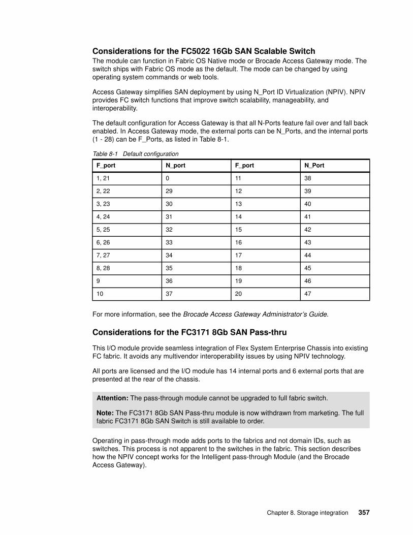
Considerations for the FC5022 16Gb SAN Scalable SwitchThe module can function in Fabric OS Native mode or Brocade Access Gateway mode. The switch ships with Fabric OS mode as the default. The mode can be changed by using operating system commands or web tools.
Access Gateway simplifies SAN deployment by using N_Port ID Virtualization (NPIV). NPIV provides FC switch functions that improve switch scalability, manageability, and interoperability.
The default configuration for Access Gateway is that all N-Ports feature fail over and fall back enabled. In Access Gateway mode, the external ports can be N_Ports, and the internal ports (1 - 28) can be F_Ports, as listed in Table 8-1.
Table 8-1 Default configuration
For more information, see the Brocade Access Gateway Administrator’s Guide.
Considerations for the FC3171 8Gb SAN Pass-thru
This I/O module provide seamless integration of Flex System Enterprise Chassis into existing FC fabric. It avoids any multivendor interoperability issues by using NPIV technology.
All ports are licensed and the I/O module has 14 internal ports and 6 external ports that are presented at the rear of the chassis.
Operating in pass-through mode adds ports to the fabrics and not domain IDs, such as switches. This process is not apparent to the switches in the fabric. This section describes how the NPIV concept works for the Intelligent pass-through Module (and the Brocade Access Gateway).
F_port N_port F_port N_Port
1, 21 0 11 38
2, 22 29 12 39
3, 23 30 13 40
4, 24 31 14 41
5, 25 32 15 42
6, 26 33 16 43
7, 27 34 17 44
8, 28 35 18 45
9 36 19 46
10 37 20 47
Attention: The pass-through module cannot be upgraded to full fabric switch.
Note: The FC3171 8Gb SAN Pass-thru module is now withdrawn from marketing. The full fabric FC3171 8Gb SAN Switch is still available to order.
Chapter 8. Storage integration 357
The following basic types of ports are used in FC fabrics:
� N_Ports (node ports) represent an end-point FC device (such as host, storage system, or tape drive) that is connected to the FC fabric.
� F_Ports (fabric ports) are used to connect N_Ports to the FC switch (that is, the host HBA’s N_port is connected to the F_Port on the switch).
� E_Ports (expansion ports) provide interswitch connections. If you must connect one switch to another, E_ports are used. The E_port on one switch is connected to the E_Port on another switch.
When one switch is connected to another switch in the FC fabric, it uses the Domain ID to uniquely identify itself in the SAN (as with a switch address). Because every switch in the fabric has the Domain ID and this ID is unique in the SAN, the number of switches and number of ports is limited. This limitation, in turn, limits SAN scalability. For example, QLogic theoretically supports up to 239 switches, and McDATA supports up to 31 switches.
Another concern with E_Ports is an interoperability issue between switches from different vendors. In many cases, only the so-called “interoperability mode” can be used in these fabrics, which disables most of the vendor’s advanced features.
Each switch requires some management tasks to be performed on it. Therefore, an increased number of switches increases the complexity of the management solution, especially in heterogeneous SANs that consist of multivendor fabrics. NPIV technology helps to address these issues.
Initially, NPIV technology was used in virtualization environments to share one HBA with multiple virtual machines and assign unique port IDs to each of them. You can use this configuration to separate traffic between virtual machines (VMs). You can manage VMs in the same way as physical hosts; that is, by zoning fabric or partitioning storage.
For example, if NPIV is not used, every virtual machine shares one HBA with one worldwide name (WWN). This restriction means that you cannot separate traffic between these systems and isolate logical unit numbers (LUNs) because they use the same ID.
However, when NPIV is used, every VM has its own port ID and these port IDs are treated as N_Ports by the FC fabric. You can perform storage partitioning or zoning that is based on the port ID of the VM. The switch that the virtualized HBAs are connected to must support NPIV as well. For more information, see the documentation that is included with the FC switch.
The Flex System FC3171 8Gb SAN Pass-thru, and the FC5022 switch in Brocade Access Gateway mode use the NPIV technique. The technique presents the node’s port IDs as N_Ports to the external fabric switches. This process eliminates the need for E_Ports connections between the Enterprise Chassis and external switches. In this way, all 14 internal nodes FC ports are multiplexed and distributed across external FC links and presented to the external fabric as N_Ports.
This configuration means that external switches that are connected to the chassis that are configured for Fibre pass-through do not see the pass-through module. Instead, they see only N_ports that are connected to the F_ports. This configuration can help to achieve a higher port count for better scalability without the use of Domain IDs, and avoid multivendor interoperability issues. However, modules that operate in Pass-Thru cannot be directly attached to the storage system. They must be attached to an external NPIV-capable FC switch. For more information, see the switch documentation about NPIV support.
358 Lenovo Flex System Products and Technology
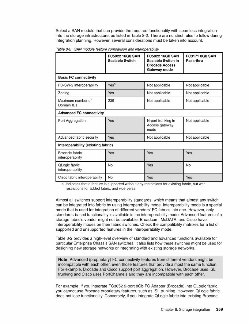
Select a SAN module that can provide the required functionality with seamless integration into the storage infrastructure, as listed in Table 8-2. There are no strict rules to follow during integration planning. However, several considerations must be taken into account.
Table 8-2 SAN module feature comparison and interoperability
Almost all switches support interoperability standards, which means that almost any switch can be integrated into fabric by using interoperability mode. Interoperability mode is a special mode that is used for integration of different vendors’ FC fabrics into one. However, only standards-based functionality is available in the interoperability mode. Advanced features of a storage fabric’s vendor might not be available. Broadcom, McDATA, and Cisco have interoperability modes on their fabric switches. Check the compatibility matrixes for a list of supported and unsupported features in the interoperability mode.
Table 8-2 provides a high-level overview of standard and advanced functions available for particular Enterprise Chassis SAN switches. It also lists how these switches might be used for designing new storage networks or integrating with existing storage networks.
For example, if you integrate FC3052 2-port 8Gb FC Adapter (Brocade) into QLogic fabric, you cannot use Brocade proprietary features, such as ISL trunking. However, QLogic fabric does not lose functionality. Conversely, if you integrate QLogic fabric into existing Brocade
FC5022 16Gb SAN Scalable Switch
FC5022 16Gb SAN Scalable Switch in Brocade Access Gateway mode
FC3171 8Gb SAN Pass-thru
Basic FC connectivity
FC-SW-2 interoperability Yesa
a. Indicates that a feature is supported without any restrictions for existing fabric, but with restrictions for added fabric, and vice versa.
Not applicable Not applicable
Zoning Yes Not applicable Not applicable
Maximum number of Domain IDs
239 Not applicable Not applicable
Advanced FC connectivity
Port Aggregation Yes N-port trunking in Access gateway mode
Not applicable
Advanced fabric security Yes Not applicable Not applicable
Interoperability (existing fabric)
Brocade fabric interoperability
Yes Yes Yes
QLogic fabric interoperability
No Yes No
Cisco fabric interoperability No Yes Yes
Note: Advanced (proprietary) FC connectivity features from different vendors might be incompatible with each other, even those features that provide almost the same function. For example, Brocade and Cisco support port aggregation. However, Brocade uses ISL trunking and Cisco uses PortChannels and they are incompatible with each other.
Chapter 8. Storage integration 359
fabric, placing all Brocade switches in interoperability mode loses Advanced Fabric Services functions.
If you plan to integrate Enterprise Chassis into an FC fabric that is not listed Table 8-2 on page 359, QLogic might be a good choice. However, this configuration is possible with interoperability mode only, so extended functions are not supported. A better method is to use the FC3171 8Gb SAN Pass-thru or Brocade Access Gateway.
Selection of the FC5022 16Gb SAN Scalable Switch is suggested when the Enterprise Chassis is integrated into existing Brocade fabric or when advanced FC connectivity is required. You might use this switch when several Enterprise Chassis are connected to high-performance storage systems.
If you plan to use advanced features, such as ISL trunking, you might need to acquire specific licenses for these features.
If the Enterprise Chassis is attached to a storage system, then the support statement is provided by the storage system’s vendor. It is wise to check that the configuration is supported prior to implementation. Most storage vendors will publish support matrix information, where the Server, OS type, HBA version and driver level, switch model, Top of Rack Switch Model and connection protocol is defined. For more information about supported configurations, see the vendor compatibility information.
For information about compatibility, see the following resources:
� For Flex System, the Flex System Interoperability Guide:
http://lenovopress.com/fsig
� For IBM Storwize V3700, V5000 and V7000, the IBM System Storage Interoperation Center (SSIC):
http://ibm.com/systems/support/storage/ssic/interoperability.wss
8.4 FCoE
One common way to reduce administration costs is by converging technologies that are implemented on separate infrastructures. FCoE removes the need for separate Ethernet and FC HBAs on the servers. Instead, a Converged Network Adapter (CNA) is installed in the server.
Although Lenovo does not mandate the use of FCoE, the choice of using separate Ethernet and SAN switches inside the chassis or choosing a converged FCoE solution is left up to the client. Flex System offers both connectivity solutions.
A CNA presents what appears to be an NIC and an HBA to the operating system, but the “physical” output from of the node is 10 Gb Ethernet. The adapter can either be an integrated 10 Gb LOM with FCoE upgrade applied, or it can be a converged adapter such as the CN4052S 2-port 10Gb Virtual Fabric Adapter with the optional Feature on Demand option applied that enables FCoE.
The CNA is then connected via the chassis midplane to an internal switch that passes these FCoE packets onwards to an external switch that contains a Fibre Channel Forwarder (where
Tip: The use of FC storage fabric from the same vendor often avoids possible operational, management, and troubleshooting issues.
360 Lenovo Flex System Products and Technology
the FC is “broken out”, such as the EN4093R), or by using a switch that is integrated inside the chassis that includes an FC Forwarder. Such a switch is the CN4093 10Gb Converged Scalable Switch, which can break out FC and Ethernet to the rear of the Flex System chassis. The CN4093 10Gb Converged Scalable Switch has external Omni ports that can be configured as FC or Ethernet.
For information about compatibility, see the following resources:
� Flex System Interoperability Guide (FSIG):
http://lenovopress.com/fsig
� IBM System Storage Interoperation Center:
http://ibm.com/systems/support/storage/ssic/interoperability.wss
8.5 iSCSI
iSCSI uses a traditional Ethernet network for block I/O between storage system and servers. Servers and storage systems are connected to the LAN and use iSCSI to communicate with each other. Because iSCSI uses a standard TCP/IP stack, you can use iSCSI connections across LAN or wide area network (WAN) connections.
A software iSCSI initiator is specialized software that uses a server’s processor for iSCSI protocol processing. A hardware iSCSI initiator exists as microcode that is built into the LAN on Motherboard (LOM) on the node or on the I/O Adapter if it is supported.
Both software and hardware initiator implementations provide iSCSI capabilities for Ethernet NICs. However, an operating system driver can be used only after the locally installed operating system is turned on and running. In contrast, the NIC built-in microcode is used for boot-from-SAN implementations, but cannot be used for storage access when the operating system is already running.
For information about compatibility, see the storage vendors interoperability sites and resources for your chosen storage.
Software initiators can be obtained from the operating system vendor. For example, Microsoft offers a software iSCSI initiator for download for Windows Server 2012 at no charge. It is included as standard, as a startable service with Windows Server 2016. The initiators also can be obtained as a part of an NIC firmware upgrade (if supported by NIC).
If you plan for redundancy, you must use multipath drivers. The drivers are provided by the operating system vendor for iSCSI implementations, even if you plan to use hardware initiators.
It is possible to implement HA clustering solutions by using iSCSI, but certain restrictions might apply. For more information, see the storage system vendor compatibility guides.
When you plan your iSCSI solution, consider the following requirements:
� Flex System Enterprise Chassis nodes, initiators, and operating system are supported by an iSCSI storage system. For more information, see the compatibility guides from the storage vendor.
Tip: Consider the use of a separate network segment for iSCSI traffic. That is, isolate NICs, switches or virtual local area networks (VLANs), and storage system ports that participate in iSCSI communications from other traffic.
Chapter 8. Storage integration 361
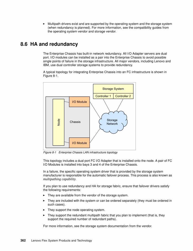
� Multipath drivers exist and are supported by the operating system and the storage system (when redundancy is planned). For more information, see the compatibility guides from the operating system vendor and storage vendor.
8.6 HA and redundancy
The Enterprise Chassis has built-in network redundancy. All I/O Adapter servers are dual port. I/O modules can be installed as a pair into the Enterprise Chassis to avoid possible single points of failure in the storage infrastructure. All major vendors, including Lenovo and IBM, use dual controller storage systems to provide redundancy.
A typical topology for integrating Enterprise Chassis into an FC infrastructure is shown in Figure 8-1.
Figure 8-1 Enterprise Chassis LAN infrastructure topology
This topology includes a dual port FC I/O Adapter that is installed onto the node. A pair of FC I/O Modules is installed into bays 3 and 4 of the Enterprise Chassis.
In a failure, the specific operating system driver that is provided by the storage system manufacturer is responsible for the automatic failover process. This process is also known as multipathing capability.
If you plan to use redundancy and HA for storage fabric, ensure that failover drivers satisfy the following requirements:
� They are available from the vendor of the storage system.
� They are included with the system or can be ordered separately (they must be ordered in such cases).
� They support the node operating system.
� They support the redundant multipath fabric that you plan to implement (that is, they support the required number of redundant paths).
For more information, see the storage system documentation from the vendor.
Controller 2
Chassis
I/O Module
StorageNetwork
Controller 1
Storage System
Nod
e
I/O Module
362 Lenovo Flex System Products and Technology
8.7 Performance
Performance is an important consideration during storage infrastructure planning. Providing the required end-to-end performance for your SAN can be accomplished in several ways.
The storage system’s failover driver can provide load balancing across redundant paths in addition to HA. If you plan to use such drivers, ensure that they satisfy the following requirements:
� They are available from the storage system vendor.
� They are included with the system, or can be ordered separately.
� They support the node operating system.
� They support the multipath fabric that you plan to implement. That is, they support the required number of paths implemented.
Also, you can use static LUN distribution between two storage controllers in the storage system. Some LUNs are served by controller 1 and others are served by controller 2. A zoning technique can also be used with static LUN distribution if you have redundant connections between FC switches and the storage system controllers.
Trunking or PortChannels between FC or Ethernet switches can be used to increase network bandwidth, which increases performance. Trunks in the FC network use the same concept as in standard Ethernet networks. Several physical links between switches are grouped into one logical link with increased bandwidth. This configuration is typically used when an Enterprise Chassis is integrated into advanced FC infrastructures. However, the FC5022 16Gb SAN Scalable Switch supports trunking only. Also, this feature is optional and requires the purchase of another license.
For more information, see the storage system vendor documentation and the switch vendor documentation.
8.8 Backup solutions
Backup is an important consideration when you deploy infrastructure systems. First, you must decide which type of backup solution to implement - either software defined storage or tape backup solution. Data can be backed up by using the following methods:
� Centralized LAN backup with dedicated backup server (compute node in the chassis) with FC-attached tape autoloader or tape library
� Centralized LAN backup with dedicated backup server (server external to the chassis) with FC-attached tape autoloader or tape library
� LAN-free backup with FC-attached tape autoloader or library (for more information, see 8.8.2, “LAN-free backup for nodes” on page 365)
If you plan to use a node as a dedicated backup server or LAN-free backup for nodes, use only certified tape autoloaders and tape libraries. If you plan to use a dedicated backup server on a non-Enterprise Chassis system, use tape devices that are certified for that server. Also, verify that the tape device and type of backup you select are supported by the backup software you plan to use.
Gaining popularity are Software Defined Storage solutions, that provide alternatives to conventional disk and tape backups, one such offering is Cloudian and Lenovo have a
Chapter 8. Storage integration 363
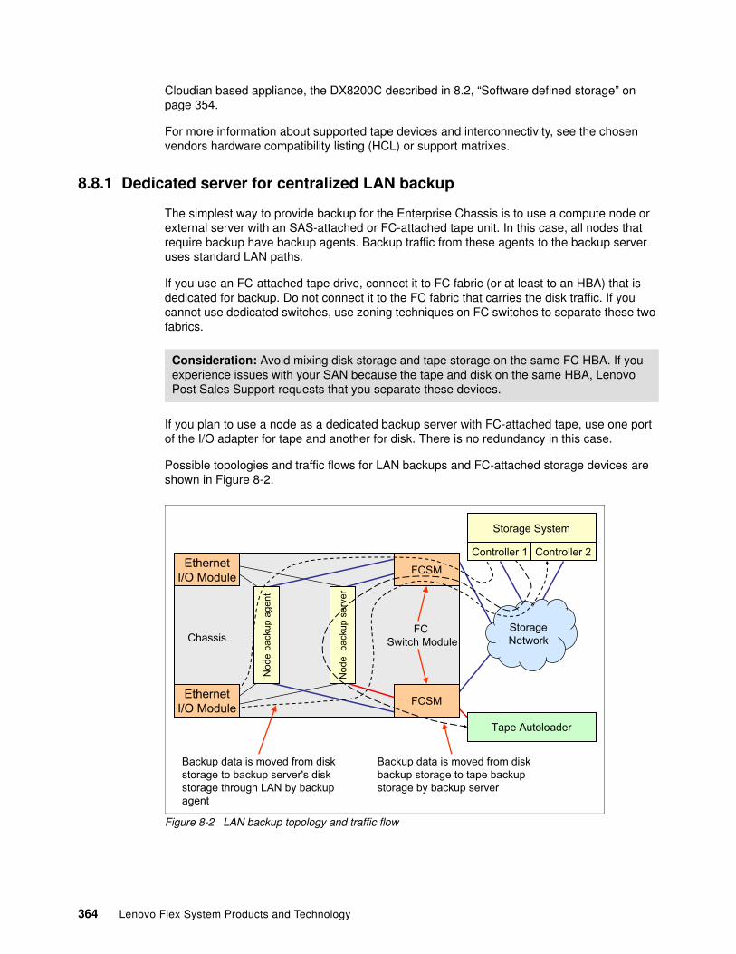
Cloudian based appliance, the DX8200C described in 8.2, “Software defined storage” on page 354.
For more information about supported tape devices and interconnectivity, see the chosen vendors hardware compatibility listing (HCL) or support matrixes.
8.8.1 Dedicated server for centralized LAN backup
The simplest way to provide backup for the Enterprise Chassis is to use a compute node or external server with an SAS-attached or FC-attached tape unit. In this case, all nodes that require backup have backup agents. Backup traffic from these agents to the backup server uses standard LAN paths.
If you use an FC-attached tape drive, connect it to FC fabric (or at least to an HBA) that is dedicated for backup. Do not connect it to the FC fabric that carries the disk traffic. If you cannot use dedicated switches, use zoning techniques on FC switches to separate these two fabrics.
If you plan to use a node as a dedicated backup server with FC-attached tape, use one port of the I/O adapter for tape and another for disk. There is no redundancy in this case.
Possible topologies and traffic flows for LAN backups and FC-attached storage devices are shown in Figure 8-2.
Figure 8-2 LAN backup topology and traffic flow
Consideration: Avoid mixing disk storage and tape storage on the same FC HBA. If you experience issues with your SAN because the tape and disk on the same HBA, Lenovo Post Sales Support requests that you separate these devices.
Chassis
Nod
e ba
ckup
age
nt
EthernetI/O Module
Nod
e b
acku
p se
rver
Tape Autoloader
FCSM
StorageNetwork
FCSM
EthernetI/O Module
Controller 1 Controller 2
Storage System
FCSwitch Module
Backup data is moved from diskbackup storage to tape backupstorage by backup server
Backup data is moved from diskstorage to backup server's diskstorage through LAN by backupagent
364 Lenovo Flex System Products and Technology
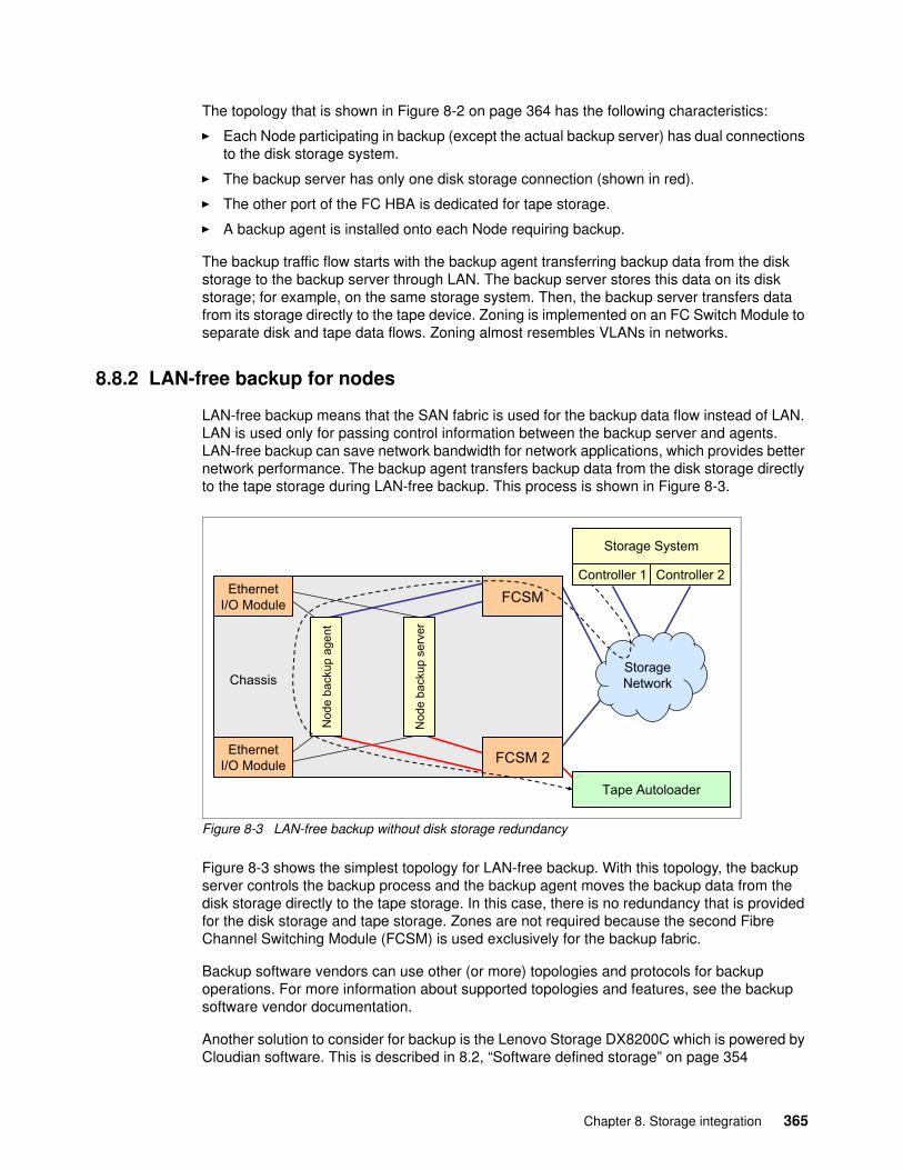
The topology that is shown in Figure 8-2 on page 364 has the following characteristics:
� Each Node participating in backup (except the actual backup server) has dual connections to the disk storage system.
� The backup server has only one disk storage connection (shown in red).
� The other port of the FC HBA is dedicated for tape storage.
� A backup agent is installed onto each Node requiring backup.
The backup traffic flow starts with the backup agent transferring backup data from the disk storage to the backup server through LAN. The backup server stores this data on its disk storage; for example, on the same storage system. Then, the backup server transfers data from its storage directly to the tape device. Zoning is implemented on an FC Switch Module to separate disk and tape data flows. Zoning almost resembles VLANs in networks.
8.8.2 LAN-free backup for nodes
LAN-free backup means that the SAN fabric is used for the backup data flow instead of LAN. LAN is used only for passing control information between the backup server and agents. LAN-free backup can save network bandwidth for network applications, which provides better network performance. The backup agent transfers backup data from the disk storage directly to the tape storage during LAN-free backup. This process is shown in Figure 8-3.
Figure 8-3 LAN-free backup without disk storage redundancy
Figure 8-3 shows the simplest topology for LAN-free backup. With this topology, the backup server controls the backup process and the backup agent moves the backup data from the disk storage directly to the tape storage. In this case, there is no redundancy that is provided for the disk storage and tape storage. Zones are not required because the second Fibre Channel Switching Module (FCSM) is used exclusively for the backup fabric.
Backup software vendors can use other (or more) topologies and protocols for backup operations. For more information about supported topologies and features, see the backup software vendor documentation.
Another solution to consider for backup is the Lenovo Storage DX8200C which is powered by Cloudian software. This is described in 8.2, “Software defined storage” on page 354
Chassis
Nod
e ba
ckup
age
nt
EthernetI/O Module
Nod
e ba
ckup
ser
ver
Tape Autoloader
FCSM 2
StorageNetwork
FCSM
EthernetI/O Module
Controller 1 Controller 2
Storage System
Chapter 8. Storage integration 365
8.9 Boot from SAN
Boot from SAN (or SAN Boot) is a technique that is used when the node in the chassis has no local disk drives. It uses an external storage system LUN to boot the operating system. The operating system and data are on the SAN. This technique is commonly used to provide higher availability and better usage of the systems storage (where the operating system is). Hot spare Nodes or “Rip-n-Replace” techniques can also be easily implemented by using Boot from SAN.
8.9.1 Implementing Boot from SAN
Boot from SAN has become less popular in recent times, mainly due the availability of low cost storage media such as SD Cards and USB memory sticks.
None the less, to successfully implement SAN Boot, the following conditions must be met.
� Storage system supports SAN Boot� Operating system supports SAN Boot� FC HBAs, or iSCSI initiators support SAN Boot
For more information, see the respective storage system compatibility guides.
8.9.2 iSCSI SAN Boot specific considerations
iSCSI SAN Boot enables a diskless node to be started from an external iSCSI storage system. You can use the onboard 10 Gb Virtual Fabric LOM on the node or an I/O adapter.
The following adapters support iSCSI:
� Flex System CN4052S 10Gb Virtual Fabric Adapter
� Flex System CN4054S 10Gb Virtual Fabric Adapter
� Flex System CN4058S 10Gb Virtual Fabric Adapter
� Flex System CN4022 10 Gb Converged Adapter
For the latest compatibility information, see the relevant storage vendors compatibility guides.
For more information about IBM System Storage compatibility, see the IBM System Storage Interoperability Center at this website:
http://www.ibm.com/systems/support/storage/config/ssic
366 Lenovo Flex System Products and Technology
ronyms
3DS RDIMM 3D Stacked Registered Dual Inline Memory Module
AC alternating current
ACL access control list
ACPI Advanced Configuration and Power Interface
ADDDC Adaptive Double-Device Data Correction
AER Advanced Error Reporting
AES-NI Advanced Encryption Standard New Instructions
AFA All Flash Array
AFT adapter fault tolerance
AHCI Advance Host Controller Interface
AHV Acropolis Hypervisor
ALB adaptive load balancing
AMM advanced management module
AMP Apache, MySQL, and PHP/Perl
ANS Advanced Network Services
ANSI American National Standards Institute
AOC active optical cable
API application programming interface
ARP Address Resolution Protocol
AS Australian Standards
ASEAN Association of Southeast Asian Nations
ASHRAE American Society of Heating, Refrigerating and Air-Conditioning Engineers
ASIC application-specific integrated circuit
ASU Advanced Settings Utility™
AVX Advanced Vector Extensions
BACS Broadcom Advanced Control Suite
BASP Broadcom Advanced Server Program
BE Broadband Engine
BGP Border Gateway Protocol
BIOS basic input/output system
BMC baseboard management controller
BP backplane
BPDU Bridge Protocol Data Unit
Abbreviations and ac
© Copyright Lenovo 2018. All rights reserved.
BRD board
CA certificate authority
CEE Converged Enhanced Ethernet
CEM Card Electromechanical
CFM cubic feet per minute
CHAP Challenge Handshake Authentication Protocol
CIM Common Information Model
CLI command-line interface
CMM Chassis Management Module
CNA Converged Network Adapter
CO Central Office
COD configuration on disk
CORE Custom Opportunity Request for Evaluation
CPM Copper Pass-thru Module
CPU central processing unit
CRAC computer room air conditioning
CRTM Core Root of Trusted Measurements
CRU customer replacable unit
CTO configure to order
DAC direct-attach copper
DC direct current
DCB Data Center Bridging
DCBX Data Center Bridging Exchange
DCG data center group
DCNM Data Center Network Manager
DDF Disk Data Format
DDR double data rate
DHCP Dynamic Host Configuration Protocol
DIMM dual inline memory module
DMA direct memory access
DMI Desktop Management Interface
DMTF Distributed Management Task Force
DPC DIMMs per channel
DPI Distributed Power Interconnect
DPOD Dynamic Ports on Demand
DRAM dynamic random-access memory
367
DRTM Dynamic Root of Trust Measurement
DSA Dynamic System Analysis™
DWPD drive writes per day
EBM Extended Battery Module
ECC error checking and correcting
ECP Edge Control Protocol
EE Equipment Engineering
EIA Electronic Industries Alliance
ELD edge loop detection
ELW extended long wave
EMC Electromagnetic Compatibility
EMEA Europe, the Middle East and Africa
ESB Enterprise Switch Bundle
ESD Electrostatic discharge
ETE everything-to-everything
ETS Enhanced Transmission Selection
ETSI European Telecommunications Standards Institute
EVB Edge Virtual Bridging
EVRD Enterprise Voltage Regulator Down
FC Fibre Channel
FC-AL Fibre Channel Arbitrated Loop
FCF Fibre Channel Forwarder
FCoE Fibre Channel over Ethernet
FCP Fibre Channel protocol
FCSM Fibre Channel Switching Module
FDR fourteen data rate
FDX full duplex
FET Fabric Extender Transceivers
FEX Fabric Extender
FFDC first failure data capture
FIFO first in, first out
FIP FCoE Initialization Protocol
FIPS Federal Information Processing Standards
FLR Function Level Reset
FMA fused multiply-add
FOD features on demand
FPMA Fabric Provided MAC Addressing
FSB FIP Snooping Bridges
FSIF Flex System Interconnect Fabric
FSIG Flex System Interoperability Guide
FSP flexible service processor
FTP File Transfer Protocol
FTSS Field Technical Sales Support
GAV generally available variant
GB gigabyte
GPU graphics processing unit
GSO Generic Segmentation Offload
GT gigatransfers
GUI graphical user interface
HA high availability
HBA host bus adapter
HCA host channel adapter
HCL hardware compatibility list
HDD hard disk drive
HPC high-performance computing
HS hot swap
HSRP Hot Standby Router Protocol
HT Hyper-Threading
HTK Hong Kong, Taiwan and Korea
HVDC high voltage direct current
HW hardware
I/O input/output
IB InfiniBand
IBM International Business Machines
IBTA InfiniBand Trade Association
ID identifier
IEC International Electrotechnical Commission
IEEE Institute of Electrical and Electronics Engineers
IGMP Internet Group Management Protocol
IMG image
IMM integrated management module
INCITS International Committee for Information Technology Standards
IOPS input/output operations per second
IP Internet Protocol
IPC interprocess communication
IPMI Intelligent Platform Management Interface
IS information store, industry standard
ISL inter-switch links
ISO International Organization for Standardization
ISP Internet service provider
ISSU In-Service Software Upgrade
IT information technology
368 Lenovo Flex System Products and Technology
ITE IT Element
JBOD just a bunch of disks
KB kilobyte
KVM keyboard video mouse
LACP Link Aggregation Control Protocol
LACPDU LACP Data Unit
LAG link aggregation group
LAN local area network
LDAP Lightweight Directory Access Protocol
LED light emitting diode
LFF large form factor
LGA land grid array
LKMS Lenovo Key Management System
LLDP Link Layer Discovery Protocol
LOM LAN on Motherboard
LP low profile
LPC Local Procedure Call
LPVID Logical Port VLAN ID
LR long range
LRDIMM load-reduced DIMM
LSO Large send offload
LUN logical unit number
LW long wave
MAC media access control
MB megabyte
MIB management information base
MLC Multi-Level Cell
MMF multi-mode fiber
MPO Multi-fiber Push On
MSI Message Signaled Interrupts
MSTP Multiple Spanning Tree Protocol
MT machine type
MTBF mean time between failures
NAS network-attached storage
NC North Carolina
NDIS Network Driver Interface Specification
NEBS Network Equipment-Building System
NEMA National Electrical Manufacturers Association
NFS Network File System
NIC network interface card
NIST National Institute of Standards and Technology
NL nearline
NLS National Language Support
NMI non-maskable interrupt
NPIV N-Port ID Virtualization
NPV N-Port Virtualization
NS not supported
NTP Network Time Protocol
NUMA Non-Uniform Memory Architecture
NVMe Non Volatile Memory Express
NVGRE Network Virtualization using Generic Routing Encapsulation
OEM Original equipment manufacturer
OFED OpenFabrics Enterprise Distribution
OOB out of band
OPM Optical Pass-Thru Module
OS operating system
OSPF Open Shortest Path First
OVF Open Virtualization Format
PCH Platform Controller Hub
PCI Peripheral Component Interconnect
PCIe PCI Express
PDU power distribution unit
PEN PCIe Expansion Node
PEP policy enforcement point
PF power factor
PFC Priority-Based Flow Control
PIM Protocol Independent Multicast
pNIC physical network interface card
PSU power supply unit
PTP Precision Time Protocol
PVID Port VLAN ID
PVRST Per VLAN Rapid Spanning Tree
PVST Per-VLAN Spanning Tree
PXE Preboot Execution Environment
QDR quad data rate
QPI QuickPath Interconnect
QSFP Quad Small Form-factor Pluggable
RAID redundant array of independent disks
RAM random access memory
RAS remote access services; row address strobe
Abbreviations and acronyms 369
RDHX Rear Door Heat Exchanger
RDIMM registered DIMM
RDMA remote direct memory access
REST Representational State Transfer
RFC request for comments
RHEL Red Hat Enterprise Linux
RIP Routing Information Protocol
RISC Reduced instruction set computer
RMON Remote Monitoring
ROC RAID-on-Chip
ROM read-only memory
RPM revolutions per minute
RPVST Rapid Per-VLAN Spanning Tree
RSCN Registered State Change Notification
RSS Receive-Side Scaling
RSTP Rapid Spanning Tree Protocol
RTN Return
S&S Subscription & Support
SAN storage area network
SAO Server Application Optimization
SAS Serial Attached SCSI
SATA Serial ATA
SCO Serial Conversion Option
SCP SCP
SCSI Small Computer System Interface
SD Secure Digital
SDDC single device data correction
SDMC Systems Director Management Console
SDR single data rate
SDS software defined storage
SED self-encrypting drive
SEN Storage Expansion Node
SERDES Serializer/DeSerializer
SFF small form factor
SFP Small Form-factor Pluggable
SFT switch fault tolerance
SIM System Interconnect Module
SLB Smart Load Balancing
SLC Single-Level Cell
SLES SUSE Linux Enterprise Server
SLP Service Location Protocol
SLP Service Location Protocol
SMB Server Message Block
SMI-S Storage Management Initiative Specification
SNIA Storage Networking Industry Association
SNMP Simple Network Management Protocol
SNSC System Networking Switch Center
SPAR switch partitioning
SQL structured query language
SR short range
SR-IOV System Root I/O Virtualization
SRAM static random-access memory
SSD solid-state drive
SSH Secure Shell
SSIC IBM System Storage Interoperation Center
SSL Secure Sockets Layer
STP Spanning Tree Protocol
SW short wave
SerDes Serializer-Deserializer
TCG Trusted Computing Group
TCM Trusted Cryptographic Module
TCO total cost of ownership
TCP Transmission Control Protocol
TDI Tailored Data center Integration
TDP thermal design power
TFTP Trivial File Transfer Protocol
TLC triple-level cell
TLV Type-Length Value
TNC Trusted Network Connect
TOE TCP Offload Engine
TOR top of rack
TPM Trusted Platform Module
TRILL Transparent interconnection of lots of links
TRL Target Rate Limiting
TSO TCP Segmentation offload
TSS Transmit Side Scaling
TXT Trusted Execution Technology
UCO USB Conversion Option
UDIMM unbuffered DIMM
UDLD Unidirectional link detection
UDP User Data Protocol
UEFI Unified Extensible Firmware Interface
370 Lenovo Flex System Products and Technology
UFP Unified Fabric Port
UI user interface
UL Underwriters Laboratories
UPI Ultra Path Interconnect
UPS uninterruptible power supply
URL Uniform Resource Locator
USB universal serial bus
UTP unshielded twisted pair
VA volts-amps
VAC volts alternating current
VCS Virtual Cluster Switching
VE Virtualization Engine
VEB Virtual Ethernet Bridging
VEPA Virtual Ethernet Port Aggregator
VF virtual functions
VFA Virtual Fabric Adapter
VGA video graphics array
VIOS Virtual I/O Server
vLAG Virtual Link Aggregation Groups
VLAN virtual LAN
VM virtual machine
VMQ virtual machine queue
vNIC Virtual Network Interface Card
VPD vital product data
VPI Virtual Protocol Interconnect
VRRP Virtual Router Redundancy Protocol
VSI Virtual Station Interface
VSS Virtual Switch System
VT Virtualization Technology
VXLAN VMware Virtual Extensible LAN
WAN wide area network
WOL Wake-on-LAN
WRR Weighted Round Robin
WW worldwide
WWN Worldwide Name
XCC XClarity Controller
Abbreviations and acronyms 371

372 Lenovo Flex System Products and Technology
Related publications
The publications that are listed in this section are considered particularly suitable for a more detailed discussion of the topics that are covered in this book.
Lenovo Press publications
The following publications provide more information about the topics in this publication:
� Reference documents:
– Flex System Interoperability Guide:
http://lenovopress.com/fsig
– Lenovo Storage Interoperability Links
https://lenovopress.com/lp0584
– xREF: System x Reference:
http://lenovopress.com/xref
– Operating System Interoperability Guide:
http://lenovopress.com/osig
� Books and papers:
– Flex System Networking in an Enterprise Data Center, 2nd Edition, REDP-4834:
http://lenovopress.com/redp4834
– Migrating from BladeCenter to Flex System, REDP-4887:
http://lenovopress.com/redp4887
– Using System x Features on Demand, REDP-4895:
http://lenovopress.com/redp4895
– NIC Virtualization in Flex System Fabric Solutions, SG24-8223:
http://lenovopress.com/sg248223
– Lenovo Flex System X6 Compute Node Planning and Implementation Guide, SG24-8227:
http://lenovopress.com/sg248227
– Flex System Interconnect Fabric Technical Overview and Planning Considerations, REDP-5106:
http://lenovopress.com/redp5106
– Implementing Systems Management of Flex System, SG24-8060:
http://lenovopress.com/sg248060
– Lenovo Flex System Higher Voltage DC Solutions, REDP5180:
http://lenovopress.com/redp5180
© Copyright Lenovo 2018. All rights reserved. 373
You can search for, view, download, or order these documents and other books and papers at this website:
http://lenovopress.com
Online resources
The following websites and web pages are also relevant as further information sources:
� Flex System Interoperability Guide:
http://lenovopress.com/fsig
� Configuration and Option Guide:
http://www.lenovo.com/us/en/cog/
� Flex System Enterprise Chassis Power Requirements Guide:
https://support.lenovo.com/us/en/documents/lnvo-powinf
� Flex System Information Center:
http://publib.boulder.ibm.com/infocenter/flexsys/information/index.jsp
� IBM System Storage Interoperation Center:
http://www.ibm.com/systems/support/storage/ssic
� Integrated Management Module II User’s Guide:
https://support.lenovo.com/docs/MIGR-5086346
� ServerProven for Flex System:
http://www.lenovo.com/us/en/serverproven/flexsystem.shtml
� xREF - System x Server Reference:
http://lenovopress.com/xref
� Lenovo Power Configurator:
https://support.lenovo.com/us/en/documents/LNVO-PWRCONF
374 Lenovo Flex System Products and Technology
(1.0” spine)0.875”<
->1.498”
460 <->
788 pages
Lenovo Flex System Products and Technology
Lenovo Flex System Products and Technology
Lenovo Flex System Products and
Lenovo Flex System Products and Technology

Lenovo Flex System Products and
Lenovo Flex System Products and

BUILDING TECHNICAL INFORMATION BASED ON PRACTICAL EXPERIENCE
At Lenovo Press, we
bring together experts
to produce technical
publications around
topics of importance to
you, providing
information and best
practices for using
Lenovo products and
solutions to solve IT
challenges.
Lenovo Flex System Products and Technology
Describes the Flex System and new ThinkSystem offerings
Covers the latest products, including the new SN550 and SN850 Compute Nodes
Provides details about available I/O modules and expansion options
Explains networking and storage configurations
To meet today’s complex and ever-changing business demands, you need a solid foundation of compute, storage, networking, and software resources. This system must be simple to deploy, and be able to quickly and automatically adapt to changing conditions. You also need to use broad expertise and proven guidelines in systems management, applications, hardware maintenance, and more.
Lenovo® Flex System™ combines no-compromise system designs along with built-in expertise and integrates them into complete, optimized solutions. Central to the Flex System offering is the Enterprise Chassis. This fully integrated infrastructure platform supports a mix of compute, storage, and networking resources to meet the demands of your applications.
The solution is easily scalable with the addition of another chassis with the required nodes, and with Lenovo XClarity™ Administrator, multiple compute nodes, I/O modules, and chassis can be monitored all from a single panel. Flex System is simple to deploy now, and to scale to meet your needs in the future.
This book describes the Flex System offerings that are available from Lenovo. It highlights the technology and features of the chassis, compute nodes, management features, and connectivity options. Guidance also is provided about every major component and networking and storage connectivity.
This book is intended for customers, Lenovo Business Partners, and Lenovo employees who want to know more about the new family of products. It assumes that you have a basic understanding of blade server concepts and general IT knowledge.
Back cover
lenovopress.com/sg248255