Embed Size (px)
Citation preview
LEO-15 Instrument Interface SpecificationRevision 1.2.1 March 3, 2000
Document No. 101352
Oceanographic Systems LaboratoryDepartment of Applied Ocean Physics and Engineering
Woods Hole Oceanographic InstitutionWoods Hole, MA
1.0 Background
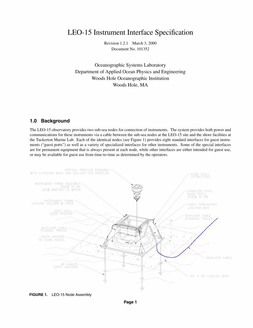
The LEO-15 observatory provides two sub-sea nodes for connection of instruments. The system provides both power andcommunications for these instruments via a cable between the sub-sea nodes at the LEO-15 site and the shore facilities atthe Tuckerton Marine Lab. Each of the identical nodes (see Figure 1) provides eight standard interfaces for guest instru-ments (“guest ports”) as well as a variety of specialized interfaces for other instruments. Some of the special interfacesare for permanent equipment that is always present at each node, while other interfaces are either intended for guest use,or may be available for guest use from time-to-time as determined by the operators.
FIGURE 1. LEO-15 Node Assembly
Page 1

LEO-15 Instrument Interface Specification March 3, 2000
1.1 Instrument Interface Model
Subsea instruments are connected to the nodes via diver mateable connectors seen in Figure 2; this figure shows theinstrument frame of a node before installation into the node shell (see also Figure 1). Instrument power is provided fromeach node, and is controlled (turned on or off) by the LEO control computer at the shore station. This computer also mon-itors the nodes and connected instruments for various faults which might occur. Requests for an instrument’s fault/enablestatus or for a change in its on/off state are made to the LEO control computer by any of three methods: interactive (man-ual) request through a telnet session or graphical interface, a request packet sent on the local network, or a request sent toan assigned serial port on the control computer. Power and signal connections to each instrument are strictly under thecontrol of the LEO control computer; any instrument is subject to being turned on or off at any time while the controlcomputer is searching for faults, and may be permanently disabled if it is found to be the cause of a fault. For more infor-mation about instrument control through the LEO control computer, see WHOI/OSL document: 101392, “LEO-15 Soft-ware Interface Specification”; see Section 7.0 for information on obtaining this document.
Instrument data is passed (nearly) transparently through the shore cable between each sub-sea instrument and the user’scomputer at the shore station (shown in Figure 3) via a serial data connection. Instrument data is not passed through orhandled by the LEO control computer (except for the data from a few permanent instruments, such as the verticalprofiler). This approach retains the greatest flexibility for data and control protocols for each instrument, and leaves theresponsibility for, and control of, data storage and dissemination with each user.
1.2 Fault Detection
Several fault detection and protection services are provided by the sub-sea nodes: ground fault detection, water leak detec-tion and over-current protection. If any fault is detected, operators and users are notified by displays on the LEO controlcomputer and also by electronic mail. These node services limit the damage that might occur to an instrument followingan unintended event such as water entry. Early detection of water entry provides the notification needed to recover a failedinstrument, and prompt removal of all power and signals can significantly reduce the damage caused by electrolyticcorrosion. The ground fault detector is the primary detection tool for this purpose; it finds any contact between sea-waterand the electrical circuits of the nodes or connected instruments.
Along with the fault detection benefits comes a responsibility to be a good node “citizen”. The principal requirement isthat no instrument may make an intentional direct-current path from any power bus to seawater, or between any of thepower buses. The first requirement permits unintended ground faults to be detected, because one intentional groundwould mask all others. The second requirement is for safety of equipment and personnel; if a high and low voltage bus are
FIGURE 2. LEO-15 Instrument Frame with Instrument Connectors
Page 2

LEO-15 Instrument Interface Specification March 3, 2000
connected, a fault on the higher voltage bus could drive all circuits on the low voltage bus to a voltage much farther fromseawater than they are designed for or than is expected by personnel. Section 2.0 describes the fault services and require-ments in detail.
1.3 Data Transmission
Most data transfer between sub-sea instruments and the user’s shore equipment is handled as serial data. Each channelbetween an instrument and the surface is completely independent of, and parallel to, every other channel. Most channelsfrom the sub-sea nodes to the shore station are full-duplex, providing symmetrical, bi-directional data flow. Each channelprovides or accepts a serial bit stream with a standard signal level, either: RS232, RS422 or TTL. For the most part theseserial data channels are transparent to the user: a binary level transmitted at one end appears at the other end after a shortbut constant delay.
In addition to the serial data channels, there are two other types of channels available at the nodes. Both are one waychannels that run from the sub-sea nodes to the shore station. One of these is the analog channel type. Each node pro-vides two analog channels with variable gain amplifiers and a bandwidth of 50 kHz (200 kHz sample rate). One of thesechannels is normally dedicated to a hydrophone for acoustic monitoring.
The other type of non-binary channel is for video. Each node has one video channel; there are two connectors on eachnode so that two video sources can be switched to share this channel. The two video connectors are normally dedicated topermanent functions, but may be available by arrangement with the administrators.
2.0 Fault Detection Services
Three kinds of fault services are provided by the node: electrical ground fault detection, water leak detection (optional),and over-current limiting. Some of the concepts presented here may be unfamiliar to users. An understanding of therequirements imposed by these systems is essential to successful operation of instruments attached the LEO-15 nodes.
FIGURE 3. LEO-15 Shore Station
Page 3

LEO-15 Instrument Interface Specification March 3, 2000
2.1 Ground Faults
A ground fault exists whenever a direct-current path connects an electrical conductor to seawater. Ground fault detectionis a very strong method of detecting water intrusion into electrical circuits because it covers all places where electricalconductors go: housings, cables, connectors, etc.; the only exceptions being where circuits are specifically isolated fromthe LEO interface wires. Ground faults are sensed automatically on each of the separate (isolated) power buses availableon each node (240 V, 120 V, 48 V and 15 V, all data commons are connected to the 15 V common). If a fault is detected,instruments using the faulted bus are sequentially turned off until the fault is cleared, thus identifying the faultedinstrument. A faulted instrument will be permanently powered down and notification sent according to priorarrangement.
NOTE
As a result of the procedure for isolating the source of a groundfault, even instruments that are not faulted may have their powerand communications interrupted at any time. Instruments must bedesigned to recover gracefully from power and communicationsinterruptions.
Ground faults are detected by sequentially biasing the common of each power source (240 V, 120 V, 48 V and 15 V) toeach of two test voltages with respect to seawater and then sensing any resulting current flow. For each power bus, the twotest voltages are zero and the respective bus voltage; current is limited to 1 ma by a series resistor of 1 kΩ/volt. Failurelevels are subject to change, but are generally set to 100 µA. Dwell time at each test voltage varies from a half to a fewseconds, with a test cycle time of ten seconds or more. Thus all circuits connected to the nodes have time varying voltageswith respect to seawater; this may affect the measurements made by some sensitive instruments.
NOTE
The 100 µA limit applies to the total leakage of any bus on an entirenode, not to leakage of each individual instrument. Users should besure that the leakage of any one instrument is 10 µA or less.
The ground detection system imposes several constraints on the connection of instruments to the sub-sea nodes:
1. There can be no direct-current path from seawater to any wire that connects to a node interface connector. This pro-hibits the direct connection of instruments that have their circuit commons connected to a metallic case. More andmore instrument makers are avoiding case connections of interface wires, but all instruments should be checked.Common offenders are direct contact conductivity sensors.
2. No instrument can make a direct current path between any two power sources (240 V, 120 V, 48 V and 15 V); thesemust remain isolated from each other for safety reasons and to simplify fault isolation. Connections between the datacommons and the 15 V common are acceptable, as these are already connected in the nodes.
3. No instrument should have more than 1 µF of capacitance between any power wire or common and seawater. Ideally,capacitance to seawater will be limited to 0.1 µF.
Additional discussion regarding interpretation of ground readings can be found in Section 5.2.2, paragraph 10.
It is important to emphasize that many instruments from vendors of oceanographic instrumentation are shipped with con-nector pins that are grounded to a conductive case. This is becoming less common for new instruments, but many existinginstruments have internal grounds. To connect these instruments to the LEO nodes, they must either have their power andsignal wires isolated (CAUTION: see comments about isolated instruments, below), or they must be modified to removethe internal grounds. Most vendors can give advice about how to un-ground their instruments, or can modify them if theinstruments are returned to the factory. Examples of instruments that have caused problems include: many contact con-ductivity probes or cells (most conductivity instruments are of this type, but some are internally isolated from their con-nectors), older Wetlabs fluorometers, and Seabird SBE4 current sensors.
Page 4

LEO-15 Instrument Interface Specification March 3, 2000
If an instrument requires a seawater contact for some direct measurement, or if it requires a case contact for signal integ-rity (shielding), then the offending portion of the instrument must be isolated (both power and signals, but see additionalcomment on isolation, below) from the connections that lead to the LEO node. Note that most instruments do not need adirect case ground for shielding; a 0.1 µF capacitor is usually sufficient.
Designers are strongly encouraged take advantage of the LEO node ground detector by leaving as much instrument cir-cuitry as possible connected to the node wiring. If the choice is made to isolate an instrument from the node wiring, thenit is best to provide the instrument with its own internal ground detector. Simply isolating an instrument, but not groundchecking the isolated portions does not eliminate ground faults, it only eliminates their detectability. Undetected groundfaults can result in: corrosion of the exposed electrical conductors, obscure performance problems, and safety hazards todivers servicing instruments or the nodes. Instruments that contain isolated circuits without ground detection are subjectto being turned off whenever divers are nearby, unless they are shown to be intrinsically safe (maximum fault current lessthan 10 mA, or maximum voltage less than 24 V peak).
2.2 Leaks
The leak detection system is intended to provide early warning of water entry into a pressure housing or oil filled space,before damage is caused by contact with electrical components. A water leak detector consists of a pair of probes (wires,terminals, connector contacts, etc.) arranged at the bottom or perimeter of a space that is intended to stay dry; water bridg-ing the probes closes a circuit and is thus detected. The use of leak detectors is optional, but the facility is provided forusers who want the additional coverage. All standard guest ports are provided with connections for a leak probe, but someof the other interfaces do not have this feature.
The leak detection system allows a more specific determination of water intrusion (exact location and cause) than theground detection system. While the ground detector will be activated by any water entry that establishes a path from sea-water to some point in the electrical system (as well as finding grounds caused by wiring problems other than leaks), theleak detector can find water that has not yet touched the electrical system. However, the “coverage” of a leak probe isrestricted to only those places where bare conductors on the leak circuit exist, e.g. the designed probe location and anyincidental connector pins and terminals.
Leak probes are scanned periodically by biasing them with a +12 V source (with respect to LEAK_COM) in series with a60 kΩ resistor, thus limiting the test current to 200 µA. The leak report is an analog measure of the percentage of this cur-rent that is flowing, but a typical water drop will produce a full scale reading. In large spaces, where a significant volumeof water could collect before damage occurs, resistors can be used to construct a multi-stage probe that gives an earlywarning and information about the rate of water entry.
Leak probes should have contacts about 1/4 to 1/2 inch apart, and no closer than 1/8 inch to the bottom or sides of thevessel. This assures both that a few drops of water can bridge the contact, and also that they can roll away (not stick to theprobes) to reduce false alarms. The leak probe(s) must obviously be installed in the “down” side of an instrument, or mustbe designed to work in all possible orientations on an instrument that has more than one “down”.
All leak circuits (one for each guest that uses it) must be bridged by a diode at the probe (or at the last of a string ofprobes); the diode cathode connects to LEAK and the anode connects to LEAK_COM. Most any diode will do, as thevoltage and current are low; a 1N4002 or 1N4142 would be suitable choices. The diode allows the node to check the con-tinuity to each (last) leak probe by reversing the polarity of the test voltage. The probe will be tested positive with respectto common to look for water across the probe, and negative with respect to common to look for the diode; this allows thecontinuity to the probe to be verified (a probe that shows open but is in fact not even connected, gives false security).
2.3 Over-Current Limiting
Each power outlet on the two sub-sea nodes is supplied from a remotely controlled switch. These switches provide over-current protection to prevent damage to the switches or to the wiring of the node. Secondarily they will limit damage to aconnected instrument; but as the limit values are set to accommodate a high power instrument, a low power one may not
Page 5

LEO-15 Instrument Interface Specification March 3, 2000
be adequately protected. Particular limit settings are listed in the following sections for each power outlet. Over-currentlimiting is automatic both in its application and in recovery following removal of the condition that caused the fault; how-ever, the existence of an over-current condition is neither sensed nor reported by the LEO control computer.
The switches provide uninterrupted DC power for load currents below their limit settings. Above the limit, the switchperiodically turns off and then on again at about a 3 kHz rate. The switch reduces the length of the on-time (the duty-cycle) according to the peak current encountered: shorter on-time for higher peak currents. This characteristic lowers theaverage current being passed by the switch when supplying higher peak current. Mathematically, the current limit charac-teristic is designed to keep the peak current, , times the square root of duty cycle, , approximately equal to the cur-rent limit setting, , , thus reducing the average current while limiting the RMS current (that heats theswitches and wires) to the limit setting. Note that the switches do not simply turn off with an over-load, like a circuitbreaker, but wait in a reduced duty-cycle condition for the over-load to decrease; this allows instrument inputs with largebulk capacitors (e.g. transmitting devices) to start up reliably, even though the discharged capacitor initially looks like ashort-circuit. There can still be start-up problems with some combinations of input capacitance and instrument load; withcapacitances over 10,000 µF, it is best to test the device with the LEO hardware or to consult with Rutgers/WHOI.
3.0 Serial Data Transmission
Most instruments will use the serial telemetry channels for exchange of data. There are two aspects of the serial datatransmission process that cause the actual channels to differ from the ideal discussed in Section 1.3: sampling and delay.The user needs to be aware of these characteristics to the extent that they limit the performance of each channel. Theseconcepts apply to all of the serial channels regardless of their speed or standard signal levels.
Each channel of serial input data is actually sampled at a fixed rate to determine if it is high or low at each sample time.These samples are conveyed to the other end of the cable where they are transmitted to the user’s equipment at a specifiedstandard signal level, in the original sequence, and for the duration of a sample interval. Sample rates of the channels dif-fer, and are tabulated in the following sections. Multiple input data transitions that occur between samples will not bereproduced at the other end. Furthermore, each transition of the input data will be reproduced with a jitter, or time uncer-tainty, of one sample period. Certainly, data that makes transitions more often than the sample rate cannot be accuratelyreproduced, but even lower limits may apply depending on the method used to serialize and de-serialize the data. For typ-ical serial devices, the baud rate must be (in an ideal sense) less than half the sample rate, and practically it needs to be lessthan about one quarter of the sample rate. Thus for a guest port having a sample rate of 200 kHz, the maximum baud rateshould be 50 kbaud.
The delay of any channel is a constant for most purposes. It consists of the sum of three terms: the light propagation timein the fiber, plus a small fixed number of sample periods (2-4), plus the sample jitter time of between zero and one sampleperiod. The light propagation time is approximately 30 µsec for the 9 km path between the sub-sea nodes and the shorestation. The sample period for the second two terms varies from 100 nsec for the high speed channels to 10 µsec for someof the RS232 channels. Thus the range in delays for the various channels falls between 30 and 100 µsec; this would be ashort delay for most applications and can be ignored. The important feature is that the delay is constant (except for thesample jitter), due to the absence of buffering, and thus can be characterized for a critical application.
4.0 Instrument Interfaces
Instruments connect to wet mateable connectors on the Main Junction Box. The layout of these connectors is shown inFigure 4.
At the Shore Station, there is a rack-mounted telemetry box for each node, which provides connections for user’s surfaceequipment to communicate with subsea instruments. Figure 5 shows the arrangement of these connectors. Those connec-tors that are available for general use are described in the following sections.
I pk DIlim I pk D Ilim=
Page 6

LEO-15 Instrument Interface Specification March 3, 2000
FIGURE 4. LEO-15 Main Junction Box Connector Layout
FIGURE 5. LEO-15 Surface Telemetry Box, Rear Panel
Page 7

LEO-15 Instrument Interface Specification March 3, 2000
4.1 Guest Ports
The standard interface for instruments is the guest port. There are eight of these on each node. Each guest port offers twounderwater-mateable connectors, labeled Main and Auxiliary, as outlined in Table 1 through Table 4:
These connectors are about 6-8 inches apart for each guest port. The cable(s) leading to them must pass through a short3.75 inch I.D. pipe, along with other cables. If both connectors are used, the instrument can either have two separatecables or a cable with a Y-splice. If a splice is used, it must be less than 5 ft or more than 10 ft from the connectors. If asplice is used within 5 feet of the connectors, it must be able to pass through the pipe. The cable also needs a non-corro-sive “Kellums” grip installed at about 7 feet back from the connectors to allow secure anchoring to the Node base. Con-sult WHOI/OSL Drawing No. 101351 (see Figure 6) for mechanical details, including “Kellums” part numbers. Note that
TABLE 1. Guest Port Main Connector Types
Connector Function PartNumber Vendor
Connector on LEO-15 Node BH-8-FS ImpulseConnector required on instrument cable IL-8-MP ImpulseDummy to be supplied with cable DC-8-FS Impulse
TABLE 2. Guest Port Main Connector Pin Assignments
PinNum Pin Function Sample
Rate
1 RS232 Transmit (from guest instrument) 200 kHz2 RS232 Receive (to guest instrument) 200 kHz3 Data and 15 V power common -4 +15 VDC power, 5 A max -5 RS422/485 TX + (A) (from guest instrument) 200 kHz6 RS422/485 TX - (B) (from guest instrument) 200 kHz7 RS422/485 RX + (A) (to guest instrument) 200 kHz8 RS422/485 RX - (B) (to guest instrument) 200 kHz
TABLE 3. Guest Port Auxiliary Connector Types
Connector Function PartNumber Vendor
Connector on LEO-15 Node BH-6-FS ImpulseConnector required on instrument cable IL-6-MP ImpulseDummy to be supplied with cable DC-6-FS Impulse
TABLE 4. Guest Port Auxiliary Connector Pin Assignments
PinNum Pin Function Sample
Rate
1 Coax center, 74LS540 TTL in or out (see text) 100 kHz2 Coax shield -3 Leak detect + -4 Leak detect common -5 120 V common -6 +120 VDC power, 5 A max -
Page 8

LEO-15 Instrument Interface Specification March 3, 2000
the grips that are sized for most cables will not fit over the connectors and must be installed on the cable in the correctdirection before the connectors are molded or spliced to the cable.
A guest is offered either or both of 15 and 120 Volt DC power. If using 15 V, the instrument should consume significantlyless than the maximum of 5 A because power must be shared with other instruments; there are two 15 V 13 A supplieswith half the guests and a collection of other devices connected to each. If an instrument is a big power user (more than30 W), think 120 V. Keep in mind that the 15 V power common and the data commons are connected in the node; if theyare also connected in the instrument (as is true in many cases), the power supply current will cause a voltage drop in thecommon wire(s) and thus add some offset voltage to the data signals. To reduce the chance of data errors, be sure thecable conductors are sized to avoid creating excessive voltage drops in the cable to the instrument. It is recommended thatthe drop in the common wire(s) not exceed 1 V. Alternatively, the power could be routed to the instrument on dedicatedconductors to feed an isolating DC/DC converter at the instrument; this prevents the power return current from flowing inthe data common wires. The 15 V power is regulated in the node.
The 120 V power must remain isolated from the 15 V power, so no DC connections are permitted between the two; gal-vanic isolation is required. Furthermore, the power, data and common wires must not have any connection to seawater, inkeeping with the discussion of ground fault detection in Section 2.1. 120 V power is not regulated; the voltage will fluctu-ate with utility or generator variations, and also with load changes at the nodes. It is difficult to specify an absolute volt-age range, but the voltage cannot exceed 135 V steady state, with transients clipped at 150 V, and on the low end thevoltage is expected to remain above 90 V. In practice, there should be far less variation than this.
The RS232/422/485 communications pins on the main connector are really one serial data transmission path that can beused in one of the three modes as shown in Figure 7. This serial channel is bi-directional to/from a dedicated DB25S
FIGURE 6. LEO-15 Guest Cable Configuration
Page 9

LEO-15 Instrument Interface Specification March 3, 2000
female D-connector on one of the two node telemetry boxes in the LEO room at Tuckerton. The sample rate of 200 kHzis sufficient for operation up to at least 38400 baud. The shore DB25S connector is always RS232 and wired as inTable 5:
The three operating modes are implemented as follows:
1. If the instrument communicates using RS232, its data connects to pins 1, 2 and 3 of the Main connector (Table 2), andthe shore equipment connects to pins 2, 3 and 7 of the shore connector (Table 5).
2. If the instrument communicates using RS422, its data connects to pins 3, 5, 6, 7 and 8 of the Main connector (Table 2),and the shore equipment connects to pins 2, 3 and 7 of the shore connector (Table 5), RTS (pin 4) of the shore connec-tor remains high or open.
3. If the instrument(s) communicate using RS485, pins 5 and 7, and pins 6 and 8 of the main connector (Table 2) arepaired together (by the instrument or its plug) to become the plus and minus poles of the bi-directional data bus, withpin 3 as data common. The shore equipment connects to pins 2, 3, 4 and 7 of the shore connector (Table 5); RTS (pin4) is asserted (high) to make the LEO node the transmitter and is de-asserted (low) to allow the instrument(s) totransmit. The RTS line is sampled at 200 kHz, just like the data.
TABLE 5. Guest Port Shore Connector Pin Assignments (DB25S)
PinNum Pin Function Sample
Rate
2 RS232 Transmit data to the subsea instrument 200 kHz3 RS232 Receive data from the subsea instrument 200 kHz
4 Request to Send (high or open enables transmit-ter at bottom, for use in RS485 mode) 200 kHz
7 Signal common -
FIGURE 7. LEO-15 Guest Port Communications Path
Page 10

LEO-15 Instrument Interface Specification March 3, 2000
Simultaneous connection to the RS232 and RS422/485 pins of the Main connector is not recommended as the data trans-mitted to the surface will be an undesirable logical combination of the data from each port. When using one set of con-nections, leave the other set open.
NOTE
Throughout the LEO documentation, including Table 2, RS422/RS485 signals are identified as A/+ or B/- according to commonindustry practice in labeling the pins of driver and receiver chips.Thus the A terminal is un-inverted from the logic signal that is inputto a driver or that is output by a receiver, and the B terminal isinverted. However, the RS422 and RS485 standards say that “the Aterminal of the generator [driver] shall be negative with respect tothe B terminal for a binary 1 (MARK or OFF) state”, and a MARK(the idle state of an asynchronous serial stream) does normallycorrespond to a high logic signal at the input of the driver or outputof the receiver. Thus the user is cautioned that the LEO connectorsare labeled such that A is positive with respect to B for a mark.Instruments should be checked to determine how they aredocumented and then wired so that, when in the MARK state, theirmost negative terminal is connected to the B terminal of the node.
The coax connections on the Auxiliary connector (Table 4) provide a 75 Ω coaxial wire between the central node electron-ics and each instrument. There is currently no planned use for this wiring, so for want of a better plan, the odd numberedguest ports are configured so a TTL signal is transmitted to the instrument from a BNC connector on each node’s surfacetelemetry box, and even numbered guest ports are configured so that a TTL signal can be transmitted from the instrumentto a BNC connector at the surface. These connections are sampled at 100 kHz and can be used for asynchronous triggerssent to or from an instrument. In this use, the coax is to be (should be) unterminated in either direction, as TTL driversand receivers are involved. The TTL drivers and receivers are implemented with 74LS540 buffers at both the surface andthe nodes.
The leak detector connections on the Auxiliary connector (Table 4) permit the installation of an independent (from theinstrument’s power and communications) leak probe at one or more low spots in an instrument’s housing(s). SeeSection 2.2 for details of leak detectors.
4.2 High Speed Data Ports
Some instruments may need to transmit data at rates in excess of 50 kbaud; for example a sonar device sending raw acous-tic data for processing on shore. To accommodate this there are three high speed bi-directional data ports for general use.These are sampled at 10 MHz and provide only RS422 signal levels. No power is associated with these ports as they areintended to be used in conjunction with a standard guest port (see Section 4.1). No clock signal is provided with theseports, so only asynchronous data can be transmitted; this probably limits the practical data rate to 5 Mbaud or less. Eachhigh speed serial channel is routed to/from a dedicated DE9P male D-connector on one of the two node telemetry boxes inthe LEO shore station. (The RS422 polarity issue discussed in the note of Section 4.1, page 11 is not relevant to the highspeed ports, because the A terminal polarity is the same both sub-sea and at the surface.) Connector information is pre-sented in Table 6 through Table 8.
Page 11

LEO-15 Instrument Interface Specification March 3, 2000
NOTE
The pinout in Table 7 and Table 11 corresponds to the arrangementof pins listed in the Impulse catalog for the IL/BH-5-MP/FS seriesof connectors. These standard connectors have the pin numbersmolded on the face of the connectors, adjacent to the correspondingpins/sockets, and no other markings. The 5 pin connectorsoriginally installed in the LEO-15 nodes have pins 1 and 4 swappedand pins 2 and 3 swapped. These connectors were originallyproduced for AMI and mistakenly shipped for use in LEO; inaddition to the swapped pin numbers, they also have the letters “A”and “M” marked on the face adjacent to the guide pin. All cablesused at LEO should be fabricated with the standard Impulseconnectors as pictured in their catalog; any connectors on the LEOnodes or associated equipment that are marked with the “A” and“M” letters should be wired and used according to the standardcatalog picture, and not according to the pin numbers marked onthem.
TABLE 6. High Speed Port Connector Types
Connector Function PartNumber Vendor
Connector on LEO-15 Node BH-5-MP ImpulseConnector required on instrument cable IL-5-FS ImpulseDummy to be supplied with cable DC-5-MP Impulse
TABLE 7. High Speed Port Subsea Connector Pin Assignments
PinNum Pin Function Sample
Rate
1 RS422 RX + (A) (to guest instrument) 10 MHz2 Data common -3 RS422 TX - (B) (from guest instrument) 10 MHz4 RS422 TX + (A) (from guest instrument) 10 MHz5 RS422 RX - (B) (to guest instrument) 10 MHz
TABLE 8. High Speed Port Shore Connector Pin Assignments (DE9P)
PinNum Pin Function Sample
Rate
1 Data common -2 RS422 TX - (B) (from subsea instrument) 10 MHz3 RS422 RX - (B) (to subsea instrument) 10 MHz4 No connection -5 No connection -6 RS422 TX + (A) (from subsea instrument) 10 MHz7 RS422 RX + (A) (to subsea instrument) 10 MHz8 No connection -9 No connection -
Page 12
LEO-15 Instrument Interface Specification March 3, 2000
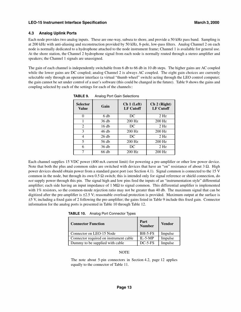
4.3 Analog Uplink Ports
Each node provides two analog inputs. These are one-way, subsea to shore, and provide a 50 kHz pass band. Sampling isat 200 kHz with anti-aliasing and reconstruction provided by 50 kHz, 8-pole, low-pass filters. Analog Channel 2 on eachnode is normally dedicated to a hydrophone attached to the node instrument frame; Channel 1 is available for general use.At the shore station, the Channel 2 hydrophone signal from each node is normally routed through a stereo amplifier andspeakers; the Channel 1 signals are unassigned.
The gain of each channel is independently switchable from 6 db to 66 db in 10 db steps. The higher gains are AC coupledwhile the lower gains are DC coupled; analog Channel 2 is always AC coupled. The eight gain choices are currentlyselectable only through an operator interface (a virtual “thumb wheel” switch) acting through the LEO control computer;the gain cannot be set under control of a user’s software (this could be changed in the future). Table 9 shows the gains andcoupling selected by each of the settings for each of the channels::
Each channel supplies 15 VDC power (400 mA current limit) for powering a pre-amplifier or other low power device.Note that both the plus and common sides are switched with devices that have an “on” resistance of about 3 Ω. Highpower devices should obtain power from a standard guest port (see Section 4.1). Signal common is connected to the 15 Vcommon in the node, but through its own 0.5 Ω switch; this is intended only for signal reference or shield connection, donot supply power through this pin. The signal high and low pins feed the inputs of an “instrumentation style” differentialamplifier; each side having an input impedance of 1 MΩ to signal common. This differential amplifier is implementedwith 1% resistors, so the common-mode rejection ratio may not be greater than 40 db. The maximum signal that can bedigitized after the pre-amplifier is ±2.5 V; reasonable overload protection is provided. Maximum output at the surface is±5 V, including a fixed gain of 2 following the pre-amplifier; the gains listed in Table 9 include this fixed gain. Connectorinformation for the analog ports is presented in Table 10 through Table 12.
NOTE
The note about 5-pin connectors in Section 4.2, page 12 appliesequally to the connector of Table 11.
TABLE 9. Analog Port Gain Selections
SelectorValue Gain Ch 1 (Left)
LF CutoffCh 2 (Right)
LF Cutoff
0 6 db DC 2 Hz1 36 db 200 Hz 200 Hz2 16 db DC 2 Hz3 46 db 200 Hz 200 Hz4 26 db DC 2 Hz5 56 db 200 Hz 200 Hz6 36 db DC 2 Hz7 66 db 200 Hz 200 Hz
TABLE 10. Analog Port Connector Types
Connector Function PartNumber Vendor
Connector on LEO-15 Node BH-5-FS ImpulseConnector required on instrument cable IL-5-MP ImpulseDummy to be supplied with cable DC-5-FS Impulse
Page 13
LEO-15 Instrument Interface Specification March 3, 2000
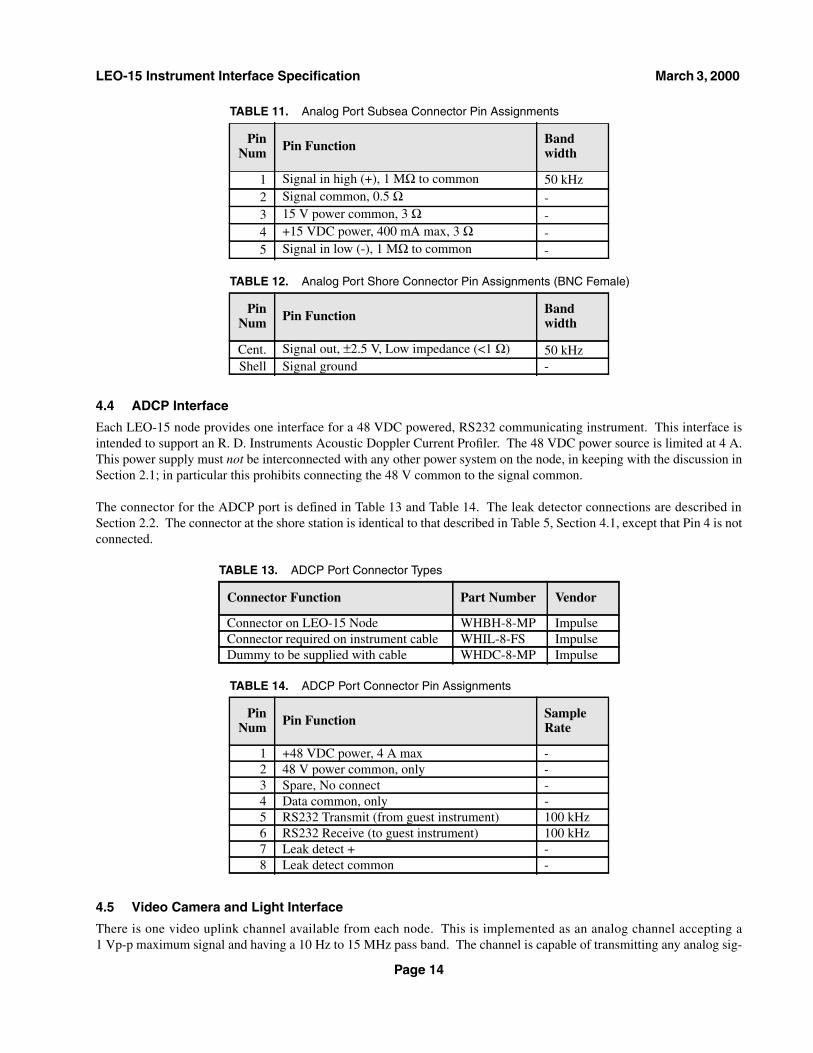
4.4 ADCP Interface
Each LEO-15 node provides one interface for a 48 VDC powered, RS232 communicating instrument. This interface isintended to support an R. D. Instruments Acoustic Doppler Current Profiler. The 48 VDC power source is limited at 4 A.This power supply must not be interconnected with any other power system on the node, in keeping with the discussion inSection 2.1; in particular this prohibits connecting the 48 V common to the signal common.
The connector for the ADCP port is defined in Table 13 and Table 14. The leak detector connections are described inSection 2.2. The connector at the shore station is identical to that described in Table 5, Section 4.1, except that Pin 4 is notconnected.
4.5 Video Camera and Light Interface
There is one video uplink channel available from each node. This is implemented as an analog channel accepting a1 Vp-p maximum signal and having a 10 Hz to 15 MHz pass band. The channel is capable of transmitting any analog sig-
TABLE 11. Analog Port Subsea Connector Pin Assignments
PinNum Pin Function Band
width
1 Signal in high (+), 1 MΩ to common 50 kHz2 Signal common, 0.5 Ω -3 15 V power common, 3 Ω -4 +15 VDC power, 400 mA max, 3 Ω -5 Signal in low (-), 1 MΩ to common -
TABLE 12. Analog Port Shore Connector Pin Assignments (BNC Female)
PinNum Pin Function Band
width
Cent. Signal out, ±2.5 V, Low impedance (<1 Ω) 50 kHzShell Signal ground -
TABLE 13. ADCP Port Connector Types
Connector Function Part Number Vendor
Connector on LEO-15 Node WHBH-8-MP ImpulseConnector required on instrument cable WHIL-8-FS ImpulseDummy to be supplied with cable WHDC-8-MP Impulse
TABLE 14. ADCP Port Connector Pin Assignments
PinNum Pin Function Sample
Rate
1 +48 VDC power, 4 A max -2 48 V power common, only -3 Spare, No connect -4 Data common, only -5 RS232 Transmit (from guest instrument) 100 kHz6 RS232 Receive (to guest instrument) 100 kHz7 Leak detect + -8 Leak detect common -
Page 14

LEO-15 Instrument Interface Specification March 3, 2000
nal with these characteristics, including any of the common single channel video formats: NTSC, PAL, SEACAM, etc.However, all the shore equipment, down stream of the receiver, is NTSC. Thus to use the monitors or recorder, the videosource must transmit NTSC.
Each node has switches currently arranged so that either the video camera port or the “REMUS” port (see Section 4.6) isattached to the video channel. If both are turned on by the LEO control computer, the video signals from each source willbe connected together; this is not recommended but is probably not harmful. The video camera port is normally con-nected to a pan and tilt camera permanently installed at one node, while this port should be available at the other node.The REMUS port is reserved for installation of the REMUS docking node, but may be available for other uses.
In addition to the video input path, the video camera connector on the node provides 15 VDC power and RS422 bi-direc-tional communications for controlling a camera or other video device. Like the guest ports, one should avoid drawing thefull 5 A permitted from the connector. The RS422/485 data connections are configured exactly as described inSection 4.1, paragraph 2 and paragraph 3; the shore communications connector is identical to that described in Table 5.Details of the node connector are given in Table 15 and Table 16.
Wiring to the video signal pins should be with 75 Ω coaxial conductors. Because the video common is connected to thepower and data commons in the node, care should be taken to avoid excessive and/or variable voltage drop in the videocommon conductor due to the power current. It is recommended that the power be routed to the camera on separate con-ductors from the video common, and that an isolating DC/DC converter be used at the camera to prevent power supplycurrent from flowing in the video signal common.
120VDC power for lights is provided on an additional connector. See Section 4.1, page 9 for information about voltagestability of the 120 V source. The light connector is detailed in Table 17 and Table 18.
4.6 REMUS Docking Node Interface
Each node provides a connection for a REMUS docking node. REMUS is a small, autonomous vehicle that will provideperiodic reconnaissance near the LEO-15 site. After each mission it will dock to recharge and unload data. The interfacedescribed in this section is reserved for connection of the dock, but is included for completeness because it may be avail-able for general use in some circumstances.
TABLE 15. Video Camera Port Connector Types
Connector Function PartNumber Vendor
Connector on LEO-15 Node BH-8-MP ImpulseConnector required on instrument cable IL-8-FS ImpulseDummy to be supplied with cable DC-8-MP Impulse
TABLE 16. Video Camera Port Connector Pin Assignments
PinNum Pin Function Sample
Rate
1 +15 VDC power, 5 A max -2 Data and 15 V power common -3 RS422/485 TX + (A) (from guest instrument) 200 kHz4 RS422/485 TX - (B) (from guest instrument) 200 kHz5 RS422/485 RX + (A) (to guest instrument) 200 kHz6 RS422/485 RX - (B) (to guest instrument) 200 kHz7 Video signal, 1 Vp-p max, 75 Ω, 15 MHz -8 Video common -
Page 15

LEO-15 Instrument Interface Specification March 3, 2000
The REMUS port is configured similarly to a guest port (Section 4.1) with two exceptions: the RS422 connection is con-nected to a high speed data channel, and the coaxial wires are routed to the video transmitter, not to a TTL device. All dis-cussion in Section 4.1 applies to this port except as noted below. The REMUS connectors are described in Table 19through Table 22.
The RS232 data connection is configured exactly as described in Section 4.1, paragraph 1; the shore communications con-nector is identical to that described in Table 5, except that Pin 4 has no effect on the signals at the node. The RS422 data
TABLE 17. Light Port Connector Types
Connector Function PartNumber Vendor
Connector on LEO-15 Node BH-2-FS ImpulseConnector required on instrument cable IL-2-MP ImpulseDummy to be supplied with cable DC-2-FS Impulse
TABLE 18. Light Port Connector Pin Assignments
PinNum Pin Function Sample
Rate
1 +120 VDC power, 5 A max -2 120 V power common -
TABLE 19. REMUS Dock Main Connector Types
Connector Function PartNumber Vendor
Connector on LEO-15 Node BH-8-FS ImpulseConnector required on instrument cable IL-8-MP ImpulseDummy to be supplied with cable DC-8-FS Impulse
TABLE 20. REMUS Dock Main Connector Pin Assignments
PinNum Pin Function Sample
Rate
1 RS232 Transmit (from dock controller) 200 kHz2 RS232 Receive (to dock controller) 200 kHz3 Data and 15 V power common -4 +15 VDC power, 5 A max -5 RS422 TX + (A) (from REMUS vehicle) 10 MHz6 RS422 TX - (B) (from REMUS vehicle) 10 MHz7 RS422 RX + (A) (to REMUS vehicle) 10 MHz8 RS422 RX - (B) (to REMUS vehicle) 10 MHz
TABLE 21. REMUS Dock Auxiliary Connector Types
Connector Function PartNumber Vendor
Connector on LEO-15 Node BH-6-FS ImpulseConnector required on instrument cable IL-6-MP ImpulseDummy to be supplied with cable DC-6-FS Impulse
Page 16

LEO-15 Instrument Interface Specification March 3, 2000
pins operate exactly as described in Section 4.2; the shore connector for this port is as described in Table 8. The discus-sion of video signals in Section 4.5 applies equally to the REMUS video input.
5.0 Guest Port Simulator
A guest port simulator is available to aid in testing an instrument for compatibility with the LEO-15 nodes. Two copies ofthe simulator presently exist; one will is likely to remain at the LEO site in Tuckerton, NJ, while the other may be avail-able for loan. Arrangements to use either simulator may be made with Rutgers University Marine Field Station.
Each simulator provides most of the functions of the guest port main and auxiliary connectors, as described inSection 4.1. In particular, the simulator provides 15 V power, RS-232 and RS422/485 data transmission, TTL up anddown links, leak and ground detection, surface and subsea connectors matching those on the LEO system, and switchingof all signals. A switching path for 120 V power is provided, but for instruments requiring 120 V power, the simulatormust be connected to an external 120 VDC power supply. While the simulator duplicates the functions of the LEO-15node leak and ground detectors, these tests are selected manually with front panel switches, rather than by automatedsequencing as on the actual node. Note that the simulator provides only the functions of a standard guest port and not anyof the other specialized interfaces discussed in Section 4.0. In particular, no simulation of the high speed ports isprovided.
5.1 Simulator Functions
Figure 8 shows a simplified diagram of the simulator. Serial telemetry signals are passed from the female 25-pin D-con-nector, through logic that simulates the telemetry system, through electronic switches of the type used to disconnect guestinstruments at the nodes, and finally to the guest port main connector. The sample/isolation logic provides the same logicshown in Figure 7, using the same driver chips as used in the nodes and surface telemetry boxes. In addition, flip-flopsclocked at 200 kHz mimic the sampling performed by the fiber-optic telemetry system, and optical isolators provide thegalvanic isolation that is inherent in the optical fiber path. The optical propagation delay of the 9 km fiber is not dupli-cated in the simulator.
The TTL signal path from the female BNC connectors to the guest port auxiliary connector is similarly isolated and sam-pled, in this case at 100 kHz. The TTL path is either an uplink or down link, depending on whether the guest port beingsimulated is an even or odd numbered port; a front-panel switch is provided to select the desired mode.
15 VDC power is supplied to the guest instrument from an AC-line powered supply of the same type and rating as thatused in the nodes. The power is passed through a copy of the current limited switch described in Section 2.3 to faithfullysimulate the ability of the node to start and run the instrument. The only aspect of the 15V power delivery that is not real-istic is the lack of other instruments sharing the output of the supply.
TABLE 22. REMUS Dock Auxiliary Connector Pin Assignments
PinNum Pin Function Bandwidth
1 Video signal, 1 Vp-p max, 75 Ω 15 MHz2 Video common -3 Leak detect + -4 Leak detect common -5 120 V common -6 +120 VDC power, 5 A max -
Page 17

LEO-15 Instrument Interface Specification March 3, 2000
D C B
1MA
+-
GROUND/LEAK
15V+
15V-
120V+
120V-
LEAK
15K
120K
POWER
15V DC
-+13A
AC POWER
G N D
SAMPLE/ISOLATE
GUEST PORT LOGIC
E N A
C O M
1 32 5
1 22 4
1 12 3
1 02 2
92 1
82 0
71 9
61 8
51 7
41 6
31 5
21 4
1
J6
RS-232
DB25S
200KHZ
100KHZ
SAMPLE/ISOLATE
G N D
G N D
J8
TTL UP
BNC-F
(OUTPUT)
EVEN
J7
TTL DOWN
BNC-F
(INPUT)
ODD
+5K
12W
J4
15K
120K
GROUND
TEST
LEAD
METER SELECT
J3
+-
+-
60K
12V DC
+ -
NORM
2800uF
200V
120V INPUT
-J5
5A
G N D
G N D
RS-422
RS-232
15V
TTL
120V
ODD
EVEN
GUEST TTL
SELECT
TTL
SIGNAL COMMON
RS-232
RS-422
++
--
5A
MAIN
12
34
56
78
J1
BH-8-FS
MASTER
12
34
56
J2
BH-6-FS
LEAK CONTINUITY
AUX
FIGURE 8. LEO-15 Guest Port Simulator, Block Diagram
Page 18

LEO-15 Instrument Interface Specification March 3, 2000
NOTE
The 15 V minus, and the signal grounds for the RS-232, RS-422and TTL signals are tied together as a single common, as shown inFigure 8. This common is passed to the instrument through onehalf of the two-pole 15 V power switch and Pin 3 of the Main guestport connector.
120 VDC power is routed through the guest simulator and a current limited switch to the auxiliary connector. Because thetotal power that may be drawn by an instrument from the 120 V connection is 600 Watts, it is not practical to provide thissupply as part of the guest port simulator. Users that are building instruments that require 120 V power are expected tosupply their own DC power when using the simulator. Use of an external supply also facilitates testing instruments over athe range of voltages likely to be present at the node (see Section 4.1, page 9). See the CAUTION in Section 5.2.2,paragraph 2 regarding energy storage in the simulator.
The ground and leak detectors in the simulator are drawn explicitly in Figure 8 to avoid obscuring this importantfunction. Ground detection is provided by coupling a 1 mA meter with a selected current limiting resistor in seriesbetween a front-panel binding post and, alternately, each pole of each power source. The binding post must be connectedto the instrument frame or surrounding water as described in Section 5.2.2, paragraph 3, and the meter and selector switchare used to test for electrical leakage to ground. The water leak detector biases the leak probe contacts of the auxiliaryconnector with a 12 V, isolated source and current limiting resistor; a high-impedance amplifier scales the detector currentso that a short-circuit on the leak contacts produces a full scale reading on the meter. A front-panel switch reverses thedetector polarity to check for the existence of the required continuity test diode located at the most distant point in the leakdetection path of the instrument (see Section 2.2 and Section 5.2.2, paragraph 11).
5.2 Simulator Instructions
The front panel of the simulator is shown in Figure 9. Connectors are provided on the left side for the instrument undertest, and on the right side for the corresponding surface equipment. Binding posts are available for application of external120 VDC power, and for connection of a ground lead to the instrument under test (see Section 5.2.2, paragraph 3). Fivetoggle switches are provided on the front panel to individually enable the various power and signal paths to the instrument,as well as a master switch to turn on or off all instrument connections simultaneously. An additional toggle switch on theright side selects use of the up or down link mode of the TTL signal path. The meter and selection switches of the groundand leak detectors are located in the center of the panel. A rocker switch controls the internal power supply of thesimulator.
5.2.1 Quick Instructions
1. Turn off (down) the Master toggle switch and the Power rocker switch before attaching the simulator to a source of ACpower (see Section 5.2.2, paragraph 1 for specifications of the AC source).
2. If the instrument requires 120 V power, connect an external power supply to the 120 V input binding posts, being verycareful to observe the polarity and 150 V maximum, as printed on the panel. Turn on the external power supply, asneeded.
FIGURE 9. LEO-15 Guest Port Simulator, Front Panel
Page 19

LEO-15 Instrument Interface Specification March 3, 2000
3. Connect a ground lead from the “Ground Test Lead” binding post to the frame of the instrument under test, or to abody of seawater in which the instrument is immersed.
4. Connect the cable(s) of the instrument under test to the Main and/or Auxiliary Guest Port connectors on the left of thepanel.
5. Connect the surface equipment to the RS232 D-connector and/or the appropriate TTL BNC connector on the right ofthe panel.
6. On the left side of the panel, turn on (up) all of the five power/signal enable toggle switches, or the subset of these thatis required by the instrument.
7. If the TTL signal path is to be used, then on the right side of the panel select the desired uplink or downlink mode ofthe TTL path and be sure that the surface equipment is connected to the corresponding BNC connector.
8. Turn on the Power rocker switch, and the Master toggle switch to supply power and signal connections to the instru-ment.
9. Verify correct instrument operation and data flow, as required.
10.To ground test the instrument, select each of the left most four positions of the Meter Select switch and observe thatthere is no meter deflection in any switch position. Any reading greater than 10% of full scale will cause the instru-ment to be rejected by the node (see additional comments in Section 5.2.2, paragraph 10).
11. If the instrument contains a leak probe, select the right most position of the Meter Select switch, with the Leak selecttoggle switch in the “Norm” position, and observe that there is no deflection of the meter. Change the Leak selectswitch to the “Continuity” position and observe a nearly full scale deflection of the meter, indicating that the leak con-tinuity test diode is present in the instrument and installed in the correct polarity.
12.The five individual power/signal select switches may be used to verify that the instrument is insensitive to the sequencein which the power/signal paths are enabled, and to aid in diagnosing ground faults.
13. If the instrument uses 120 V power, vary the voltage of the external supply from 90 VDC to 135 VDC to verify correctoperation of the instrument over the range of possible voltages at the LEO nodes.
5.2.2 Detailed InstructionsThis section provides more information for each of the steps listed in Section 5.2.1.
1. The simulator can be powered from any AC source having a voltage in the range of 90-132 VAC or 180-264 VAC;range switching is automatic and does not require any operator action. The simulator is fused with a Bussman ABC-3,1-1/4x1/4 inch, 3 A fuse, suitable for use on 120 VAC mains in North America; for use on 230 VAC mains, the fusecan be replaced with a Bussman GDA-1.6, 5x20 mm, 1.6 A fuse, requiring an alternate fuse holder knob (Littelfuse3455LS1-20). An IEC 320 power inlet is supplied on the back of the simulator for connection to the AC mains. It isrecommended to turn off (down) the Master toggle switch and the Power rocker switch before attaching the simulatorto the AC mains.
2. An external 120 VDC supply must be attached to the simulator if the instrument requires 120 V power. Connect thesupply to the 120 V input binding posts on the front panel, being very careful to observe the polarity and 150 Vmaximum. There is no internal protection against improper polarity or voltage and considerable damage can be doneto the simulator and instrument under test from failure to connect the power supply correctly. If the Master switch onthe simulator is off, the external supply can be turned on without applying power to the instrument, because the inter-nal switch will keep instrument power off. For off-site testing, the user is expected to provide their own power supply;a suitable supply is usually available at the Rutgers University Marine Field Station in Tuckerton, NJ when testing atthe LEO shore station.
CAUTION
The simulator contains a 2800 µF capacitor on the 120 V bus tomodel the impedance of the 120 V supply in the nodes. The user iscautioned that disconnecting or turning off the external 120 Vsupply may not immediately remove power from the instrumentattached to the simulator; time must be allowed for the capacitance
Page 20

LEO-15 Instrument Interface Specification March 3, 2000
of the simulator and power supply to discharge to safe levels. Thebleeder resistor in the simulator provides a time constant of14 seconds for the internal capacitor; the power supply will haveadditional components. Several time constants are required toreach a safe voltage. However, turning off the instrument powerwith the Master or 120 V switches on the simulator will removepower promptly.
3. In order to test for ground faults, there must be an electrical path from any point of potential leakage back to theground detector in the simulator. For this purpose, a ground lead must be connected from the “Ground Test Lead”binding post to the instrument under test. At a minimum, the ground lead must be attached to the metal frame or hous-ing of the instrument (if any); this will detect any inadvertent connections of the instrument’s electrical wiring to itsframe. However, it is far better to immerse the instrument and all of its cables, connectors and splices in a container ofseawater (or the sea itself) and to immerse the bare end of the ground lead from the simulator in the same water; thiswill test for leakage from all cables, connectors, and instrument probes that might be leaking or grounded. The ends ofthe cables that will eventually connect to the guest connectors of the node can be included in the test if they connect tothe simulator by way of some extensions (not supplied).
4. The left side of the panel has Guest Port Main and Auxiliary connectors identical to those on the nodes. These connec-tors are described in Table 1 through Table 4. Connect the cable(s) of the instrument under test to the Main and/orAuxiliary Guest Port connectors, as appropriate.
5. The right side of the panel has connectors identical to those on the Surface Telemetry Boxes. These connectors aredescribed in Table 5 and in the TTL signal description in Section 4.1, page 11. Connect the surface equipment for theinstrument under test to the RS232 D-connector and/or the appropriate TTL BNC connector (see paragraph 7, below).
6. As shown in Figure 8, each group of power and signal wires connected to the guest instrument has its own set of elec-tronic switches (one for each pole). Each group is enabled by a front-panel toggle switch, just as each group ofswitches in the actual nodes is enabled by a keyword in an initialization file. When the Master switch is turned on, allof the enabled functions are also turned on. Note that the Master switch directly controls the negative pole of the 15 Vpower switch because this pole is both the power and signal common; this pole must be closed if any or all of the 15 V,RS-232 and RS-422 signals are used. The only difference from the switching behavior of the actual node is that in thenode groups are turned on in an undefined (but consistent) sequence (generally with a fraction of a second betweengroups) when an instrument is powered up, rather than simultaneously as the simulator Master switch does. Often, thenodes are programmed (through the initialization file) to enable all the power and signal lines to a guest when it isturned on; but they can be configured to enable only those wires needed by a particular instrument, thus minimizingthe chance for a ground fault on a connector pin that is not even being used. The five group toggle switches on the leftside of the panel should be set as the node is expected to be configured, all on (up) being the general case.
7. Figure 8 shows that Pins 1 and 2 of the Guest Port Auxiliary connector can be attached to either of two different TTL(5 V logic) signal paths, one downlink from the surface to the instrument and one uplink from the instrument to thesurface. In the actual nodes, there is only one signal path to/from any guest port, but the odd numbered ports havedownlinks and the even numbered ports have uplinks. The Even/Odd select switch on the right side of the panel con-figures the simulator for the desired mode of operation. To use the TTL signal path, the selector must be in the correctposition and the signal to/from the surface equipment must be connected to the corresponding BNC connector.
8. Power for the simulator is controlled by the Power rocker switch in the middle of the panel. This switch provides the15 V guest power as well as the internal supplies required by the simulator logic. Power is not transmitted to theinstrument unless enabled by the left-side toggle switches. To apply power to the instrument and connect the signals,raise the Master toggle switch; remember that the Master switch directly controls the power signal common on Mainconnector, Pin 3, to this switch must be turned off to completely isolate the instrument under test.
9. Verify correct instrument operation and data flow, as required. ’Nuff said.
10.Ground tests can be performed using the Meter Select switch in the middle of the panel, when the simulator isgrounded to the instrument as described in paragraph 3, above. Each position of the switch connects one side of apower bus to the water or case surrounding the instrument, thus providing the bias needed to drive current through anyleakage path that may exist. Select each of the left most four positions of the Meter Select switch in turn and pause toobserve the meter reading.
Page 21

LEO-15 Instrument Interface Specification March 3, 2000
A number of important issues regarding interpretation ground readings are discussed below:
Any reading greater than 10% of full scale will cause the instrument to be rejected by the node. However, it must beremembered that all instruments and node components that are connected to a particular bus are tested together; thismeans that small amounts of leakage on several devices will add together. The node will declare a fault and start toturn instruments off when the total leakage exceeds 10% of full scale (which translates to 100 µA of actual leakagecurrent). Thus it is important that individual instruments have small leakage currents, preferably below 1% of fullscale; even a few percent indicates a fault that should be traced, as such faults tend to get worse with time.
The labels on the first four positions of the Meter Select switch indicate the side of the bus to which the ground meteris connected, not the side of the bus that may be faulted. If the minus side of the 15 V bus is faulted to seawater (imag-ine the Ground Test Lead, J3 in Figure 8, connected to Pin 3 of the Main guest connector, J1) and the select switch isin the “15V-” position, no leakage will be indicated; this occurs because there is no voltage bias to drive currentthrough the fault. However, if the “15V+” position is selected with the same fault, leakage current will flow, limited toa full scale reading by the 15,000 Ω resistor in series with the meter, but the 15 V minus bus is the one that is faulted.
Not all faults will produce a full scale reading. There are two principal causes of partial readings: high impedancefaults and faults to intermediate voltages. A “hard” (low impedance) fault to the side of a bus opposite to the oneselected for test (e.g. a ground on the 120 V positive bus when “120V-” is selected for the meter) will produce a fullscale reading. Typical hard faults occur if: a wiring “error” connects a circuit to the instrument case, water in a hous-ing touches electrical circuits, a connector floods, or a cable is severed. A “weak” (high impedance) fault has animpedance comparable to that of the series limiting resistor in the meter circuit (an impedance much less would pro-duce a hard fault, and an impedance much greater would produce no fault at all). Typical weak faults occur if: conden-sation or salt contamination exists on circuits, a pin hole or bonding failure in a cable or molded assembly allows watercontact, or dirt or scratches on rubber connectors prevent total sealing of pins.
Intermediate voltages exist in systems with more than one power supply connected to circuit common. Frequentlyinstruments will make 5 V from the 15 V supply provided by the node. Even a hard ground on such a supply will notproduce a full scale fault because the bias voltage is less than the voltage of the bus that is tested. Using the exampleof a 5 V supply that shares its negative pole with the negative of the 15 V, a hard ground on the 5 V positive would pro-duce a reading of 33% (5V/15V) when the “15V-” test is selected, and a reading of 67% (10V/15V) when the “15V+”test is selected. It is generally possible to distinguish a weak ground from a hard ground to an intermediate voltage bycomparing the readings from the plus and minus tests of any one bus: if the readings of the two tests add up to approx-imately 100%, then it is most likely that a hard fault to an intermediate voltage exists, rather than a combination ofweak faults. The expected voltage of the faulted bus can be determined from the ratio of the two readings.
It is not a good practice for an instrument to produce (with an internal power supply) a voltage that is higher than thevoltage of the power source and to connect the output of this supply back to the source. Any such higher voltage sup-ply and all circuits powered by it should be kept isolated from the source (see discussion of isolated instruments inSection 2.1, page 5). However, if a higher voltage is produced and is not isolated from the node power source, notethat a ground to this higher voltage can produce ground meter readings in excess of full scale.
The ground tester in the simulator is manually operated to scan the poles of the two available power buses. In theactual nodes, the ground tester is automatically sequenced through these tests with dwell times of 100’s of millisec-onds per test. This leads to the possibility that an instrument might pass the ground test on the simulator but fail on thenode due to excessive capacitance between the instrument ground and its case. In such a case, the capacitance toground charges when the test switch is changed and if the measurement is made too soon charging current may still beflowing and a false ground fault will be declared. Section 2.1, paragraph 3 gives some guidance on acceptable capaci-tance to ground for instruments.
11. Instruments may optionally contain a water leak probe to warn of water in a housing. Section 2.2 fully describes theleak probe function. The simulator can use its front panel meter to “read” the leak probe when the Meter Select switchis in the “Leak” position. An adjacent toggle switch selects either the normal leak test function or a reversed polaritycontinuity test that will show a near full scale deflection of the meter if there is a diode present in the leak circuit. Thisdiode should be installed at the electrically most distant point in the instrument’s leak detect system, so that all the wir-ing to that point can be verified.
12.As noted in paragraph 6, above, the sequence in which the power and signal switches for an instrument are turned onor off is undefined. The five individual power/signal select switches may be used to verify that the instrument is insen-sitive to the sequence in which it is powered up and down. These switches may also be useful in diagnosing ground
Page 22

LEO-15 Instrument Interface Specification March 3, 2000
faults, by showing which wires are faulted; however, because the signal common is controlled only by the Masterswitch, most grounds are unlikely to be isolated until the Master is turned off.
13.As noted in Section 4.1, page 9,the 120 V power at the nodes is unregulated and is sensitive to both utility variationsand power demand at the nodes. For an instrument that uses 120 V power, the voltage of the external supply can bevaried from 90 VDC to 135 VDC to simulate the range of possible voltages at the LEO nodes.
6.0 Change History
Rev 1.1 Original Release.
Rev 1.11 Updated Table 9 and related text.
Rev 1.12 Added contact info for mechanical information.
Rev 1.2 Added Figure 5,corrected Figure 7,added Section 5.0,corrected pin-outs listed in Table 7 and Table 11 and added
corresponding notes,added note about Kellums installation to Section 4.1, page 8,expanded ground fault discussion in Section 2.1,added RS422 polarity note in Section 4.1, page 11,added contact info for Rutgers Marine Field Station.
Rev 1.2.1 Added PDF versions of postscript figures to HTML document.
7.0 Contact Information
An HTML version of this document is available at:http://adcp.whoi.edu/LEO15/HARDWARE_DOC/leo_ports.html
For further information on the electrical topics discussed above, contact:
Ned C. ForresterWoods Hole Oceanographic InstitutionBigelow-302Water StreetWoods Hole, MA 02543
(508) 289-2226FAX: (508) 457-2104Internet: [email protected]
Page 23

LEO-15 Instrument Interface Specification March 3, 2000
For information about communicating with the LEO control computer, and/or a copy of WHOI/OSL document: 101392,“LEO-15 Software Interface Specification”, contact:
Roger P. StokeyWoods Hole Oceanographic InstitutionBigelow-301Water StreetWoods Hole, MA 02543
(508) 289-3323FAX: (508) 457-2104Internet: [email protected]
For information on the mechanical aspects of the LEO-15 nodes, contact:
Ben G. AllenWoods Hole Oceanographic InstitutionBigelow-308Water StreetWoods Hole, MA 02543
(508) 289-2930FAX: (508) 457-2104Internet: [email protected]
For information about installation of instruments on the LEO-15 nodes including boat and dive support, or about use ofequipment and facilities at the Marine Field Station in Tuckerton, NJ, contact:
Rose PetreccaDirector of Marine Ops/Sr. Marine ScientistRutgers University Marine Field Station800 Great Bay BoulevardTuckerton, NJ 08087
(609) 296-5260 ext. 238Internet: [email protected]
Page 24