Embed Size (px)
Citation preview
león cupra RTechnical insight No. 04

No part of this document may be reproduced or transmitted wholly or partially in any form or by any means, electronic or mechanical, including photocopying, recording or by any information storage or retrieval system without the prior written permission of the copyright holders.
TITLE: Leon Cupra RAUTHOR: Service OrganisationSEAT S.A. Sdad. Unipersonal. Zona Franca, Calle 2.Reg. Mer. Barcelona. Tomo 23662, Folio 1, Hoja 56855l
1st Edition
DATE OF PUBLICATION: March 2002LEGAL REGISTER: B. 45.246-2000Printing and typesetting: SYL, S.A. - Silici, 9-11Pol. Industrial Famades - 08940 Cornellá (Barcelona)
Technical Status: 02.02. Due to constant product development and improvements, the data which appears in this document is subject to possible modifications.
3
León Cupra R
BODYWORK 6
– Exterior design 6– Interior design 9– Seats 10
CONTENTS
THE CUPRA CONCEPT R 4
– Cupra R 4
DRIVETRAIN 11
– Front axle 11– Rear axle 12– Wheels 13– Brakes 13
POWERTRAIN 16
– 02M gearbox 16– Dual mass flywheel 16– 1.8 20VT turbo engine 17– Modifications 18
Note: The precise checking, adjustment and repair information is contained in the relevant
Repair Manuals.

4
The Cupra Concept R
CUPRA R
The new León Cupra R represents the best in sports driving for the SEAT Brand. Not only
does it surpass its predecessor, the León Cupra, but is also the most powerful front wheel
drive vehicle in the SEAT range.
When driving this vehicle, its sporty competitive handling is evident while at the same time
the driver and passengers can enjoy a high level of comfort.
These characteristics are further enhanced by the 1.8 20V turbo engine, delivering
154 kW and complying with the EU III emission legislation. The chassis is modified
and now includes the "agile chassis concept" previously fitted to the Ibiza 02
model.
The interior and exterior design has been completely
revised on this vehicle, improving the appearance,
without ignoring the functional aspects of the bodywork.
The "Seat Sport" department is responsible for fitting
certain parts on this vehicle, and also for the
final individualised quality control
check, ensuring that each vehicle
fully reflects the sporty
nature of the Brand.

5
The Cupra Concept R
AT04-01
This booklet will cover the new features and components launched on the León Cupra R.
6
Bodywork
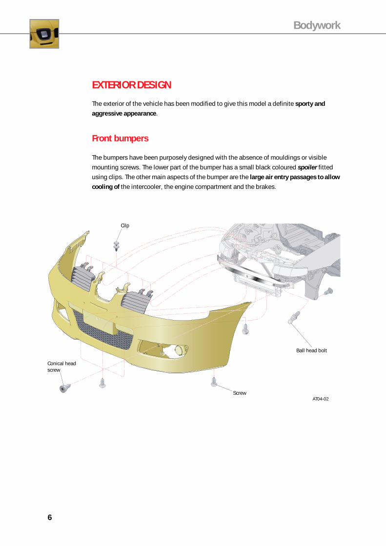
EXTERIOR DESIGN
The exterior of the vehicle has been modified to give this model a definite sporty and
aggressive appearance.
Front bumpers
The bumpers have been purposely designed with the absence of mouldings or visible
mounting screws. The lower part of the bumper has a small black coloured spoiler fitted
using clips. The other main aspects of the bumper are the large air entry passages to allow
cooling of the intercooler, the engine compartment and the brakes.
AT04-02
Ball head bolt
Screw
Cilp
Conical head screw
7
Bodywork
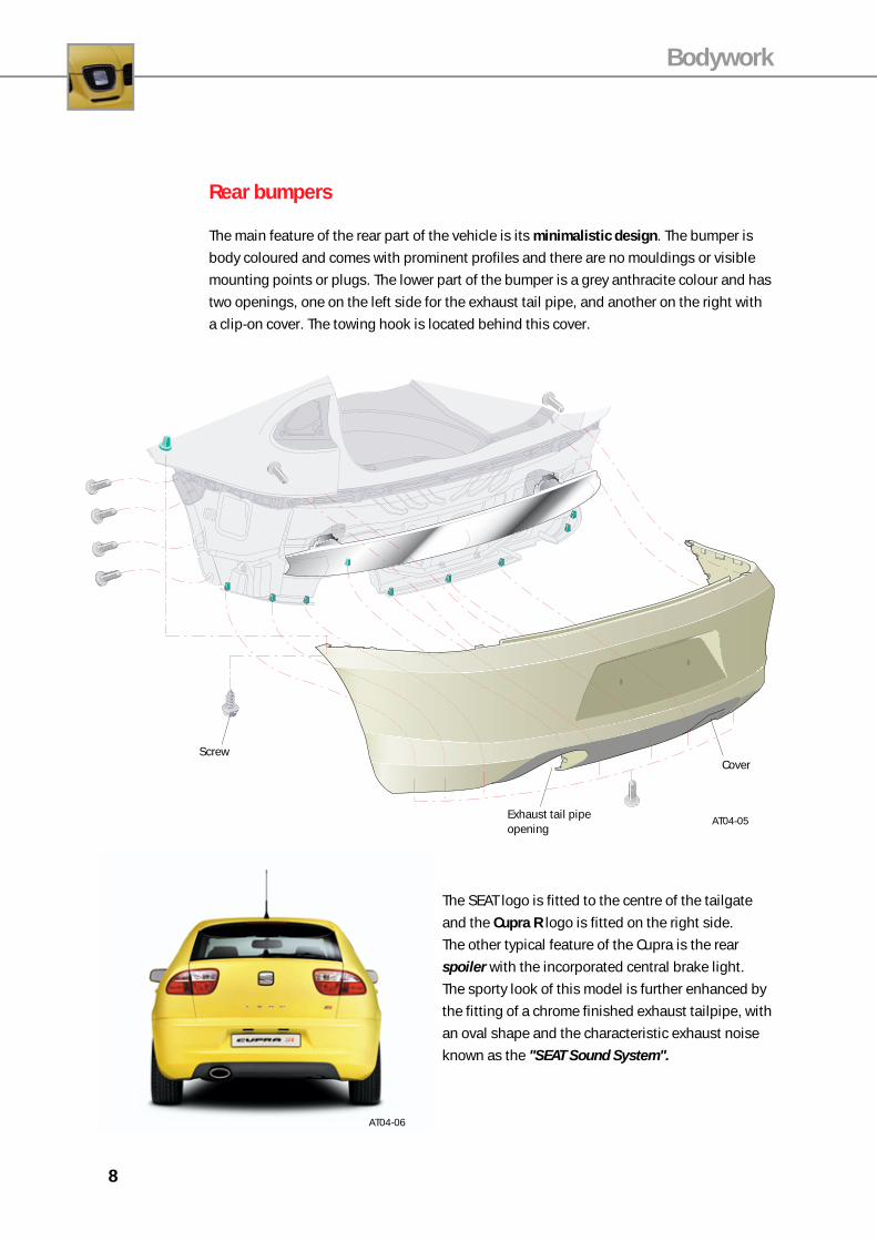
The lower side grilles cover the fog lights and are easy to remove, without the use of tools.
The opening for the screw fiexed type towing ring is located behind the right hand fog light
grille. The external temperature sensor for the instrument panel is located behind the left-
hand fog light grille. The fog lights have been redesigned and are smaller in size and
circular shaped.
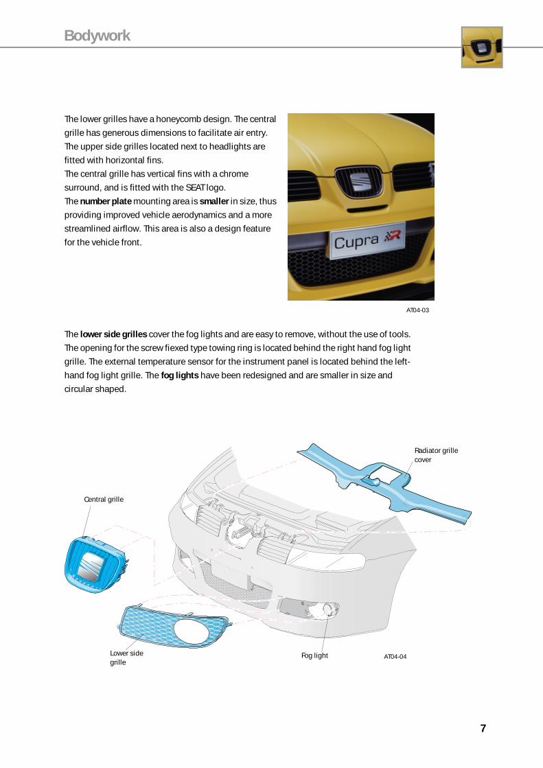
The lower grilles have a honeycomb design. The central
grille has generous dimensions to facilitate air entry.
The upper side grilles located next to headlights are
fitted with horizontal fins.
The central grille has vertical fins with a chrome
surround, and is fitted with the SEAT logo.
The number plate mounting area is smaller in size, thus
providing improved vehicle aerodynamics and a more
streamlined airflow. This area is also a design feature
for the vehicle front.
AT04-03
AT04-04Lower side grille
Fog light
Central grille
Radiator grille cover
8
Bodywork
The SEAT logo is fitted to the centre of the tailgate
and the Cupra R logo is fitted on the right side.
The other typical feature of the Cupra is the rear
spoiler with the incorporated central brake light.
The sporty look of this model is further enhanced by
the fitting of a chrome finished exhaust tailpipe, with
an oval shape and the characteristic exhaust noise
known as the "SEAT Sound System".
AT04-06
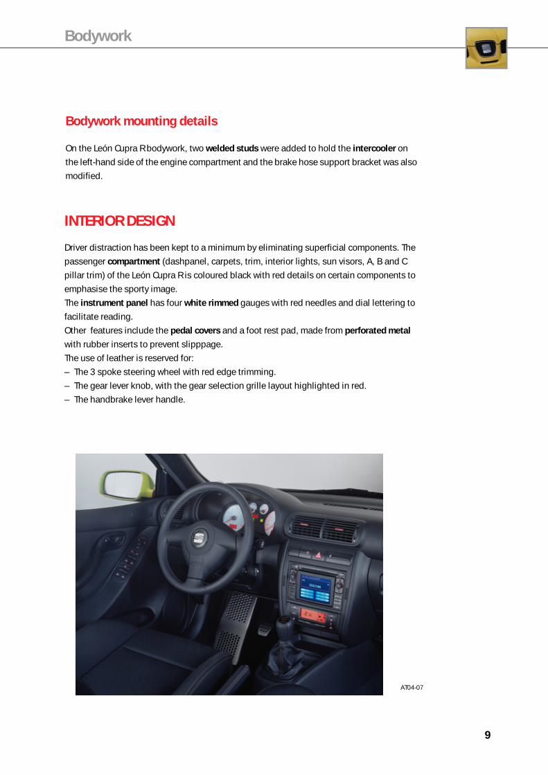
Rear bumpers
The main feature of the rear part of the vehicle is its minimalistic design. The bumper is
body coloured and comes with prominent profiles and there are no mouldings or visible
mounting points or plugs. The lower part of the bumper is a grey anthracite colour and has
two openings, one on the left side for the exhaust tail pipe, and another on the right with
a clip-on cover. The towing hook is located behind this cover.
AT04-05
Screw
Exhaust tail pipe opening
Cover
9
Bodywork
INTERIOR DESIGN
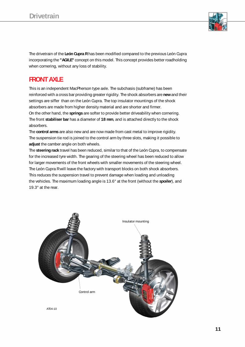
Driver distraction has been kept to a minimum by eliminating superficial components. The
passenger compartment (dashpanel, carpets, trim, interior lights, sun visors, A, B and C
pillar trim) of the León Cupra R is coloured black with red details on certain components to
emphasise the sporty image.
The instrument panel has four white rimmed gauges with red needles and dial lettering to
facilitate reading.
Other features include the pedal covers and a foot rest pad, made from perforated metal
with rubber inserts to prevent slipppage.
The use of leather is reserved for:
– The 3 spoke steering wheel with red edge trimming.
– The gear lever knob, with the gear selection grille layout highlighted in red.
– The handbrake lever handle.
Bodywork mounting details
On the León Cupra R bodywork, two welded studs were added to hold the intercooler on
the left-hand side of the engine compartment and the brake hose support bracket was also
modified.
AT04-07

10
SEATSThe León Cupra R can be fitted with two different types of front seat, sporty or recaro. Both
versions are fitted with side airbags.
Both are black in colour with red stitching and the R logo is highlighted in the centre of the
backrest. On the Recaro version, the R logo is located above the Recaro symbol.
AT04-08
The rear seats are also black with red borders. Two combinations are available to match the
fitting of Sporty or Recaro seats on the front.
With the sporty seats, the rear seating is divided asymmetrically giving 3 sitting positions
and three headrests. The backrest is split unequally (2+1).
On models fitted with the Recaro type seats, two seating positions are available at the rear
with two corresponding headrests. These are bucket type seats and the backrest is not
split on this model.
Bodywork
AT04-09
11
The drivetrain of the León Cupra R has been modified compared to the previous León Cupra
incorporating the "AGILE” concept on this model. This concept provides better roadholding
when cornering, without any loss of stability.
FRONT AXLEThis is an independent MacPherson type axle. The subchasis (subframe) has been
reinforced with a cross bar providing greater rigidity. The shock absorbers are new and their
settings are siffer than on the León Cupra. The top insulator mountings of the shock
absorbers are made from higher density material and are shorter and firmer.
On the other hand, the springs are softer to provide better driveability when cornering.
The front stabiliser bar has a diameter of 18 mm, and is attached directly to the shock
absorbers.
The control arms are also new and are now made from cast metal to improve rigidity.
The suspension tie rod is joined to the control arm by three slots, making it possible to
adjust the camber angle on both wheels.
The steering rack travel has been reduced, similar to that of the León Cupra, to compensate
for the increased tyre width. The gearing of the steering wheel has been reduced to allow
for larger movements of the front wheels with smaller movements of the steering wheel.
The León Cupra R will leave the factory with transport blocks on both shock absorbers.
This reduces the suspension travel to prevent damage when loading and unloading
the vehicles. The maximum loading angle is 13.6° at the front (without the spoiler), and
19.3° at the rear.
Drivetrain
AT04-10
Insulator mounting
Control arm
12
Drivetrain
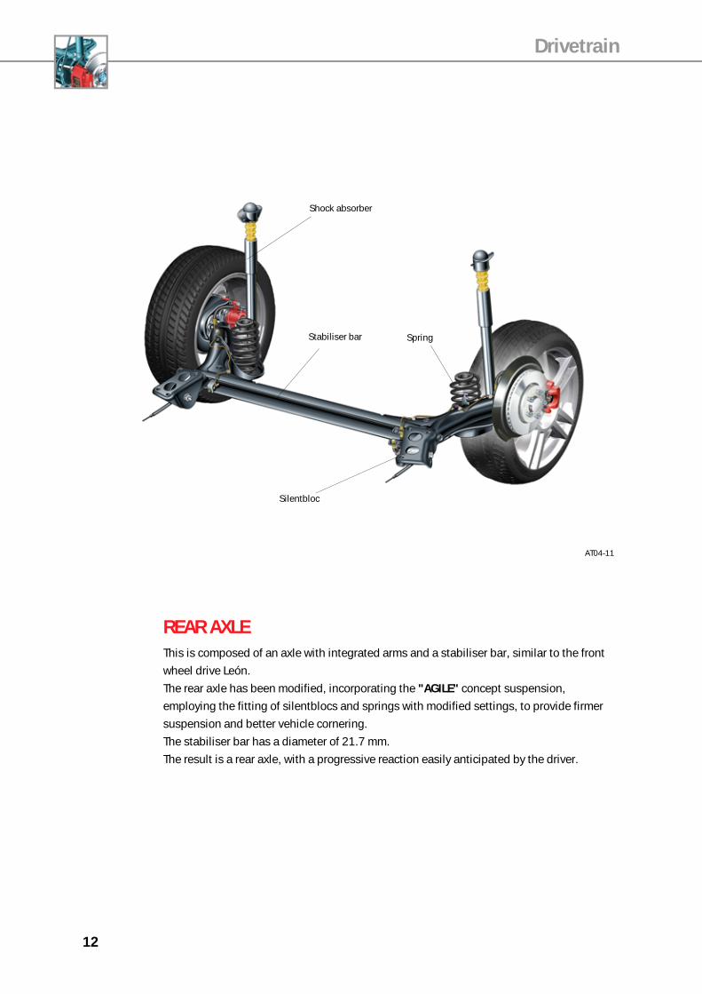
AT04-11
Silentbloc
Stabiliser bar
Shock absorber
Spring
REAR AXLEThis is composed of an axle with integrated arms and a stabiliser bar, similar to the front
wheel drive León.
The rear axle has been modified, incorporating the "AGILE" concept suspension,
employing the fitting of silentblocs and springs with modified settings, to provide firmer
suspension and better vehicle cornering.
The stabiliser bar has a diameter of 21.7 mm.
The result is a rear axle, with a progressive reaction easily anticipated by the driver.
13
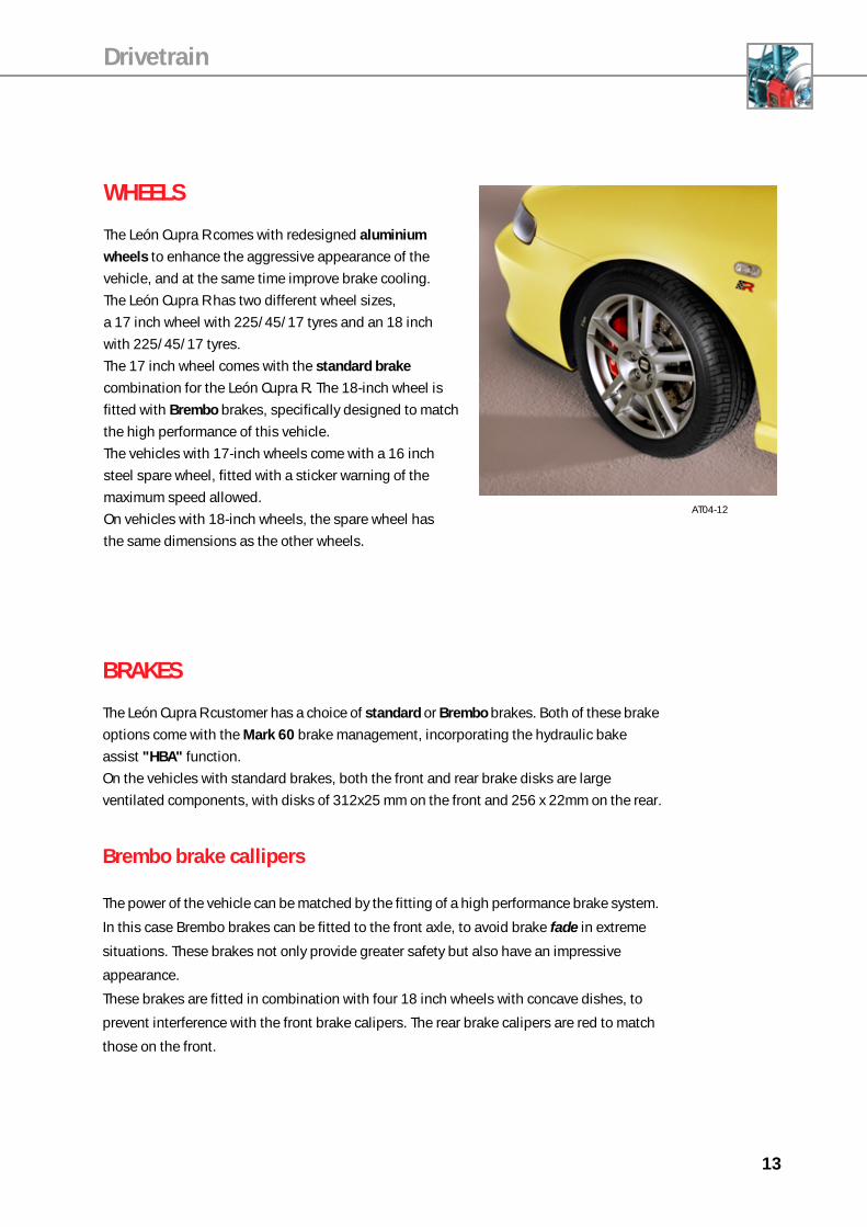
WHEELS
The León Cupra R comes with redesigned aluminium
wheels to enhance the aggressive appearance of the
vehicle, and at the same time improve brake cooling.
The León Cupra R has two different wheel sizes,
a 17 inch wheel with 225/45/17 tyres and an 18 inch
with 225/45/17 tyres.
The 17 inch wheel comes with the standard brake
combination for the León Cupra R. The 18-inch wheel is
fitted with Brembo brakes, specifically designed to match
the high performance of this vehicle.
The vehicles with 17-inch wheels come with a 16 inch
steel spare wheel, fitted with a sticker warning of the
maximum speed allowed.
On vehicles with 18-inch wheels, the spare wheel has
the same dimensions as the other wheels.
AT04-12
Drivetrain
BRAKES
The León Cupra R customer has a choice of standard or Brembo brakes. Both of these brake
options come with the Mark 60 brake management, incorporating the hydraulic bake
assist "HBA" function.
On the vehicles with standard brakes, both the front and rear brake disks are large
ventilated components, with disks of 312x25 mm on the front and 256 x 22mm on the rear.
Brembo brake callipers
The power of the vehicle can be matched by the fitting of a high performance brake system.
In this case Brembo brakes can be fitted to the front axle, to avoid brake fade in extreme
situations. These brakes not only provide greater safety but also have an impressive
appearance.
These brakes are fitted in combination with four 18 inch wheels with concave dishes, to
prevent interference with the front brake calipers. The rear brake calipers are red to match
those on the front.
14
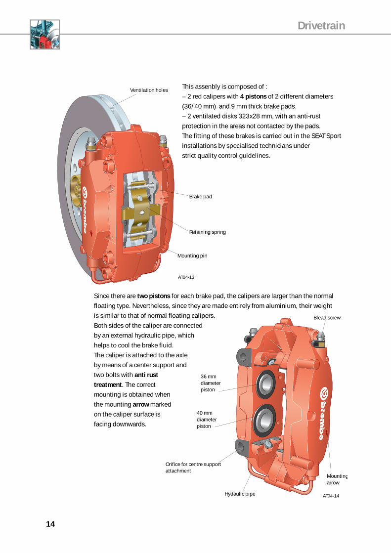
36 mm diameter piston
Blead screw
Mountingarrow
40 mm diameter piston
Hydaulic pipe AT04-14
Orifice for centre support attachment
This assenbly is composed of :
– 2 red calipers with 4 pistons of 2 different diameters
(36/40 mm) and 9 mm thick brake pads.
– 2 ventilated disks 323x28 mm, with an anti-rust
protection in the areas not contacted by the pads.
The fitting of these brakes is carried out in the SEAT Sport
installations by specialised technicians under
strict quality control guidelines.
AT04-13
Drivetrain
Ventilation holes
Brake pad
Retaining spring
Mounting pin
Since there are two pistons for each brake pad, the calipers are larger than the normal
floating type. Nevertheless, since they are made entirely from aluminium, their weight
is similar to that of normal floating calipers.
Both sides of the caliper are connected
by an external hydraulic pipe, which
helps to cool the brake fluid.
The caliper is attached to the axle
by means of a center support and
two bolts with anti rust
treatment. The correct
mounting is obtained when
the mounting arrow marked
on the caliper surface is
facing downwards.

15
Drivetrain
Nota: Para más información sobre la gestión de frenos Mark 60 consulte el cuaderno di-dáctico No. XX
ABS
rpmx1000 km/h
Hydraulic unit N55
Combination sensor G200-202
Brake pedal switch F
Braking pressure sensor G201-214
Wheel speed sensorsG44-45-46-47
ABS/ESP control unit J104
Hydraulic pump V64
ESP button E256
Steering wheel angle sender G85
Engine control unit J220
ESP warning lightK155
ABS warning lightK47
Hanbrake warning light K14
AT04-15Instrument panel J285
Note: For more information, consult the Self Study Program No. 74 and No. 85.
Brake management
The León Cupra R comes with Mark 60 brakes incorporating ABS+TCS+ESP and the
hydraulic brake assist “HBA” function.
The main difference in relation to previous Mark 60 systems is that the brake pump is fitted
with two pressure senders (G201-G214) for improved safety.
It should also be pointed out that the ESP switch enables this function to be turned off by
the driver. In extreme conditions, the ESP will come on, even it had been switched off.
The flashing ESP warning light on the instrument panel will indicate the automatic
activation of the ESP.
16
Powertrain
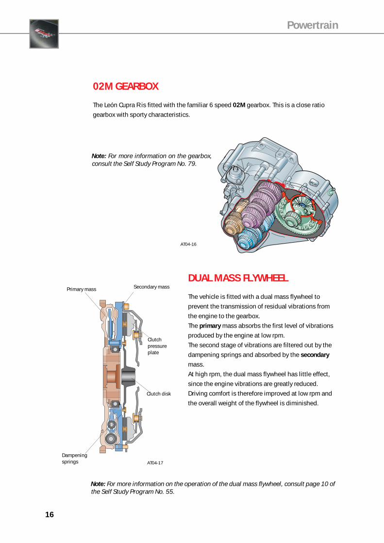
02M GEARBOX
The León Cupra R is fitted with the familiar 6 speed 02M gearbox. This is a close ratio
gearbox with sporty characteristics.
DUAL MASS FLYWHEEL
The vehicle is fitted with a dual mass flywheel to
prevent the transmission of residual vibrations from
the engine to the gearbox.
The primary mass absorbs the first level of vibrations
produced by the engine at low rpm.
The second stage of vibrations are filtered out by the
dampening springs and absorbed by the secondary
mass.
At high rpm, the dual mass flywheel has little effect,
since the engine vibrations are greatly reduced.
Driving comfort is therefore improved at low rpm and
the overall weight of the flywheel is diminished.
AT04-16
Primary mass Secondary mass
Clutch pressure plate
Dampening springs
Clutch disk
AT04-17
Note: For more information on the gearbox,consult the Self Study Program No. 79.
Note: For more information on the operation of the dual mass flywheel, consult page 10 ofthe Self Study Program No. 55.

17
Pow
er
Torq
ue
Technical specifications
Designation letters ......................................AMK
Capacity ............................................ 1,781 cm3
Bore x Stroke ................................... 81.0 x 86.4
Compression ratio ..................................... 9.5:1
Maximum torque .................... 270 Nm between
2,100 and 5,000 rpm
Maximum power .............. 154 kW at 5,800 rpm
Ignition and
injection system ............ Bosch Motronic ME 7.5
Emission legislation .................................. EU III
Fuel octane rating ............. 98 Octane minimum
Note: 95 octane petrol can be used, however in this
case maximum power will not be available. AT04-19
1.8 20VT TURBO ENGINE
The 1.8 20VT engine was modified to provide a power output of 154 kW. The modifications
consist of the incorporation of new components on the engine management system and the
development of a new programme for the engine control unit.
AT04-18
Powertrain

18
Powertrain
MODIFICATIONS
Modifications have been to this engine compared to previous 1.8 20VT engines, to
guarantee its durability while at the same providing a power output of 154 kW.
The oil injectors in the lubrication circuit have an increased flow for piston cooling, and
the pistons have also been modified exclusively for this engine.
The exhaust is larger in size and offers better temperature resistance.
The air enters the inlet manifold on the left side from the intercooler which is located
on that side.
The new features on the turbo, intercooler and exhaust will be explained in detail in the
section dealing with engine management.
Turbo
This has been designed exclusively for this engine and is capable of providing a boost
pressure of up to 2.1 bars. The turbine blades have a diameter of 50 mm. The turbine is
fitted on a 4 mm diameter shaft. The cooling and lubricating passages are also larger than
on the engines with less horsepower.
The exhaust turbine contains the exhaust gas temperature sensor (G235).
Oil entry
Coolant entry
Exhaust gas temperature sensor G235
AT04-20
19
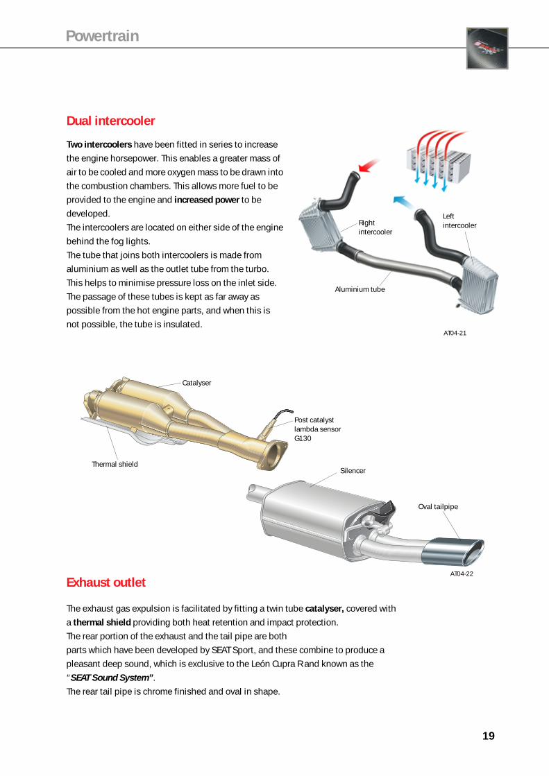
Dual intercooler
Two intercoolers have been fitted in series to increase
the engine horsepower. This enables a greater mass of
air to be cooled and more oxygen mass to be drawn into
the combustion chambers. This allows more fuel to be
provided to the engine and increased power to be
developed.
The intercoolers are located on either side of the engine
behind the fog lights.
The tube that joins both intercoolers is made from
aluminium as well as the outlet tube from the turbo.
This helps to minimise pressure loss on the inlet side.
The passage of these tubes is kept as far away as
possible from the hot engine parts, and when this is
not possible, the tube is insulated.
Powertrain
Exhaust outlet
The exhaust gas expulsion is facilitated by fitting a twin tube catalyser, covered with
a thermal shield providing both heat retention and impact protection.
The rear portion of the exhaust and the tail pipe are both
parts which have been developed by SEAT Sport, and these combine to produce a
pleasant deep sound, which is exclusive to the León Cupra R and known as the
“SEAT Sound System”.
The rear tail pipe is chrome finished and oval in shape.
AT04-21
Left intercoolerRight
intercooler
Aluminium tube
Catalyser
Post catalyst lambda sensor G130
Silencer
Oval tailpipe
Thermal shield
AT04-22
20
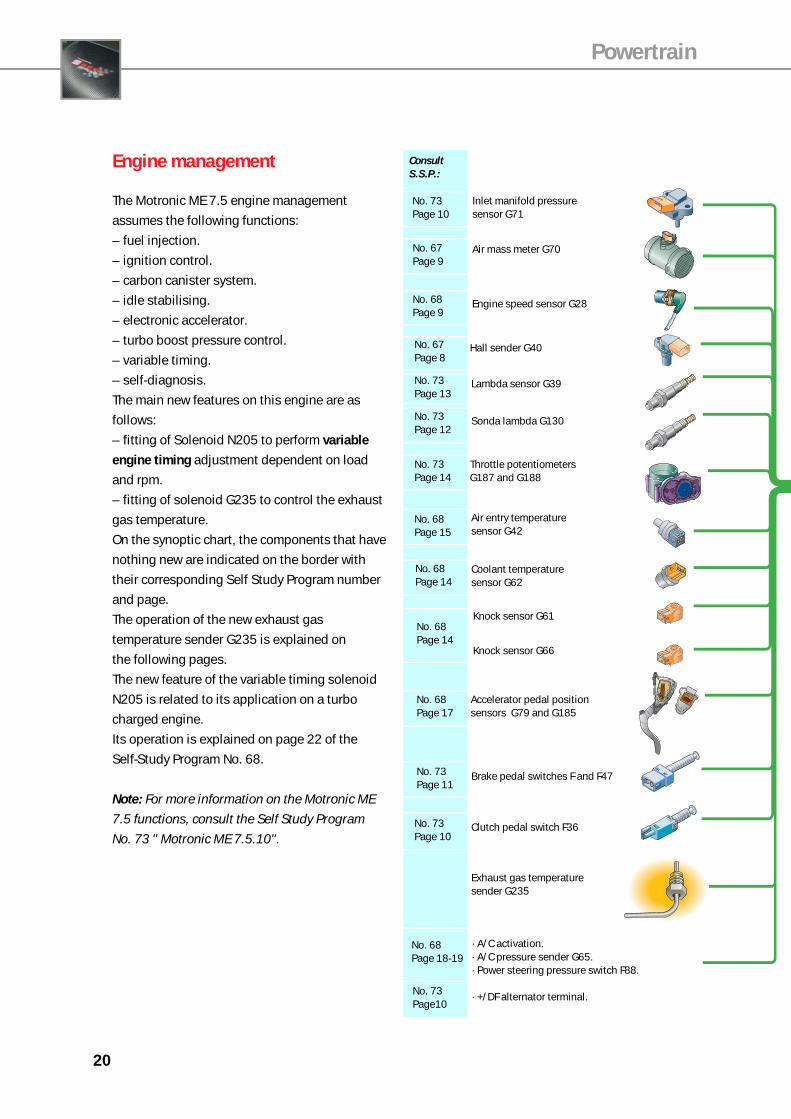
Engine management
The Motronic ME 7.5 engine management
assumes the following functions:
– fuel injection.
– ignition control.
– carbon canister system.
– idle stabilising.
– electronic accelerator.
– turbo boost pressure control.
– variable timing.
– self-diagnosis.
The main new features on this engine are as
follows:
– fitting of Solenoid N205 to perform variable
engine timing adjustment dependent on load
and rpm.
– fitting of solenoid G235 to control the exhaust
gas temperature.
On the synoptic chart, the components that have
nothing new are indicated on the border with
their corresponding Self Study Program number
and page.
The operation of the new exhaust gas
temperature sender G235 is explained on
the following pages.
The new feature of the variable timing solenoid
N205 is related to its application on a turbo
charged engine.
Its operation is explained on page 22 of the
Self-Study Program No. 68.
Note: For more information on the Motronic ME
7.5 functions, consult the Self Study Program
No. 73 " Motronic ME 7.5.10".
Powertrain
Consult S.S.P.:
Engine speed sensor G28
Air mass meter G70
Inlet manifold pressure sensor G71
Hall sender G40
Lambda sensor G39
Sonda lambda G130
Throttle potentiometers G187 and G188
Air entry temperature sensor G42
Coolant temperature sensor G62
Knock sensor G61
Knock sensor G66
Accelerator pedal position sensors G79 and G185
Brake pedal switches F and F47
Clutch pedal switch F36
Exhaust gas temperature sender G235
· A/C activation.· A/C pressure sender G65.· Power steering pressure switch F88.
· +/DF alternator terminal.
No. 67Page 9
No. 68Page 9
No. 73Page 12
No. 67Page 8
No. 68Page 15
No. 73Page 13
No. 73Page 14
No. 68Page 14
No. 68Page 14
No. 73Page 11
No. 68Page 17
No. 73Page 10
No. 68Page 18-19
No. 73Page10
No. 73Page 10
21
Powertrain
ABS
rpmx1000 km/h
AT04-23
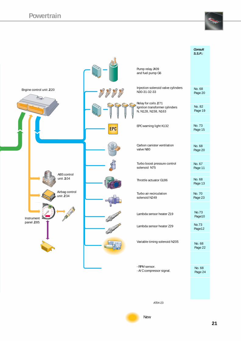
Pump relay J409 and fuel pump G6
Injection solenoid valve cylindersN30-31-32-33
Relay for coils J271Ignition transformer cylindersN, N128, N158, N163
Carbon canister ventilation valve N80
Turbo boost pressure control solenoid N75
Throttle actuator G186
Turbo air recirculation solenoid N249
Lambda sensor heater Z19
Lambda sensor heater Z29
EPC warning light K132
- RPM sensor.- A/C compressor signal.
Variable timing solenoid N205
No. 68Page 20
No. 68Page 20
No. 67Page 11
No. 68Page 13
No. 73Page 15
No. 70Page 23
No. 68Page 22
No. 68Page 24
Consult S.S.P.:
No. 82Page 19
No.73Page10
No.73Page12
ABS control unit J104
Airbag control unit J234
Instrument panel J285
Engine control unit J220
New

22
Powertrain
AT04-24
Electronic control unit
Tempeature sender
Thermally insulated conductor
Exhaust gas temperature sender G235
This is located in the turbo casing and it is composed of a temperature sender and an
electronic control unit.
This sensor picks up the temperature of the exhaust gas. The control unit uses this signal to
protect the exhaust manifold and the turbo.
The maximum allowable temperature for these components is 950 °C. When this value is
exceeded, the control unit intervenes and reduces the injection time until the temperature drops.
AT04-25
23
AT04-26
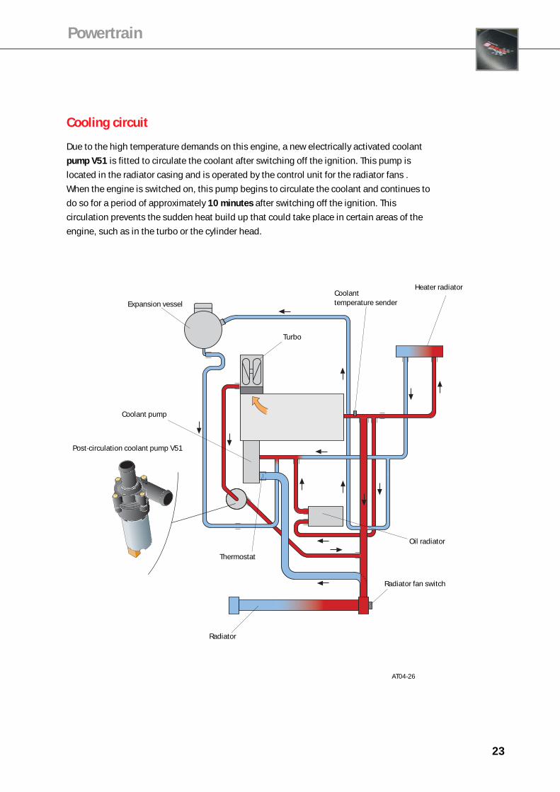
Cooling circuit
Due to the high temperature demands on this engine, a new electrically activated coolant
pump V51 is fitted to circulate the coolant after switching off the ignition. This pump is
located in the radiator casing and is operated by the control unit for the radiator fans .
When the engine is switched on, this pump begins to circulate the coolant and continues to
do so for a period of approximately 10 minutes after switching off the ignition. This
circulation prevents the sudden heat build up that could take place in certain areas of the
engine, such as in the turbo or the cylinder head.
Coolant temperature senderExpansion vessel
Turbo
Thermostat
Post-circulation coolant pump V51
Radiator
Radiator fan switch
Oil radiator
Heater radiator
Coolant pump
Powertrain

24
Input signal
Output signal
Positive supply
Earth
Bi directional signal
CAN-Bus signal
Colour codes
Powertrain

25
G39
Functional wiring diagram
D/50 Ignition switch.F36 Clutch pedal switch.F/F47 Brake pedal switch.F88 Power steering pressure switch.G6 Fuel pump.G28 Engine speed sensor.G39 Pre catalyst lambda sensor .G40 Hall sender.G42 Air entry temperature sensor.G61 Knock sensor 1.G62 Coolant temperature sensor.G66 Knock sensor 2.G70 Air mass meter.G71 Inlet manifold pressure sensor.G79 Accelerator pedal position sensor.G130 Post catalyst lambda sensor.G185 Accelerator pedal position sensor.G186 Throttle actuator.G187 Throttle potentiometer 1.G188 Throttle potentiometer 2.G235 Exhaust gas temperature sender.J220 Engine control unit.J234 Airbag control unit.J271 Ignition coil supply relay.J285 Instrument panel control unit.J409 Fuel pump relay.M9/10 Brake light bulbs.N Ignition transformer 1.N30 Injection solenoid valve cylinder 1.N31 Injection solenoid valve cylinder 2.N32 Injection solenoid valve cylinder 3.N33 Injection solenoid valve cylinder 4.N75 Turbo boost pressure control solenoid.N80 Carbon canister ventilation valve.N128 Ignition transformer cylinder 2.N158 Ignition transformer cylinder 3.N163 Ignition transformer cylinder 4.N205 Variable timing solenoid.N249 Turbo air recirculation solenoid.E45 Cruise control.Z19 Front lambda sensor heater.Z29 Rear lambda sensor heater.
Terminal 58 & 60 CAN-Bus line.Terminal 40 A/C activation signal.Terminal 41 A/C compressor signal.
Powertrain
AT04-27
26
Powertrain
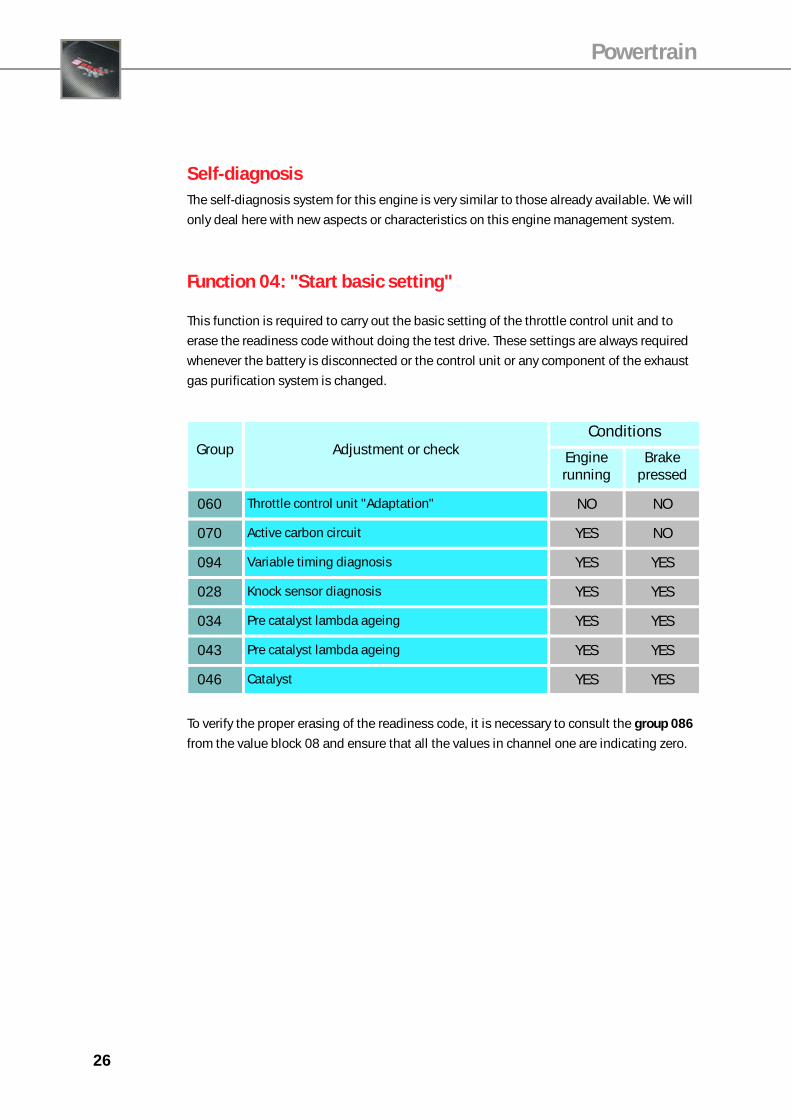
Self-diagnosisThe self-diagnosis system for this engine is very similar to those already available. We will
only deal here with new aspects or characteristics on this engine management system.
Group Adjustment or checkConditions
Engine running
Brake pressed
060 Throttle control unit "Adaptation" NO NO
070 Active carbon circuit YES NO
094 Variable timing diagnosis YES YES
028 Knock sensor diagnosis YES YES
034 Pre catalyst lambda ageing YES YES
043 Pre catalyst lambda ageing YES YES
046 Catalyst YES YES
Function 04: "Start basic setting"
This function is required to carry out the basic setting of the throttle control unit and to
erase the readiness code without doing the test drive. These settings are always required
whenever the battery is disconnected or the control unit or any component of the exhaust
gas purification system is changed.
To verify the proper erasing of the readiness code, it is necessary to consult the group 086
from the value block 08 and ensure that all the values in channel one are indicating zero.

ING04at