Embed Size (px)
Citation preview
Leon-Garcia & Widjaja: Communication NetworksCopyright ©2000 The McGraw Hill Companies
A Little More on Chapter 7And Start Chapter 8 TCP/IP
Leon-Garcia & Widjaja: Communication NetworksCopyright ©2000 The McGraw Hill Companies
Today
• C7: Count-to-Infinity Problem in Distance Vector Routing
• C7: Traffic management and Quality of Service
• C7:Congestion Control via Leaky Buckets and TCP Sliding Windows
• C8: Introduction to TCP/IP
Leon-Garcia & Widjaja: Communication NetworksCopyright ©2000 The McGraw Hill Companies
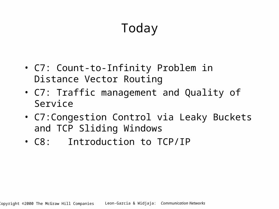
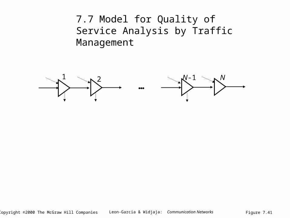
1 2 NN-1
Figure 7.41
…
7.7 Model for Quality of Service Analysis by Traffic Management
Leon-Garcia & Widjaja: Communication NetworksCopyright ©2000 The McGraw Hill Companies
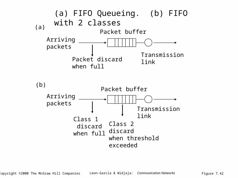
Packet buffer
Transmission link
Arrivingpackets
Packet discardwhen full
Packet buffer
Transmissionlink
Arrivingpackets
Class 1 discardwhen full
Class 2discardwhen thresholdexceeded
(a)
(b)
Figure 7.42
(a) FIFO Queueing. (b) FIFO with 2 classes
Leon-Garcia & Widjaja: Communication NetworksCopyright ©2000 The McGraw Hill Companies
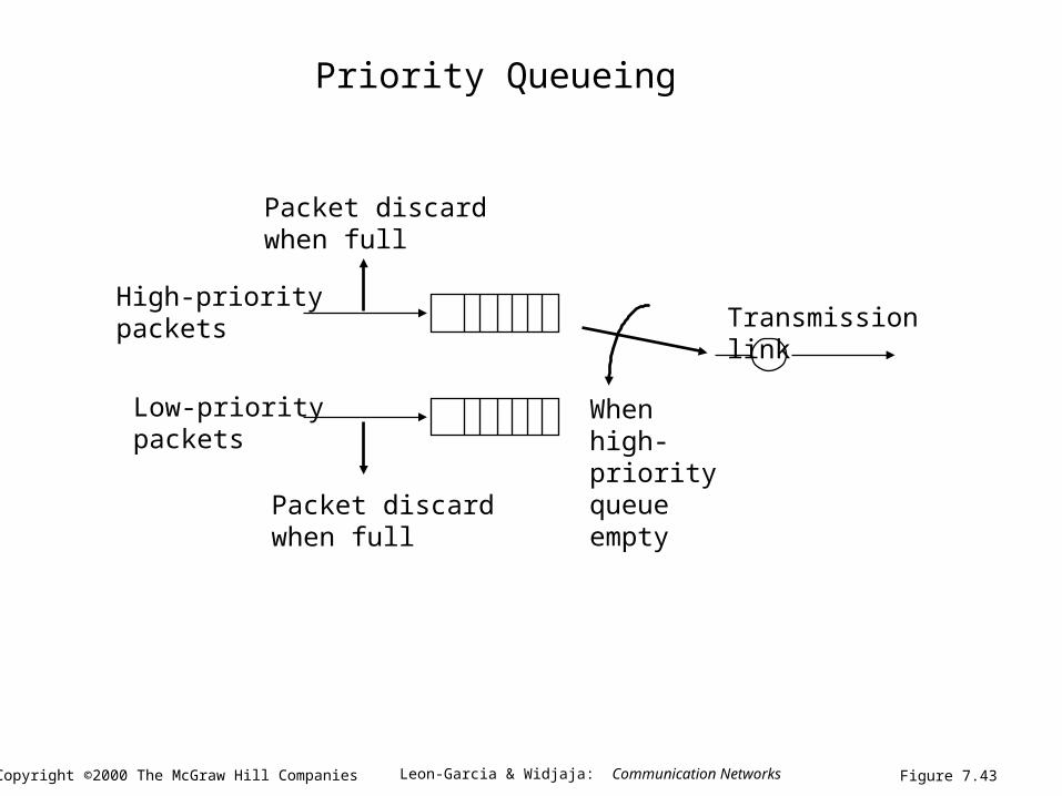
Transmission link
Packet discardwhen full
High-prioritypackets
Low-prioritypackets
Packet discardwhen full
When high-priorityqueue empty
Figure 7.43
Priority Queueing
Leon-Garcia & Widjaja: Communication NetworksCopyright ©2000 The McGraw Hill Companies
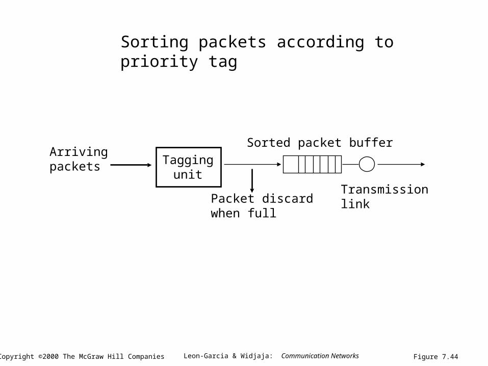
Sorted packet buffer
Transmissionlink
Arrivingpackets
Packet discardwhen full
Taggingunit
Figure 7.44
Sorting packets according to priority tag
Leon-Garcia & Widjaja: Communication NetworksCopyright ©2000 The McGraw Hill Companies
48
63
2
1
5 7
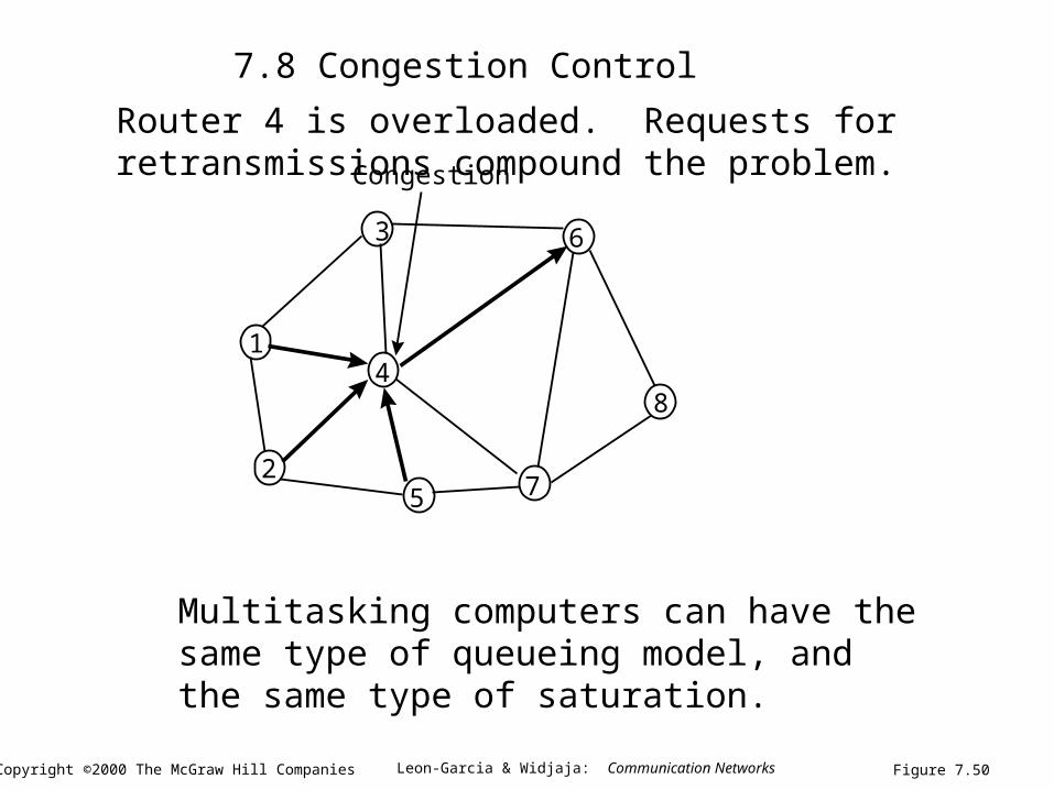
Congestion
Figure 7.50
Router 4 is overloaded. Requests for retransmissions compound the problem.
Multitasking computers can have the same type of queueing model, and the same type of saturation.
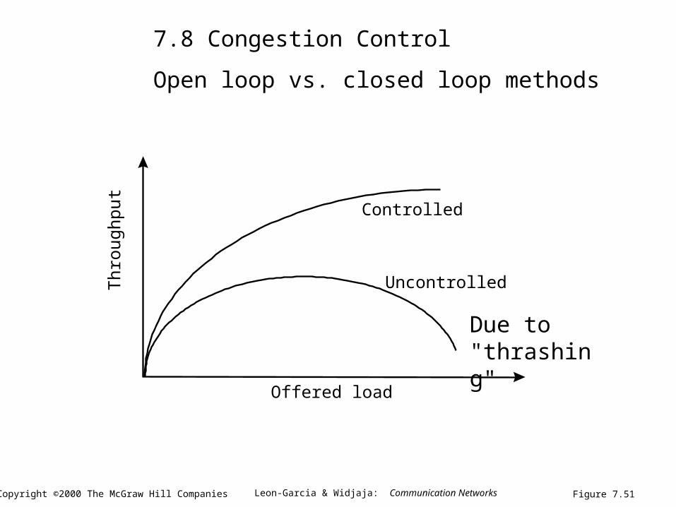
7.8 Congestion Control
Leon-Garcia & Widjaja: Communication NetworksCopyright ©2000 The McGraw Hill Companies
Offered load
Thr
ough
put
Controlled
Uncontrolled
Figure 7.51
7.8 Congestion Control
Open loop vs. closed loop methods
Due to "thrashing"
Leon-Garcia & Widjaja: Communication NetworksCopyright ©2000 The McGraw Hill Companies
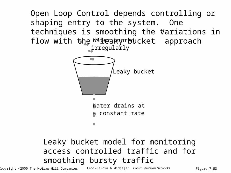
Water drains ata constant rate
Leaky bucket
Water pouredirregularly
Figure 7.53
Open Loop Control depends controlling or shaping entry to the system. One techniques is smoothing the variations in flow with the “leaky bucket” approach
Leaky bucket model for monitoring access controlled traffic and for smoothing bursty traffic
Leon-Garcia & Widjaja: Communication NetworksCopyright ©2000 The McGraw Hill Companies
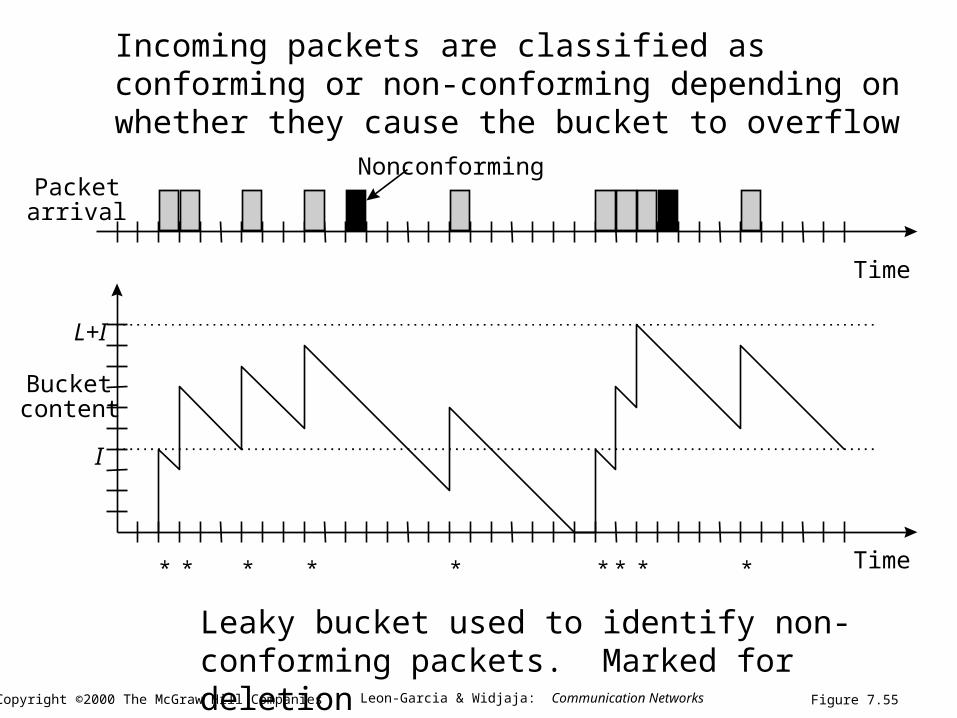
I
L+I
Bucketcontent
Time
Time
Packetarrival
Nonconforming
* * * * * * * **
Figure 7.55
Incoming packets are classified as conforming or non-conforming depending on whether they cause the bucket to overflow
Leaky bucket used to identify non-conforming packets. Marked for deletion
Leon-Garcia & Widjaja: Communication NetworksCopyright ©2000 The McGraw Hill Companies
Time0 1 2 3
Time0 1 2 3
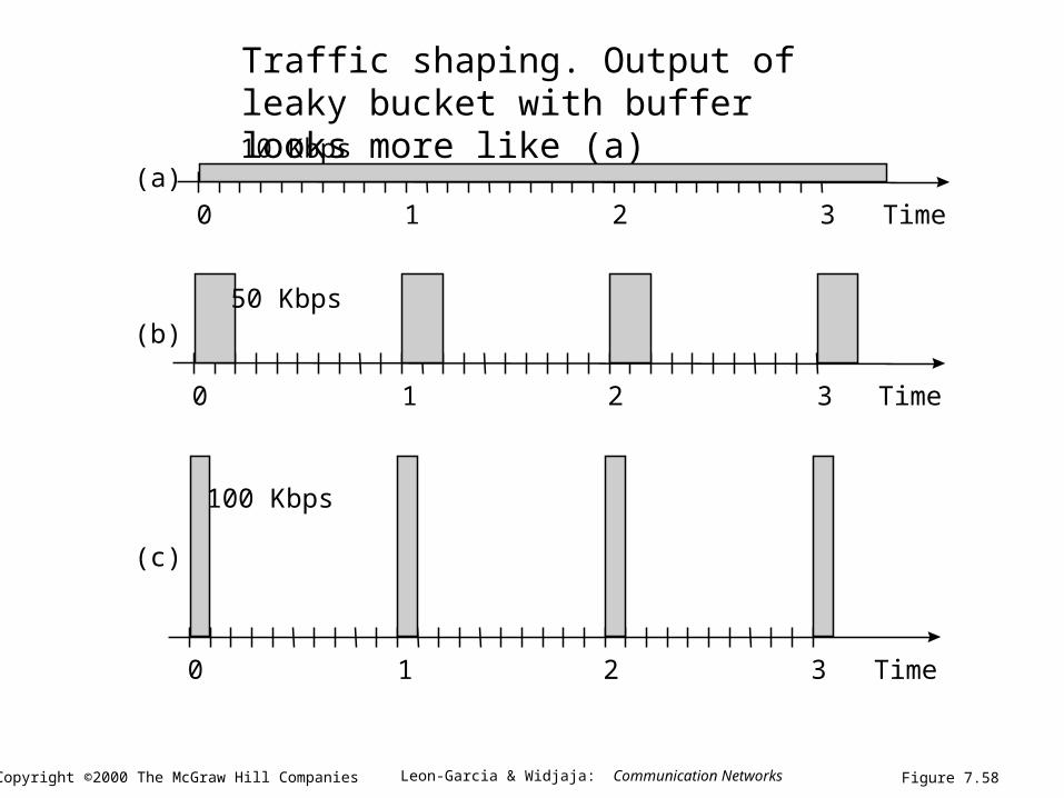
10 Kbps
Time0 1 2 3
50 Kbps
100 Kbps
(a)
(b)
(c)
Figure 7.58
Traffic shaping. Output of leaky bucket with buffer looks more like (a)
Leon-Garcia & Widjaja: Communication NetworksCopyright ©2000 The McGraw Hill Companies
TCP uses Closed Loop Congestion Control
• TCP provides end-to-end flow control to avoid overunning a slow receiver by a sliding window. Each byte is given a sequence number! The sender cannot send a new byte unless it is in the allowable “advertised window”
• However this advertised window does not prevent intermediate routers from overflowing due to congestion
• To try to optimize speed of transmission TCP establishes a second window called the “congestion window”
• At any time the window used is the smaller of the two.
Leon-Garcia & Widjaja: Communication NetworksCopyright ©2000 The McGraw Hill Companies
How Does the Congestion Window Work?
• The size of the congestion window is automatically adjusted depending the experience of the receiver:
• It starts with a small value: one maximum length “segment,” which is the PDU at the transport level
• It then ramps up exponentially, doubling on each transmission until it reaches a congestion threshold-- initially "65K bytes." Graph shows 16 x 65K.
• It then goes up linearly until a time out is experienced --assumed to be due to congestion
• The size of the congestion window is then cut back to its initial value and the congestion threshold is cut to half its initial value
Leon-Garcia & Widjaja: Communication NetworksCopyright ©2000 The McGraw Hill Companies
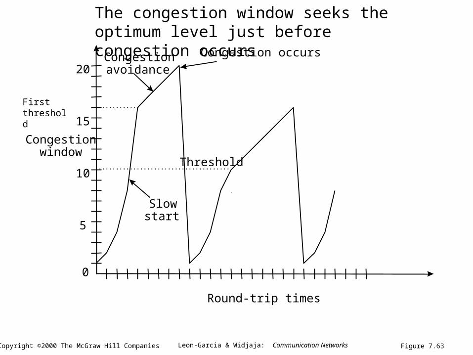
Congestionwindow
10
5
15
20
0
Round-trip times
Slowstart
Congestionavoidance
Congestion occurs
Threshold
Figure 7.63
The congestion window seeks the optimum level just before congestion occurs
First threshold
Leon-Garcia & Widjaja: Communication NetworksCopyright ©2000 The McGraw Hill Companies
Material in Chapter 8
• 1. TCP/IP Architecture
• 2. Internet Protocol IP Version 4
• 3. IP Version 6 (skip)
• 4. Transport Layer Protocols (TCP and UDP)
• 5. DHCP and Mobile Internet (just a little)
• 6 Internet Routing
• 7. Multicast Routing (skip)
Leon-Garcia & Widjaja: Communication NetworksCopyright ©2000 The McGraw Hill Companies
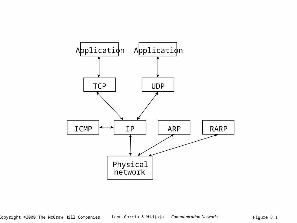
Application
TCP UDP
IPICMP ARP RARP
Physicalnetwork
Application
Figure 8.1
Leon-Garcia & Widjaja: Communication NetworksCopyright ©2000 The McGraw Hill Companies
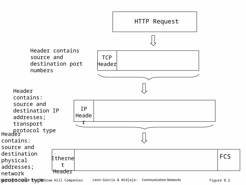
HTTP Request
TCP Header
Header contains source and destination port numbers
Header contains: source and destination IP addresses; transport protocol type
IP Header
Header contains: source and destination physical addresses; network protocol type
FCSEthernet Header
Figure 8.2
Leon-Garcia & Widjaja: Communication NetworksCopyright ©2000 The McGraw Hill Companies
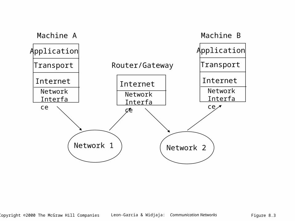
Application
Transport
InternetNetwork Interface
Application
Transport
InternetInternet
Network 1 Network 2
Machine A Machine B
Router/Gateway
Network Interface
Network Interface
Figure 8.3
Leon-Garcia & Widjaja: Communication NetworksCopyright ©2000 The McGraw Hill Companies
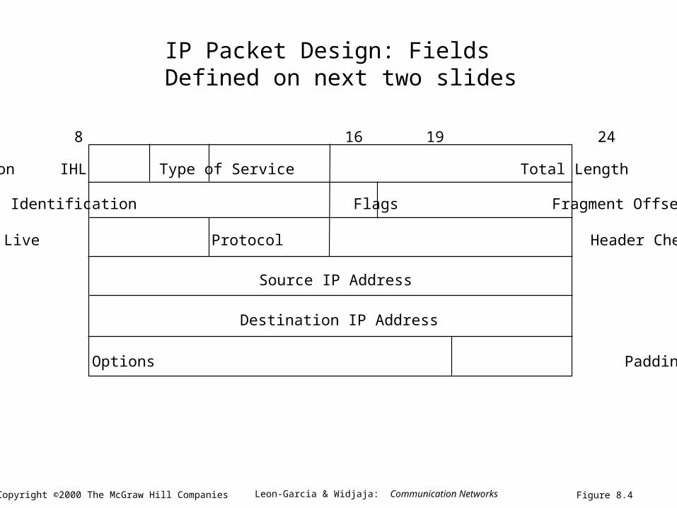
Version IHL Type of Service Total Length
Identification Flags Fragment Offset
Time to Live Protocol Header Checksum
Source IP Address
Destination IP Address
Options Padding
0 4 8 16 19 24 31
Figure 8.4
IP Packet Design: Fields Defined on next two slides
Leon-Garcia & Widjaja: Communication NetworksCopyright ©2000 The McGraw Hill Companies
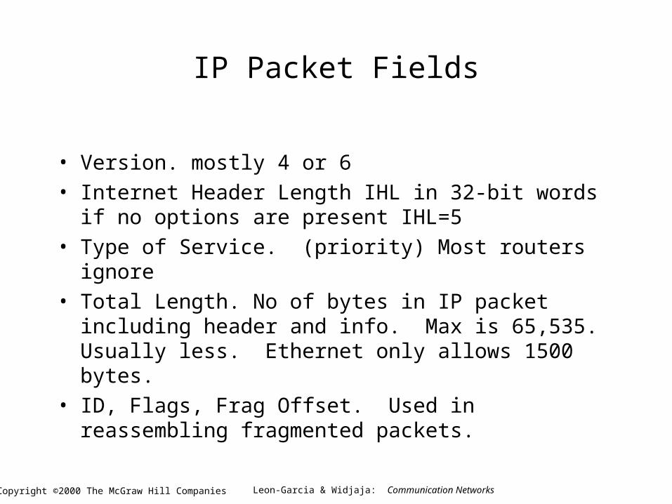
IP Packet Fields
• Version. mostly 4 or 6
• Internet Header Length IHL in 32-bit words if no options are present IHL=5
• Type of Service. (priority) Most routers ignore
• Total Length. No of bytes in IP packet including header and info. Max is 65,535. Usually less. Ethernet only allows 1500 bytes.
• ID, Flags, Frag Offset. Used in reassembling fragmented packets.
Leon-Garcia & Widjaja: Communication NetworksCopyright ©2000 The McGraw Hill Companies
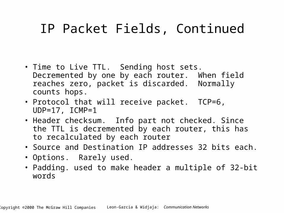
IP Packet Fields, Continued
• Time to Live TTL. Sending host sets. Decremented by one by each router. When field reaches zero, packet is discarded. Normally counts hops.
• Protocol that will receive packet. TCP=6, UDP=17, ICMP=1
• Header checksum. Info part not checked. Since the TTL is decremented by each router, this has to recalculated by each router
• Source and Destination IP addresses 32 bits each.• Options. Rarely used.• Padding. used to make header a multiple of 32-bit words
Leon-Garcia & Widjaja: Communication NetworksCopyright ©2000 The McGraw Hill Companies
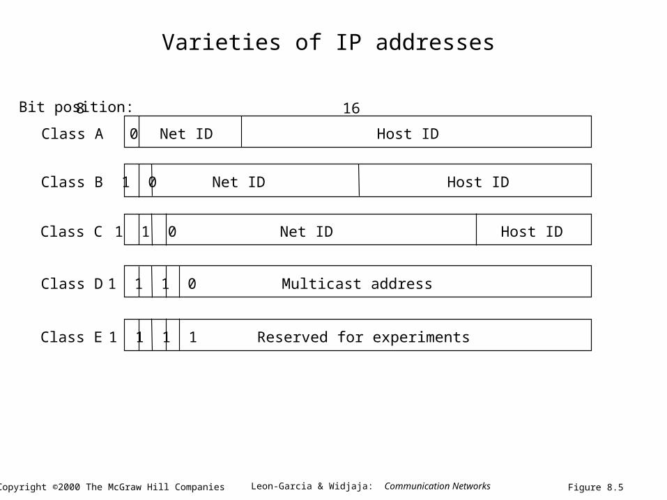
0 Net ID Host ID
Net ID Host ID1 0
Net ID Host ID1 1 0
1 1 1 0 Multicast address
1 1 1 1 Reserved for experiments
Class A
Class B
Class C
Class D
Class E
0 1 2 3 8 16 31Bit position:
Figure 8.5
Varieties of IP addresses
Leon-Garcia & Widjaja: Communication NetworksCopyright ©2000 The McGraw Hill Companies
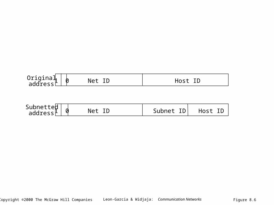
Originaladdress
Subnettedaddress
Net ID Host ID1 0
Net ID Host ID1 0 Subnet ID
Figure 8.6
Leon-Garcia & Widjaja: Communication NetworksCopyright ©2000 The McGraw Hill Companies
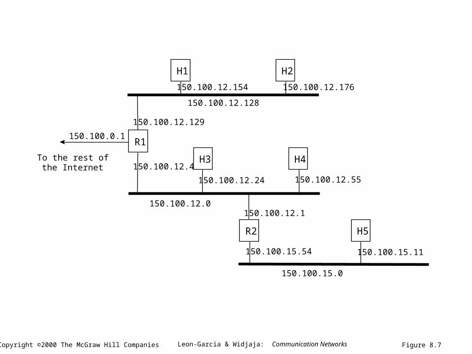
R1
H1 H2
H3 H4
R2 H5
To the rest ofthe Internet
150.100.0.1
150.100.12.128
150.100.12.0
150.100.12.176150.100.12.154
150.100.12.24 150.100.12.55
150.100.12.1
150.100.15.54
150.100.15.0
150.100.15.11
150.100.12.129
150.100.12.4
Figure 8.7