Embed Size (px)
Citation preview
1
LEOP Preparation and Realization of the first two Galileo Satellites by CNESOC Flight Dynamics
Sylvain Delattre 1 Centre National d’Etudes Spatiales (CNES), 31401 Toulouse Cedex 09, France
and Laurence Lorda 2, François Desclaux 3, Angélique Gaudel-Vacaresse 4, Denis Carbonne 5, Pierre Labourdette 6
Centre National d’Etudes Spatiales (CNES), 31401 Toulouse Cedex 09, France
Frank Dreger 7, Isidro Munoz 8 ESA/ESOC, Robert-Bosch-Str. 5 - 64293 Darmstadt - Germany
Daniel Navarro-Reyes 9 ESA/ESTEC, Keplerlaan 1 Noordwijk - The Netherlands
This paper presents the preparation, rehearsal and realization of the LEOP (Launch and Early Orbital Phase) of the first two satellites of the Galileo constellation by the CNES Flight Dynamics Centre in Toulouse, France. Those operations were the starting point of the future European Navigation System and they were also the result of a close collaboration between the CNES and ESOC flight dynamics teams for preparation and operations in interface with ESA and DLR. Moreover, the originality of this mission was that the first six days were under the responsibility of CNES for the commanding and the flight dynamics and that the second part of the LEOP was in shared responsibility between the routine centre at DLR for the commanding and the CNES FDS for flight dynamics. This paper will focus on the flight dynamics side of the mission, describing shortly the mission analysis and entering into the details of the operational concepts applied at CNES to support this LEOP : hardware and software architecture, team organization, shifts patterns, interfaces with other entities, procedures and actual operations description. The purpose is not to address any confidential aspects of the LEOP but to describe the main operational concepts that came out of this European cooperation.
I. Introduction S indicated in the abstract above, the topics addressed in the following paper will focus more on the operational aspects than on the flight dynamics ones. This idea is really to give an overview of how the operations were
prepared and realized by CNES and ESOC FDS (named CNESOC FDS in the document). Moreover, the purpose of the present paper is not to enter deeply into details on the Galileo constellation, next chapter only gives a quick summary of the context of the mission.
1 Flight Dynamics Engineer, CNES - DCT/SB/MS, [email protected]. 2 Flight Dynamics Engineer, CNES - DCT/SB/MS, [email protected] 3 Flight Dynamics Engineer, CNES - DCT/SB/MS, [email protected] 4 Flight Dynamics Engineer, CNES - DCT/SB/MO, [email protected] 5 Flight Dynamics Engineer, CNES - DCT/SB/MO, [email protected] 6 Flight Dynamics Engineer, CNES - DCT/SB/MO, [email protected] 7 ESOC Flight dynamics, [email protected] 8 ESOC Flight dynamics, [email protected] 9 ESA GPO, [email protected]
A
2
II. The IOV1 mission for Galileo
A. Overall description The well-known Galileo constellation will be the European global navigation satellite system, providing a highly
accurate, guaranteed global positioning service under civilian control. It will be inter-operable with the two other global satellite navigation systems: the American GPS (Global Positioning System) and the Russian GLONASS (GLObal NAvigation Satellite System).
The Galileo constellation is a Walker 27-3-1 constellation with three spare satellites, one per plane. This leads to a total of 30 satellites in 3 planes. Planes are separated by 120 deg and satellites in each plane are separated by 40 deg, with a phasing factor of 13.33 deg (phasing factor being the angle between two satellites in two consecutive planes). Main characteristics of the orbits are: inclination i of 56 deg and mean semi-major axis a of 29600 km. The constellation will be populated by successive launches, mainly dual with Soyuz from Kourou.
The IOV mission (In Orbit Validation) covers the launch of the first four operational satellites in 2011 for IOV1 and 2012 for IOV2. The targeted orbits are such that the in-flight configuration of those four satellites will make it possible to validate both space segment and infrastructures.
The IOV1 launch (with the satellites PFM and FM2) occurred on October the 21st 2012 with the first Soyuz launch from Kourou and the LEOP operations ended on November 30th 2012 (“end” meaning up to the fine positioning, see below for details).
B. IOV1 flight dynamics mission constraints For this mission, high level constraints are coming from the Galileo Project Office (GPO) from ESA and have
direct consequences on the LEOP design at CNESOC FDS. They are detailed hereafter: 1. The routine constraints The Galileo mission has been designed at a system level to minimize the routine operations maneuvers on the
satellites. This criterion was the driving concept for the dimensioning as it is expected to perform only one maneuver over 12 years for each satellite.
The constellation geometry is modified due to the effect of the lunisolar potential (effect on i, RAAN and AoL), the solar pressure radiation (preponderant effect on AoL) and the non homogeneity of the Earth potential (preponderant effect on AoL). The overall constellation geometry tolerances during its lifetime are the following:
• Across track orbit keeping (influence of the Third Body perturbations): RAAN variations < +/- 2deg, i variations < +/- 2deg
• Along track orbit keeping (major influence of the Earth Potential and Solar Pressure): relative along track in the same orbital plane <+/- 1.5deg, relative phasing variation between two adjacent planes <+/- 1.5deg
Analyses were performed by both Space Segment and ESA to identify the impacts of these constraints on the initial conditions at the beginning of the routine operations (i.e. end of the LEOP phase). The conclusions are the following:
• The station keeping will be made in absolute with respect to a reference constellation. • Inclination i and RAAN are guaranteed by the injection, corrected during LEOP if necessary. No need for
orbital corrections during routine. • Phasing in the plane adjusted by the initial a and AoL. No need for orbital corrections during routine. • Phasing between two adjacent planes maintaining will be the only reason for orbital corrections during
routine, limited to one maneuver per satellite. A consequence will be that the targeted orbit will be computed by ESA during operations (because it may
depend on the initial injection parameters or on the launch epoch) and this orbit will be the one to reach at the end of the LEOP. If CNESOC FDS can guarantee that this target is correctly achieved, system analysis ensures that the station keeping will be as expected. This orbit will be provided for each satellite of the constellation, then for the first two satellites of the IOV1 mission.
2. Impact on the LEOP operations of the routine constraints Above section introduced the notion of target orbit that LOCC will have to aim at. This is the major constraint on
the Galileo operation because this target orbit will have to be reached with very strict thresholds. Once again, this is to guarantee that the initial parameters discussed above are correct. The requirements on the accuracy are the following (values given at 3 sigma):
+/-5m on a, e < 0.0005 +/-0.01deg on I,
3
+/-0.01deg on RAAN, +/-0.002deg on AoL <=> +/-1000m along track on X. Main impacts are the followings:
• In operations, the FDS must be able to take into account a new target orbit provided by ESA. • The operational software and stations ground support must be accurate enough to reach the target. • The strategy has to fit with other system constraints such as total LEOP duration or fuel consumption
minimization. • The mission analysis has to check that those constraints are reachable in any cases of dispersions.
3. Other constraints In addition to the major flight dynamics constraints listed above, CNESOC FDS had to respect some other
constraints that impacted the operations design. Are listed below the major ones, i.e. really affecting the design of the mission:
• LEOP duration can not exceed 46 days, • The drift phase (meaning phase without maneuvers) is 22 days, • Drift start must not last more than 5.5 days.
III. The entities involved For the CNES FDS, the originality of this mission is first the flight dynamics challenge (presented above) of
reaching a very accurate orbit with classical operational means and second to realize this mission in a complex European project organization leading to various interfaces either during preparation of the operations and during operations themselves. The purpose of the following chapter is to describe this context and the CNESOC FDS position inside it.
A. The CNESOC entity The core of the LEOP organization is based on a common answer by the French Space Agency (CNES) in
Toulouse, France and the European Space Operations Center (ESOC) in Darmstadt, Germany. Inside the project, this entity became the CNESOC one. From high level point of view, there is one single entity, speaking and deciding as one. A complete description of this organization can be found in the paper referenced 1.
Then, given this organization, the CNESOC flight dynamics team organized the preparation and realization of the operations in a way described in chapter IV.
B. The GPO entity At the European Space Agency (ESA), the Galileo Project Office (GPO) leads the coordination between the
LEOP center and the routine center. Concretely, one person at GPO is assigned to cover the CNESOC Flight Dynamics activities.
C. The DLR-GCC entity The Deutsches Zentrum für Luft und Raumfahrt (DLR) is Germany's national research center for aeronautics and
space. It is responsible for the routine center for Galileo named Galileo Control Center (GCC) which premises are located on the DLR facilities. CNESOC has to interface with GCC for all commanding aspects of the platform after the Command and Control Hand-over (see below for details).
D. The SPO entity SpaceOpal (SPO) is a joint undertaking between the German firm Gesellschaft für Raumfahrtanwendungen
(GfR) and the Italian company Telespazio. GfR was set up by the German space agency (DLR) to offer Galileo services. SPO is the contractual CNESOC client for the LEOP activity.
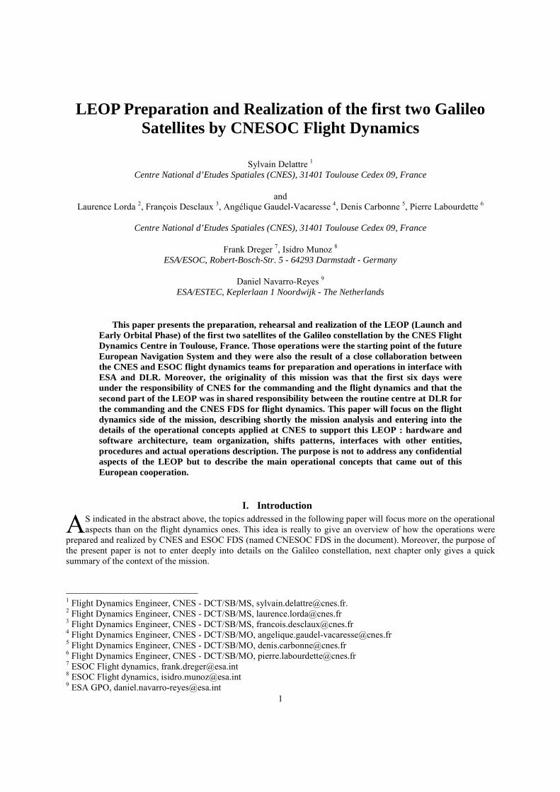
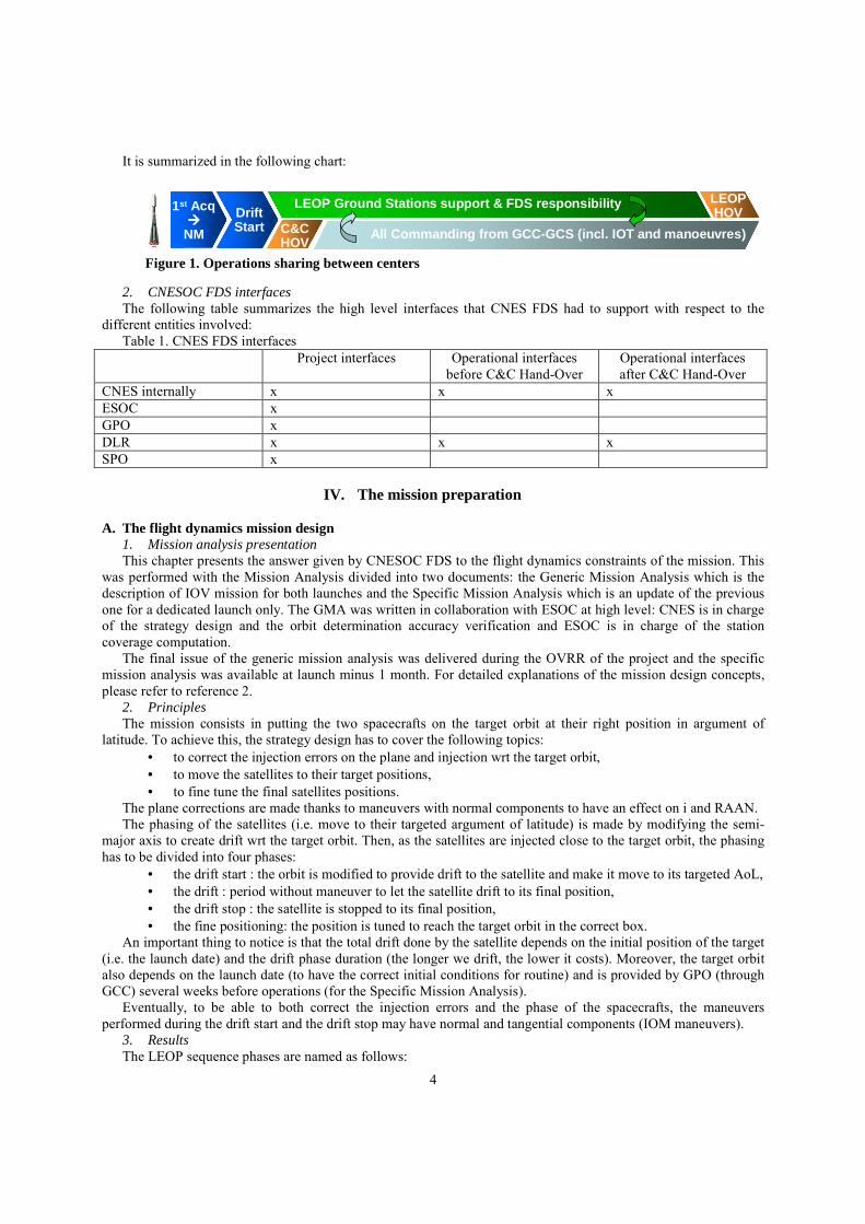
E. High level organization 1. Operations sharing between the CNESOC centers At CNESOC level, the operations are shared between the centers with one launch from CNES and the other one
from ESOC. At the IOV1 epoch, the sharing was: first launch from CNES, second one from ESOC. At project level, an agreement was found in December 2006 to involve both the LEOP and routine centers in the
operations. The main outcomes were: • Ground stations support and FDS responsibility is kept inside the LOCC up to the final hand-over, • The commanding is transferred from LOCC to GCC at DLR after the drift start.
4
It is summarized in the following chart:
2. CNESOC FDS interfaces The following table summarizes the high level interfaces that CNES FDS had to support with respect to the
different entities involved: Table 1. CNES FDS interfaces
Project interfaces Operational interfaces before C&C Hand-Over
Operational interfaces after C&C Hand-Over
CNES internally x x x ESOC x GPO x DLR x x x SPO x
IV. The mission preparation
A. The flight dynamics mission design 1. Mission analysis presentation This chapter presents the answer given by CNESOC FDS to the flight dynamics constraints of the mission. This
was performed with the Mission Analysis divided into two documents: the Generic Mission Analysis which is the description of IOV mission for both launches and the Specific Mission Analysis which is an update of the previous one for a dedicated launch only. The GMA was written in collaboration with ESOC at high level: CNES is in charge of the strategy design and the orbit determination accuracy verification and ESOC is in charge of the station coverage computation.
The final issue of the generic mission analysis was delivered during the OVRR of the project and the specific mission analysis was available at launch minus 1 month. For detailed explanations of the mission design concepts, please refer to reference 2.
2. Principles The mission consists in putting the two spacecrafts on the target orbit at their right position in argument of
latitude. To achieve this, the strategy design has to cover the following topics: • to correct the injection errors on the plane and injection wrt the target orbit, • to move the satellites to their target positions, • to fine tune the final satellites positions.
The plane corrections are made thanks to maneuvers with normal components to have an effect on i and RAAN. The phasing of the satellites (i.e. move to their targeted argument of latitude) is made by modifying the semi-
major axis to create drift wrt the target orbit. Then, as the satellites are injected close to the target orbit, the phasing has to be divided into four phases:
• the drift start : the orbit is modified to provide drift to the satellite and make it move to its targeted AoL, • the drift : period without maneuver to let the satellite drift to its final position, • the drift stop : the satellite is stopped to its final position, • the fine positioning: the position is tuned to reach the target orbit in the correct box.
An important thing to notice is that the total drift done by the satellite depends on the initial position of the target (i.e. the launch date) and the drift phase duration (the longer we drift, the lower it costs). Moreover, the target orbit also depends on the launch date (to have the correct initial conditions for routine) and is provided by GPO (through GCC) several weeks before operations (for the Specific Mission Analysis).
Eventually, to be able to both correct the injection errors and the phase of the spacecrafts, the maneuvers performed during the drift start and the drift stop may have normal and tangential components (IOM maneuvers).
3. Results The LEOP sequence phases are named as follows:
1st Acq����
NM
DriftStart All Commanding from GCC-GCS (incl. IOT and manoeuvres)
LEOP Ground Stations support & FDS responsibility LEOPHOV
C&CHOV
1st Acq����
NM
DriftStart All Commanding from GCC-GCS (incl. IOT and manoeuvres)
LEOP Ground Stations support & FDS responsibility LEOPHOV
C&CHOV
Figure 1. Operations sharing between centers
5
• A phase: drift start. 5.5 days duration, command and control from LOCC, • B phase: drift period. No maneuvers but IOT activities, command and control transferred to GCC, • C phase: drift stop maneuvers, • D phase: fine positioning.
To ensure that the target orbit was accurately reached, the mission analysis showed that given the dispersions and the mission constraints, between 6 and 14 maneuvers were expected on each satellite: 3 maneuvers during phase A, no maneuver during the phase B, 3 maneuvers during the phase C and up to 8 maneuvers during the phase D, the last maneuvers becoming smaller and smaller to guarantee the target achievement in any cases of dispersions.
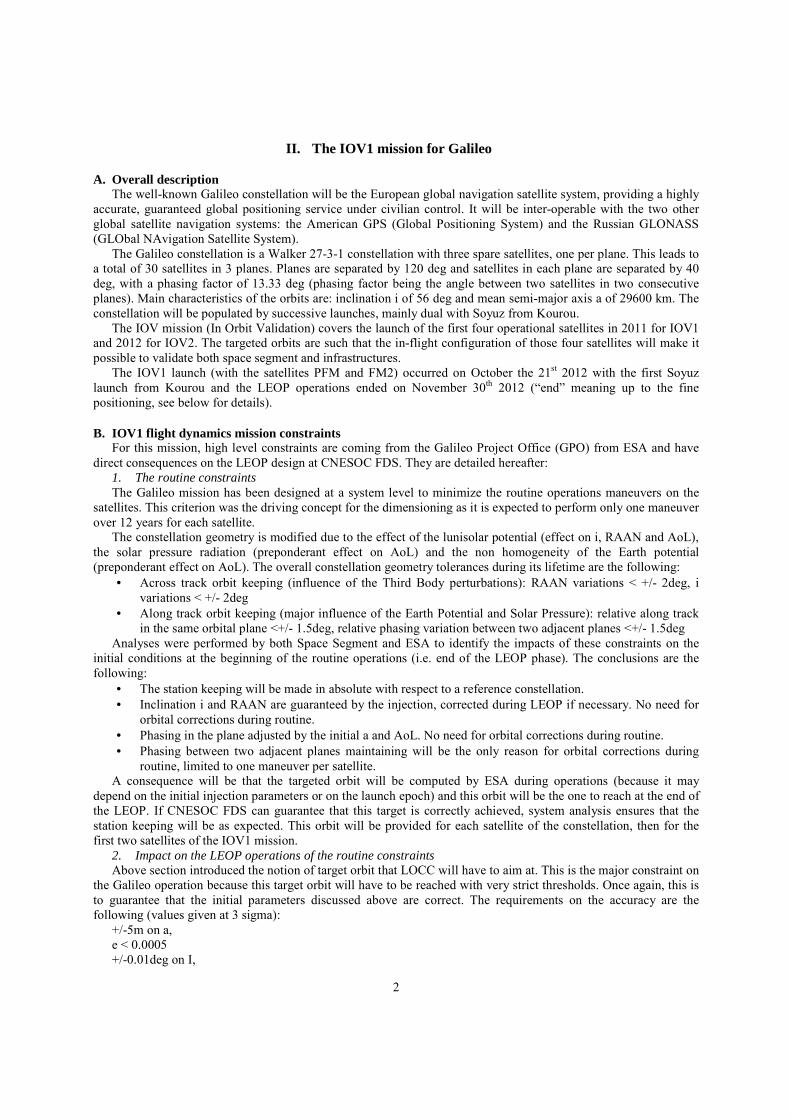
To have a more convenient organization of the operations, the driving constraint for the strategy design was to choose slots of maneuvers for each satellite that could be kept in any cases of dispersions. The slots of maneuvers were chosen taken into account the system level constraints, the satellite operational constraints, the ranging periods between maneuvers and the final ranging sessions to determine the final orbit. The resulting strategy respected this : the slots of the maneuvers are fixed, they last 4 hours (voluntary larger than necessary for dispersion robustness) and are valid in any cases of dispersions. During operations, the refining of the maneuver date and duration will be performed inside those slots.
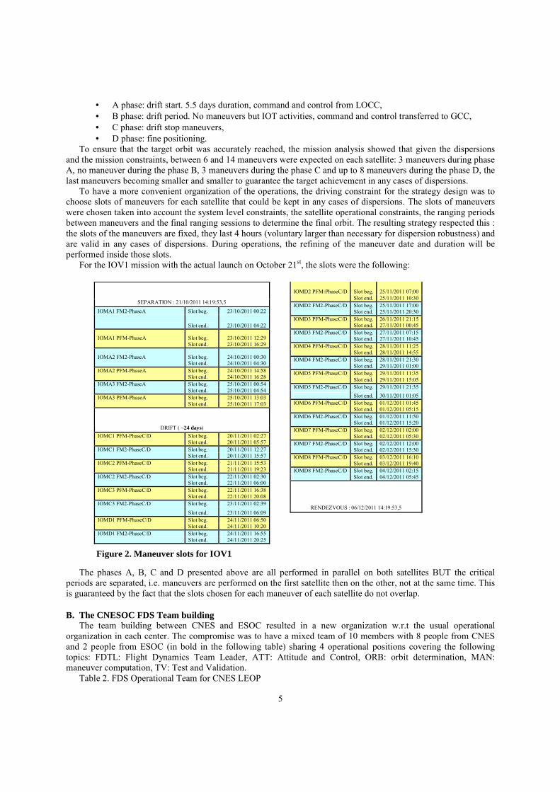
For the IOV1 mission with the actual launch on October 21st, the slots were the following:
The phases A, B, C and D presented above are all performed in parallel on both satellites BUT the critical
periods are separated, i.e. maneuvers are performed on the first satellite then on the other, not at the same time. This is guaranteed by the fact that the slots chosen for each maneuver of each satellite do not overlap.
B. The CNESOC FDS Team building The team building between CNES and ESOC resulted in a new organization w.r.t the usual operational
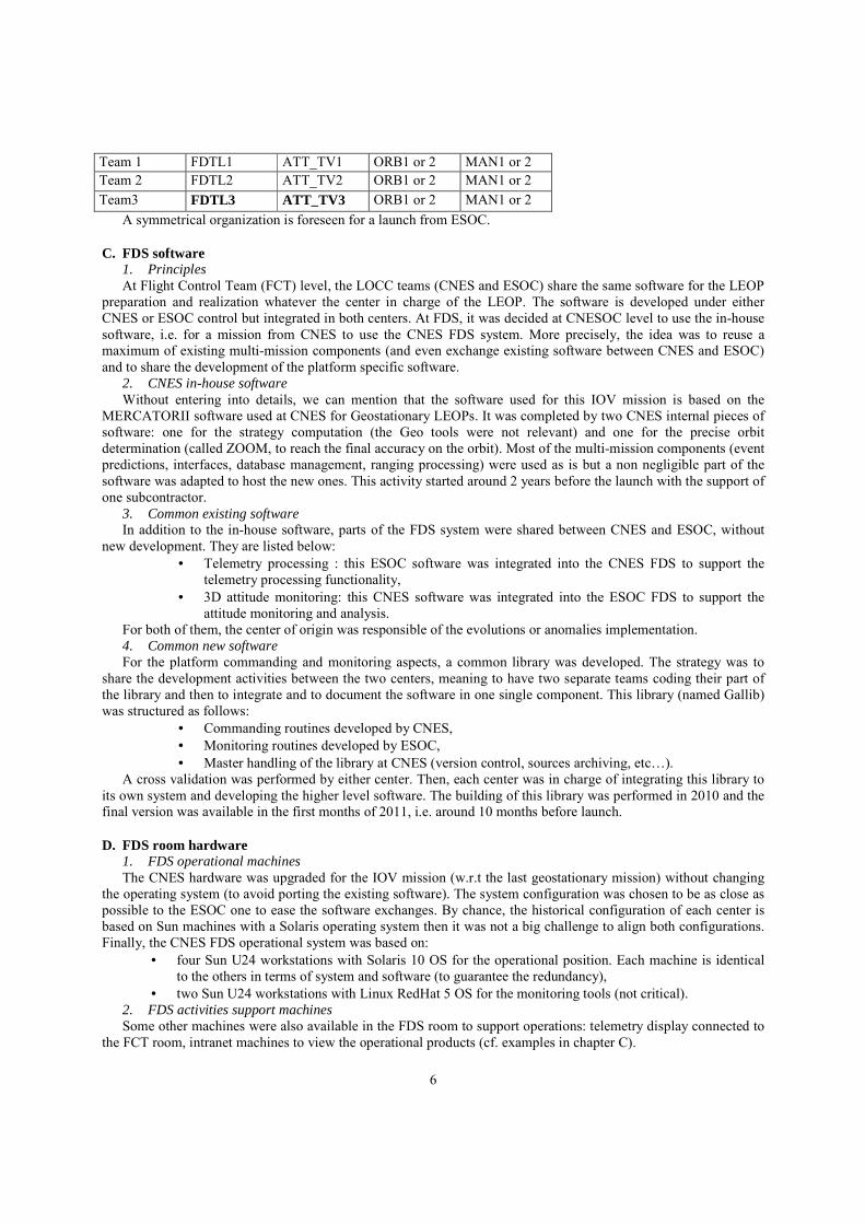
organization in each center. The compromise was to have a mixed team of 10 members with 8 people from CNES and 2 people from ESOC (in bold in the following table) sharing 4 operational positions covering the following topics: FDTL: Flight Dynamics Team Leader, ATT: Attitude and Control, ORB: orbit determination, MAN: maneuver computation, TV: Test and Validation.
Table 2. FDS Operational Team for CNES LEOP
SEPARATION : 21/10/2011 14:19:53,5
IOMA1 FM2-PhaseA Slot beg. 23/10/2011 00:22
Slot end. 23/10/2011 04:22
IOMA1 PFM-PhaseA Slot beg. 23/10/2011 12:29 Slot end. 23/10/2011 16:29
IOMA2 FM2-PhaseA Slot beg. 24/10/2011 00:30 Slot end. 24/10/2011 04:30 IOMA2 PFM-PhaseA Slot beg. 24/10/2011 14:58 Slot end. 24/10/2011 16:28 IOMA3 FM2-PhaseA Slot beg. 25/10/2011 00:54 Slot end. 25/10/2011 04:54 IOMA3 PFM-PhaseA Slot beg. 25/10/2011 13:03 Slot end. 25/10/2011 17:03
DRIFT ( ~24 days) IOMC1 PFM-PhaseC/D Slot beg. 20/11/2011 02:27 Slot end. 20/11/2011 05:57 IOMC1 FM2-PhaseC/D Slot beg. 20/11/2011 12:27 Slot end. 20/11/2011 15:57 IOMC2 PFM-PhaseC/D Slot beg. 21/11/2011 15:53 Slot end. 21/11/2011 19:23 IOMC2 FM2-PhaseC/D Slot beg. 22/11/2011 02:30 Slot end. 22/11/2011 06:00 IOMC3 PFM-PhaseC/D Slot beg. 22/11/2011 16:38 Slot end. 22/11/2011 20:08 IOMC3 FM2-PhaseC/D Slot beg. 23/11/2011 02:39
Slot end. 23/11/2011 06:09 IOMD1 PFM-PhaseC/D Slot beg. 24/11/2011 06:50 Slot end. 24/11/2011 10:20 IOMD1 FM2-PhaseC/D Slot beg. 24/11/2011 16:55 Slot end. 24/11/2011 20:25
IOMD2 PFM-PhaseC/D Slot beg. 25/11/2011 07:00 Slot end. 25/11/2011 10:30 IOMD2 FM2-PhaseC/D Slot beg. 25/11/2011 17:00 Slot end. 25/11/2011 20:30 IOMD3 PFM-PhaseC/D Slot beg. 26/11/2011 21:15 Slot end. 27/11/2011 00:45 IOMD3 FM2-PhaseC/D Slot beg. 27/11/2011 07:15 Slot end. 27/11/2011 10:45 IOMD4 PFM-PhaseC/D Slot beg. 28/11/2011 11:25 Slot end. 28/11/2011 14:55 IOMD4 FM2-PhaseC/D Slot beg. 28/11/2011 21:30 Slot end. 29/11/2011 01:00 IOMD5 PFM-PhaseC/D Slot beg. 29/11/2011 11:35 Slot end. 29/11/2011 15:05 IOMD5 FM2-PhaseC/D Slot beg. 29/11/2011 21:35 Slot end. 30/11/2011 01:05 IOMD6 PFM-PhaseC/D Slot beg. 01/12/2011 01:45 Slot end. 01/12/2011 05:15 IOMD6 FM2-PhaseC/D Slot beg. 01/12/2011 11:50 Slot end. 01/12/2011 15:20 IOMD7 PFM-PhaseC/D Slot beg. 02/12/2011 02:00 Slot end. 02/12/2011 05:30 IOMD7 FM2-PhaseC/D Slot beg. 02/12/2011 12:00 Slot end. 02/12/2011 15:30 IOMD8 PFM-PhaseC/D Slot beg. 03/12/2011 16:10 Slot end. 03/12/2011 19:40 IOMD8 FM2-PhaseC/D Slot beg. 04/12/2011 02:15 Slot end. 04/12/2011 05:45
RENDEZVOUS : 06/12/2011 14:19:53,5
Figure 2. Maneuver slots for IOV1
6
Team 1 FDTL1 ATT_TV1 ORB1 or 2 MAN1 or 2 Team 2 FDTL2 ATT_TV2 ORB1 or 2 MAN1 or 2 Team3 FDTL3 ATT_TV3 ORB1 or 2 MAN1 or 2
A symmetrical organization is foreseen for a launch from ESOC.
C. FDS software 1. Principles At Flight Control Team (FCT) level, the LOCC teams (CNES and ESOC) share the same software for the LEOP
preparation and realization whatever the center in charge of the LEOP. The software is developed under either CNES or ESOC control but integrated in both centers. At FDS, it was decided at CNESOC level to use the in-house software, i.e. for a mission from CNES to use the CNES FDS system. More precisely, the idea was to reuse a maximum of existing multi-mission components (and even exchange existing software between CNES and ESOC) and to share the development of the platform specific software.
2. CNES in-house software Without entering into details, we can mention that the software used for this IOV mission is based on the
MERCATORII software used at CNES for Geostationary LEOPs. It was completed by two CNES internal pieces of software: one for the strategy computation (the Geo tools were not relevant) and one for the precise orbit determination (called ZOOM, to reach the final accuracy on the orbit). Most of the multi-mission components (event predictions, interfaces, database management, ranging processing) were used as is but a non negligible part of the software was adapted to host the new ones. This activity started around 2 years before the launch with the support of one subcontractor.
3. Common existing software In addition to the in-house software, parts of the FDS system were shared between CNES and ESOC, without
new development. They are listed below: • Telemetry processing : this ESOC software was integrated into the CNES FDS to support the
telemetry processing functionality, • 3D attitude monitoring: this CNES software was integrated into the ESOC FDS to support the
attitude monitoring and analysis. For both of them, the center of origin was responsible of the evolutions or anomalies implementation. 4. Common new software For the platform commanding and monitoring aspects, a common library was developed. The strategy was to
share the development activities between the two centers, meaning to have two separate teams coding their part of the library and then to integrate and to document the software in one single component. This library (named Gallib) was structured as follows:
• Commanding routines developed by CNES, • Monitoring routines developed by ESOC, • Master handling of the library at CNES (version control, sources archiving, etc…).
A cross validation was performed by either center. Then, each center was in charge of integrating this library to its own system and developing the higher level software. The building of this library was performed in 2010 and the final version was available in the first months of 2011, i.e. around 10 months before launch.
D. FDS room hardware 1. FDS operational machines The CNES hardware was upgraded for the IOV mission (w.r.t the last geostationary mission) without changing
the operating system (to avoid porting the existing software). The system configuration was chosen to be as close as possible to the ESOC one to ease the software exchanges. By chance, the historical configuration of each center is based on Sun machines with a Solaris operating system then it was not a big challenge to align both configurations. Finally, the CNES FDS operational system was based on:
• four Sun U24 workstations with Solaris 10 OS for the operational position. Each machine is identical to the others in terms of system and software (to guarantee the redundancy),
• two Sun U24 workstations with Linux RedHat 5 OS for the monitoring tools (not critical). 2. FDS activities support machines Some other machines were also available in the FDS room to support operations: telemetry display connected to
the FCT room, intranet machines to view the operational products (cf. examples in chapter C).
7
E. FDS operational interfaces This aspect was the most critical one as those interfaces had to be developed from scratch and they involved a lot
of entities. We will not go through all the LOCC interfaces that were created as it is not the topic of this article, but we will focus on the most interesting ones.
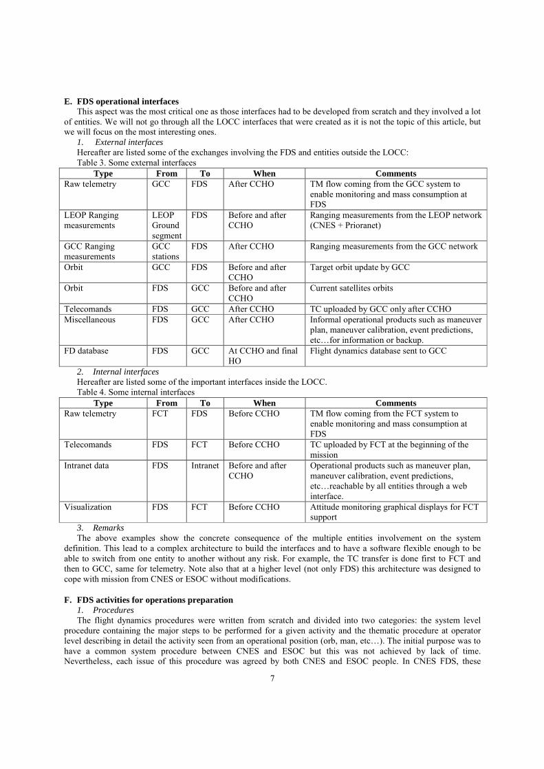
1. External interfaces Hereafter are listed some of the exchanges involving the FDS and entities outside the LOCC: Table 3. Some external interfaces
Type From To When Comments Raw telemetry GCC FDS After CCHO TM flow coming from the GCC system to
enable monitoring and mass consumption at FDS
LEOP Ranging measurements
LEOP Ground segment
FDS Before and after CCHO
Ranging measurements from the LEOP network (CNES + Prioranet)
GCC Ranging measurements
GCC stations
FDS After CCHO Ranging measurements from the GCC network
Orbit GCC FDS Before and after CCHO
Target orbit update by GCC
Orbit FDS GCC Before and after CCHO
Current satellites orbits
Telecomands FDS GCC After CCHO TC uploaded by GCC only after CCHO Miscellaneous FDS GCC After CCHO Informal operational products such as maneuver
plan, maneuver calibration, event predictions, etc…for information or backup.
FD database FDS GCC At CCHO and final HO
Flight dynamics database sent to GCC
2. Internal interfaces Hereafter are listed some of the important interfaces inside the LOCC. Table 4. Some internal interfaces
Type From To When Comments Raw telemetry FCT FDS Before CCHO TM flow coming from the FCT system to
enable monitoring and mass consumption at FDS
Telecomands FDS FCT Before CCHO TC uploaded by FCT at the beginning of the mission
Intranet data FDS Intranet Before and after CCHO
Operational products such as maneuver plan, maneuver calibration, event predictions, etc…reachable by all entities through a web interface.
Visualization FDS FCT Before CCHO Attitude monitoring graphical displays for FCT support
3. Remarks The above examples show the concrete consequence of the multiple entities involvement on the system
definition. This lead to a complex architecture to build the interfaces and to have a software flexible enough to be able to switch from one entity to another without any risk. For example, the TC transfer is done first to FCT and then to GCC, same for telemetry. Note also that at a higher level (not only FDS) this architecture was designed to cope with mission from CNES or ESOC without modifications.
F. FDS activities for operations preparation 1. Procedures The flight dynamics procedures were written from scratch and divided into two categories: the system level
procedure containing the major steps to be performed for a given activity and the thematic procedure at operator level describing in detail the activity seen from an operational position (orb, man, etc…). The initial purpose was to have a common system procedure between CNES and ESOC but this was not achieved by lack of time. Nevertheless, each issue of this procedure was agreed by both CNES and ESOC people. In CNES FDS, these
A
8
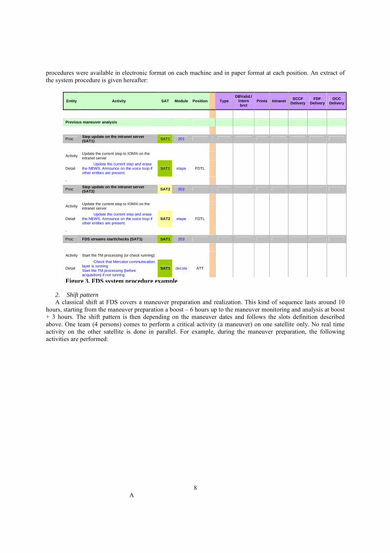
procedures were available in electronic format on each machine and in paper format at each position. An extract of the system procedure is given hereafter:
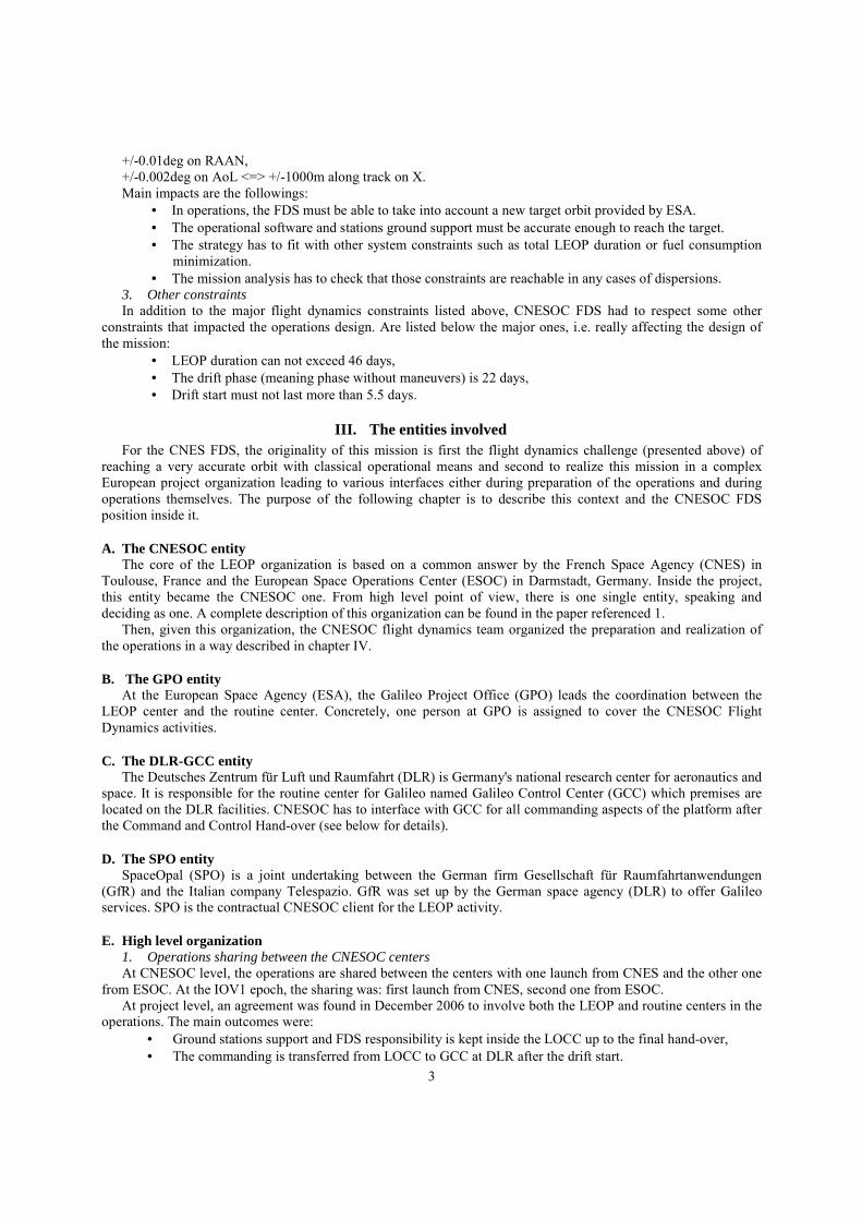
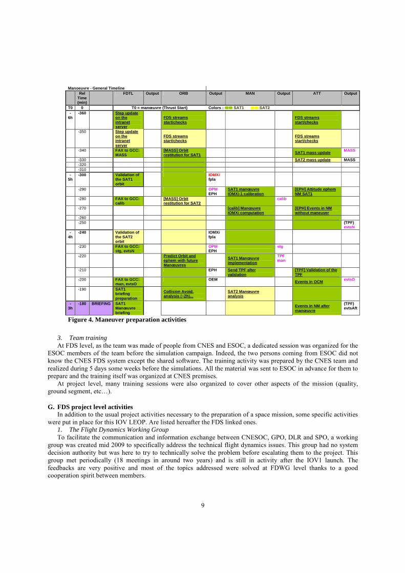
2. Shift pattern A classical shift at FDS covers a maneuver preparation and realization. This kind of sequence lasts around 10
hours, starting from the maneuver preparation a boost – 6 hours up to the maneuver monitoring and analysis at boost + 3 hours. The shift pattern is then depending on the maneuver dates and follows the slots definition described above. One team (4 persons) comes to perform a critical activity (a maneuver) on one satellite only. No real time activity on the other satellite is done in parallel. For example, during the maneuver preparation, the following activities are performed:
Entity Activity SAT Module Position Type DBValid./
intern brct
Prints Intranet SCCF
Delivery FDF
Delivery OCC
Delivery
Previous maneuver analysis
Proc Step update on the intranet server (SAT1) SAT1 201
Activity Update the current step to IOMXi on the intranet server
Detail Update the current step and erase
the NEWS. Announce on the voice loop if other entities are present.
SAT1 etape FDTL
-
Proc Step update on the intranet server (SAT2) SAT2 202
Activity Update the current step to IOMXi on the intranet server
Detail Update the current step and erase
the NEWS. Announce on the voice loop if other entities are present.
SAT2 etape FDTL
-
Proc FDS streams start/checks (SAT1) SAT1 203
Activity Start the TM processing (or check running)
Detail
Check that Mercator communication layer is running Start the TM processing (before acquisition) if not running
SAT1 decote ATT
Figure 3. FDS system procedure example
9
3. Team training At FDS level, as the team was made of people from CNES and ESOC, a dedicated session was organized for the
ESOC members of the team before the simulation campaign. Indeed, the two persons coming from ESOC did not know the CNES FDS system except the shared software. The training activity was prepared by the CNES team and realized during 5 days some weeks before the simulations. All the material was sent to ESOC in advance for them to prepare and the training itself was organized at CNES premises.
At project level, many training sessions were also organized to cover other aspects of the mission (quality, ground segment, etc…).
G. FDS project level activities In addition to the usual project activities necessary to the preparation of a space mission, some specific activities
were put in place for this IOV LEOP. Are listed hereafter the FDS linked ones. 1. The Flight Dynamics Working Group To facilitate the communication and information exchange between CNESOC, GPO, DLR and SPO, a working
group was created mid 2009 to specifically address the technical flight dynamics issues. This group had no system decision authority but was here to try to technically solve the problem before escalating them to the project. This group met periodically (18 meetings in around two years) and is still in activity after the IOV1 launch. The feedbacks are very positive and most of the topics addressed were solved at FDWG level thanks to a good cooperation spirit between members.
Manoeuvre - General Timeline Rel
Time (min)
FDTL Output ORB Output MAN Output ATT Output
T0 0 T0 = manœuvre (Thrust Start) Colors : �������� SAT1 �������� SAT2 -
6h -360 Step update
on the intranet server
FDS streams start/checks
FDS streams start/checks
-350 Step update on the intranet server
FDS streams start/checks
FDS streams start/checks
-340 FAX to GCC: MASS
[MASS] Orbit restitution for SAT1
SAT1 mass update MASS
-330 SAT2 mass update MASS -320 -310 -
5h -300 Validation of
the SAT1 orbit
IOMXi fpla
-290 OPM EPH
SAT1 manœuvre IOMXi-1 calibration
[EPH] Attitude ephem NM SAT1
-280 FAX to GCC: calib
[MASS] Orbit restitution for SAT2
calib
-270 [calib] Manœuvre IOMXi computation
[EPH] Events in NM without maneuver
-260 -250 (TPF)
evtsN -
4h -240 Validation of
the SAT2 orbit
IOMXi fpla
-230 FAX to GCC: stg, evtsN
OPM EPH
stg
-220 Predict Orbit and ephem with future Manœuvres
SAT1 Manœuvre implementation
TPF man
-210 EPH Send TPF after validation
[TPF] Validation of the TPF
-200 FAX to GCC: man, evtsO
OEM Events in OCM evtsO
-190 SAT1 briefing preparation
Collision Avoid. analysis (~2h)...
SAT2 Manœuvre analysis
-3h
-180 BRIEFING SAT1 Manœuvre briefing
Events in NM after manœuvre
(TPF) evtsAft
Figure 4. Maneuver preparation activities
10
2. The FDS cross validation A cross validation activity was requested by GPO to ensure that CNESOC FDS and DLR FDS were compatible
for critical products. This activity was consisting in a comparison of results between CNES and DLR on the following themes: orbit propagation with and without maneuver, orbit determination based on GioveB measurements, TC computation, orbital and on-board events. It was formally realized before the simulations campaign. After this cross validation’s completion, both FDS were confident in the coherency between centers.
3. Simulation campaigns Simulations covering the drift start phase (before CCHO) were under CNESOC responsibility. 18 simulations
were performed between August 2011 and October 2011. They did not involve the GCC (except one CCHO simulation).
Simulations covering the drift stop phase and involving CNES and GCC were also performed to validate a maneuver sequence. Only one simulation finally occurred.
Many internal simulations were performed (between CNES FDS and CNES FCT for example) to validate some interfaces or operational sequences in preparation of the official simulation campaigns.
V. IOV1 operations
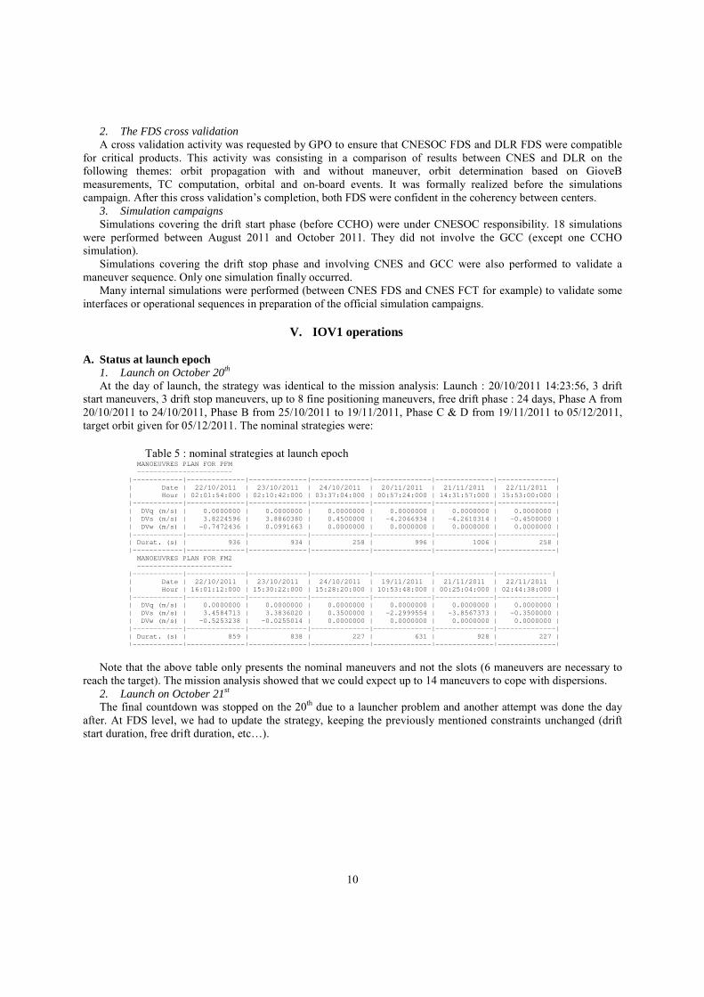
A. Status at launch epoch 1. Launch on October 20th At the day of launch, the strategy was identical to the mission analysis: Launch : 20/10/2011 14:23:56, 3 drift
start maneuvers, 3 drift stop maneuvers, up to 8 fine positioning maneuvers, free drift phase : 24 days, Phase A from 20/10/2011 to 24/10/2011, Phase B from 25/10/2011 to 19/11/2011, Phase C & D from 19/11/2011 to 05/12/2011, target orbit given for 05/12/2011. The nominal strategies were:
Note that the above table only presents the nominal maneuvers and not the slots (6 maneuvers are necessary to
reach the target). The mission analysis showed that we could expect up to 14 maneuvers to cope with dispersions. 2. Launch on October 21st The final countdown was stopped on the 20th due to a launcher problem and another attempt was done the day
after. At FDS level, we had to update the strategy, keeping the previously mentioned constraints unchanged (drift start duration, free drift duration, etc…).
Table 5 : nominal strategies at launch epoch MANOEUVRES PLAN FOR PFM ----------------------- |------------|--------------|--------------|--------------|--------------|--------------|--------------| | Date | 22/10/2011 | 23/10/2011 | 24/10/2011 | 20/11/2011 | 21/11/2011 | 22/11/2011 | | Hour | 02:01:54:000 | 02:10:42:000 | 03:37:04:000 | 00:57:24:000 | 14:31:57:000 | 15:53:00:000 | |------------|--------------|--------------|--------------|--------------|--------------|--------------| | DVq (m/s) | 0.0000000 | 0.0000000 | 0.0000000 | 0.0000000 | 0.0000000 | 0.0000000 | | DVs (m/s) | 3.8224596 | 3.8860380 | 0.4500000 | -4.2066934 | -4.2610314 | -0.4500000 | | DVw (m/s) | -0.7472436 | 0.0991663 | 0.0000000 | 0.0000000 | 0.0000000 | 0.0000000 | |------------|--------------|--------------|--------------|--------------|--------------|--------------| | Durat. (s) | 936 | 934 | 258 | 996 | 1006 | 258 | |------------|--------------|--------------|--------------|--------------|--------------|--------------| MANOEUVRES PLAN FOR FM2 ----------------------- |------------|--------------|--------------|--------------|--------------|--------------|-------------| | Date | 22/10/2011 | 23/10/2011 | 24/10/2011 | 19/11/2011 | 21/11/2011 | 22/11/2011 | | Hour | 16:01:12:000 | 15:30:22:000 | 15:28:20:000 | 10:53:48:000 | 00:25:04:000 | 02:44:38:000 | |------------|--------------|--------------|--------------|--------------|--------------|--------------| | DVq (m/s) | 0.0000000 | 0.0000000 | 0.0000000 | 0.0000000 | 0.0000000 | 0.0000000 | | DVs (m/s) | 3.4584713 | 3.3836020 | 0.3500000 | -2.2999554 | -3.8567373 | -0.3500000 | | DVw (m/s) | -0.5253238 | -0.0255014 | 0.0000000 | 0.0000000 | 0.0000000 | 0.0000000 | |------------|--------------|--------------|--------------|--------------|--------------|--------------| | Durat. (s) | 859 | 838 | 227 | 631 | 928 | 227 | |------------|--------------|--------------|--------------|--------------|--------------|--------------|
11
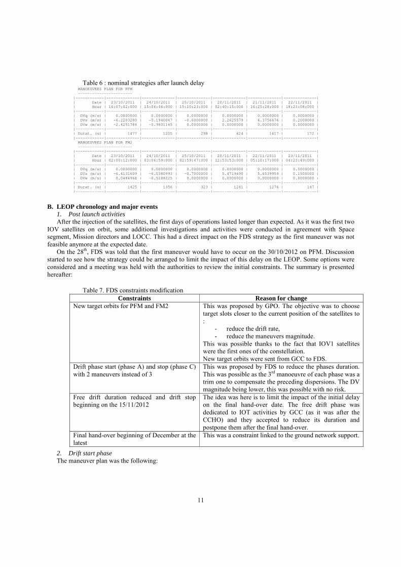
B. LEOP chronology and major events 1. Post launch activities After the injection of the satellites, the first days of operations lasted longer than expected. As it was the first two
IOV satellites on orbit, some additional investigations and activities were conducted in agreement with Space segment, Mission directors and LOCC. This had a direct impact on the FDS strategy as the first maneuver was not feasible anymore at the expected date.
On the 28th, FDS was told that the first maneuver would have to occur on the 30/10/2012 on PFM. Discussion started to see how the strategy could be arranged to limit the impact of this delay on the LEOP. Some options were considered and a meeting was held with the authorities to review the initial constraints. The summary is presented hereafter:
2. Drift start phase The maneuver plan was the following:
Table 6 : nominal strategies after launch delay MANOEUVRES PLAN FOR PFM ----------------------- |------------|--------------|--------------|--------------|--------------|--------------|--------------| | Date | 23/10/2011 | 24/10/2011 | 25/10/2011 | 20/11/2011 | 21/11/2011 | 22/11/2011 | | Hour | 16:07:02:000 | 15:06:46:000 | 15:10:23:000 | 02:40:15:000 | 16:25:28:000 | 18:23:08:000 | |------------|--------------|--------------|--------------|--------------|--------------|--------------| | DVq (m/s) | 0.0000000 | 0.0000000 | 0.0000000 | 0.0000000 | 0.0000000 | 0.0000000 | | DVs (m/s) | -6.2203280 | -5.1940047 | -0.6000000 | 2.2625579 | 6.3756676 | 0.2000000 | | DVw (m/s) | -2.4251784 | -0.9801145 | 0.0000000 | 0.0000000 | 0.0000000 | 0.0000000 | |------------|--------------|--------------|--------------|--------------|--------------|--------------| | Durat. (s) | 1477 | 1205 | 298 | 624 | 1417 | 172 | |------------|--------------|--------------|--------------|--------------|--------------|--------------| MANOEUVRES PLAN FOR FM2 ----------------------- |------------|--------------|--------------|--------------|--------------|--------------|--------------| | Date | 23/10/2011 | 24/10/2011 | 25/10/2011 | 20/11/2011 | 22/11/2011 | 23/11/2011 | | Hour | 02:00:12:000 | 03:06:59:000 | 02:59:47:000 | 12:53:53:000 | 05:10:17:000 | 04:23:49:000 | |------------|--------------|--------------|--------------|--------------|--------------|--------------| | DVq (m/s) | 0.0000000 | 0.0000000 | 0.0000000 | 0.0000000 | 0.0000000 | 0.0000000 | | DVs (m/s) | -6.4131609 | -6.0380993 | -0.7000000 | 5.4719490 | 5.6539959 | 0.1500000 | | DVw (m/s) | 0.0484968 | -0.5288225 | 0.0000000 | 0.0000000 | 0.0000000 | 0.0000000 | |------------|--------------|--------------|--------------|--------------|--------------|--------------| | Durat. (s) | 1425 | 1356 | 323 | 1241 | 1276 | 147 | |------------|--------------|--------------|--------------|--------------|--------------|--------------|
Table 7. FDS constraints modification Constraints Reason for change
New target orbits for PFM and FM2 This was proposed by GPO. The objective was to choose target slots closer to the current position of the satellites to :
- reduce the drift rate, - reduce the maneuvers magnitude.
This was possible thanks to the fact that IOV1 satellites were the first ones of the constellation. New target orbits were sent from GCC to FDS.
Drift phase start (phase A) and stop (phase C) with 2 maneuvers instead of 3
This was proposed by FDS to reduce the phases duration. This was possible as the 3rd manoeuvre of each phase was a trim one to compensate the preceding dispersions. The DV magnitude being lower, this was possible with no risk.
Free drift duration reduced and drift stop beginning on the 15/11/2012
The idea was here is to limit the impact of the initial delay on the final hand-over date. The free drift phase was dedicated to IOT activities by GCC (as it was after the CCHO) and they accepted to reduce its duration and postpone them after the final hand-over.
Final hand-over beginning of December at the latest
This was a constraint linked to the ground network support.
12
From the 30th, the operations occurred nominally and the CCHO happened on the 1st and 2nd of November for
respectively PFM and FM2. 3. Free drift phase After the CCHO, the command and control responsibility was integrally transferred to GCC. At FDS level, all
the software was already configured to support the new interfaces, without any modification. A communication test was performed during this period to ensure that everything was ready before moving to the first operations.
It has to be noted that the first operations expected after the drift phase were the drift stop maneuvers on both satellites, with GCC supporting its first critical operations. Those maneuvers of the phase C were the most critical ones: if they could not be performed, it would lead to target overshooting and consumption overcost.
During that phase, a reduced CNESOC FDS team was available on call as no critical activity was expected. This team was made of one FDTL and one ORB position. Moreover, the people from ESOC came back home during those two weeks, and were expected back on console on the 15th of November.
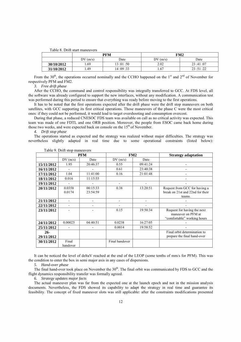
4. Drift stop phase The operations started as expected and the strategy was realized without major difficulties. The strategy was
nevertheless slightly adapted in real time due to some operational constraints (listed below):
It can be noticed the level of deltaV reached at the end of the LEOP (some tenths of mm/s for PFM). This was
the condition to enter the box in semi major axis in any cases of dispersions. 5. Hand-over phase The final hand-over took place on November the 30th. The final orbit was communicated by FDS to GCC and the
flight dynamics responsibility transfer was formally agreed. 6. Strategy updates major facts The actual maneuver plan was far from the expected one at the launch epoch and not in the mission analysis
documents. Nevertheless, the FDS showed its capability to adapt the strategy in real time and guarantee its feasibility. The concept of fixed maneuver slots was still applicable: after the constraints modifications presented
Table 9. Drift stop maneuvers PFM FM2 Strategy adaptation DV (m/s) Date DV (m/s) Date
15/11/2012 1.95 20:46:37 0.55 09:41:24 - 16/11/2012 - - 0.61 23:40:38 - 17/11/2012 1.04 11:41:00 0.16 21:01:48 - 18/11/2012 0.016 11:15:55 - 19/11/2012 - - - - - 20/11/2012 0.0358
0.0174 00:15:33 23:54:59
0.38 13:20:51 Request from GCC for having a break on 21st and 22nd for their
teams. 21/11/2012 - - - - - 22/11/2012 - - - - - 23/11/2012 - - 0.15 19:50:34 Request for having the next
maneuver on PFM at “comfortable” working hours
24/11/2012 0.00025 04:40:51 0.0238 16:27:05 - 25/11/2012 - - 0.0014 19:58:52 -
26-29/11/2012
Final orbit determination to prepare the final hand-over
30/11/2012 Final handover
Final handover
Table 8. Drift start maneuvers PFM FM2 DV (m/s) Date DV (m/s) Date
30/10/2012 1.69 13 :01 :50 2.02 23 :41 :07 31/10/2012 1.49 14 :09 :33 1.67 23 :51 :22
13
above, a new maneuver slot schema was given to the teams to arrange the operations. This schema was respected up to the final hand-over in the strategy updates.
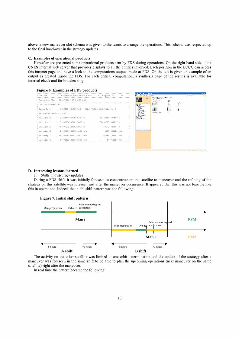
C. Examples of operational products Hereafter are presented some operational products sent by FDS during operations. On the right hand side is the
CNES internal web server that provides displays to all the entities involved. Each position in the LOCC can access this intranet page and have a look to the computations outputs made at FDS. On the left is given an example of an output as created inside the FDS. For each critical computation, a synthesis page of the results is available for internal check and for broadcasting.
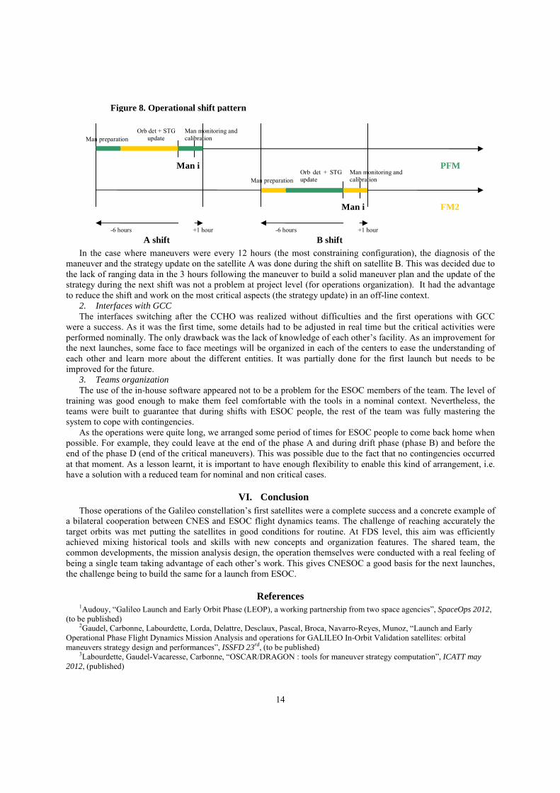
D. Interesting lessons learned 1. Shifts and strategy updates During a FDS shift, it was initially foreseen to concentrate on the satellite to maneuver and the refining of the
strategy on this satellite was foreseen just after the maneuver occurrence. It appeared that this was not feasible like this in operations. Indeed, the initial shift pattern was the following:
The activity on the other satellite was limited to one orbit determination and the update of the strategy after a
maneuver was foreseen in the same shift to be able to plan the upcoming operations (next maneuver on the same satellite) right after the maneuver.
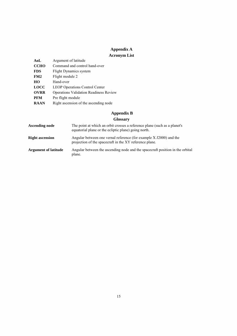
In real time the pattern became the following:
Figure 6. Examples of FDS products ******************************************************************************** * OOP FDS * Reference Time Frame : UTC * Request ID : 99 * ******************************************************************************** * Execution Time : 22/07/2003 13:28:23:000 * ******************************************************************************** * ORBITAL PARAMETERS : * * * * Epoch Date : 5.2842564854803e+04 (22/07/2003 13:33:23:455 ) * * * * Reference frame : J2000 * * * * Position X : -2.8464790677589e+07 m -28464790.677589 m * * * * Position Y : -3.0890387904297e+07 m -30890387.904297 m * * * * Position Z : -6.8072323496527e+04 m -68072.323497 m * * * * Velocity X : 1.0958958212951e+03 m/s 1095.895821 m/s * * * * Velocity Y : -1.2651859465133e+03 m/s -1265.185947 m/s * * * * Velocity Z : 5.7715228859667e+01 m/s 57.715229 m/s * ********************************************************************************
PFM
FM2
Man i
Man i
-6 hours +3 hours
Man preparation Man monitoring and calibration Orb det
Man monitoring and calibration Orb det Man preparation
-6 hours +3 hours
A shift B shift
Figure 7. Initial shift pattern
14
In the case where maneuvers were every 12 hours (the most constraining configuration), the diagnosis of the
maneuver and the strategy update on the satellite A was done during the shift on satellite B. This was decided due to the lack of ranging data in the 3 hours following the maneuver to build a solid maneuver plan and the update of the strategy during the next shift was not a problem at project level (for operations organization). It had the advantage to reduce the shift and work on the most critical aspects (the strategy update) in an off-line context.
2. Interfaces with GCC The interfaces switching after the CCHO was realized without difficulties and the first operations with GCC
were a success. As it was the first time, some details had to be adjusted in real time but the critical activities were performed nominally. The only drawback was the lack of knowledge of each other’s facility. As an improvement for the next launches, some face to face meetings will be organized in each of the centers to ease the understanding of each other and learn more about the different entities. It was partially done for the first launch but needs to be improved for the future.
3. Teams organization The use of the in-house software appeared not to be a problem for the ESOC members of the team. The level of
training was good enough to make them feel comfortable with the tools in a nominal context. Nevertheless, the teams were built to guarantee that during shifts with ESOC people, the rest of the team was fully mastering the system to cope with contingencies.
As the operations were quite long, we arranged some period of times for ESOC people to come back home when possible. For example, they could leave at the end of the phase A and during drift phase (phase B) and before the end of the phase D (end of the critical maneuvers). This was possible due to the fact that no contingencies occurred at that moment. As a lesson learnt, it is important to have enough flexibility to enable this kind of arrangement, i.e. have a solution with a reduced team for nominal and non critical cases.
VI. Conclusion Those operations of the Galileo constellation’s first satellites were a complete success and a concrete example of
a bilateral cooperation between CNES and ESOC flight dynamics teams. The challenge of reaching accurately the target orbits was met putting the satellites in good conditions for routine. At FDS level, this aim was efficiently achieved mixing historical tools and skills with new concepts and organization features. The shared team, the common developments, the mission analysis design, the operation themselves were conducted with a real feeling of being a single team taking advantage of each other’s work. This gives CNESOC a good basis for the next launches, the challenge being to build the same for a launch from ESOC.
References 1Audouy, “Galileo Launch and Early Orbit Phase (LEOP), a working partnership from two space agencies”, SpaceOps 2012,
(to be published) 2Gaudel, Carbonne, Labourdette, Lorda, Delattre, Desclaux, Pascal, Broca, Navarro-Reyes, Munoz, “Launch and Early
Operational Phase Flight Dynamics Mission Analysis and operations for GALILEO In-Orbit Validation satellites: orbital maneuvers strategy design and performances”, ISSFD 23rd, (to be published)
3Labourdette, Gaudel-Vacaresse, Carbonne, “OSCAR/DRAGON : tools for maneuver strategy computation”, ICATT may 2012, (published)
PFM
FM2
Man i
Man i
-6 hours +1 hour
Man preparation Man monitoring and calibration
Orb det + STG update
Man monitoring and calibration
Orb det + STG update Man preparation
-6 hours +1 hour
A shift B shift
Figure 8. Operational shift pattern
15
Appendix A Acronym List
AoL Argument of latitude CCHO Command and control hand-over FDS Flight Dynamics system FM2 Flight module 2 HO Hand-over LOCC LEOP Operations Control Center OVRR Operations Validation Readiness Review PFM Pre flight module RAAN Right ascension of the ascending node
Appendix B Glossary
Ascending node The point at which an orbit crosses a reference plane (such as a planet's equatorial plane or the ecliptic plane) going north.
Right ascension Angular between one vernal reference (for example X J2000) and the projection of the spacecraft in the XY reference plane.
Argument of latitude Angular between the ascending node and the spacecraft position in the orbital plane.