Embed Size (px)
Citation preview
4
ANNEXES C’SPACE 2018
LES PROJETS CANSAT
LES PROJETS CANSAT
4
ANNEXES C’SPACE 2018
5
ANNEXES C’SPACE 2018
LES PROJETS CANSAT LES PROJETS CANSAT
Diseño y desarrollo de un prototipo de CanSat para recolección de parámetros atmosféricos.
Jean Vargas Departamento de Ingeniería Electrónica
Universidad Nacional de Ingeniería Lima, Perú
Waldir Flores Departamento de Ingeniería Mecánica
Universidad Nacional de Ingeniería Lima, Perú
Danny Ruiz Departamento de Ingeniería Mecánica
Universidad Nacional de Ingeniería Lima, Perú
Adriana Ticona
Departamento de Ingeniería Electrónica Universidad Nacional de Ingeniería
Lima, Perú [email protected]
José Espinoza
Departamento de Ingeniería Electrónica Universidad Nacional de Ingeniería
Lima, Perú [email protected]
Christian Caballero
Departamento de Ingeniería Mecánica Universidad Nacional de Ingeniería
Lima, Perú [email protected]
Resumen—la tecnología aeroespacial constituye un sector muy importante en el mundo y en la realidad de cada país. Perú no es ajeno a esta realidad, la Comisión Nacional de Investigación y Desarrollo Aeroespacial , CONIDA, viene realizando avances, que se ven reflejados en cohetes capaces de estudiar la mediana atmósfera, control y procesamiento de imágenes del Peru-Sat 1. En instituciones universitarias como la Universidad Nacional de Ingeniería promueve el desarrollo de estas tecnologías, por medio de UNISEC-PERU y TEAM CANSAT-PERU y con el apoyo de instituciones internacionales cómo UNISEC-GLOBAL y PLANÈTE SCIENCES; empleando la metodología CANSAT. esta consiste en el diseño y validación de un "satélite" miniaturizado en el
volumen de una lata de soda, por lo general tiene la misión de recoger datos, efectuar retornos controlados o en algunas ocasiones cumplir algún perfil de misión predeterminado. En este artículo se expondrá el diseño y los resultados de la construcción de un prototipo de CANSAT el cual realiza la toma y transmisión de datos atmosféricos, ubicación gps, parámetros cinemáticos y el almacenamiento de imágenes en una sd card; que serán capturadas en descenso. Además de desplegar un sistema de recarga fotovoltaico y mecanismo de eyección de un astronauta miniatura. Keywords-Mosaicing, Sensor, Cansat, aeroespacial,fotovoltaico
6
ANNEXES C’SPACE 2018
LES PROJETS CANSAT
I. INTRODUCCIÓN La ingeniería aeroespacial es
multidisciplinaria por lo que incluye conceptos de diferentes especialidades en este alcance, permitiendo un amplio campo de investigación. Actualmente, en una misión CanSat se toman datos atmosféricos (presión, humedad, temperatura, etc), y también se incluye una cámara la cual toma el espectro necesario según las necesidades de cada misión, para que a partir de las imágenes se obtenga información más detallada como el área del terreno de aterrizaje, tipo de suelo, predominio de áreas verdes, espectros de cuerpos a estudiar, entre otros.
La estructura del artículo consta de la definición de los objetivos, la definición y diseño de cada subsistema, la integración de los subsistemas en lo que es el diseño preliminar y los resultados y conclusiones obtenidos del diseño final. En la fase que contempla la definición conceptual se define la misión del CanSat y los subsistemas tales como la mecánica, electrónica, control y procesamiento de imágenes. El diseño prosigue con la selección de los componentes electrónicos y sistemas embebidos, el cálculo del requerimiento energético, modelado del sistema de control, diseño mecánico de la estructura soporte y sistemas de accionamiento mecánico, así como la aerodinámica del cobertor, paracaídas y finalmente el procesamiento de las imágenes obtenidas.
En el acápite siguiente se muestra la integración del CanSat ajustando algunos parámetros de diseño para permitir el trabajo en conjunto de los subsistemas. Finalmente, un resumen de los resultados.
II. OBJETIVOS II.1 Objetivos Generales El Diseño y desarrollo de un sistema de recolección de datos atmosférico y toma de imágenes para posteriormente procesamiento basado en la tecnología CanSat
III.2 Objetivos Específicos
1. Obtener una estructura mecánica lo suficientemente rígida para las condiciones del lanzamiento.
2. Diseñar y fabricar placas electrónicas y
el sistema de alimentación para permitir la toma de datos atmosféricos en caída libre.
3. Obtener una imagen panorámica del
relieve a partir de fotos tomadas por el vehículo en el descenso.
4. Diseñar y fabricar un mecanismo
desplegable de celdas solares para mejorar la autonomía de carga eléctrica al sistema.
III. DISEÑO El diseño del Cansat se trabajó por subsistemas:
1. Mecánica 2. Electrónica de sensado. 3. Control 4. Telemetría.
El desarrollo de los subsistemas se detalla a continuación III.1 Mecánica La mecánica del Cansat comprende la estructura soporte, mecanismo de eyección del paracaidista, sistema de despliegue de celdas solares y el paracaídas. cada una de ellas se diseñaron optimizadas a las condiciones de la misión del CanSat.
A. Estructura soporte La estructura permite la correcta disposición de los dispositivos electrónicos. La
7
ANNEXES C’SPACE 2018
LES PROJETS CANSAT LES PROJETS CANSAT
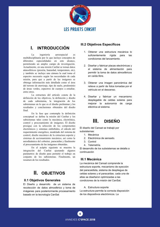
manufactura se logró con una impresora 3D, en material plástico ABS. Además de la distribución, la estructura salvaguarda la integridad de los componentes internos, por lo que en el diseño se realizó un análisis de rigidez mediante el método de elementos finitos a las condiciones más críticas de trabajo, para asegurarnos que logre aterrizar a 5m/s.
Figura 1. Simulación Fem de la estructura. resultados de deformación
Figura 2. Disposición de los componentes electrónicos.
B. Sistema de despliegue de celdas solares
El sistema permite la liberación de un soporte expandible que permite orientar celdas solares para poder recolectar energía para los sistemas electrónicos. El sistema es accionado por unos resortes torsionales y liberado por el calentamiento de un cable de nicrom.
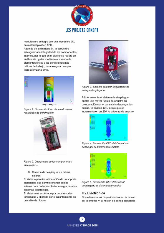
Figura 3. Sistema colector fotovoltaico de energía desplegado. Adicionalmente el sistema de despliegue aporta una mayor fuerza de arrastre en comparación con el cansat sin desplegar las celdas. El análisis CFD arrojó que se incrementa en un 260 % la fuerza de arrastre.
Figura 4. Simulación CFD del Cansat sin desplegar el sistema fotovoltaico
Figura 5. Simulación CFD del Cansat desplegado el sistema fotovoltaico II.2 Electrónica Considerando los requerimientos en la misión de telemetría y la misión de sonda planetaria
8
ANNEXES C’SPACE 2018
LES PROJETS CANSAT
se implementó el hardware del CanSat con los siguientes componentes que serán los adecuados para lo pedido. La parte principal del CanSat es un Raspberry Pi Zero, la cual se eligió aprovechando su pequeño tamaño y su capacidad de procesamiento, así también es la fuente de alimentación de los sensores y el módulo Lora. Los componentes electrónicos serán integrados en una placa electrónica que se alimenta de la fuente a una tensión regulada a 5v. La lista de componentes se encuentra en la siguiente tabla
Components Function
Raspberry pi zero Flight Computer
BME-280 Atmospheric pressure, temperature and humidity
MQ-7 Carbon monoxide
MQ-135 Nitrogen oxides
GY-521 MPU6050 accelerometer
Módulo GPS NEO-6M
Latitude and longitude
Módulo Transceiver LORA 433MHz XL1278
RF transmitter
Micro- SD Almacenamiento de datos
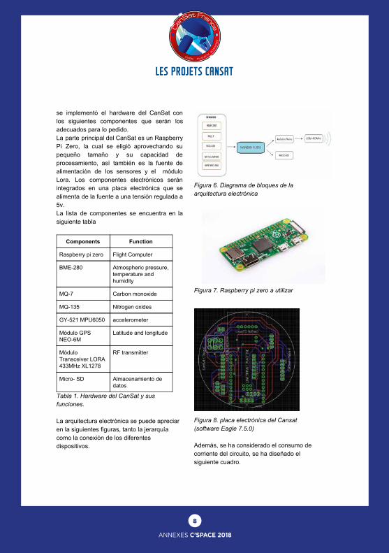
Tabla 1. Hardware del CanSat y sus funciones. La arquitectura electrónica se puede apreciar en la siguientes figuras, tanto la jerarquía como la conexión de los diferentes dispositivos.
Figura 6. Diagrama de bloques de la arquitectura electrónica
Figura 7. Raspberry pi zero a utilizar
Figura 8. placa electrónica del Cansat (software Eagle 7.5.0) Además, se ha considerado el consumo de corriente del circuito, se ha diseñado el siguiente cuadro.

9
ANNEXES C’SPACE 2018
LES PROJETS CANSAT LES PROJETS CANSAT
Tabla 2. consumo de energía y corriente de la placa. La distribución de energía se muestra a continuación en el siguiente esquema.
Figure 9. Diagrama energía del sistema. II.3 Control El Sistema de control permite el correcto funcionamiento de los actuadores, sensores y la adquisición de imágenes. Inicializando todos los sistemas, y activando, según la condición de lectura del acelerómetro, los sistemas mecánicos de despliegue y eyección, a través del cable de nicrom. El siguiente esquema muestra el diagrama de flujo de la lógica del sistema de control.
Figure 10. Diagrama de flujo del sistema de control
A. Adquisicion de Imagenes: El proceso de adquisición de imágenes se implementó con la placa raspberry pi zero y su módulo cámara V2.
Figure 11. Módulo cámara V2 de Raspberry Pi La raspberry pi cuenta con un algoritmo que otorga un intervalo de tiempo (t) para el secuenciado de toma de imágenes. El intervalo de tiempo dependerá de la altura a la que éste sea soltado y la velocidad de descenso estimada.
10
ANNEXES C’SPACE 2018
LES PROJETS CANSAT
Figure 12. Script algoritmo adquisición de
imágenes.
B. Postprocesamiento de imágenes En el post procesamiento se busca obtener una única imagen general de la zona de lanzamiento a partir de las imágenes obtenidas durante el aterrizaje. Para ellos es que se realiza una serie de filtros a fin de corregir los errores presentes en la captura de imagen, con lo que se puede llegar a integrar todas las imágenes mediante un proceso denominado “Mosaicing”.
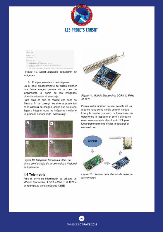
Figure 13. Imágenes tomadas a 20 m. de altura en el estadio de la Universidad Nacional de Ingeniería II.4 Telemetría Para el envío de información se utilizará un Módulo Transceiver LORA 433MHz XL1278 a en reemplazo de los módulos XBEE.
Figure 14. Módulo Transceiver LORA 433MHz XL1278 Para nuestra facilidad de uso, se utilizará un arduino nano como medio entre el módulo Lora y la raspberry pi zero. La transmisión de datos entre la raspberry pi zero y el arduino nano será mediante el protocolo SPI, para luego posteriormente enviar la data por el módulo Lora.
Figure 15. Proceso para el envió de datos de los sensores
11
ANNEXES C’SPACE 2018
LES PROJETS CANSAT LES PROJETS CANSAT
.
Acknowledgment Cada miembro del laboratorio "Smart-Machines". El director del Centro de tecnologías de información y comunicación (CTIC-UNI) Alonso tenorio Trigoso por el apoyo brindado.
References [1] Thoraya Obaid, Haliemah Rashed, Ali Abu El
Nour, Muhammad Rehan, Mussab Muhammad Saleh, and Eason, Mohammed Tarique, “Zig-Bee based voice controlled wireless smart home system,” International Journal of Wireless & Mobile Networks (IJWMN) Vol. 6, No. 1, February 2014. [2] Francesca Cuomo, Sara Della Luna, Ugo MonacoI.S, Tommaso Melodia “Routing in Zig-Bee: benefits from exploiting the IEEE 802.15.4 association tree,” publication in the ICC 2007 proceedings. [3]i-micro.com/pdf/articulos/spi.pdf [4] “Arduino Forum” https://forum.arduino.cc/. [5] “Módulo Transceiver LORA 433MHz XL1278, ”https://naylampmechatronics.com/inalambrico/332-modulo-transceiver-lora-433mhz-xl1278.html [6]“IMU-LSM9DS1”,https://www.sparkfun.com/products/13284. [7]“BME-280SENSOR”,https://www.sparkfun.com/products/13676 [8]“MQSENSOR”,https://playground.arduino.cc/Main/MQGasSensors [9]“Módulo GPS NEO-6M”, https://naylampmechatronics.com/sensores-posicion-inerciales-gps/106-modulo-gps.html?search_query=gps&results=12 [10]“moduloMicro-SD”https://www.sparkfun.com/products/544 [5] T, Nicosevici, Efficient 3D Scene Modeling and Moaicing, “Thesis Doctoral”, University of Girona, 2009. [6] R. Prados, Image Blending techniques and their Aplication in Underwater Mosaicing, “PhD Thesis”.,University of Girona, 2013. [7] C, García, Umbrales de discriminación cromática y su aplicación a un algoritmo de foltraje de imágenes digitales,”M. Sc Vision”, Universidad de Alicante, 2008. [8]“raspberry pi community” https://www.raspberrypi.org/help/
[9] N, Banic, “Improving the White Patch Method by Subsamplig, Department of Electronic System and Information Processing University of Zagreb”, 2014. [10] A, Kaspers, Blob Detection, Biomedical Image Sciences Image Science Institute UMC Utrecht, [11] D. Kornack and P. Rakic, “Cell Proliferation without Neurogenesis in Adult Primate Neocortex,” Science, vol. 294, Dec. 2001, pp. 2127-2130, doi:10.1126/science.1065467. Article in a conference proceedings: [12] H. Goto, Y. Hasegawa, and M. Tanaka, “Efficient Scheduling Focusing on the Duality of MPL Representatives,” Proc. ASME Symp. Computational Intelligence in Scheduling (SCIS 07), ASME Press, Dec. 2007, pp. 57-64, doi:10.1109/SCIS.2007.357670.
12
ANNEXES C’SPACE 2018
LES PROJETS CANSAT
Summary- The Cansat is a project made by student. Its aim is to create a satellite which fit in a can “can’ (1 Liter) and follow different “mission”. The mandatory mission is to deploy a base on the ground. The second mission we choose is to measure different variable as the temperature, altitude, GPS’s data and the luminosity.
I Introduction: The context:The Cansat was released in the IUT of Nîmes and Supervised by Mr Giamarchi. It’s a school project that unwound on the whole year and to finalized it we choose to participate at the Cansat challenge. The challenge take part the 15th to the 22nd of July near Tarbes. A CAN !; Our satellites have to fit in a can of one liter because initially it have to be launched inside a FUSEX and so fit in. It’s not easy to dimension a satellite this small!
II The missions: Mandatory mission; The mandatory mission is to deploy a base on the ground when the Cansat is landing. This base have to fit in the one liter can with the others components and expend itself out of the can and ensure a smooth landing for the satellite. To realize this mission we use servo-motors coupled with a mechanism that release the base made by 4 legs. Secondary mission: We choose as a the secondary mission to measure the temperature, the altitude,the luminosity and get GPS’s data. To fulfill this mission we use different sensors connected to the microcontroller by I2C a serial and synchronous communication. It’s a free mission but we wanted to do it like that to get data to understand how a real landing is done and how can we improve our Cansat.
13
ANNEXES C’SPACE 2018
LES PROJETS CANSAT LES PROJETS CANSAT
Summary- The Cansat is a project made by student. Its aim is to create a satellite which fit in a can “can’ (1 Liter) and follow different “mission”. The mandatory mission is to deploy a base on the ground. The second mission we choose is to measure different variable as the temperature, altitude, GPS’s data and the luminosity.
I Introduction: The context:The Cansat was released in the IUT of Nîmes and Supervised by Mr Giamarchi. It’s a school project that unwound on the whole year and to finalized it we choose to participate at the Cansat challenge. The challenge take part the 15th to the 22nd of July near Tarbes. A CAN !; Our satellites have to fit in a can of one liter because initially it have to be launched inside a FUSEX and so fit in. It’s not easy to dimension a satellite this small!
II The missions: Mandatory mission; The mandatory mission is to deploy a base on the ground when the Cansat is landing. This base have to fit in the one liter can with the others components and expend itself out of the can and ensure a smooth landing for the satellite. To realize this mission we use servo-motors coupled with a mechanism that release the base made by 4 legs. Secondary mission: We choose as a the secondary mission to measure the temperature, the altitude,the luminosity and get GPS’s data. To fulfill this mission we use different sensors connected to the microcontroller by I2C a serial and synchronous communication. It’s a free mission but we wanted to do it like that to get data to understand how a real landing is done and how can we improve our Cansat.
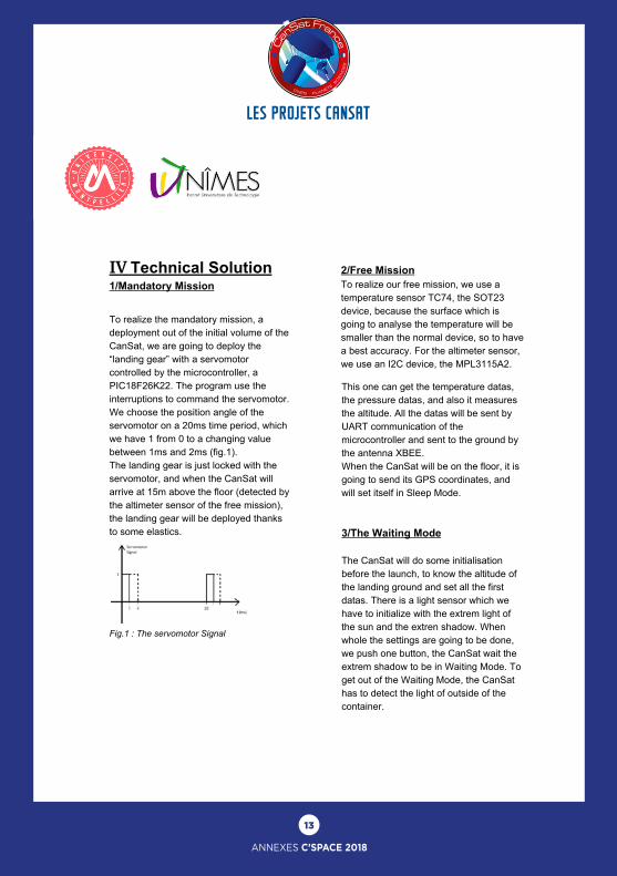
IV Technical Solution 1/Mandatory Mission To realize the mandatory mission, a deployment out of the initial volume of the CanSat, we are going to deploy the “landing gear” with a servomotor controlled by the microcontroller, a PIC18F26K22. The program use the interruptions to command the servomotor. We choose the position angle of the servomotor on a 20ms time period, which we have 1 from 0 to a changing value between 1ms and 2ms (fig.1). The landing gear is just locked with the servomotor, and when the CanSat will arrive at 15m above the floor (detected by the altimeter sensor of the free mission), the landing gear will be deployed thanks to some elastics.
Fig.1 : The servomotor Signal 2/Free Mission To realize our free mission, we use a temperature sensor TC74, the SOT23 device, because the surface which is going to analyse the temperature will be smaller than the normal device, so to have a best accuracy. For the altimeter sensor, we use an I2C device, the MPL3115A2.
This one can get the temperature datas, the pressure datas, and also it measures the altitude. All the datas will be sent by UART communication of the microcontroller and sent to the ground by the antenna XBEE. When the CanSat will be on the floor, it is going to send its GPS coordinates, and will set itself in Sleep Mode. 3/The Waiting Mode The CanSat will do some initialisation before the launch, to know the altitude of the landing ground and set all the first datas. There is a light sensor which we have to initialize with the extrem light of the sun and the extren shadow. When whole the settings are going to be done, we push one button, the CanSat wait the extrem shadow to be in Waiting Mode. To get out of the Waiting Mode, the CanSat has to detect the light of outside of the container.
14
ANNEXES C’SPACE 2018
LES PROJETS CANSAT
Summary- The Cansat is a project made by student. Its aim is to create a satellite which fit in a can “can’ (1 Liter) and follow different “mission”. The mandatory mission is to deploy a base on the ground. The second mission we choose is to measure different variable as the temperature, altitude, GPS’s data and the luminosity.
I Introduction: The context:The Cansat was released in the IUT of Nîmes and Supervised by Mr Giamarchi. It’s a school project that unwound on the whole year and to finalized it we choose to participate at the Cansat challenge. The challenge take part the 15th to the 22nd of July near Tarbes. A CAN !; Our satellites have to fit in a can of one liter because initially it have to be launched inside a FUSEX and so fit in. It’s not easy to dimension a satellite this small!
II The missions: Mandatory mission; The mandatory mission is to deploy a base on the ground when the Cansat is landing. This base have to fit in the one liter can with the others components and expend itself out of the can and ensure a smooth landing for the satellite. To realize this mission we use servo-motors coupled with a mechanism that release the base made by 4 legs. Secondary mission: We choose as a the secondary mission to measure the temperature, the altitude,the luminosity and get GPS’s data. To fulfill this mission we use different sensors connected to the microcontroller by I2C a serial and synchronous communication. It’s a free mission but we wanted to do it like that to get data to understand how a real landing is done and how can we improve our Cansat.
V The team: Benjamin Barbier - Leader Tristan Herpsont Horrillo - co-leader Frederic Giamarchi - supervisor The team is made by two students (Tristan & Benjamin) and a teacher Mr Giamarchi.
V Conclusion : To conclude we can say that the Cansat is a really interesting challenge because it gather electronic and mechanic, and it permit for everyone to launch and see their satellite fly even if it’s made by an engineering school or an IUT. We impatient to see all the realisation and if our project will work ! We would like to specially thanks Mr Giamarchi for his help during all the project

15
ANNEXES C’SPACE 2018
LES PROJETS CANSAT LES PROJETS CANSAT
Summary- The Cansat is a project made by student. Its aim is to create a satellite which fit in a can “can’ (1 Liter) and follow different “mission”. The mandatory mission is to deploy a base on the ground. The second mission we choose is to measure different variable as the temperature, altitude, GPS’s data and the luminosity.
I Introduction: The context:The Cansat was released in the IUT of Nîmes and Supervised by Mr Giamarchi. It’s a school project that unwound on the whole year and to finalized it we choose to participate at the Cansat challenge. The challenge take part the 15th to the 22nd of July near Tarbes. A CAN !; Our satellites have to fit in a can of one liter because initially it have to be launched inside a FUSEX and so fit in. It’s not easy to dimension a satellite this small!
II The missions: Mandatory mission; The mandatory mission is to deploy a base on the ground when the Cansat is landing. This base have to fit in the one liter can with the others components and expend itself out of the can and ensure a smooth landing for the satellite. To realize this mission we use servo-motors coupled with a mechanism that release the base made by 4 legs. Secondary mission: We choose as a the secondary mission to measure the temperature, the altitude,the luminosity and get GPS’s data. To fulfill this mission we use different sensors connected to the microcontroller by I2C a serial and synchronous communication. It’s a free mission but we wanted to do it like that to get data to understand how a real landing is done and how can we improve our Cansat.
IV Technical Solution 1/Mandatory Mission To realize the mandatory mission, a deployment out of the initial volume of the CanSat, we are going to deploy the “landing gear” with a servomotor controlled by the microcontroller, a PIC18F26K22. The program use the interruptions to command the servomotor. We choose the position angle of the servomotor on a 20ms time period, which we have 1 from 0 to a changing value between 1ms and 2ms (fig.1). The landing gear is just locked with the servomotor, and when the CanSat will arrive at 15m above the floor (detected by the altimeter sensor of the free mission), the landing gear will be deployed thanks to some elastics.
Fig.1 : The servomotor Signal 2/Free Mission To realize our free mission, we use a temperature sensor TC74, the SOT23 device, because the surface which is going to analyse the temperature will be smaller than the normal device, so to have a best accuracy. For the altimeter sensor, we use an I2C device, the MPL3115A2.
This one can get the temperature datas, the pressure datas, and also it measures the altitude. All the datas will be sent by UART communication of the microcontroller and sent to the ground by the antenna XBEE. When the CanSat will be on the floor, it is going to send its GPS coordinates, and will set itself in Sleep Mode. 3/The Waiting Mode The CanSat will do some initialisation before the launch, to know the altitude of the landing ground and set all the first datas. There is a light sensor which we have to initialize with the extrem light of the sun and the extren shadow. When whole the settings are going to be done, we push one button, the CanSat wait the extrem shadow to be in Waiting Mode. To get out of the Waiting Mode, the CanSat has to detect the light of outside of the container.
16
ANNEXES C’SPACE 2018
LES PROJETS CANSAT
Nous réalisons le projet CanSat dans le cadre de notre dernière année de DUT Génie Electrique Informatique Industrielle. C’est un projet qui s’inscrit dans notre programme d’étude car il permet de faire de l’électronique, de la programmation et de la mécanique. Notre problématique, était de créer une canette qui peut être lâchée d’une hauteur de 150 m avec un volume d’un litre et pouvant réaliser : un déploiement, une prise et restitution de données. Missions réalisées en accord avec le thème de l’année la vie de l’Homme dans l’espace.
Notre Objectif est d’une part de finaliser le projet en appliquant nos connaissances et en cherchant à acquérir de nouvelles connaissances théoriques et d’autre part d’aller le plus loin dans la compétition. Nous avons dans un premier temps fait un travail de recherche pour répondre aux caractéristiques techniques demandées, et aboutir aux solutions. Des solutions techniques pour chaque mission ont été définies.
Pour suivre le cahier des charges nous devons donc respecter un poids de 1 kg pour un volume de 1 L, soit 20 cm de hauteur et 80 mm de diamètre. Pour répondre à cette problématique nous avons décidé d’imprimer la canette en matière plastique, à partir d’un modèle modélisé sur SolidWorks, en gardant des dimensions plus petites que celles qu’impose le Cahier des Charges. Nous avons choisi le PLA, acide polylactique car c’est une matière plastique faite à partir d’amidon et donc très malléable mais aussi pour des raisons de compromis entre le poids léger et la résistance aux chocs que va recevoir la canette à l’atterrissage. Pour le déploiement de la canette, nous avons décidé de commander l’ouverture par un électro-aimant et afin de s’assurer que cela fonctionne nous avons renforcé le système avec des ressorts au niveau des charnières.
Pour l’éjection, nous utilisons la même solution technique que pour l’ouverture des portes. Pour assurer le bon fonctionnement électrique du système nous utilisons des diodes de roue libre, dans le but de protéger le transistor. Le transistor, permet de contrôler l’électroaimant avec la tension de 5 V du microcontrôleur car la tension requise pour que le
transistor soit passant est de 4 V. Ainsi, même si la carte ne débite pas 5 V, l’électroaimant pourra être commandé.
Dans le but de traiter des données, le plus cohérente possible avec le thème, la vie de l’homme dans l’espace, nous avons choisi trois capteurs, ADXL345, capteur d’accélération, BME280, capteur d’humidité, de pression atmosphérique et de température, nous les avons choisis sur plusieurs critère l’étendue de mesure, la précision, la fidélité, le temps de réponse et le bus de communication.
Pour programmer les capteurs nous avions choisi une PSoC 5LP et le logiciel PSoC Creator (Programmable System On Chip) avec l’utilisation d’un bus I2C (Inter Integrated Circuit) qui est un bus série synchrone, une programmation nouvelle pour nous et qui permet de faire communiquer des composants électroniques très divers grâce à seulement 3 fils.
Pour répondre aux problématiques de
traitement des données nous nous sommes d’abord concentrés sur la communication. Pour cela nous avons opté pour une transmission sans fil via un module XBee. Piloté par le microcontrôleur, il permet d’envoyer des données vers un autre module connecté quant à lui à un PC. Après vérification, la puissance d’émission est réglable et nous permettra de nous plier au cahier des charges de la compétition. En parallèle, nous avons décidé de mettre en place un système d’enregistrement des données relevées par les capteurs, au cas où la connexion sans fil ne fonctionne pas lors du lâcher. Pour se faire, nous avons décidé d’ajouter une carte Adafruit Micro-SD card breakout board. Pour la caméra, nous avons choisi la caméra u-CAM III qui possède nativement tout ce qui est nécessaire pour pouvoir traiter les images. Il faut ensuite les enregistrer sur la carte SD.
17
ANNEXES C’SPACE 2018
LES PROJETS CANSAT LES PROJETS CANSAT
Description Scientifique du Cansat Projet d’étude 95 : Conception et construction d’un
CanSat
ARNOULD Tiphaine BAI Yue
MRABET Ilyes SOUALA Dhann
YANG Rui
20 Avril 2018
18
ANNEXES C’SPACE 2018
LES PROJETS CANSAT
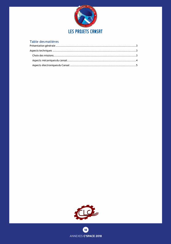
Table des matières Présentation générale ................................................................................... 3
Aspects techniques ...................................................................................... 3
Choix des missions ..................................................................................... 3
Aspects mécaniques du cansat ....................................................................... 4
Aspects électroniques du Cansat .................................................................... 5
Description Scientifique du Cansat Projet d’étude 95 : Conception et construction d’un
CanSat
ARNOULD Tiphaine BAI Yue
MRABET Ilyes SOUALA Dhann
YANG Rui
20 Avril 2018
19
ANNEXES C’SPACE 2018
LES PROJETS CANSAT LES PROJETS CANSAT
Présentation générale : Ce projet d’étude se déroule au sein de l’école Centrale de Lyon, une école d’ingénieur
située dans la ville d’Écully en région lyonnaise. L’idée sous-tendant des projets d’études est de placer les étudiants dans un véritable contexte de conduite de projet pendant la durée de leur première année au sein de l’école pour mesurer ce que représente les impératifs d’un projet défini dans le cahier des charges et astreint au respect d’un délai de livraison . Pour les accompagner dans ce projet, un financement à hauteur de 300 euros est donné à chaque équipe e projet qui doit avoir en son sein 5 ou 6 étudiants. Ayant au sein de l’école un club « fusée », nommé Centrale Lyon Cosmos – CLC en sigle – ce dernier a soumis à l’école un certain nombre de Notre projet de construire un cansat tenant dans un volume d’un litre se situe dans un contexte de projet projet d’études parmi lesquels celui de la construction d’un cansat suivant le cahier de charges de Planète Sciences. À cet effet, nous avons constitué une équipe de 5 élèves, organisée comme suit : _ Chef de projet : Tiphaine Arnould _ Secrétaire général : Ilyes Mrabet _ Trésorière : Yue Bai _Responsable technique : Rui Yang _ Responsable communication : Dhann Souala
Cette organisation nous semblant optimale, nous ne l’avons pas modifiée au cours du projet.
Pour nous accompagner et nous initier à la conduite de projet, l’école met à la disposition de chacun des projets, un tuteur scientifique, un conseiller communication et un conseiller en gestion de projet.
En terme de moyens matériels, nous travaillons dans un laboratoire d’électronique qui dispose d’oscilloscopes, d’ordinateurs munis de logiciels de conception et de simulation électronique et mécanique (que nous détaillons plus loin dans le document), de fer à souder et de paillasse de travail.
Aspects techniques :
Choix des missions : Notre projet d’étude s’inscrit dans le cadre de la compétition « C’Space » dont Planète
Sciences est un organisateur. À cet effet, nous sommes tenus de respecter un cahier de charges qui impose la réalisation d’une mission obligatoire qui est le déploiement d’appendices ainsi que d’autres missions dites libres à choisir dans une liste proposée dans ledit cahier des charges.
Dans la liste proposée, nous avions en plus de la mission obligatoire, choisi les missions libres suivantes : _Sondage atmosphérique : permettre d’obtenir des informations sur le climat à l’aide de capteurs de température, de pression et d’humidité _ Imagerie : une prise de photos durant la chute et au sol nous en apprendra sur le relief et la végétation grâce à un module photo et d’une carte mémoire _ Suivi GPS : obtenir la position géographique la plus exacte possible du lieu d’atterrissage
Cependant, la réalisation d’un cansat par une équipe de projet d’études au sein de
Description Scientifique du Cansat Projet d’étude 95 : Conception et construction d’un
CanSat
ARNOULD Tiphaine BAI Yue
MRABET Ilyes SOUALA Dhann
YANG Rui
20 Avril 2018
20
ANNEXES C’SPACE 2018
LES PROJETS CANSAT
l’école n’ayant plus été réalisée depuis maintenant 8 ans, nous avons finalement décidé d’aller vers des missions simples qui serviront de base pour les équipes précédentes. À ce titre, nous avons finalement écarté l’imagerie car visiblement difficile à réaliser. À la réalisation de ses missions s’ajoute l’impératif de communication. En effet le cansat devra être capable d’être autonome et de communiquer avec la station située à quelques kilomètres du point où celui-ci sera largué.
Aspects mécaniques du cansat : La partie mécanique de ce projet a pour objectif de concevoir les différentes
parties du CanSat, de réaliser une structure permettant la réalisation de la mission. Les différents objectifs de cette année sont : - De réaliser le déploiement d’un outil (mission obligatoire pour le C’Space), ici l’ouverture de stabilisateurs de vol, c’est-à-dire de concevoir une solution technique puis la mettre en place. - D’assurer que le CanSat atterrisse sans dégâts et réalise sa mission. - De proposer une la structure interne du CanSat pouvant être réutilisé comme modèle pour les prochains PE CanSat à venir. - De respecter le cahier des charges pour le poids (1kg maximum) et les dimensions (20 cm de haut et 8 cm de diamètre)
Pour arriver à ces fins, nous utilisons différents logiciels de conception assistée par ordinateur. Ces logiciels nous permettent de concevoir et d’anticiper les propriétés du CanSat et des différentes pièces qui le composent de manière à prévoir son comportement lors de la réalisation de sa mission. Deux tâches distinctes ont été définies pour cette partie mécanique : la conception avec Catia puis la fabrication au niveau de l’atelier mécanique de l’école.
La première phase de conception du CanSat et la plus longue pour le moment fut le choix d’un déploiement ainsi que la conception d’une solution technique pouvant le réaliser. En effet, en l’absence de projet d’étude CanSat les années précédentes, nous avons tâtonné pour trouver un déploiement réalisable et une solution permettant de le réaliser de manière simple et effective. Une fois le choix du déploiement fait, le déploiement de stabilisateurs pendant le vol, nous avons d’abord cherché une solution nous permettant de les ouvrir et fermer à volonté. N’en ayant pas trouvé pouvant s’adapter à nos contraintes, nous avons choisi un système ressort charnière. Cette décision prise, nous nous sommes penchés sur le choix des pièces nécessaires ainsi que leur dimensionnement.
La deuxième phase fut la conception de l’architecture interne du CanSat, soit le dimensionnement général du CanSat, le positionnement des cartes électroniques par rapport aux actionneurs réalisant l’ouverture des panneaux, ainsi que le choix du support interne. Celui-ci comprend les différents supports de cartes et du servomoteur ainsi que les tiges supportant le tout.
Enfin la troisième phase, qui est la phase actuelle et qui est presque terminé, consiste à réaliser un modèle 3D sur Catia du CanSat. Cette modélisation nous servant à réaliser des études d’efforts appliqués à certaines pièces du CanSat (comme la came réalisant l’ouverture des stabilisateurs), et à vérifier que l’ouverture des stabilisateurs est possible (vérifier que la rotation de la came n’est pas bloquée par les tiges supports).
La fabrication du CanSat est également réalisée en plusieurs étapes. La première étape
Description Scientifique du Cansat Projet d’étude 95 : Conception et construction d’un
CanSat
ARNOULD Tiphaine BAI Yue
MRABET Ilyes SOUALA Dhann
YANG Rui
20 Avril 2018
21
ANNEXES C’SPACE 2018
LES PROJETS CANSAT LES PROJETS CANSAT
est de sous-traiter l’ensemble des pièces conçues par CAO. Pour cela, nous avons à notre disposition des appareils des laboratoires pour pouvoir réaliser les supports de cartes, les stabilisateurs et le support du servomoteur, le socle et la came qui eux seront fabriquées par l’imprimante 3D au Fablab de l’école. Une fois toutes ces pièces sous-traitées, il faudra fabriquer notre CanSat et le tester pour vérifier ses propriétés avant la campagne de C’Space.
Pour ce qui est des difficultés rencontrées, il faut dire que La partie la plus compliquée de cette partie a été de déterminer et concevoir une solution technique pour le déploiement des stabilisateurs. C’est quelque chose d’assez compliqué de se lancer dans un tel projet en repartant de zéro, sans avoir de bases sur lesquelles s’appuyer, bases qui nous aide à savoir ce qui peut marcher ou non. En plus de cela, les problèmes de chacune des sections se répercutent sur le travail des autres. Ainsi du retard pris dans certaines parties comme la partie électronique (notamment pour la conception des cartes). Cependant, au niveau de l’avancement, la partie mécanique du projet se porte plutôt bien, un peu de un retard s’est accumulé au niveau de la conception notamment à cause notamment des nombreux problèmes de notre architecture interne ainsi que de notre système ressort-charnières et servomoteur-came (mauvaises superpositions de pièces, mauvaises positions des tiges supports, …). Ce retard, nous avons pu le rattraper en allongeant le temps assimilé aux taches, est tout de même rattrapable au niveau de la partie construction qui peut se faire plus rapidement. Les modèles étant terminés nous sommes passés aux premières fabrications de pièce.
Aspects électroniques du Cansat : La partie électronique a pour but de concevoir et réaliser les différentes cartes
électroniques du Cansat, indispensables à la réalisation des missions que nous avons définies. La partie électronique se trouve être le cœur de notre projet et à ce titre 3/5ème des ressources humaines lui sont consacrée. Les cartes électroniques dont nous avons besoin se répartissent en 3 grandes familles : les cartes « alimentation », les cartes « capteur » et les cartes « fille ». En ce qui concerne les cartes alimentation et capteur, nous réutilisons les schémas de celles des projets d’étude non pas de Cansat mais des fusées des années précédentes, au prix de quelques réadaptations, nous laissant ainsi la réalisation des cartes filles. Pour réaliser ces cartes électroniques il nous a fallu apprendre à lire des schémas électriques dans l’optique de souder les composants, ainsi qu’à utiliser un logiciel de CAO nommé Kicad afin de concevoir les concevoir.
Rattachée à la partie électronique, la programmation a pour but d’assurer le bon déroulement des missions du Cansat, du largage à la fin de l’ensemble des missions. Pour cela, chaque carte électronique que nous utiliserons sera munie d’un code informatique gérant l’ensemble des actions. Le langage que nous utilisons est le C, que nous écrivons à l’aide du logiciel PIC C Compiler. Ce dernier présente l’avantage de tester les différents algorithmes directement sur les cartes électroniques que l’on branche à un ordinateur.
La première chose qu’il nous a fallu faire était de déterminer l’ensemble des éléments électroniques dont nous avions besoin pour réaliser les missions que nous avions retenues. Ceci fait, il nous a fallu ensuite nous familiariser avec l’ensemble des aspects techniques que requiert ce projet. Apprendre la conception sur Kicad, la soudure de composant, la programmation sur C ainsi que la plateforme PIC.
Description Scientifique du Cansat Projet d’étude 95 : Conception et construction d’un
CanSat
ARNOULD Tiphaine BAI Yue
MRABET Ilyes SOUALA Dhann
YANG Rui
20 Avril 2018
22
ANNEXES C’SPACE 2018
LES PROJETS CANSAT
Avec ces connaissances ainsi que la maitrise de notre cahier de charges, nous avons débuté la programmation des différents capteurs. Ces capteurs sont :
_Mesure de vitesse avec tube de Pitot et capteur différentiel – référence SM9543:
Ce capteur va nous permettre de mesurer la vitesse du cansat pendant le vol
_ Capteur de température – référence MCP9808- E/MS Ce capteur permet de mesurer la température sur une plage allant de – 40 degré à 125
degrés celcius. Quand on considère que la température extérieure n’excède pas les 50 degrés, ce capteur nous assure que la mesure sera faite. De plus, il présente une résolution de +/- 0.5 degré ce qui confère une assez bonne précision à la mesure.
_ Capteur de pression – référence MS580314BA01
Ce capteur nous permettra de mesurer la pression extérieure. Il présente une plage de mesure de – 20 à 20 mbar pour une précision de +/- 0.3 mbar.
_capteur d’humidité – référence SHT31 – DIS –F2.5kS
Ce capteur présente une plage de mesure de 20 – 90% RH pour une précision de +/- 5% _ accéléromètre – référence ADXL345
Ce capteur présente une plage de mesure de -4g à 4 g avec une précision de +/- 1% _ gyroscope – référence ITG – 3200
Ce capteur nous permettra de déterminer la position angulaire du cansat dans la visée de calculer sa trajectoire _ Magnétomètre – HMC5883L
Ce capteur nous permettra de mesurer à la fois l’intensité et la direction du champ magnétique terrestre toujours dans la visée de calculer la trajectoire du cansat. Il présente une plage de mesure de – 8 à 8 Gauss pour une précision de +/- 0.001. _ Un servomoteur - Micro-servo analogique Reely S-0270 MG S0270A
Ce servomoteur permettra à son enclenchement de déployer les stabilisateurs
La partie électronique présente cependant un retard béant. Nous débutons à peine la programmation des capteurs, ce qui est un retard de six semaines en comparaison à notre planification de début de projet. Nous mettons tous les moyens en œuvre pour combler ce retard dans l’optique d’être prêt pour la compétition.
Bilan Somme toute, bien qu’on ait eu du retard sur notre planning, ceux-ci sont encore
rattrapables. Les 2 parties qui constituent le projet ont considérablement avancé lors des dernières semaines ce qui est positif pour la tenue de nos délais. Nous pensons être en mesure de rendre le livrable dans les temps impartis
Description Scientifique du Cansat Projet d’étude 95 : Conception et construction d’un
CanSat
ARNOULD Tiphaine BAI Yue
MRABET Ilyes SOUALA Dhann
YANG Rui
20 Avril 2018
23
ANNEXES C’SPACE 2018
LES PROJETS CANSAT LES PROJETS CANSAT
Projet Gagarine : Article scientifique
Nous sommes un groupe de 8 étudiants en deuxième année DUT Génie Electrique et Informatique Industrielle à Saint-Etienne (42). Nous participons à ce concours dans le cadre d’un projet encadré par monsieur Szymanski, qui nous a aidé tout au long de cette année.
A raison de 4 heures de cours par semaine, nous avons aussi dû prendre sur notre temps personnel pour pouvoir mener à bien ce projet et arriver à le finir malgré notre stage en entreprise. Ce concours a été très complet pour nous car il nous a permis d’appliquer de nombreuses matières abordées au cours de notre DUT (programmation, électronique…), mais aussi d’en découvrir de nouvelles comme par exemple la mécanique avec la conception de notre cannette sous SolidWorks (logiciel non utilise dans notre formation).
Le projet Gagarine (hommage à Yuri Gagarine), à différents objectifs à réaliser. En effet, notre canette sera larguée de 80 à 150 mètres d’altitude, durant un certain laps de temps, notre canette volera, grâce à un parachute que nous avons confectionner par nos soins. Cette dernière devra effectuer des mesures de températures, de pressions et d'hygrométrie qui seront stockées et exploitées et larguera un spationaute au cours de son vol. Au moment de l'atterrissage, le mécanisme de déploiement s’activera pour stabiliser notre canette au sol. Tout ceci s’effectuera sans aucun moyen de propulsion consommant une énergie embarquée. Tous les éléments déployable sont compris dans le volume et le poids canette. Un interrupteur permettant l’arrêt des prises de mesures est aussi compris dans cet espace. Afin de valider les méthodes et le matériel à utiliser, nous avons réalisé de nombreux tests, tout au long de ce projet afin de valider ou réfuter nos hypothèses
Ainsi, le projet se divise en quatre parties distinctes, d’abord la partie mécanique du dispositif, ensuite la partie énergie du système, la télémesure, l'acquisition et l’exploitation des données.
La canette a été imprimée suite à la création d’un modèle 3D effectué sur le logiciel de conception assistée par ordinateur : SolidWorks. Ce modèle fut imaginé selon nos missions, c’est à dire, une structure rigide capable de résister à l'atterrissage tout en permettant au mécanisme de déploiement de s'activer mais aussi de larguer le spationaute. Alimentation, capteurs, transmetteurs, spationaute sont compris dans la canette et son design dépend de tous ces facteurs. Le mécanisme de déploiement est piloté par des mosfet qui désactivent un électroaimant qui retient les portes. Leur ouverte est possible grâce à des charnières à ressort permettant une grande réactivité lors de l’atterrissage.
Des batteries (toutes de même type) alimentent le système, cependant nous avons besoin de différentes tensions. En effet la carte Xbee qui sert à envoyer les données est alimentée en 3.3V, la “pocket beaglebone” qui sert de cerveau pour tous nos capteurs, s’alimente en 5V, de plus nous avons des mosfets alimentés en 12V. Par conséquent une carte d’alimentation qui distribue trois tensions est mise en place pour tous ces composants avec le même système de batterie. Nous avons donc réalisé cette carte grâce à trois régulateurs et différents types de condensateurs nous permettant d’obtenir les tensions dont les avons besoin pour le bon fonctionnement de notre système. Nous avons aussi un système de récupération de l’énergie solaire après l’atterrissage grâce à 9 panneaux solaires, qui nous permettront d’allumer une LED RGB. Cette dernière s’allumera pour informer l’astronaute qu’il peu rentrer dans sa cabine.
24
ANNEXES C’SPACE 2018
LES PROJETS CANSAT
Afin d’allumer notre LED RGB, nous avons décidé d’utiliser les panneaux solaires la référence SLMD12 de chez Lextronic. Ils sont plutôt petits car ils mesurent 86 x 14 x 2 mm pour un poids de 5g. Avec de telles dimensions, nous pourrons en mettre trois par battant (cannette ouverte), ce qui nous fera un total de 9 panneaux.
Dans un premier temps, nous avons donc testé différents modes de branchements des panneaux solaires (série ou parallèle), et mesuré la tension obtenue en sortie sous la même luminosité afin de savoir quel mode était le plus favorable pour notre application. Nous en sommes donc arrivé à la conclusion que nous devions avoir un branchement série.
De plus, nous avons effectué des tests afin de connaitre la charge qui convenait le mieux pour pouvoir commander notre LED. Nous avons effectué le même type de tests que précédemment et avons finalement décidé d’utiliser une résistance de 100Ω, car c’est avec cette dernière que nous avons le courant et la puissance dissipée le plus approprié à ce dont nous avons besoin.
Pour en finir avec les tests accordés aux panneaux solaires, à l’aide d’un luxmètre, nous avons mesuré la luminosité extérieure en hiver afin d’avoir une idée de la luminosité que nous pouvons au minimum espéré avoir le jour du concours et ainsi être sur que notre système pourra fonctionner correctement.
Pour effectuer le choix des batteries, nous avons aussi mesuré la consommation de nos différents composants afin d’être sûr d’avoir des batteries appropriées. En effet, nous voulions être certains que ces dernières soient capables d’alimenter notre cannette jusqu’à la fin du largage, tout en comptant la possible phase d’attente. Pour avons donc finalement décidé d’utiliser les batteries lithium ion rechargeables de chez Farnell ayant pour référence 18650CA-1S-3J, qui nous semblent les plus appropriées en therme de dimension et de capacité.
Il nous a aussi fallu prendre en main le logiciel Jupyter Notebook, qui était une découverte pour nous. Nous avons donc mené de nombreuses recherches pu bénéficier de l’aide de monsieur Szymanski. Pour nous familiariser avec ce nouvel outil de travail, nous avons réalisé différents comptes rendus pour connaitre l’ensemble de ses fonctionnalités et ainsi mettre au point la mise en page la plus adaptée à notre besoin
De plus, nous avons des capteurs - hygrométrique (humidité), de température et de pressions - qui récupèrent des données. Celles-ci sont envoyées à la Pocket BeagleBone puis retranscrite par un OS et un programme en C en un fichier texte sur la carte microSD, et seront aussi stockées dans une base de données MySQL afin d’être récupérés en connectant un ordinateur à notre canette.
Pour la gestion informatique de l’ensemble du dispositif une carte mère Beaglebone est utilisé et plus particulièrement la pocket-beagle, il s’agit d’un système informatique embarqué comportant un système d’exploitation, ici Debian, et qui va gérer la totalité des informations et commandes sur le système. Pour cela un programme en C est utilisé, ile permes la communication avec les diffèrent capteur ainsi qu’avec le sol par l’intermédiaire du module de communication xBee, se programme peut également utiliser les entrées sortie logiques présents sur la carte pour permettre le déclenchement des différents actionneurs comme les électro-aimants. Ce programme communiquera aussi avec un serveur de base de données fonctionnant sur le même système permettant l’enregistrement des donnéeS,
25
ANNEXES C’SPACE 2018
LES PROJETS CANSAT LES PROJETS CANSAT
afin de sécuriser en cas de défaillance de la base de donnée un fichier texte est en parallèle écrit avec les même donnée.
Les capteurs, sont des capteurs numériques connecter sur un bus i2c ils ont été choisies pour leur facilité d’exploitation et leur fiabilité, cette communication se fait par l’intermédiaire d’un port i2c sur la carte mère beaglebone, le choix de ces capteurs ont été déterminé en fonction de leur pertinence par rapport au sujet ainsi que sélectionner à la suite de leur utilisation. Ainsi les capteurs sont retenus par leur fiabilité et simplicité d’utilisation. Les références retenues sont un accéléromètre ADXL345 qui permet des mesures d’accélération jusqu’à 20g avec une pression de 12 bits ; un capteur regroupant un thermomètre, un hygromètre et baromètre BME280 qui est très précis et qui est très compacte par rapport aux prestations qu’il offre.
Une carte Xbee, reliée à la Pocket BeagleBone, enverra ces données par le biais d’une radiofréquence (2.4GHz comme les voitures radiocommandées) à un récepteur branché sur un PC sous Linux qui traitera les données grâce à un programme pyqtgraph permettant un affichage en temps réel des données reçus.
Les données récupérées en vol seront stockées dans une base de données qui sera ensuite exploitée par le logiciel Jupyter Notebook en python pour permettre la réalisation d’un compte rendu comprenant des courbes et une présentation standard que nous avons défini au cours de notre projet.
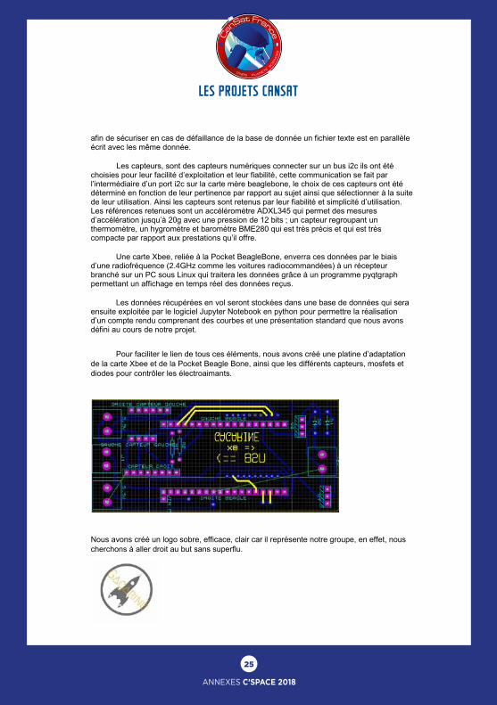
Pour faciliter le lien de tous ces éléments, nous avons créé une platine d’adaptation de la carte Xbee et de la Pocket Beagle Bone, ainsi que les différents capteurs, mosfets et diodes pour contrôler les électroaimants.
Nous avons créé un logo sobre, efficace, clair car il représente notre groupe, en effet, nous cherchons à aller droit au but sans superflu.
26
ANNEXES C’SPACE 2018
LES PROJETS CANSAT
Swarog II, a step further in CanSat probes
1/3
Swarog II, a step further in CanSat probes
BILLIAU Hadrien, RAMBAUD Mathias, REYNES Edwin, SCAVAZZIN Antoine, SESMA-RUSSO Pablo, THOMAS Anaïs
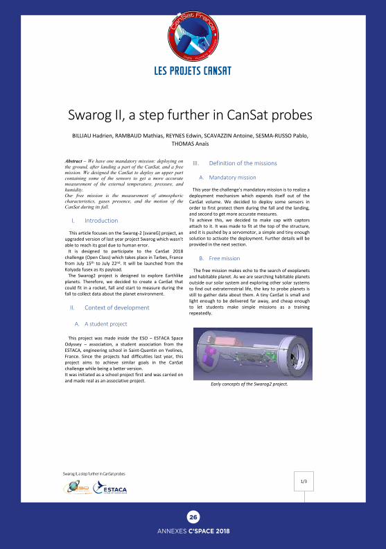
Abstract – We have one mandatory mission: deploying on the ground, after landing a part of the CanSat, and a free mission. We designed the CanSat to deploy an upper part containing some of the sensors to get a more accurate measurement of the external temperature, pressure, and humidity. Our free mission is the measurement of atmospheric characteristics, gases presence, and the motion of the CanSat during its fall.
I. Introduction This article focuses on the Swarog-2 [svarɞG] project, an upgraded version of last year project Swarog which wasn’t able to reach its goal due to human error. It is designed to participate to the CanSat 2018 challenge (Open Class) which takes place in Tarbes, France from July 15th to July 22nd. It will be launched from the Kolyada fusex as its payload. The Swarog2 project is designed to explore Earthlike planets. Therefore, we decided to create a CanSat that could fit in a rocket, fall and start to measure during the fall to collect data about the planet environment.
II. Context of development
A. A student project This project was made inside the ESO – ESTACA Space Odyssey – association, a student association from the ESTACA, engineering school in Saint-Quentin en Yvelines, France. Since the projects had difficulties last year, this project aims to achieve similar goals in the CanSat challenge while being a better version. It was initiated as a school project first and was carried on and made real as an associative project.
III. Definition of the missions
A. Mandatory mission This year the challenge’s mandatory mission is to realize a deployment mechanism which expends itself out of the CanSat volume. We decided to deploy some sensors in order to first protect them during the fall and the landing, and second to get more accurate measures. To achieve this, we decided to make cap with captors attach to it. It was made to fit at the top of the structure, and it is pushed by a servomotor, a simple and tiny enough solution to activate the deployment. Further details will be provided in the next section.
B. Free mission The free mission makes echo to the search of exoplanets and habitable planet. As we are searching habitable planets outside our solar system and exploring other solar systems to find out extraterrestrial life, the key to probe planets is still to gather data about them. A tiny CanSat is small and light enough to be delivered far away, and cheap enough to let students make simple missions as a training repeatedly.
Early concepts of the Swarog2 project.
Swarog II, a step further in CanSat probes
1/3
Swarog II, a step further in CanSat probes
BILLIAU Hadrien, RAMBAUD Mathias, REYNES Edwin, SCAVAZZIN Antoine, SESMA-RUSSO Pablo, THOMAS Anaïs
Abstract – We have one mandatory mission: deploying on the ground, after landing a part of the CanSat, and a free mission. We designed the CanSat to deploy an upper part containing some of the sensors to get a more accurate measurement of the external temperature, pressure, and humidity. Our free mission is the measurement of atmospheric characteristics, gases presence, and the motion of the CanSat during its fall.
I. Introduction This article focuses on the Swarog-2 [svarɞG] project, an upgraded version of last year project Swarog which wasn’t able to reach its goal due to human error. It is designed to participate to the CanSat 2018 challenge (Open Class) which takes place in Tarbes, France from July 15th to July 22nd. It will be launched from the Kolyada fusex as its payload. The Swarog2 project is designed to explore Earthlike planets. Therefore, we decided to create a CanSat that could fit in a rocket, fall and start to measure during the fall to collect data about the planet environment.
II. Context of development
A. A student project This project was made inside the ESO – ESTACA Space Odyssey – association, a student association from the ESTACA, engineering school in Saint-Quentin en Yvelines, France. Since the projects had difficulties last year, this project aims to achieve similar goals in the CanSat challenge while being a better version. It was initiated as a school project first and was carried on and made real as an associative project.
III. Definition of the missions
A. Mandatory mission This year the challenge’s mandatory mission is to realize a deployment mechanism which expends itself out of the CanSat volume. We decided to deploy some sensors in order to first protect them during the fall and the landing, and second to get more accurate measures. To achieve this, we decided to make cap with captors attach to it. It was made to fit at the top of the structure, and it is pushed by a servomotor, a simple and tiny enough solution to activate the deployment. Further details will be provided in the next section.
B. Free mission The free mission makes echo to the search of exoplanets and habitable planet. As we are searching habitable planets outside our solar system and exploring other solar systems to find out extraterrestrial life, the key to probe planets is still to gather data about them. A tiny CanSat is small and light enough to be delivered far away, and cheap enough to let students make simple missions as a training repeatedly.
Early concepts of the Swarog2 project.
27
ANNEXES C’SPACE 2018
LES PROJETS CANSAT LES PROJETS CANSAT
Swarog II, a step further in CanSat probes
2/3
IV. Technical solutions
A. Mandatory mission As for the mandatory mission, we use a servomotor controlled by a RaspberryPi Zero. The motor has a dedicated 9V battery to be autonomous on energy. The motor will pry open the cap and expose captors to the atmosphere at the end of a timer initiated by unplugging a jack connector during takeoff.
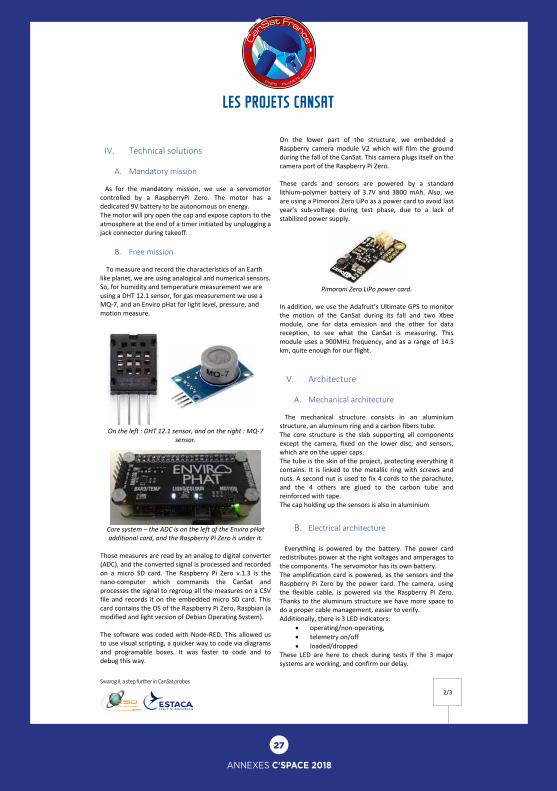
B. Free mission To measure and record the characteristics of an Earth like planet, we are using analogical and numerical sensors. So, for humidity and temperature measurement we are using a DHT 12.1 sensor, for gas measurement we use a MQ-7, and an Enviro pHat for light level, pressure, and motion measure.
On the left : DHT 12.1 sensor, and on the right : MQ-7 sensor.
Core system – the ADC is on the left of the Enviro pHat additional card, and the Raspberry Pi Zero is under it.
Those measures are read by an analog to digital converter (ADC), and the converted signal is processed and recorded on a micro SD card. The Raspberry Pi Zero v.1.3 is the nano-computer which commands the CanSat and processes the signal to regroup all the measures on a CSV file and records it on the embedded micro SD card. This card contains the OS of the Raspberry Pi Zero, Raspbian (a modified and light version of Debian Operating System). The software was coded with Node-RED. This allowed us to use visual scripting, a quicker way to code via diagrams and programable boxes. It was faster to code and to debug this way.
On the lower part of the structure, we embedded a Raspberry camera module V2 which will film the ground during the fall of the CanSat. This camera plugs itself on the camera port of the Raspberry Pi Zero. These cards and sensors are powered by a standard lithium-polymer battery of 3.7V and 3800 mAh. Also, we are using a Pimoroni Zero LiPo as a power card to avoid last year’s sub-voltage during test phase, due to a lack of stabilized power supply.
Pimoroni Zero LiPo power card. In addition, we use the Adafruit’s Ultimate GPS to monitor the motion of the CanSat during its fall and two Xbee module, one for data emission and the other for data reception, to see what the CanSat is measuring. This module uses a 900MHz frequency, and as a range of 14.5 km, quite enough for our flight.
V. Architecture
A. Mechanical architecture The mechanical structure consists in an aluminium structure, an aluminum ring and a carbon fibers tube. The core structure is the slab supporting all components except the camera, fixed on the lower disc, and sensors, which are on the upper caps. The tube is the skin of the project, protecting everything it contains. It is linked to the metallic ring with screws and nuts. A second nut is used to fix 4 cords to the parachute, and the 4 others are glued to the carbon tube and reinforced with tape. The cap holding up the sensors is also in aluminium
B. Electrical architecture Everything is powered by the battery. The power card redistributes power at the right voltages and amperages to the components. The servomotor has its own battery. The amplification card is powered, as the sensors and the Raspberry Pi Zero by the power card. The camera, using the flexible cable, is powered via the Raspberry Pi Zero. Thanks to the aluminum structure we have more space to do a proper cable management, easier to verify. Additionally, there is 3 LED indicators:
• operating/non-operating, • telemetry on/off • loaded/dropped
These LED are here to check during tests if the 3 major systems are working, and confirm our delay.
Swarog II, a step further in CanSat probes
2/3
IV. Technical solutions
A. Mandatory mission As for the mandatory mission, we use a servomotor controlled by a RaspberryPi Zero. The motor has a dedicated 9V battery to be autonomous on energy. The motor will pry open the cap and expose captors to the atmosphere at the end of a timer initiated by unplugging a jack connector during takeoff.
B. Free mission To measure and record the characteristics of an Earth like planet, we are using analogical and numerical sensors. So, for humidity and temperature measurement we are using a DHT 12.1 sensor, for gas measurement we use a MQ-7, and an Enviro pHat for light level, pressure, and motion measure.
On the left : DHT 12.1 sensor, and on the right : MQ-7 sensor.
Core system – the ADC is on the left of the Enviro pHat additional card, and the Raspberry Pi Zero is under it.
Those measures are read by an analog to digital converter (ADC), and the converted signal is processed and recorded on a micro SD card. The Raspberry Pi Zero v.1.3 is the nano-computer which commands the CanSat and processes the signal to regroup all the measures on a CSV file and records it on the embedded micro SD card. This card contains the OS of the Raspberry Pi Zero, Raspbian (a modified and light version of Debian Operating System). The software was coded with Node-RED. This allowed us to use visual scripting, a quicker way to code via diagrams and programable boxes. It was faster to code and to debug this way.
On the lower part of the structure, we embedded a Raspberry camera module V2 which will film the ground during the fall of the CanSat. This camera plugs itself on the camera port of the Raspberry Pi Zero. These cards and sensors are powered by a standard lithium-polymer battery of 3.7V and 3800 mAh. Also, we are using a Pimoroni Zero LiPo as a power card to avoid last year’s sub-voltage during test phase, due to a lack of stabilized power supply.
Pimoroni Zero LiPo power card. In addition, we use the Adafruit’s Ultimate GPS to monitor the motion of the CanSat during its fall and two Xbee module, one for data emission and the other for data reception, to see what the CanSat is measuring. This module uses a 900MHz frequency, and as a range of 14.5 km, quite enough for our flight.
V. Architecture
A. Mechanical architecture The mechanical structure consists in an aluminium structure, an aluminum ring and a carbon fibers tube. The core structure is the slab supporting all components except the camera, fixed on the lower disc, and sensors, which are on the upper caps. The tube is the skin of the project, protecting everything it contains. It is linked to the metallic ring with screws and nuts. A second nut is used to fix 4 cords to the parachute, and the 4 others are glued to the carbon tube and reinforced with tape. The cap holding up the sensors is also in aluminium
B. Electrical architecture Everything is powered by the battery. The power card redistributes power at the right voltages and amperages to the components. The servomotor has its own battery. The amplification card is powered, as the sensors and the Raspberry Pi Zero by the power card. The camera, using the flexible cable, is powered via the Raspberry Pi Zero. Thanks to the aluminum structure we have more space to do a proper cable management, easier to verify. Additionally, there is 3 LED indicators:
• operating/non-operating, • telemetry on/off • loaded/dropped
These LED are here to check during tests if the 3 major systems are working, and confirm our delay.
28
ANNEXES C’SPACE 2018
LES PROJETS CANSAT
LES POSTERS DES CLUBS
Swarog II, a step further in CanSat probes
3/3
A. Team organization Project leader: BILLIAU Hadrien Software team: REYNES Edwin Hardware team: RAMBAUD Mathias THOMAS Anaïs Mechanical team: SCAVAZZIN Antoine SESMA-RUSSO Pablo
VI. Conclusion The CanSat is still in progress, and the integration is on its way. The different elements are working fine, the final test will be done when the project will be assembled. We had some issue about parts shipping and aluminum parts machining. This project was a great opportunity to design and upgrade a previous project. This working prototype will be another concept to explore remotely other worlds, and we hope it will be a source of inspiration for other students or projects makers. And thanks to last year mistakes we are able to pursue this project to make it better, thus to learn the hard way how engineers works.
VII. Acknowledgement We would like to thank for their help and their participation Mr. Pierre-Emmanuel Mangin and FabLab ESTACA for the 3D printing technology and the advices