Embed Size (px)
Citation preview
Calculus and Structures 98
Calculus and Structures 99
CHAPTER 7 COMPUTATION OF SHEAR FORCE AND BENDING MOMENT FOR A CONCENTRATED LOAD
Calculus and Structures
Chapter 7 COMPUTATION OF SHEAR FORCE
100
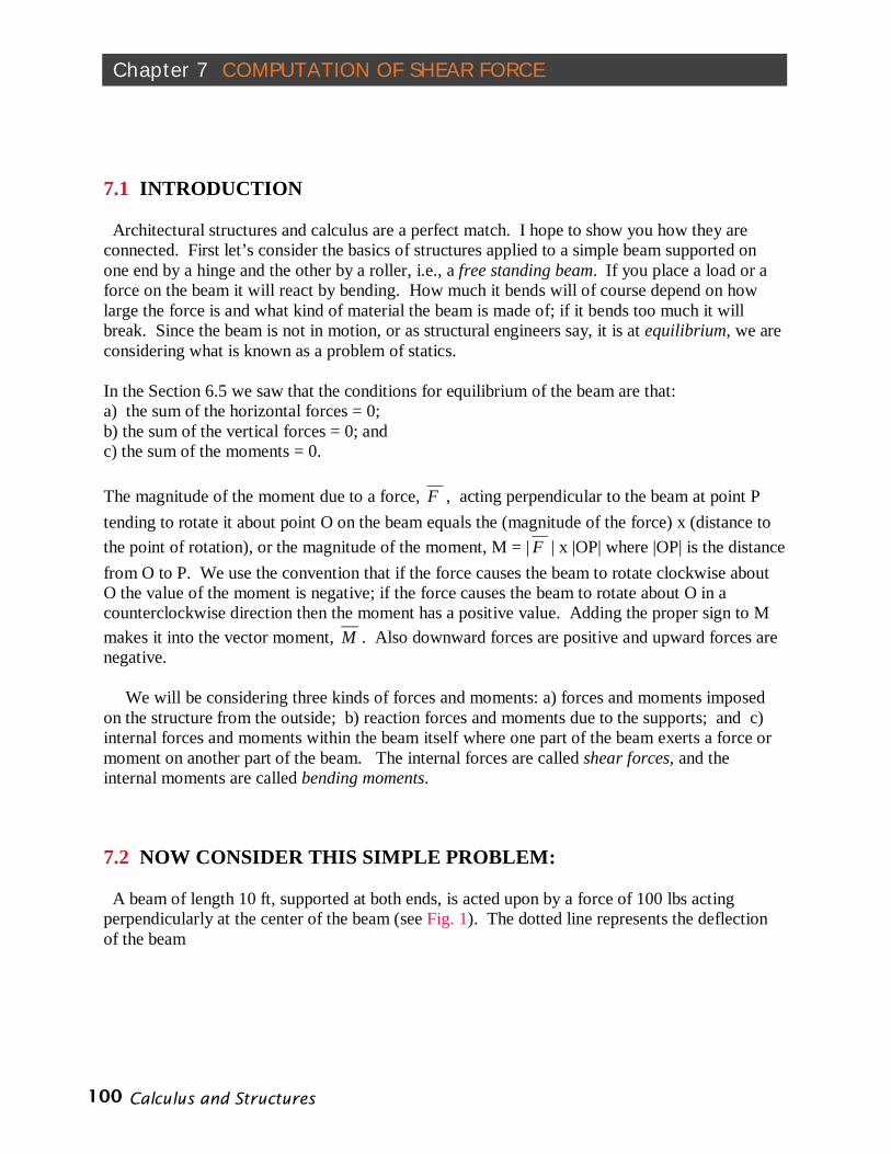
7.1 INTRODUCTION Architectural structures and calculus are a perfect match. I hope to show you how they are connected. First let’s consider the basics of structures applied to a simple beam supported on one end by a hinge and the other by a roller, i.e., a free standing beam. If you place a load or a force on the beam it will react by bending. How much it bends will of course depend on how large the force is and what kind of material the beam is made of; if it bends too much it will break. Since the beam is not in motion, or as structural engineers say, it is at equilibrium, we are considering what is known as a problem of statics. In the Section 6.5 we saw that the conditions for equilibrium of the beam are that: a) the sum of the horizontal forces = 0; b) the sum of the vertical forces = 0; and c) the sum of the moments = 0. The magnitude of the moment due to a force, F , acting perpendicular to the beam at point P tending to rotate it about point O on the beam equals the (magnitude of the force) x (distance to the point of rotation), or the magnitude of the moment, M = | F | x |OP| where |OP| is the distance from O to P. We use the convention that if the force causes the beam to rotate clockwise about O the value of the moment is negative; if the force causes the beam to rotate about O in a counterclockwise direction then the moment has a positive value. Adding the proper sign to M makes it into the vector moment, M . Also downward forces are positive and upward forces are negative. We will be considering three kinds of forces and moments: a) forces and moments imposed on the structure from the outside; b) reaction forces and moments due to the supports; and c) internal forces and moments within the beam itself where one part of the beam exerts a force or moment on another part of the beam. The internal forces are called shear forces, and the internal moments are called bending moments.
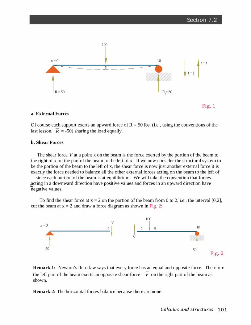
7.2 NOW CONSIDER THIS SIMPLE PROBLEM: A beam of length 10 ft, supported at both ends, is acted upon by a force of 100 lbs acting perpendicularly at the center of the beam (see Fig. 1). The dotted line represents the deflection of the beam
101Calculus and Structures
Section 7.2
Fig. 1
R = 50 R = 50
100
1 2
10
5
x = 0
( + )
( - )
100
Fig. 250 50
105x = 0
V
V
22
a. External Forces
Of course each support exerts an upward force of R = 50 lbs. (i.e., using the conventions of the last lesson, R = -50) sharing the load equally.
b. Shear Forces
The shear force V at a point x on the beam is the force exerted by the portion of the beam to the right of x on the part of the beam to the left of x. If we now consider the structural system to be the portion of the beam to the left of x, the shear force is now just another external force it is exactly the force needed to balance all the other external forces acting on the beam to the left of
x, since each portion of the beam is at equilibrium. We will take the convention that forces
acting in a downward direction have positive values and forces in an upward direction have negative values.
To find the shear force at x = 2 on the portion of the beam from 0 to 2, i.e., the interval [0,2], cut the beam at x = 2 and draw a force diagram as shown in Fig. 2:
Remark 1: Newton’s third law says that every force has an equal and opposite force. Therefore the left part of the beam exerts an opposite shear force –V on the right part of the beam as shown. Remark 2: The horizontal forces balance because there are none.
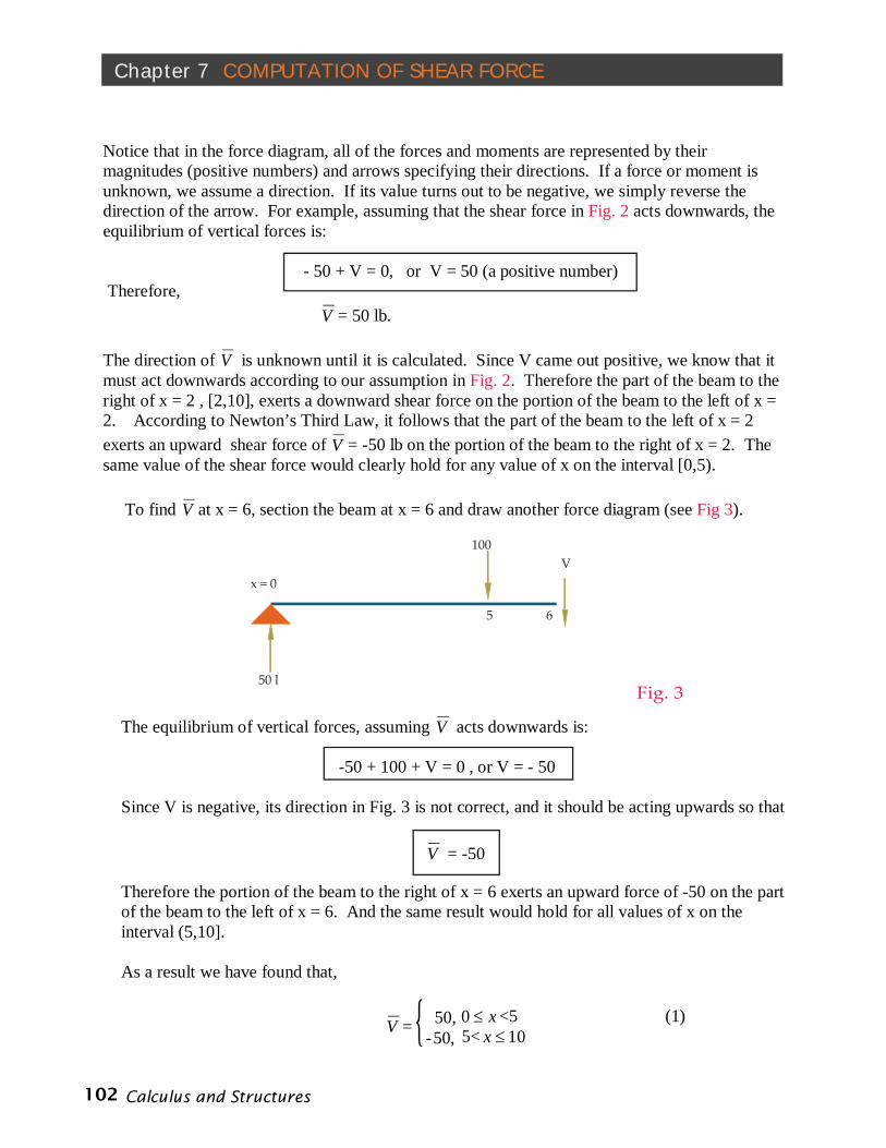
Fig. 3
Calculus and Structures 102
Chapter 7 COMPUTATION OF SHEAR FORCE
100
50 l
5
x = 0V
6
Notice that in the force diagram, all of the forces and moments are represented by their magnitudes (positive numbers) and arrows specifying their directions. If a force or moment is unknown, we assume a direction. If its value turns out to be negative, we simply reverse the direction of the arrow. For example, assuming that the shear force in Fig. 2 acts downwards, the equilibrium of vertical forces is: - 50 + V = 0, or V = 50 (a positive number) Therefore, V = 50 lb. The direction of V is unknown until it is calculated. Since V came out positive, we know that it must act downwards according to our assumption in Fig. 2. Therefore the part of the beam to the right of x = 2 , [2,10], exerts a downward shear force on the portion of the beam to the left of x = 2. According to Newton’s Third Law, it follows that the part of the beam to the left of x = 2 exerts an upward shear force of V = -50 lb on the portion of the beam to the right of x = 2. The same value of the shear force would clearly hold for any value of x on the interval [0,5). To find V at x = 6, section the beam at x = 6 and draw another force diagram (see Fig 3).
The equilibrium of vertical forces, assuming V acts downwards is:
-50 + 100 + V = 0 , or V = - 50 Since V is negative, its direction in Fig. 3 is not correct, and it should be acting upwards so that
V = -50 Therefore the portion of the beam to the right of x = 6 exerts an upward force of -50 on the part of the beam to the left of x = 6. And the same result would hold for all values of x on the interval (5,10]. As a result we have found that,
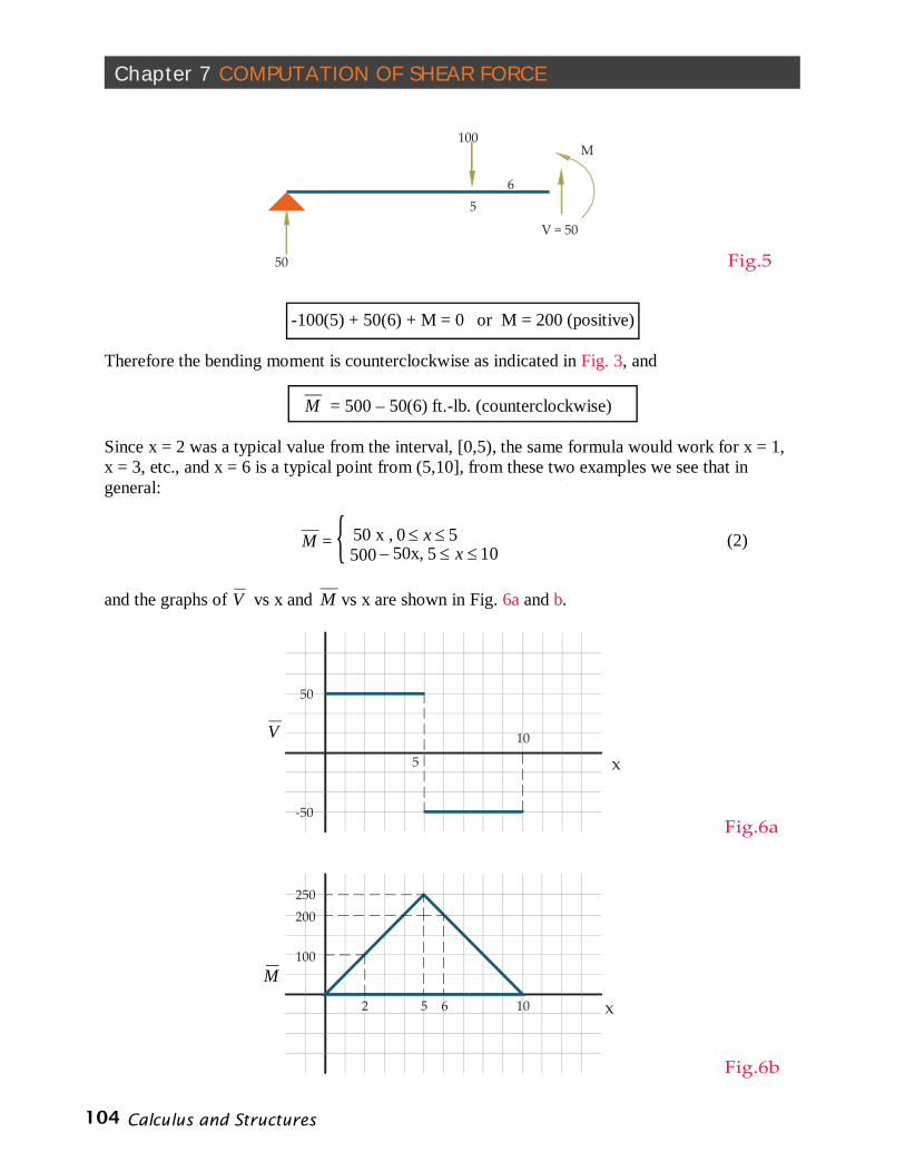
V = 50, x0 <5 (1) -50, 5< 10x {
103Calculus and Structures
Section 7.2
100
50
2x = 0
V = 50
M M
50
50
10
Fig.4
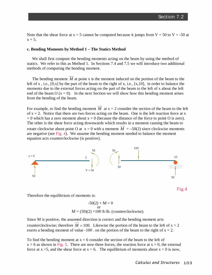
Note that the shear force at x = 5 cannot be computed because it jumps from V = 50 to V = -50 at x = 5. c. Bending Moments by Method 1 – The Statics Method We shall first compute the bending moments acting on the beam by using the method of statics. We refer to this as Method 1. In Sections 7.4 and 7.5 we will introduce two additional methods of computing the bending moment. The bending moment M at point x is the moment induced on the portion of the beam to the left of x , i.e., [0,x] by the part of the beam to the right of x, i.e., [x,10], in order to balance the moments due to the external forces acting on the part of the beam to the left of x about the left end of the beam O (x = 0). In the next Section we will show how this bending moment arises from the bending of the beam. For example, to find the bending moment M at x = 2 consider the section of the beam to the left of x = 2. Notice that there are two forces acting on the beam. One is the left reaction force at x = 0 which has a zero moment about x = 0 (because the distance of the force to point O is zero). The other is the shear force acting downwards which results in a moment causing the beam to rotate clockwise about point O at x = 0 with a moment M = –50(2) since clockwise moments are negative (see Fig. 4). We assume the bending moment needed to balance the moment equation acts counterclockwise (is positive).
Therefore the equilibrium of moments is:
or -50(2) + M = 0
M = (50)(2) =100 ft-lb. (counterclockwise). Since M is positive, the assumed direction is correct and the bending moment acts counterclockwise; therefore .100M Likewise the portion of the beam to the left of x = 2 exerts a bending moment of value -100 . on the portion of the beam to the right of x = 2. To find the bending moment at x = 6 consider the section of the beam to the left of x = 6 as shown in Fig. 5. There are now three forces, the reaction force at x = 0, the external force at x =5, and the shear force at x = 6. The equilibrium of moments about x = 0 is now,
Calculus and Structures 104
Chapter 7 COMPUTATION OF SHEAR FORCE
50
6
V = 50
M
Fig.5
5
100
V
50
-50
10
5 x
x2 5 6
100
10
200250
M
Fig.6a
Fig.6b
-100(5) + 50(6) + M = 0 or M = 200 (positive) Therefore the bending moment is counterclockwise as indicated in Fig. 3, and
M = 500 – 50(6) ft.-lb. (counterclockwise) Since x = 2 was a typical value from the interval, [0,5), the same formula would work for x = 1, x = 3, etc., and x = 6 is a typical point from (5,10], from these two examples we see that in general:
M = 50 x , 50 x (2) 500 – 50x, 105 x
and the graphs of V vs x and M vs x are shown in Fig. 6a and b.
{

105Calculus and Structures
Section 7.2
V = 50
8
V = 50
M = 100
Fig.7
5
100M = 150
3
d. Check on the Calculations Every portion of the beam is at equilibrium. Therefore as a check on the calculations, we can compute the balance of forces and moments on the portion of the beam from x = 3 to x = 8 shown in Fig. 7. If all is well, the sum of the forces and moments should add to zero.
From Eq.1, 50)3( V and 50)8( V , while from Eq. 2, 150)3( M and 100)8( M . Notice that at x = 3 the shear force acts upwards while the bending moment is clockwise because the forces are due to the part of the beam on the interval [0,3] acting on the portion of the beam on the interval [3,8]. By Newton’s third Law this force and moment are 50)3( V and
150)3( M . As a result the balance of forces are, 100 – 50 -50 = 0 And the balance of moments is, -150 – (100)(2) + (50)(5) + 100 = 0 So everything checks.

Calculus and Structures 106
Chapter 7 COMPUTATION OF SHEAR FORCE
7.3 SOME OBSERVATIONS Remark 3: The bending moment at x = 0 for a free standing beam is zero since there is no left side of the beam acting on the right side. At x = 10, the other end of the beam the bending moment is also zero because there is no right side of the beam to act on the left side. In general the bending moments at the ends of a free standing beam is .0M This can be used to check your computations. If the value of the moments are not zero at the ends then there is a mistake somewhere in the calculations. Remark 4: While the shear force jumps or is discontinuous at x = 5, the bending moment is continuous across the entire beam. The decrease in the shear force, V , from one side of the concentrated load to the other equals the force, i.e., FV ., i.e., the shear force jumps from 50 to the left of 100F to -50 on the other side of the force. Remark 5: Notice if you consider two points x1 and x2 along the beam, then the value of M 2 – M 1 is the signed area under the V vs x curve between x2 and x1 where the area is
considered to be negative if it is below the x-axis, i.e., dxVxMxMx
x
2
1
)()( 112 . For example if
you take x1 and x2 to be placed symmetrically around x = 5, since the signed area equals 0 it follows that M 2 = M 1 which is correct as you can see from Fig. 6b. Also since the moments at the beginning and end of a free standing beam are both zero, the total area under the shear force curve must be zero for a free standing beam which you can easily calculate from Fig. 6a. This is an excellent check on the correctness of your work. Remark 6: Notice that the slope of the M vs x curve at any value of x equals the value of V at that value of x. Remark 7: Notice that the maximum of the bending moment curve occurs at the point at which the shear force curve goes from a positive value to a negative value. Minimum values occur where the shear force goes from negative to positive. This will always be true. Remark 8: Notice that the M vs x curve is the approximate mirror reflection of the deflection of the beam. Where the bending moment rises the deflection curve falls and vice versa. Where the bending moment has a max or min the deflection has a min or max (see the dotted line in Fig. 1). Also where the bending moment is positive, the beam will bend concave upwards. We will see that when the bending moment is negative the beam bends concave downwards. This will always be true and can be used as another check on your work. Remark 9: The average value of the shear force over the length, L, of the beam introduced in
Chapter 3, dxVL
VL
avg 0
1 , equals 0 since by Remarks 3 and 5, 0)0()(
LMLMV avg for a
free standing beam.
107Calculus and Structures
Section 7.3
What I mean by solving a structures problem for a beam is to compute the shear stress and bending moment within the beam given a set of external forces at equilibrium imposed on the beam. As the result of the previous Remarks, there are three ways to solve for the bending moment:
1) Statics Method: Use the principals of statics, i.e., the sum of the horizontal, vertical forces on any section of the beam must sum to 0, and the sum of the moments about any point on the beam must sum to 0.
2) Area Method: Use the fact that: (the signed area under the V curve between x1 and x2 ) = M 2 - M 1. So if you know the bending moment M 1 at any point, say x1, you can use it find M2.at x2.
3) Slope Method: M at any point equals the value of a function that has a slope equal to V at the same point while also equaling zero when x = 0..
We used method 1 to solve the structures problem. Now let’s use method 2.
7.4 METHOD 2 – AREA METHOD First compute the shear force. Recall from Eq. 1 that, V =
50, x0 <5 -50, 5< 10x
Next, divide the beam into two regions, I : [0,5) and II: (5,10] ,
I II 0________________5___________________10
Let x be an arbitrary value in [0,5). The signed area under the V vs x curve is 50x, the area of a rectangle (see Fig. 6a). Therefore, M (x) – M (0) = 50x. But since M (0) = 0, M (x) = 50x , x0 < 5 Next let x be an arbitrary value in Region II. The signed area will be equal to 250 – 50(x – 5). Therefore,
{
Calculus and Structures 108
Chapter 7 COMPUTATION OF SHEAR FORCE
M (x) – M (0) = 250 – 50(x – 5). But since again M (0) = 0,
M (x) = 250 – 50(x – 5)
M (x) = 500 – 50x, 5< 10x This is the same value of M that we arrived at in Eq. 2 by using method 1. Now let’s consider method 3. 7.5 METHOD 3 – SLOPE METHOD What function has V for a slope? In our example the slope in Region I from x = 0 to x = 5 was 50. What function has that slope? Obviously the function is linear. But there are many lines with slope 50. However, they all have the form
M = 50x + b.
If you know the moment at any value of x, such as the endpoint, then you can use that to find b. Since the beam is free standing, M = 0 when x = 0 so,
0 = 50(0) + b or b = 0. Therefore, M = 50x, 50 x . (3)
Now consider x in Region II between x=5 and x=10. The slope is V = -50 so now, M = -50x + b (4)
Since M is a continuous function, compute M (5) using Eq. 3, i.e., M (5) = 50(5) = 250. Replace this in Eq. 4 to get , 250 = -50(5) + b or b = 500 Therefore, M = -50x + 500, 105 x
or

109Calculus and Structures
Section 7.5
C
TO
{
d
Fig.8
Again, we get the same answer as in Eq. 2 but by an entirely different method.
As a check, M =0 at x = 10 since the beam is free-standing.
Extra Bonus: Once you solve the structures problem by method 3 you get the added bonus of getting the answer to method 2. In other words by plugging in x1 and x2 into M (x) derived by the slope method, you get the signed area under the V(x) curve from x1 to x2 from method 2, i.e., Signed Area = M (x2) - M (x1). So you can use the information about slopes to find signed areas without having to do the laborious job of adding rectangles. We shall develop this idea further in succeeding chapters.
7.6 WHERE DOES THE BENDING MOMENT COME FROM?
When a beam bends, half of the beam is under compression while the other half is under tension. You can easily see this by bending a sponge. In Fig. 8, as a result of the bending, the upper half of the sponge is under compression while the lower half experiences tension. The plane through the center of the beam, called the neutral plane, has no stress upon it. Take a section of the beam at an arbitrary point and look at the net compressive force C and net tensile force T acting on the left portion of the beam due to the action of the right side of the beam, where T = C as required by the equilibrium of horizontal forces. Fig. 8 shows the sponge bent concave up. This has a positive bending moment, i.e., counterclockwise.
Calculus and Structures 110
Chapter 7 COMPUTATION OF SHEAR FORCE
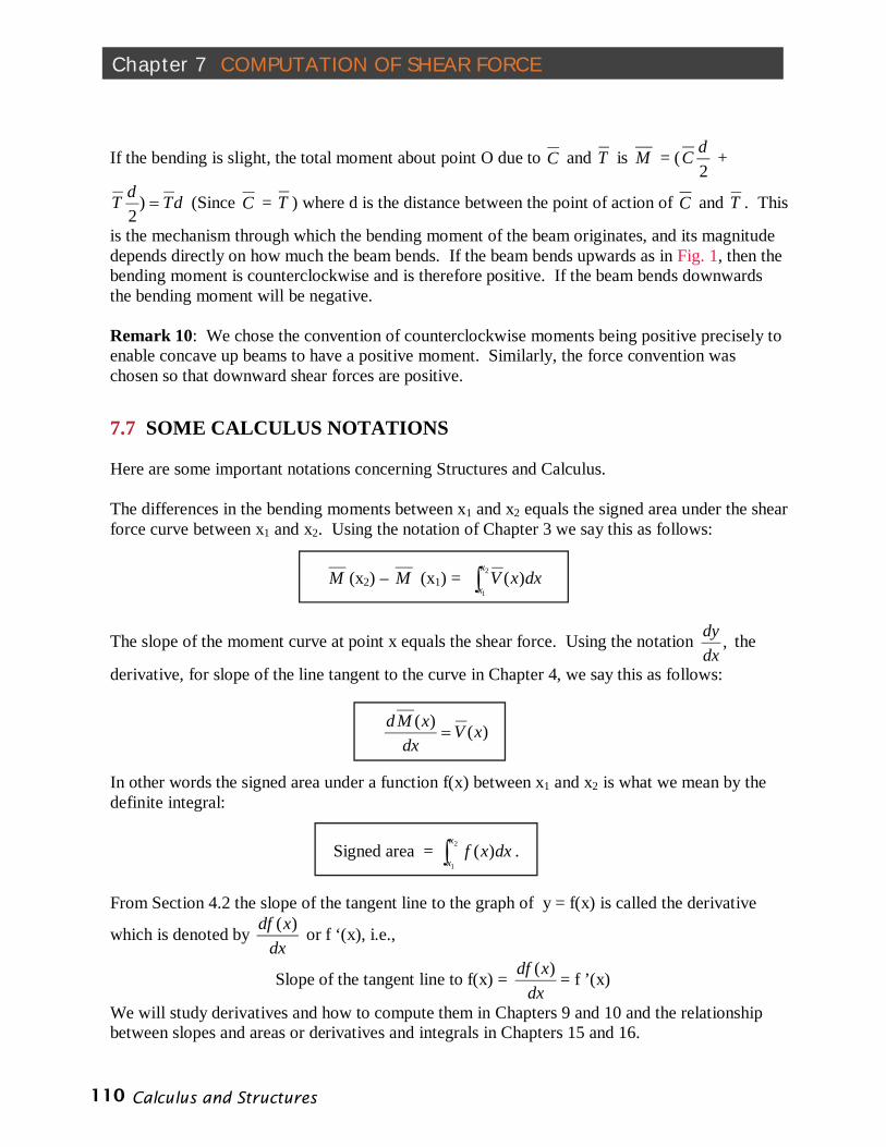
If the bending is slight, the total moment about point O due to C and T is M = (2dC +
dTdT )2
(Since C = T ) where d is the distance between the point of action of C and T . This
is the mechanism through which the bending moment of the beam originates, and its magnitude depends directly on how much the beam bends. If the beam bends upwards as in Fig. 1, then the bending moment is counterclockwise and is therefore positive. If the beam bends downwards the bending moment will be negative. Remark 10: We chose the convention of counterclockwise moments being positive precisely to enable concave up beams to have a positive moment. Similarly, the force convention was chosen so that downward shear forces are positive.
7.7 SOME CALCULUS NOTATIONS Here are some important notations concerning Structures and Calculus. The differences in the bending moments between x1 and x2 equals the signed area under the shear force curve between x1 and x2. Using the notation of Chapter 3 we say this as follows:
M (x2) – M (x1) = 2
1
)(x
xdxxV
The slope of the moment curve at point x equals the shear force. Using the notation ,dxdy the
derivative, for slope of the line tangent to the curve in Chapter 4, we say this as follows:
)()( xVdx
xMd
In other words the signed area under a function f(x) between x1 and x2 is what we mean by the definite integral:
Signed area = 2
1
)(x
xdxxf .
From Section 4.2 the slope of the tangent line to the graph of y = f(x) is called the derivative
which is denoted by dx
xdf )( or f ‘(x), i.e.,
Slope of the tangent line to f(x) = dx
xdf )( = f ’(x)
We will study derivatives and how to compute them in Chapters 9 and 10 and the relationship between slopes and areas or derivatives and integrals in Chapters 15 and 16.
111Calculus and Structures
Section 7.8
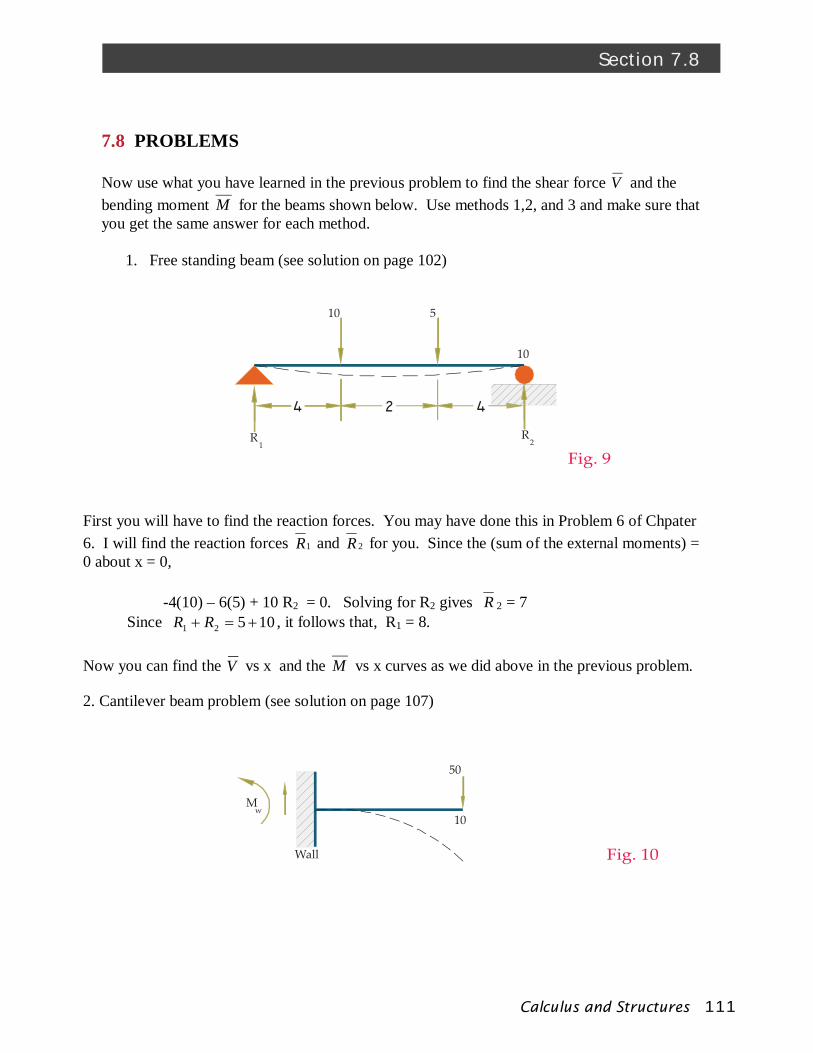
Fig. 9R R
10
1 2
10
5
Fig. 10
M
50
w10
Wall
7.8 PROBLEMS Now use what you have learned in the previous problem to find the shear force V and the bending moment M for the beams shown below. Use methods 1,2, and 3 and make sure that you get the same answer for each method.
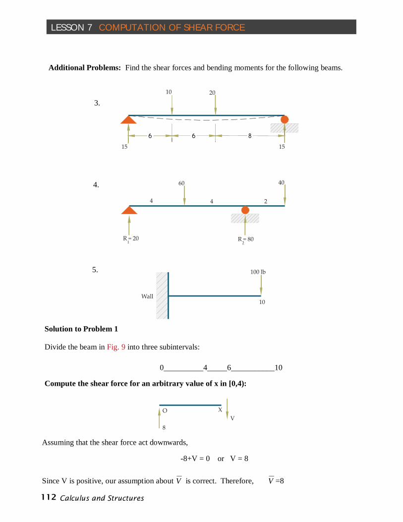
1. Free standing beam (see solution on page 102)
First you will have to find the reaction forces. You may have done this in Problem 6 of Chpater 6. I will find the reaction forces 1R and 2R for you. Since the (sum of the external moments) = 0 about x = 0, -4(10) – 6(5) + 10 R2 = 0. Solving for R2 gives R 2 = 7 Since 10521 RR , it follows that, R1 = 8. Now you can find the V vs x and the M vs x curves as we did above in the previous problem. 2. Cantilever beam problem (see solution on page 107)
Calculus and Structures 112
LESSON 7 COMPUTATION OF SHEAR FORCE
10 20
15 15
60
4 4 2
40
R = 20 1 R = 80
2
100 lb
10Wall
8V
O X
3.
4.
5.
Additional Problems: Find the shear forces and bending moments for the following beams.
Solution to Problem 1 Divide the beam in Fig. 9 into three subintervals:
0__________4_____6___________10 Compute the shear force for an arbitrary value of x in [0,4):
Assuming that the shear force act downwards, -8+V = 0 or V = 8 Since V is positive, our assumption about V is correct. Therefore, V =8
113Calculus and Structures
Section 7.8
8
V
10
8
V
10 5
O 4 6
x
x
4
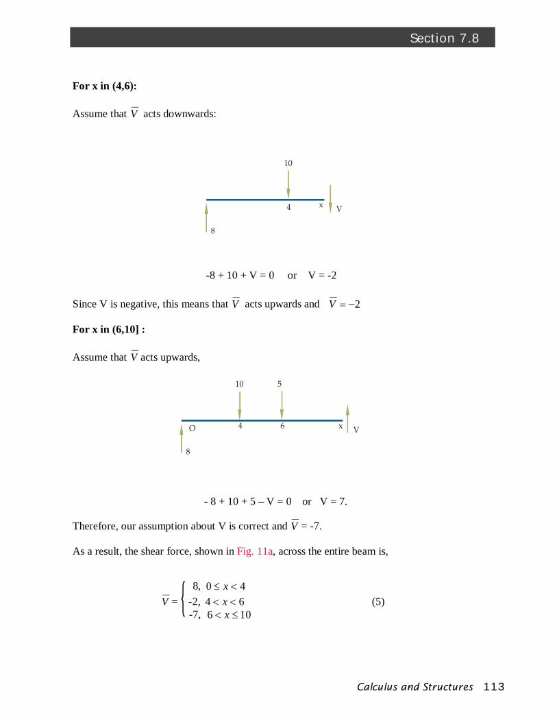
For x in (4,6): Assume that V acts downwards:
-8 + 10 + V = 0 or V = -2 Since V is negative, this means that V acts upwards and 2V For x in (6,10] : Assume that V acts upwards,
- 8 + 10 + 5 – V = 0 or V = 7. Therefore, our assumption about V is correct and V = -7. As a result, the shear force, shown in Fig. 11a, across the entire beam is,
8, 40 x V = -2, 64 x (5)
-7, 106 x {
Calculus and Structures 114
Chapter 7 COMPUTATION OF SHEAR FORCE
8
x
V = 8
M
o
4
10
8 V = 2
M
o
4
10
8 V = 7
M
o 6
5
x
We can also compute V by a shortcut method. First we compute V in interval [0,4) to get 8V . Then we observed in Remark 4 that the decrease in the shear force equals the external
force, i.e., FV . Since F = 10 at x = 4, it follows that in interval (4,6), V = -2. Similarly, since F = 5 at x = 6, in interval (6,10], V = - 7. Check: The area under the V vs x curve is : 32 - 4 – 28 = 0 Compute M by Method 1 (the Statics Method): For x in interval, [0,4):
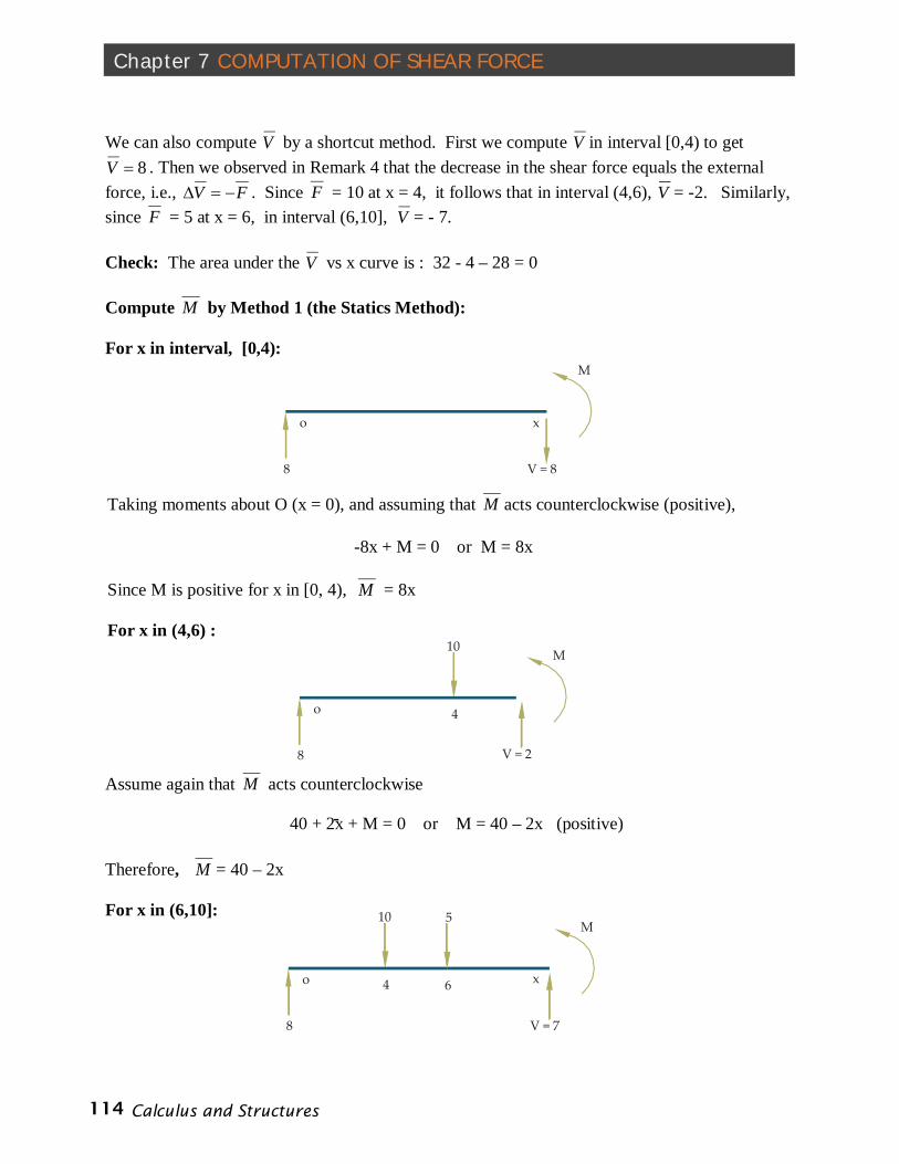
Taking moments about O (x = 0), and assuming that M acts counterclockwise (positive),
-8x + M = 0 or M = 8x Since M is positive for x in [0, 4), M = 8x For x in (4,6) :
Assume again that M acts counterclockwise
-40 + 2x + M = 0 or M = 40 – 2x (positive)
Therefore, M = 40 – 2x For x in (6,10]:
115Calculus and Structures
Section 7.8
x1064
8
-2
-7
V
M
1064 x
Fig. 11bFig. 11a
-40 – 30 +7x + M = 0 or M = 70 – 7x
Therefore, M = 70- 7x Check: M = 0 when x = 10
8x 40 x M = 40 – 2x 64 x (6) 70 – 7x 10⁶ x
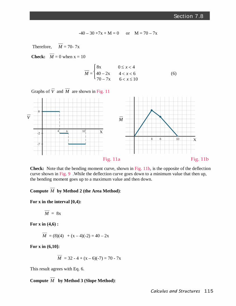
Graphs of V and M are shown in Fig. 11
{
Check: Note that the bending moment curve, shown in Fig. 11b, is the opposite of the deflection curve shown in Fig. 9 .While the deflection curve goes down to a minimum value that then up, the bending moment goes up to a maximum value and then down. Compute M by Method 2 (the Area Method): For x in the interval [0,4): M = 8x For x in (4,6) : M = (8)(4) + (x – 4)(-2) = 40 – 2x For x in (6,10]:
M = 32 - 4 + (x – 6)(-7) = 70 - 7x This result agrees with Eq. 6. Compute M by Method 3 (Slope Method):
Calculus and Structures 116
Chapter 7 COMPUTATION OF SHEAR FORCE
For x in interval, [0,4):
Since the slope of the M curve equals the value of the V curve, i.e., slope = 8, M = 8x
Since M = 0 when x = 0: 0 = (8)(0) + b or b = 0 Therefore, M = 8x (7) For x in (4,6) Since ,2V M = - 2x + b From Eq. 7, M = 32 when x = 4, and since M is continuous, 32 = - 2(4) + b or b = 40 Therefore, M = - 2x + 40 (8) For x in (6,10]: Since ,7V M = -7 x + b From Eq. 8, M = 28 when x = 6. Therefore, 28 = -7(6) + b or b = 70 and, M = -7 x + 70 This result agrees with Eq. 6 As a check, M = 0 when x = 10.
117Calculus and Structures
Section 7.8
4
10
V = 8 V = 7
M = 14
3 6
5
8
Fig.12
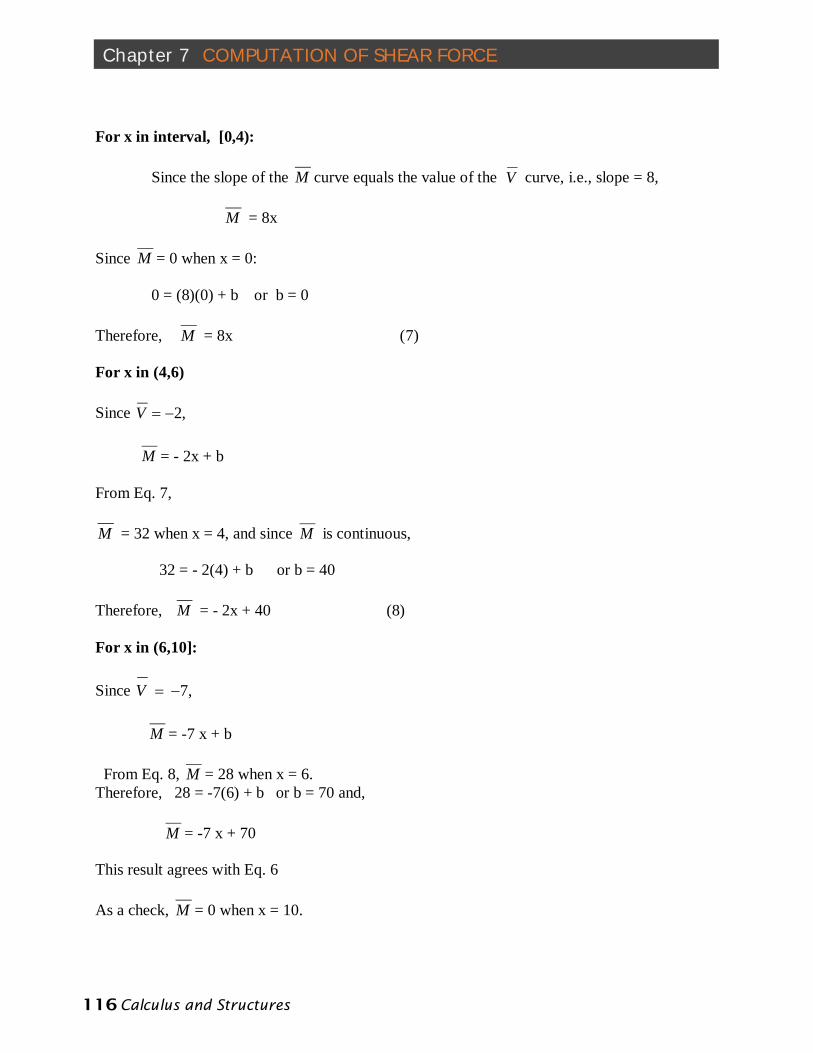
M = 24
As a final check on this evaluation of shear force and bending moment we consider the portion of the beam on the interval [3,8] (see Fig. 12) and show that the forces and moments balance on this portion of the beam.
Balance of forces: Since V =8 when x = 3, by Newton’s third law, the beam to the left of x = 3 acts on the portion to the right of x=3 so that V = - 8. On the other hand, from Eq. 5, at x = 8, V = - 7 . Therefore,
- 8 + 10 + 5 – 7 = 0 Balance of Moments: Taking the moments about x = 3 (point O),
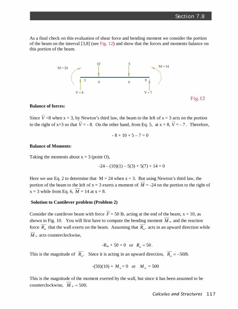
-24 – (10)(1) – 5(3) + 5(7) + 14 = 0 Here we use Eq. 2 to determine that M = 24 when x = 3. But using Newton’s third law, the portion of the beam to the left of x = 3 exerts a moment of M = -24 on the portion to the right of x = 3 while from Eq. 6, M = 14 at x = 8. Solution to Cantilever problem (Problem 2) Consider the cantilever beam with force F = 50 lb. acting at the end of the beam, x = 10, as shown in Fig. 10. You will first have to compute the bending moment wM and the reaction force wR that the wall exerts on the beam. Assuming that .wR acts in an upward direction while
wM acts counterclockwise, -Rw + 50 = 0 or 50wR .
This is the magnitude of .wR Since it is acting in an upward direction, .50lbRw
-(50)(10) + wM = 0 or wM = 500 This is the magnitude of the moment exerted by the wall, but since it has been assumed to be counterclockwise, .500wM
Calculus and Structures 118
Chapter 7 COMPUTATION OF SHEAR FORCE
V
10 x
Fig. 14a
50
V
Wall x M M = 500w
R = 50w
Fig. 13
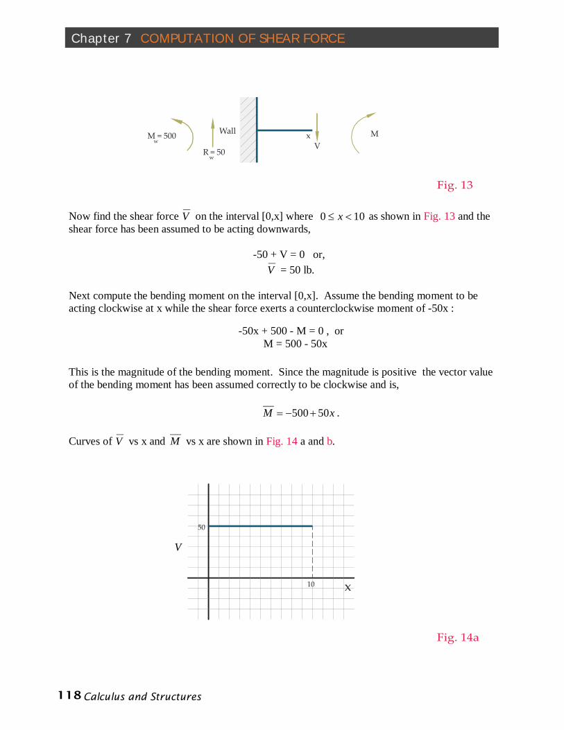
Now find the shear force V on the interval [0,x] where 100 x as shown in Fig. 13 and the shear force has been assumed to be acting downwards,
-50 + V = 0 or, V = 50 lb.
Next compute the bending moment on the interval [0,x]. Assume the bending moment to be acting clockwise at x while the shear force exerts a counterclockwise moment of -50x :
-50x + 500 - M = 0 , or M = 500 - 50x
This is the magnitude of the bending moment. Since the magnitude is positive the vector value of the bending moment has been assumed correctly to be clockwise and is,
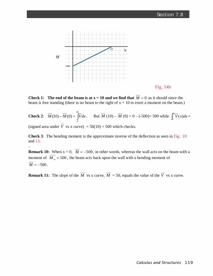
xM 50500 . Curves of V vs x and M vs x are shown in Fig. 14 a and b.
119Calculus and Structures
Section 7.8
x10
-500
M
Fig. 14b
Check 1: The end of the beam is at x = 10 and we find that 0M as it should since the beam is free standing (there is no beam to the right of x = 10 to exert a moment on the beam.)
Check 2: dxVMM 10
0
)0()10( . But M (10) – M (0) = 0 – (-500)= 500 while 10
0)( dxxV =
(signed area under V vs x curve) = 50(10) = 500 which checks. Check 3: The bending moment is the approximate inverse of the deflection as seen in Fig. 10 and 13. . Remark 10: When x = 0, 500M , in other words, whereas the wall acts on the beam with a moment of 500wM , the beam acts back upon the wall with a bending moment of
500M . Remark 11: The slope of the M vs x curve, M = 50, equals the value of the V vs x curve.