Embed Size (px)
Citation preview
PARAMETRIC MODELING WITH SOLID
WORKSLesson 1
Introduction
Introduction
Workbook- Use it like one (You are not going to sell this book back)
Use Questions and Exercises at end of each chapter to solidify your understanding
Employers look at software capabilities highly
Solid Works Certifications Certified Solid Works Associate (CSWA) http://www.solidworks.com/sw/support/796_ENU_HTML.htm
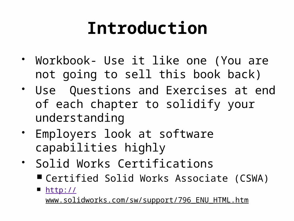
Computer Aided Engineering
Create it like a machinist Create Whole Remove parts and pieces Assemble together pieces like welder
http://www.solidengineering.co.nz/gallery_portfolio.htm
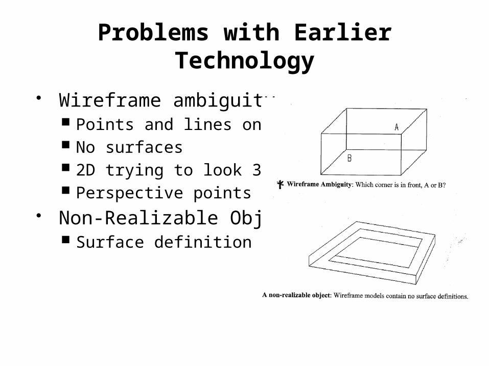
Problems with Earlier Technology
Wireframe ambiguity Points and lines only No surfaces 2D trying to look 3D Perspective points
Non-Realizable Object Surface definition
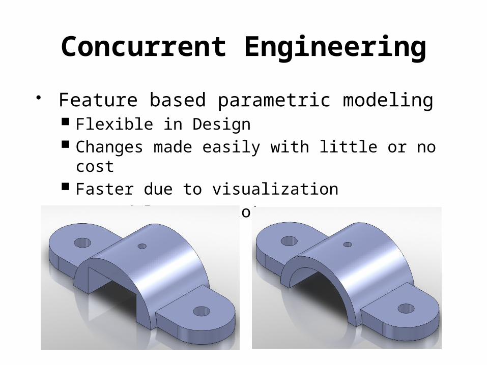
Concurrent Engineering
Feature based parametric modeling Flexible in Design Changes made easily with little or no cost Faster due to visualization No models or prototypes necessary
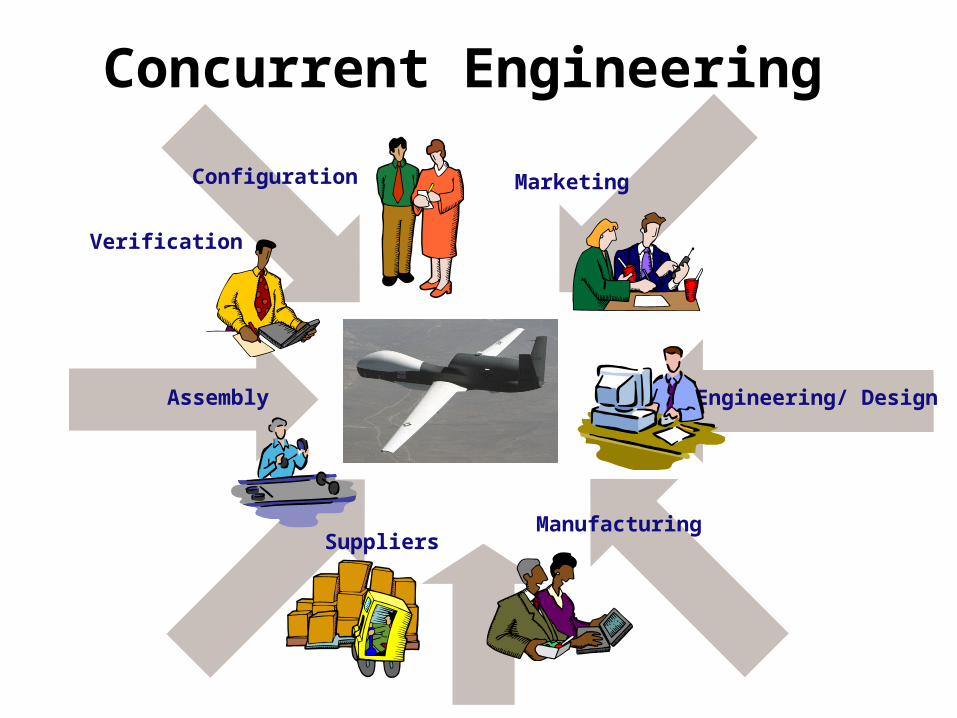
Concurrent Engineering
Manufacturing
Engineering/ Design
Marketing
Suppliers
Assembly
Verification
Configuration
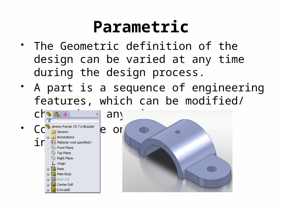
Parametric The Geometric definition of the design
can be varied at any time during the design process.
A part is a sequence of engineering features, which can be modified/ changed at any time.
Concentrate on original design intent

Parametric Modeling Benefits Begin with simple conceptual models with minimal detail “shape before
size” Geometric relations, dimensional constraints, and relational parametric
equations can be used to capture design intent Ability to update entire system, including parts, assemblies, and
drawings after changing one parameter in one place Quickly explore and evaluate different design variations and alternatives
to determine best design. Existing data can be used to create new designs Quick design turn around.
2 types of constraints: _____________________ _____________________
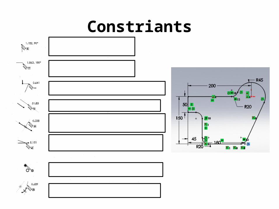
Constriants

Starting Solid Works Menu Bar Resources Icon- task pane, design library, file explorer Start up Options- if not there click on resources icon Task Pane- to close click in main area Option to pin open with pin in upper corner Tutorials
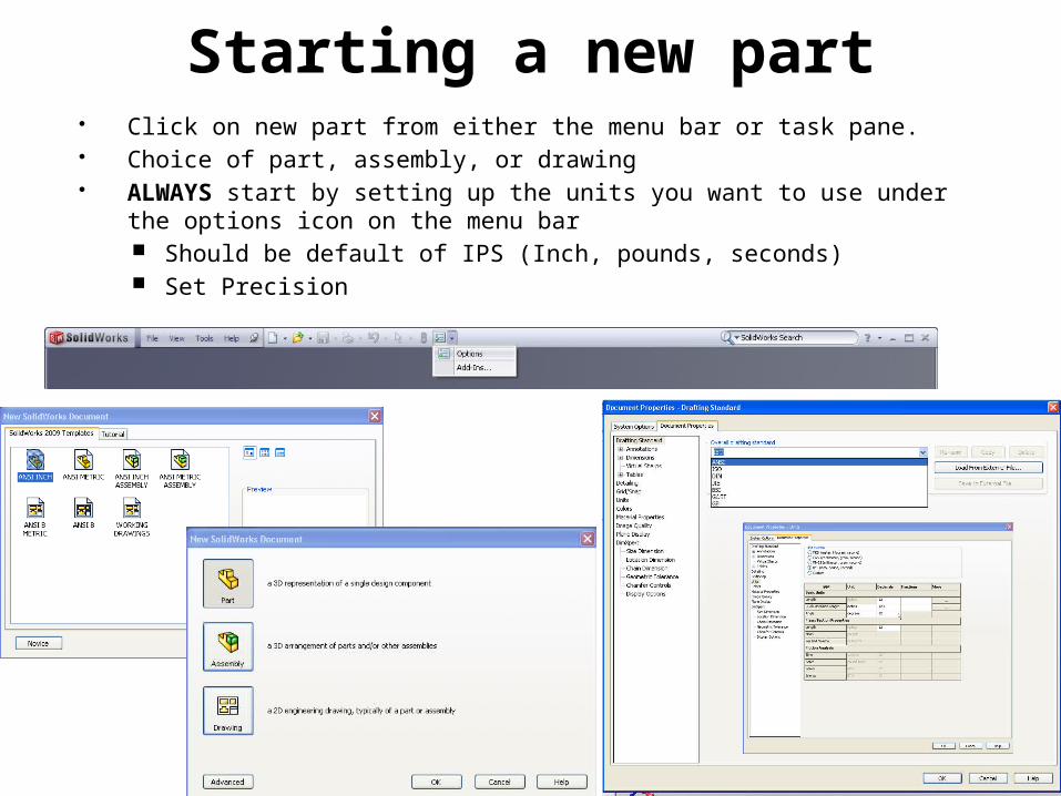
Starting a new part Click on new part from either the menu bar or task pane. Choice of part, assembly, or drawing ALWAYS start by setting up the units you want to use under the options
icon on the menu bar Should be default of IPS (Inch, pounds, seconds) Set Precision
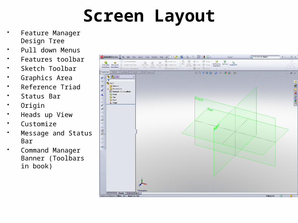
Screen Layout Feature Manager
Design Tree Pull down Menus Features toolbar Sketch Toolbar Graphics Area Reference Triad Status Bar Origin Heads up View Customize Message and Status
Bar Command Manager
Banner (Toolbars in book)
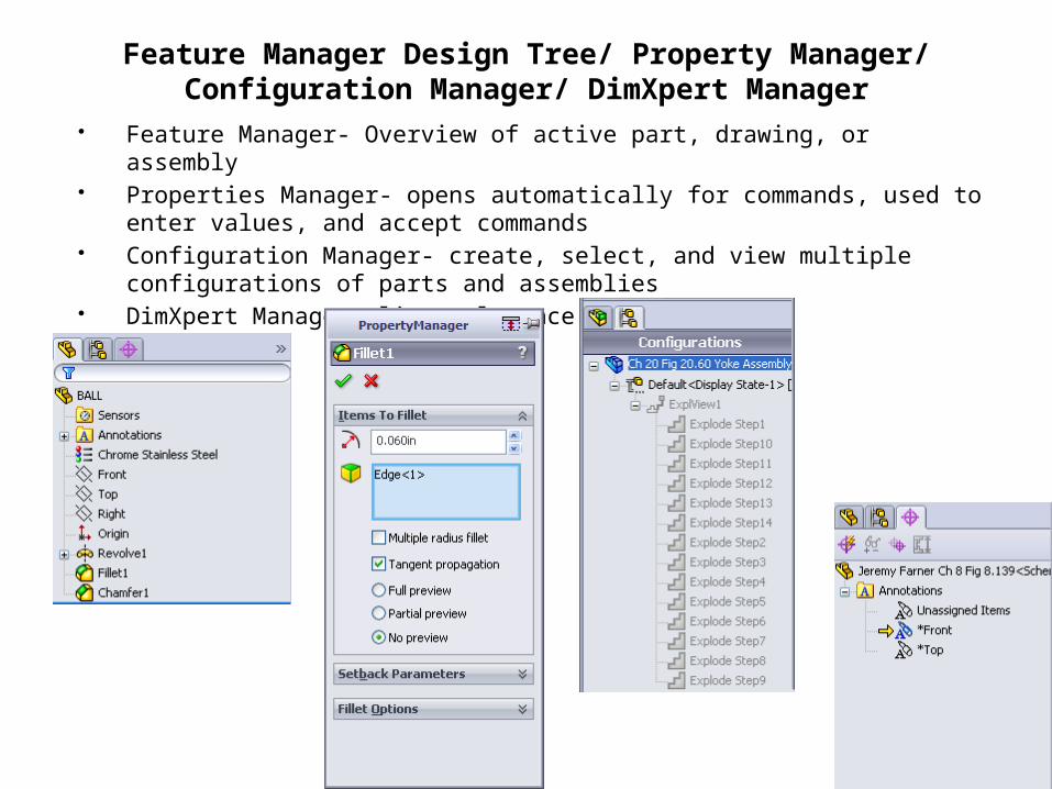
Feature Manager Design Tree/ Property Manager/ Configuration Manager/ DimXpert Manager
Feature Manager- Overview of active part, drawing, or assembly Properties Manager- opens automatically for commands, used to enter
values, and accept commands Configuration Manager- create, select, and view multiple configurations
of parts and assemblies DimXpert Manager- list tolerance features
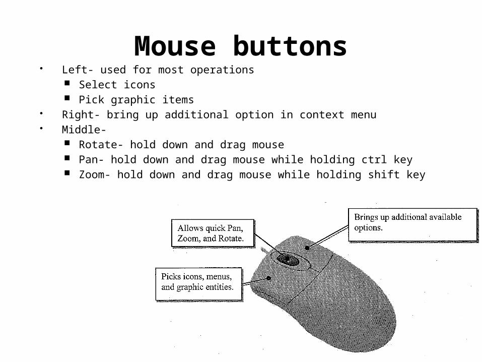
Mouse buttons Left- used for most operations
Select icons Pick graphic items
Right- bring up additional option in context menu Middle-
Rotate- hold down and drag mouse Pan- hold down and drag mouse while holding ctrl key Zoom- hold down and drag mouse while holding shift key
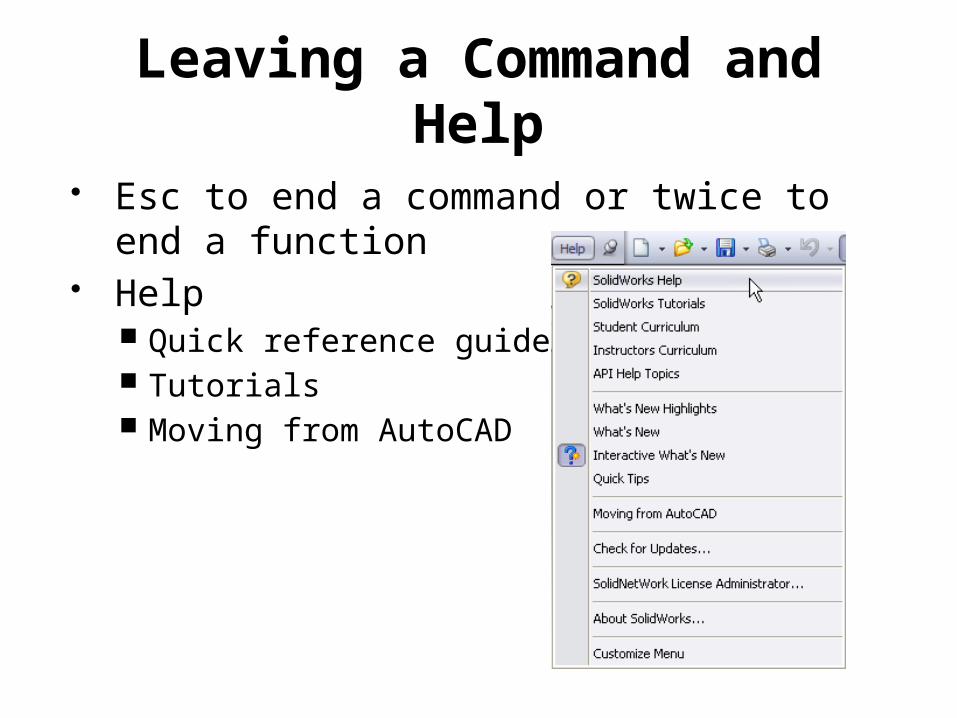
Leaving a Command and Help
Esc to end a command or twice to end a function
Help Quick reference guide Tutorials Moving from AutoCAD
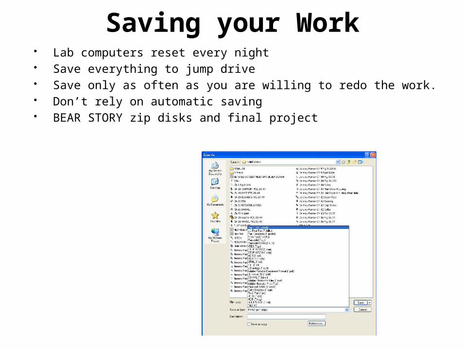
Saving your Work Lab computers reset every night Save everything to jump drive Save only as often as you are willing to redo the work. Don’t rely on automatic saving BEAR STORY zip disks and final project
Parametric Modeling Fundamentals
SOLID WORKS CHAPTER 2

Creating Rough Sketches ZEN approach (forget what you have learned) Create a sketch that is proportional to the desired shape
Concentrate on shapes and forms Keep the sketch simple
Leave out small features Fillets Rounds Chamfers
Exaggerate the geometric features of the desired shape If angle is 85˚ create at 60˚ so solid works doesn’t assume it
is 90˚ angle Draw the geometry so it doesn’t overlap
Self intersecting Form a closed region
Act as if water was inside

Parametric Modeling Steps Create rough two dimensional sketch of the basic shape of
the base feature of the design Apply/ Modify geometric relations and dimensions to the
two dimensional sketch Extrude, revolve, or sweep the parametric two
dimensional sketch to create the base solid feature of the design
Add additional parametric features by identifying feature relations and complete the design
Perform analyses on the computer model and refine the design as needed.
Create the desired drawing views to document the design

Sketch Plane 3D objects are located and defined in World
Space or Global Space Based on Cartesian Coordinate System Front Plane XY Top Plane XZ Right Plane YZ Cannot be changed or Manipulated
Local Coordinate System- relative to World Coordinate System Can be changed and manipulated

Parent-Child Relationships Constructive Solid Geometry

Solid Works Tip and Tricks F=Fit to screen Space bar = Orientation Customize Heads Up View
R click>select Rotation
Shift 90º increments Arrows 15º increments Alt + Right= clockwise View>Select Edge>Left Mouse drag
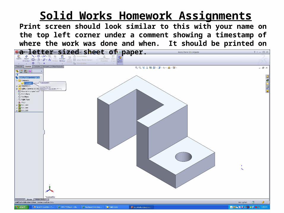
Solid Works Homework AssignmentsPrint screen should look similar to this with your name on the top left corner under a comment showing a timestamp of where the work was done and when. It should be printed on a letter sized sheet of paper.


![[Leads Generation] Use Luxify to sell luxury products online](https://img.pdfslide.net/doc/110x75/587b03d11a28ab93488b6e29/leads-generation-use-luxify-to-sell-luxury-products-online.jpg)
](https://img.pdfslide.net/doc/110x75/579054cc1a28ab900c9224d8/essential-grammar-in-use-supplementary-exercises-1996-cambridge1.jpg)