Embed Size (px)
Citation preview
Lesson 19Impedance
Learning Objectives For purely resistive, inductive and capacitive elements
define the voltage and current phase differences.
Define inductive reactance.
Understand the variation of inductive reactance as a function of frequency.
Define capacitive reactance.
Understand the variation of capacitive reactance as a function of frequency.
Define impedance.
Graph impedances of purely resistive, inductive and capacitive elements as a function of phase.
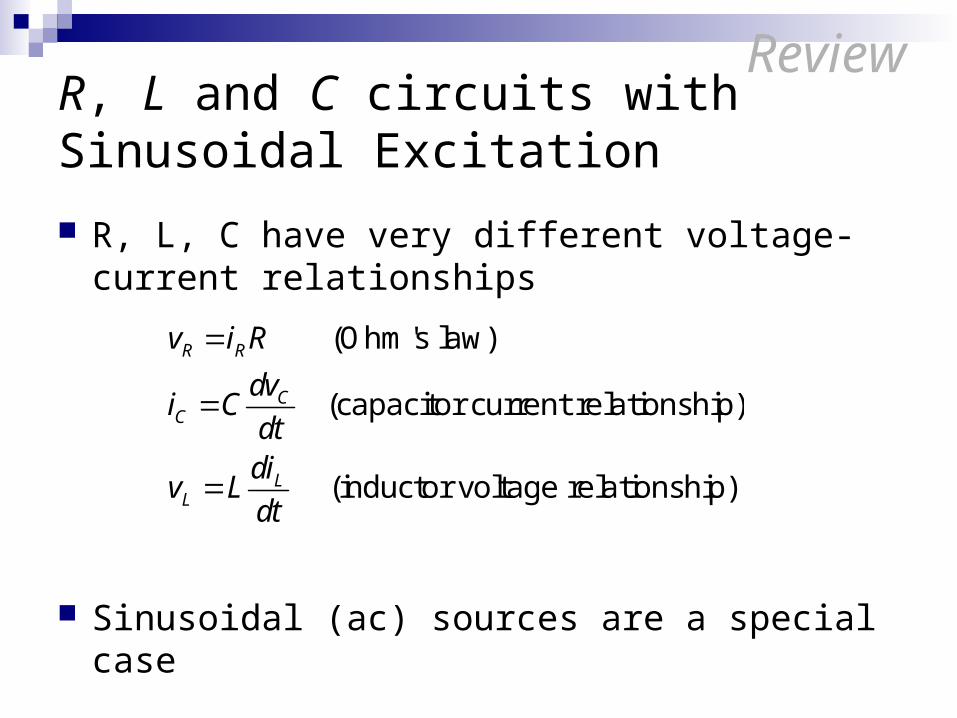
R, L and C circuits with Sinusoidal Excitation
R, L, C have very different voltage-current relationships
Sinusoidal (ac) sources are a special case
R R
CC
LL
v i R
dvi C
dtdi
v Ldt
(Ohm's law)
(capacitor current relationship)
(inductor voltage relationship)
Review
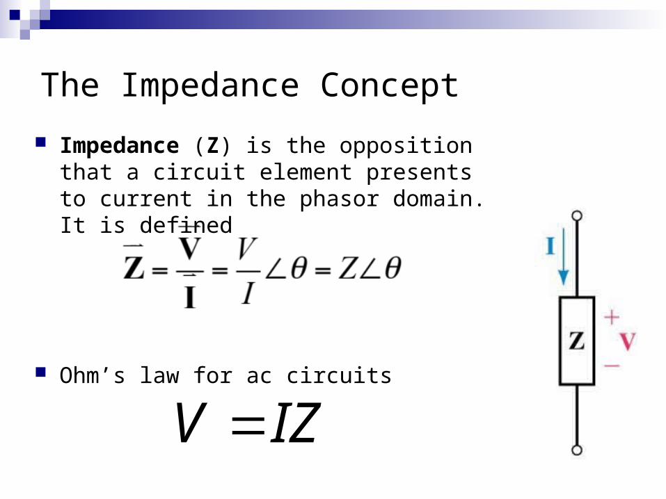
The Impedance Concept
Impedance (Z) is the opposition that a circuit element presents to current in the phasor domain. It is defined
Ohm’s law for ac circuits
V IZ
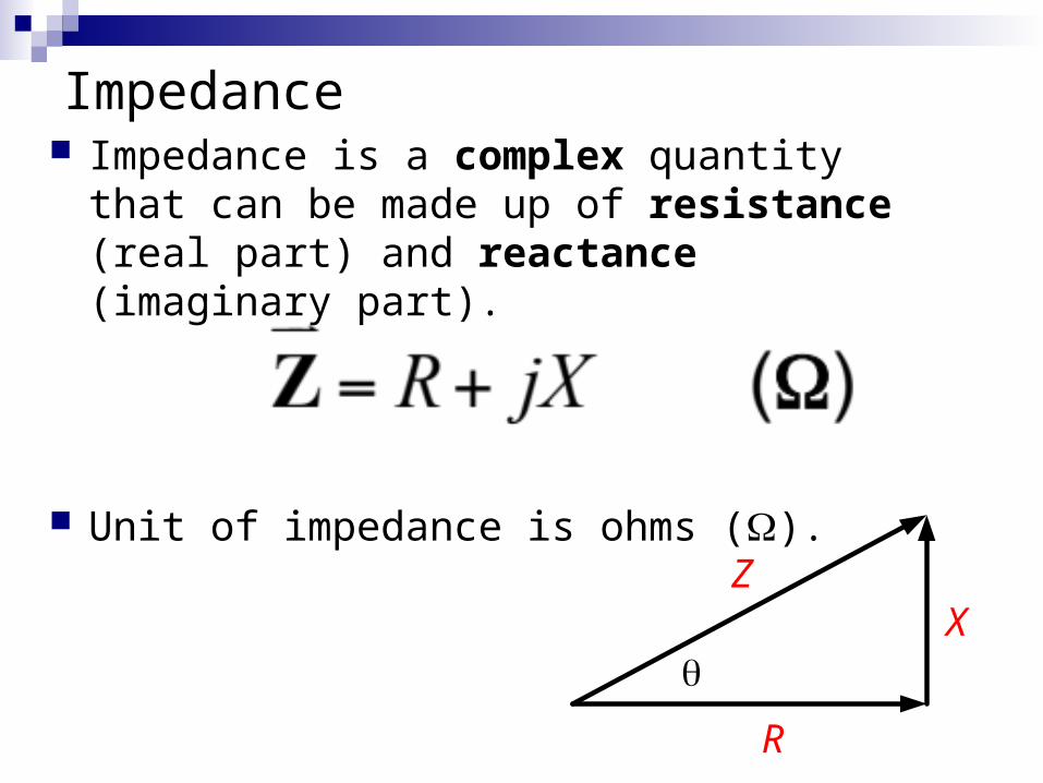
Impedance Impedance is a complex quantity that can be
made up of resistance (real part) and reactance (imaginary part).
Unit of impedance is ohms ().
R
XZ
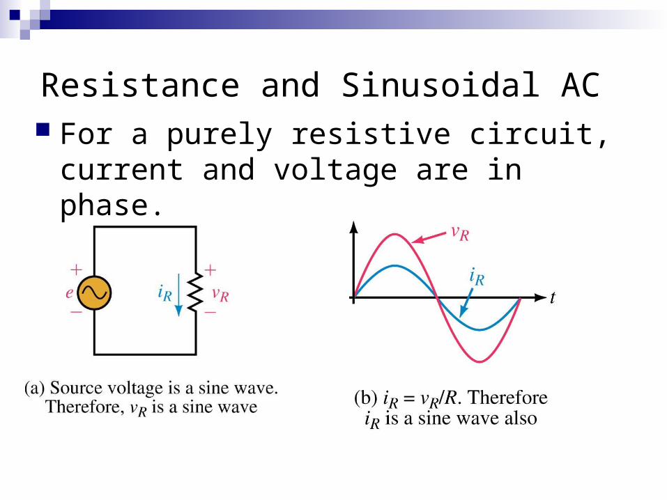
Resistance and Sinusoidal AC For a purely resistive circuit, current and
voltage are in phase.
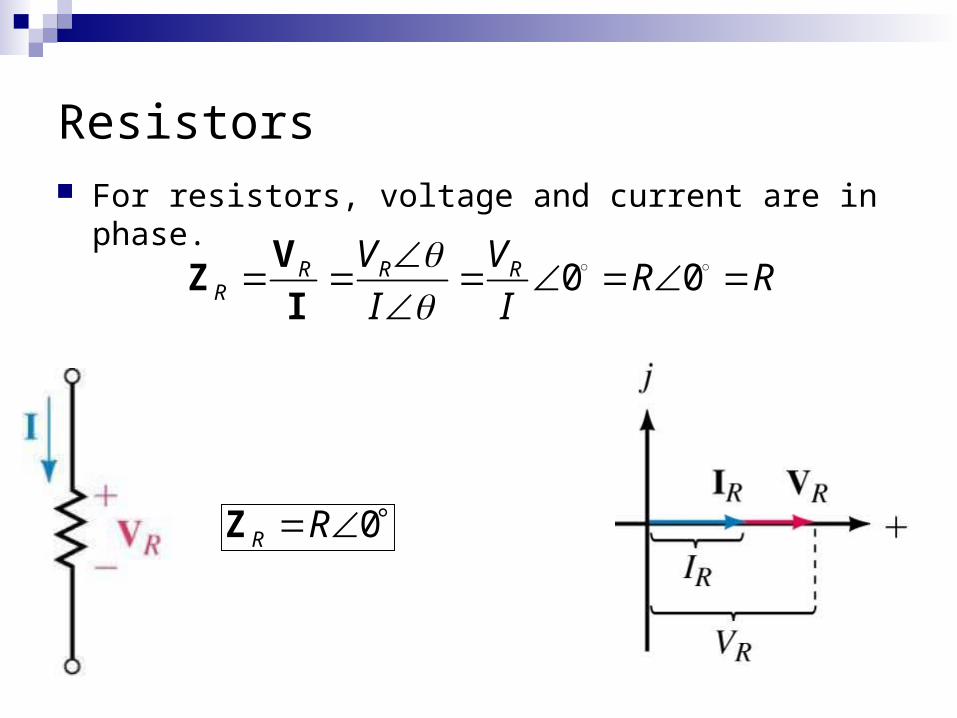
Resistors For resistors, voltage and current are in phase.
0 0R R RR
V VR R
I I
V
ZI
0R R Z
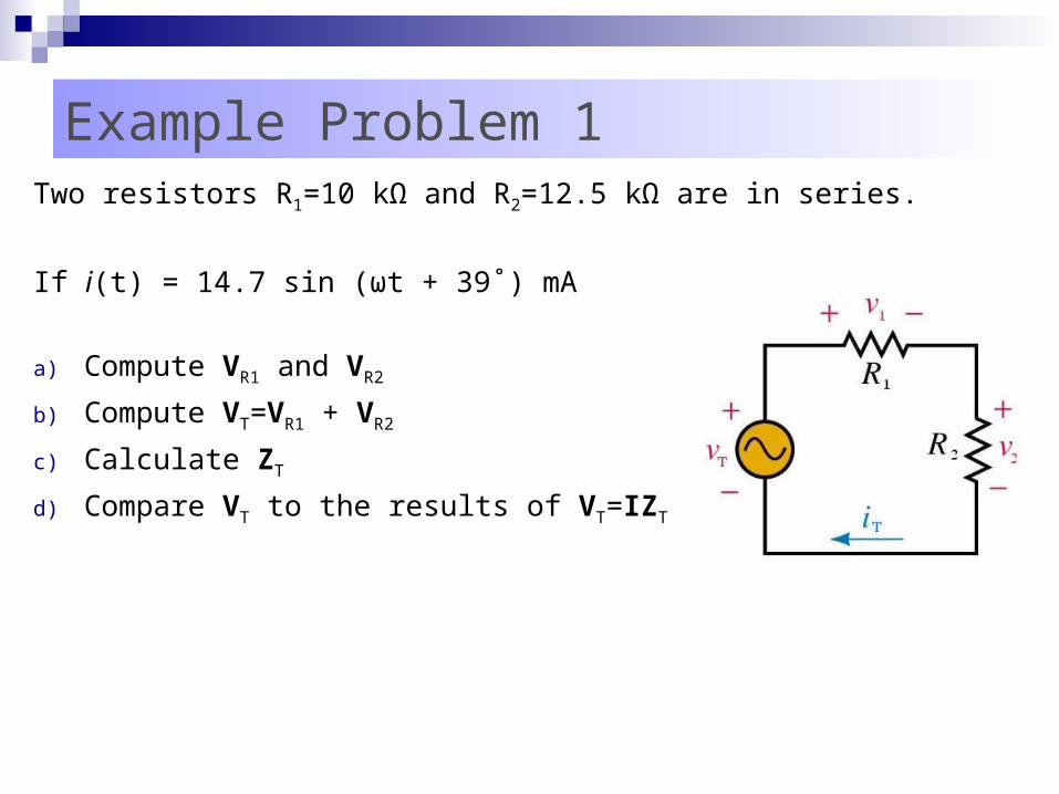
Example Problem 1Two resistors R1=10 kΩ and R2=12.5 kΩ are in series.
If i(t) = 14.7 sin (ωt + 39˚) mA
a) Compute VR1 and VR2
b) Compute VT=VR1 + VR2
c) Calculate ZT
d) Compare VT to the results of VT=IZT
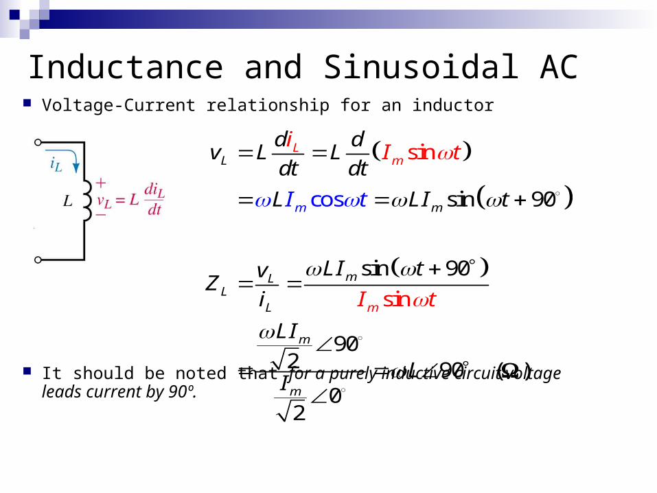
Inductance and Sinusoidal AC Voltage-Current relationship for an inductor
It should be noted that for a purely inductive circuit voltage leads current by 90º.
sin 90
sin 90
902 90
sin
s
02
co
n
s
i
L
m
mLL
L
Lm
m
m
m
m
d dv L L
dt dt
L LI t
L
I t
I tvZ
i
LI
iI t
LI
I t
( )
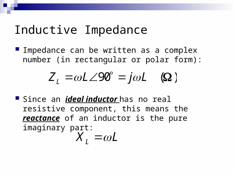
Inductive Impedance
Impedance can be written as a complex number (in rectangular or polar form):
Since an ideal inductor has no real resistive component, this means the reactance of an inductor is the pure imaginary part:
LX L
90LZ L j L ( )
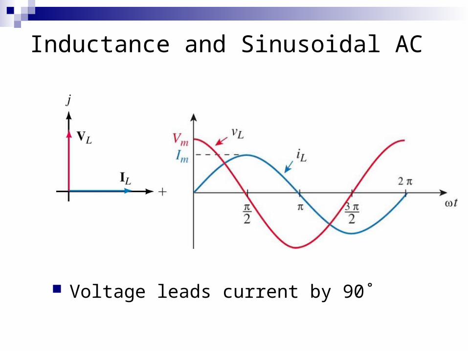
Inductance and Sinusoidal AC
Voltage leads current by 90˚
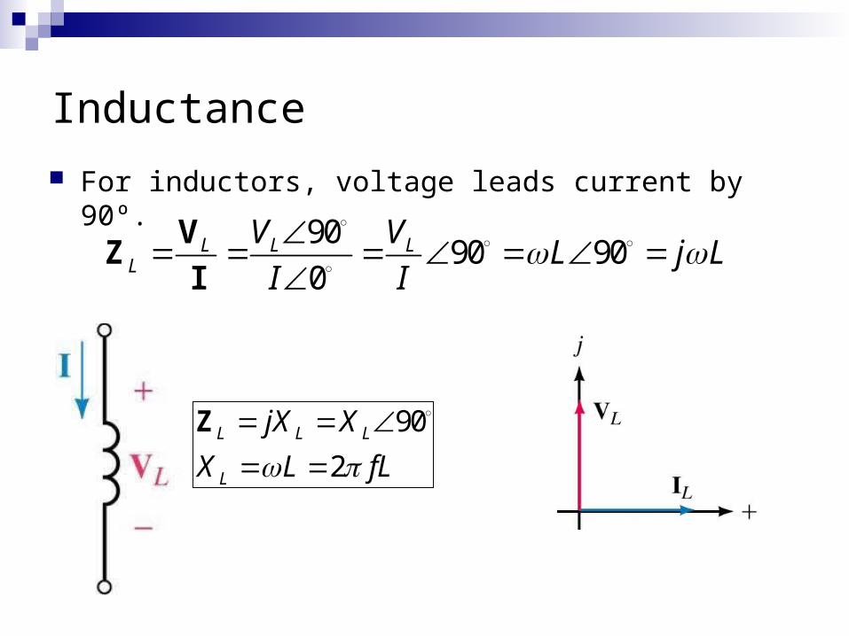
Inductance
For inductors, voltage leads current by 90º.
9090 90
0L L L
L
V VL j L
I I
VZ
I
90
2L L L
L
jX X
X L fL
Z
Impedance and AC Circuits
Solution technique1. Transform time domain currents and voltages into phasors
2. Calculate impedances for circuit elements
3. Perform all calculations using complex math
4. Transform resulting phasors back to time domain (if reqd)
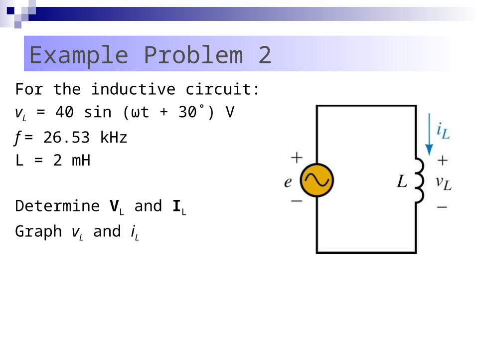
Example Problem 2For the inductive circuit:
vL = 40 sin (ωt + 30˚) V
f = 26.53 kHz
L = 2 mH
Determine VL and IL
Graph vL and iL
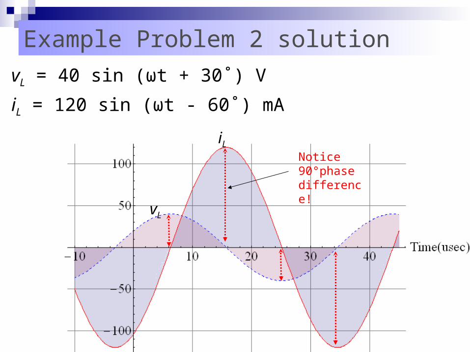
Example Problem 2 solution
vL = 40 sin (ωt + 30˚) V
iL = 120 sin (ωt - 60˚) mA
vL
iL
Notice 90°phase difference!
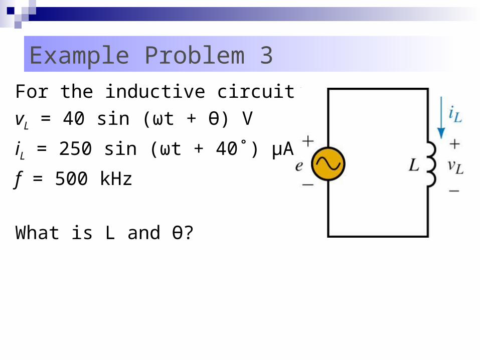
Example Problem 3For the inductive circuit:
vL = 40 sin (ωt + Ө) V
iL = 250 sin (ωt + 40˚) μA
f = 500 kHz
What is L and Ө?
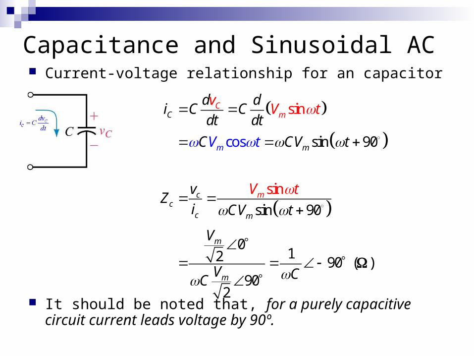
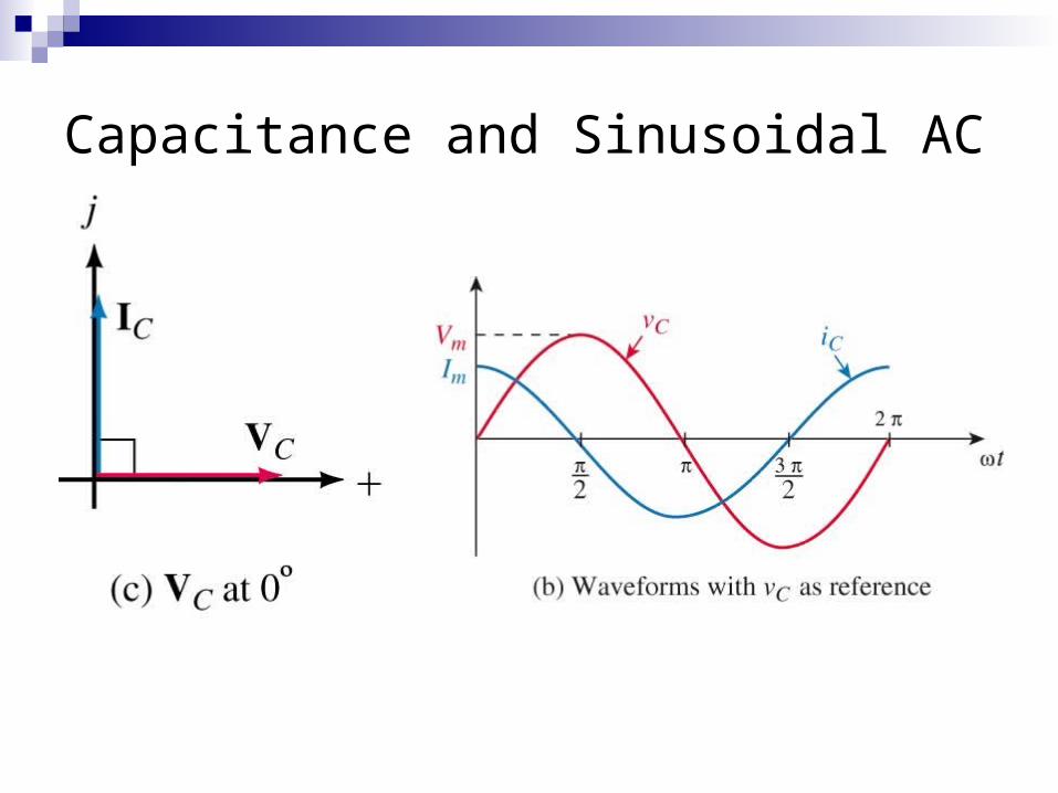
Capacitance and Sinusoidal AC Current-voltage relationship for an capacitor
It should be noted that, for a purely capacitive circuit current leads voltage by 90º.
sin
sin
sin 90
sin 90
012 90
902
cos
C
m
cc
c
m
m
m
C
m
m
m
d di C C
dt dt
C CV t
vZ
i CV t
V
V
vV t
V t
C
t
C
V
( )
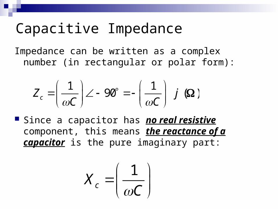
Capacitive Impedance
Impedance can be written as a complex number (in rectangular or polar form):
Since a capacitor has no real resistive component, this means the reactance of a capacitor is the pure imaginary part:
1cX
C
1 190cZ j
C C
( )
Capacitance and Sinusoidal AC
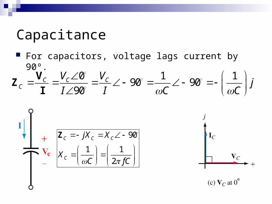
Capacitance For capacitors, voltage lags current by 90º.
0 1 190 90
90C C C
C
V Vj
I I C C
VZ
I
90
1 1
2
C C C
C
jX X
XC fC
Z
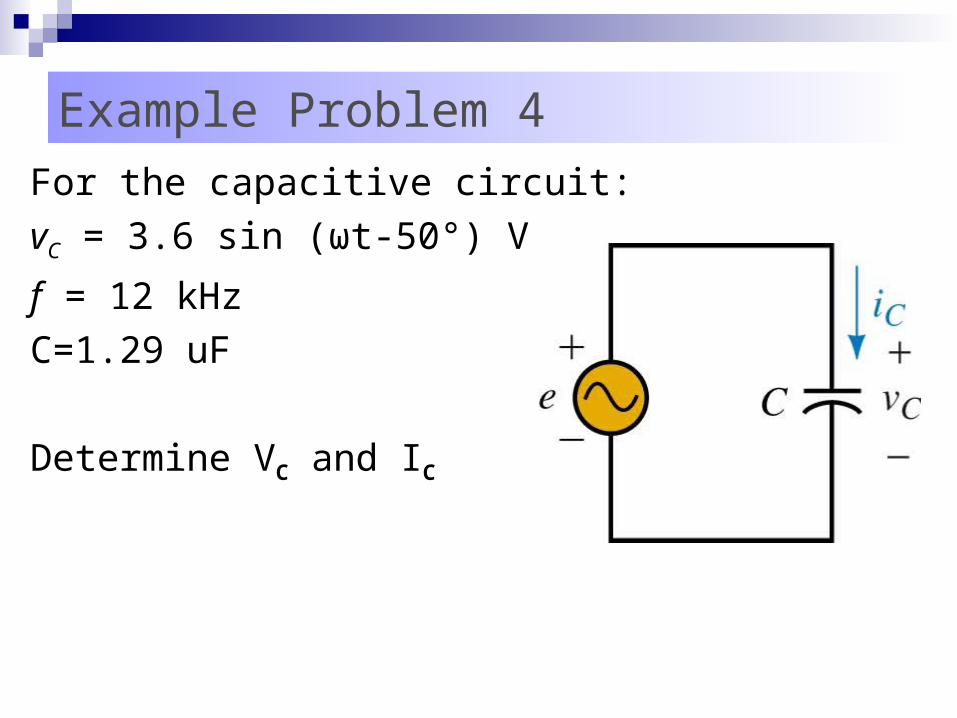
Example Problem 4For the capacitive circuit:
vC = 3.6 sin (ωt-50°) V
f = 12 kHz
C=1.29 uF
Determine VC and IC
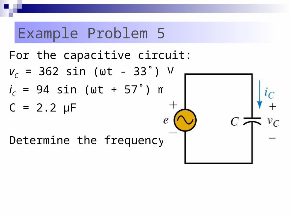
Example Problem 5For the capacitive circuit:
vC = 362 sin (ωt - 33˚) V
iC = 94 sin (ωt + 57˚) mA
C = 2.2 μF
Determine the frequency
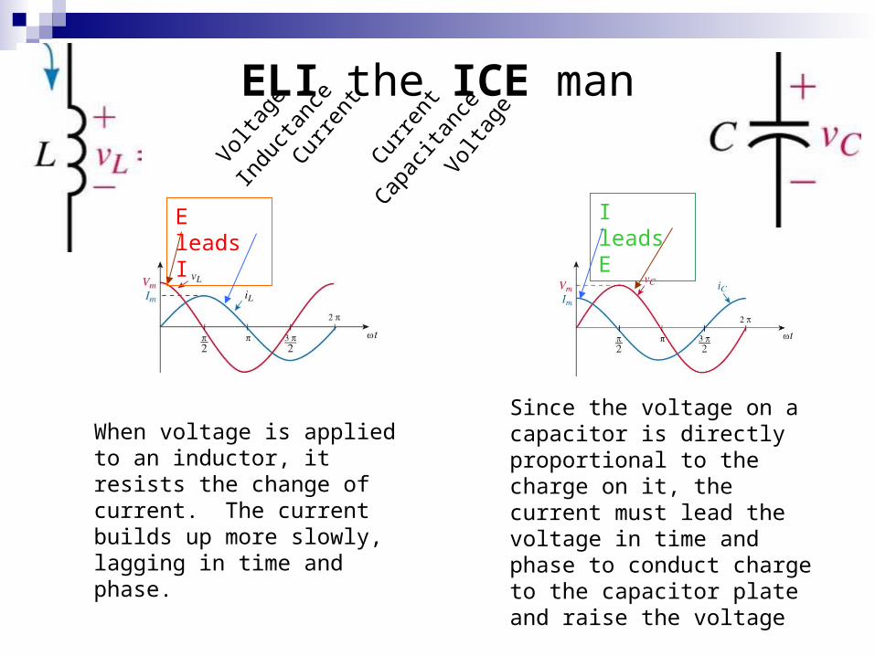
ELI the ICE man
E leads I I leads E
When voltage is applied to an inductor, it resists the change of current. The current builds up more slowly, lagging in time and phase.
Since the voltage on a capacitor is directly proportional to the charge on it, the current must lead the voltage in time and phase to conduct charge to the capacitor plate and raise the voltage
Volta
geIn
duct
ance
Curre
nt
Volta
ge
Capac
itanc
e
Curre
nt