Embed Size (px)
Citation preview

Page 1
© 2013. Siemens Product Lifecycle Management Software Inc. All rights reserved
Siemens PLM Software
1. Introduction to Laminate Composite Simulation
2. Zone-Based Process
3. Ply-Based Process
4. Modeling 3D Laminates
5. Materials and Micromechanics
6. Solution and Post-Processing
7. Laminate Theory
8. Laminate Failure Analysis
9. Laminate Dynamic Simulation
10. Laminate Optimization
Activities:
• Ply-based process on the
motorcycle mud guard
• Draping plies on a part with
undevelopable surfaces
• Exchanging ply data with
Fibersim
Lesson 3

Page 2
© 2013. Siemens Product Lifecycle Management Software Inc. All rights reserved
Siemens PLM Software
Overview of the ply-based process
Step 1: Create your mesh using shell elements.
Step 2: Set the material orientation.
Step 3: On the mesh collector, create a laminate physical property and set the stacking recipe to Inherited from layup.
Step 4: Create a global layup by:
• Creating plies and stacking them in order to achieve desired properties.
• Selecting or creating the materials best suited to your application
• Attaching the plies to the mesh or the geometry using Draping options
Step 5: Create zones.
Step 6: Validate your layup.
Step 7: (Optional) Inflate your layup.

Page 3
© 2013. Siemens Product Lifecycle Management Software Inc. All rights reserved
Siemens PLM Software
Create mesh for global layup Create 2D shell meshes using:
• 2D Mesh
• 2D Mapped Mesh
• 2D Dependent Mesh
• Commands on the Element Operations toolbar
• The resulting meshes are not associated to geometry

Page 4
© 2013. Siemens Product Lifecycle Management Software Inc. All rights reserved
Siemens PLM Software
Element Copy Operations For the non-associative Element Copy operations:
• Translate
• Reflect
• Project
Any associated layups are automatically copied
3D Inflated Elements
• You should re-generate inflated elements using the copied parent 2D elements and their copied layups

Page 5
© 2013. Siemens Product Lifecycle Management Software Inc. All rights reserved
Siemens PLM Software
Element types supported by global layups
Solver 2D Elements
NX & MSC Nastran CQUAD4, QUADR, CQUAD8, CTRIA3, CTRIAR, CTRIA6
ANSYS SHELL91, SHELL99, SHELL181, SHELL281
ABAQUS S3, S3R, S4, S4R, S4R5,S8R, S8R5, STRI3,STRI65
LS-DYNA ELEMENT_SHELL

Page 6
© 2013. Siemens Product Lifecycle Management Software Inc. All rights reserved
Siemens PLM Software
Defining laminate properties
In the ply-based process, when you assign the laminate physical property to the Mesh
Collector, you need only define options in Solver Properties and Laminate
Properties groups.
You define the following properties in the Laminate Properties group.
• Stacking Recipe
• Must be set to Inherited from layup.
• Zone Angle Tolerance
• Element zones are computed by comparing the tolerance to the relative
change in ply angles between adjacent elements.
• The finer the tolerance, the more zones (and ultimately physical properties)
will be created.

Page 7
© 2013. Siemens Product Lifecycle Management Software Inc. All rights reserved
Siemens PLM Software
Layup Modeler The Layup Modeler dialog box is the main interface used to create or modify your global plies. You can access the Layup Modeler dialog box in the following ways:
• In the Laminates tab, click Global Layup .
•
•
Choose Insert→Laminate→Global Layup.
In the Simulation Navigator, right-click the Layups node and choose New
Layup. This option is available only if a global layup already exists.
Page 8
© 2013. Siemens Product Lifecycle Management Software Inc. All rights reserved
Siemens PLM Software
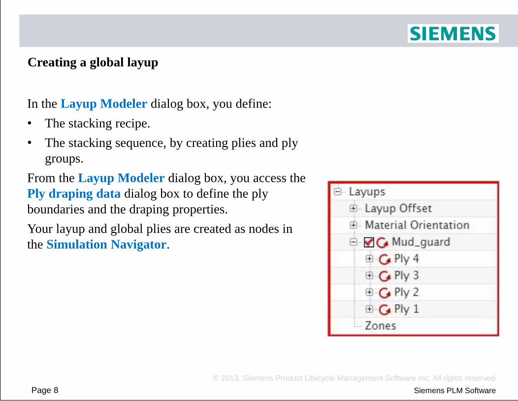
Creating a global layup In the Layup Modeler dialog box, you define:
• The stacking recipe.
• The stacking sequence, by creating plies and ply
groups.
From the Layup Modeler dialog box, you access the
Ply draping data dialog box to define the ply
boundaries and the draping properties.
Your layup and global plies are created as nodes in
the Simulation Navigator.
Page 9
© 2013. Siemens Product Lifecycle Management Software Inc. All rights reserved
Siemens PLM Software
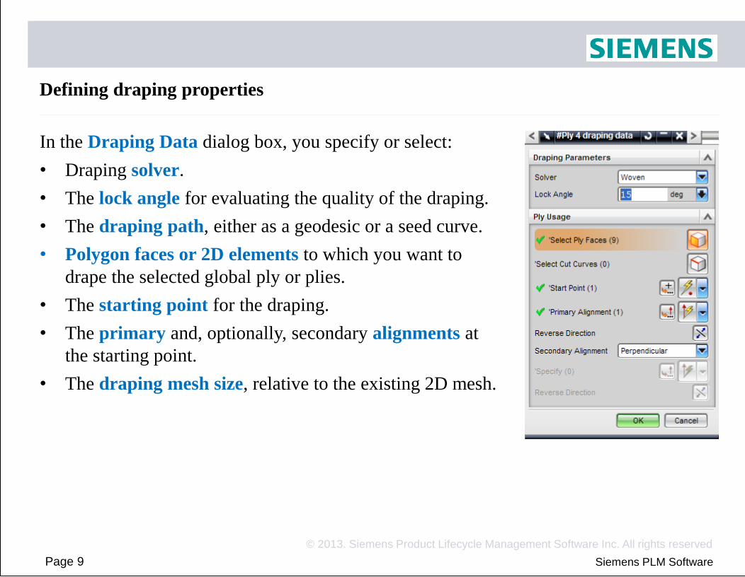
Defining draping properties In the Draping Data dialog box, you specify or select:
• Draping solver.
• The lock angle for evaluating the quality of the draping.
• The draping path, either as a geodesic or a seed curve.
• Polygon faces or 2D elements to which you want to
drape the selected global ply or plies.
• The starting point for the draping.
• The primary and, optionally, secondary alignments at
the starting point.
• The draping mesh size, relative to the existing 2D mesh.

Page 10
© 2013. Siemens Product Lifecycle Management Software Inc. All rights reserved
Siemens PLM Software
Global layups and hand layup manufacturing
The global layup approach simulates the hand layup manufacturing workflow, in
which plies of resin-impregnated unidirectional or woven fabric (1) are sequentially
positioned on a mold (2).
Plies are positioned and oriented to meet specific design requirements.

Page 11
© 2013. Siemens Product Lifecycle Management Software Inc. All rights reserved
Siemens PLM Software
Draping solvers
Woven
• Computes fiber orientation for woven pre-pregs as a function of
surface curvature.
Unidirectional
• Computes fiber orientation for unidirectional tape computed as a
function of surface curvature.
Projection
• Simply projects the material orientation onto each element.
Fiber deviation is not computed.

Page 12
© 2013. Siemens Product Lifecycle Management Software Inc. All rights reserved
Siemens PLM Software
Woven solver The woven solver computes fiber orientation for cloth woven with two sets of fibers at an angle to each other:
•
•
Warp fiber direction set by the Primary Alignment.
Weft fiber direction set by the Secondary Alignment.
The solver accommodates distortion by changing the angle (3) between warp (1) and weft (2) fibers. The fibers do not stretch. Shear angle = Original yarn angle – Distorted yarn angle

Page 13
© 2013. Siemens Product Lifecycle Management Software Inc. All rights reserved
Siemens PLM Software
Unidirectional solver
The unidirectional solver models draping of unidirectional tape, oriented using the Primary Alignment.
Neighboring fibers may slide relative to one another while maintaining the same spacing relative to one another.
The shear angle (1) is a measure of fiber slippage.

Page 14
© 2013. Siemens Product Lifecycle Management Software Inc. All rights reserved
Siemens PLM Software
Woven and Unidirectional solvers
The ply Lock Angle is a material property that specifies the maximum tolerable amount of shear, or slippage in the case of unidirectional tape
The software compares the difference between the shear angle and Lock Angle.
Green — shear angle < 90% Lock Angle
Yellow — 90% Lock Angle < shear angle < Lock Angle Red — shear angle > Lock Angle

Page 15
© 2013. Siemens Product Lifecycle Management Software Inc. All rights reserved
Siemens PLM Software
Projection solver The projection draping solver allows you to replace the zone-based process by the ply-based process, without going into the details of fiber distortion. This could be interesting for:
•
•
Preliminary design
Detailed design of parts that have simple or flat geometry

Page 16
© 2013. Siemens Product Lifecycle Management Software Inc. All rights reserved
Siemens PLM Software
Draping Domain
• For the woven and unidirectional solvers, the selected polygon faces or 2D
elements must share at least one common edge.
• For the projection solver, you can select faces or 2D elements that are not contiguous.

Page 17
© 2013. Siemens Product Lifecycle Management Software Inc. All rights reserved
Siemens PLM Software
Material orientation
Woven and unidirectional solvers
• The material orientation affects the way the zone laminate properties are
created and displayed.
• It does not change the absolute fiber orientation computed by the solvers.
• Optionally, you can set the material orientation method to Inherited from
Layup, in the Mesh Associated Data dialog.
• This allows you to map the draped fiber orientation to the Material
Orientation by specifying one ply per surface from which the data will be
taken.
Page 18
© 2013. Siemens Product Lifecycle Management Software Inc. All rights reserved
Siemens PLM Software
Material orientation
Projection solver
• The ply orientations are defined relative to the material orientation.
• To avoid a circular reference, you must not set the material orientation to
Inherited from Layup.

Page 19
© 2013. Siemens Product Lifecycle Management Software Inc. All rights reserved
Siemens PLM Software
Global layups and hand layup manufacturing
Where the draping is difficult or impossible to perform, you can:
• Define a Cut Curve:
• This allows the draping algorithm to adjust the fiber orientations independently
on the two sides of the Cut Curve.
• The structural properties of the ply are not affected.
• Cut curves are defined on 2D element edges.
• You can also manually define a ply splice:
• You can split a polygon face using modeling operations or in the fem, and
manually partition the original ply into 2 or more distinct plies.
• This will result in a discontinuity in the fiber orientation around the splice.
• You can also change the start point location, or the start direction

Page 20
© 2013. Siemens Product Lifecycle Management Software Inc. All rights reserved
Siemens PLM Software
Layup offset You set the reference plane location using the Layup Offset node.
You can define a layup offset separately for each polygon face or element selection. Layup offset nodes
• • • •
Top Middle Bottom User defined — you need to specify the Bottom Fiber Distance value.
You modify the layup offset by right-clicking the appropriate node.

Page 21
© 2013. Siemens Product Lifecycle Management Software Inc. All rights reserved
Zones
A zone is a set of 2D or 3D elements that:
• Share the same global layup.
• Have the same fiber orientations for every ply within
the specified Zone Angle Tolerance.
Each zone has a unique laminate physical property
table that is then used by the structural solver.
• For each zone, you can:
• List zone properties.
• View the layup
• Create an element group to hide, display, or make
the elements easier to select.
• Create a laminate physical property table to modify,
examine, and manage it through the Physical
Property Table Manager dialog box.

Page 22
© 2013. Siemens Product Lifecycle Management Software Inc. All rights reserved
Siemens PLM Software
Overlap and orphan elements Zones also serves as an important validation and diagnostic tool. When the solver
computes zones, the following problematic elements are shown:
• Overlap Elements
• These are the elements that are referenced by more than one global layup.
• When the draping solver encounters these elements, it issues an error in the
Information window and stops computing zones.
• Orphan Elements
• These are the elements that have a laminate physical property with the
Inherited from layup option, and that do not have a defined ply.
• When the draping solver encounters these elements, it issues a warning in the
Information window and computes zones for other elements.

Page 23
© 2013. Siemens Product Lifecycle Management Software Inc. All rights reserved
Zones and Woven Fibers
The zoning algorithm uses the primary fiber
orientations to determine zone boundaries
• For woven fibers, this is the warp orientation
For woven ply materials, you can instruct the
code to also consider the secondary, or weft,
direction.
• This allows you to more accurately account for
the deviation of both fibers in the properties
used by the solver.
If you turn on this option:
• More zones will be created
• For each zone, a new ply material will be
computed on-the-fly, with the computed weft
fiber angle
• This new ply material will be exported to the
solver as a unique orthotropic material table

Page 24
© 2013. Siemens Product Lifecycle Management Software Inc. All rights reserved
Siemens PLM Software
Display Laminate Thickness and Offset
1. Create or update zones (This is required!)
2. In the Mesh Display dialog box, select Display 2D Element Thickness and Offset.

Page 25
© 2013. Siemens Product Lifecycle Management Software Inc. All rights reserved
Siemens PLM Software
Plot Laminate Thickness Contours
1. Create or update zones (This is required!)
2. Right-click the mesh node and select Plot Thickness Contours.

Page 26
© 2013. Siemens Product Lifecycle Management Software Inc. All rights reserved
Siemens PLM Software
Activity: Ply-based process on a motorcycle mud guard
This activity introduces the ply-based process, and shows the ease
with which it supports modifications like reinforcements. The
activity will guide you to:
• Create a global layup containing the 4 base plies.
• Add a global ply to the reinforced part
of the mud guard.
• Display thickness contours. Display
element thickness and offset.
• Use the Projection draping solver.

Page 27
© 2013. Siemens Product Lifecycle Management Software Inc. All rights reserved
Siemens PLM Software
Developable and undevelopable surfaces A developable surface is a one that can be flattened onto a plane without distortion. Developable surfaces have unique flat patterns
Developable surface Undevelopable surface

Page 28
© 2013. Siemens Product Lifecycle Management Software Inc. All rights reserved
Siemens PLM Software
Developable and undevelopable surfaces Fiber distortion and shearing is present only on undevelopable surfaces. To reduce or remove fiber distortion and shearing, use:
•
•
Cut curves
Splices
Fiber orientation is important in both, developable and undevelopable surfaces.

Page 29
© 2013. Siemens Product Lifecycle Management Software Inc. All rights reserved
Siemens PLM Software
Draping solver feedback
WARNING — Bad continuity detected for ply X. Draping results could be wrong. Check element normals, slope continuity and mesh density.
In the graphics window, the regions with bad continuity between elements are highlighted. Element edges and the element normal are shown in yellow.

Page 30
© 2013. Siemens Product Lifecycle Management Software Inc. All rights reserved
Siemens PLM Software
Draping solver feedback
WARNING — Flat Pattern of plyX tears or overlaps Y times. In the graphics window, the regions where elements tear or overlap are highlighted. Element edges are shown in red. WARNING — Flat Pattern of plyX might tear or overlap Y times. In the graphics window, the regions where elements might tear or overlap are highlighted. Element edges are shown in magenta.
• These warnings are issued when the algorithm detects stretching in fibers, which
could indicate that the ply cannot conform to the undevelopable faces.
• In practice, the ply would exhibit gapping or wrinkling on the mold.
Page 31
© 2013. Siemens Product Lifecycle Management Software Inc. All rights reserved
Siemens PLM Software
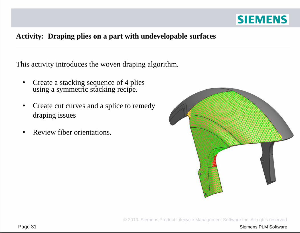
Activity: Draping plies on a part with undevelopable surfaces
This activity introduces the woven draping algorithm.
• Create a stacking sequence of 4 plies using a symmetric stacking recipe.
• Create cut curves and a splice to remedy
draping issues
• Review fiber orientations.

Page 32
© 2013. Siemens Product Lifecycle Management Software Inc. All rights reserved
Siemens PLM Software
Activity: Draping plies on a part with undevelopable surfaces
Notes • On slide 6, it can be difficult to select
the same node to define the start direction, as was used as the draping start point
• You may need to leave the cursor on top of the node, until the 3 dots appear to allow a QuickPick selection

Page 33
© 2013. Siemens Product Lifecycle Management Software Inc. All rights reserved
Siemens PLM Software
View flat pattern A flat pattern is the 2D shape that would result if you removed a ply from the mold and flattened it. For the plies draped with the Unidirectional and Woven solvers, you can:
•
•
Display the flat pattern(s).
Export the flat pattern(s) to part files.
Preview the flat pattern Part file containing the flat patterns

Page 34
© 2013. Siemens Product Lifecycle Management Software Inc. All rights reserved
Siemens PLM Software
Ply extensions
You can extend existing plies into layups other than their layup of origin.
• This allows you to simulate complex curing operations as well as the secondary
bonding process between pre-cured composite parts
Example
• In the following T-joint model, plies from the Vertical layup are extended into the
Horizontal layup.

Page 35
© 2013. Siemens Product Lifecycle Management Software Inc. All rights reserved
Siemens PLM Software
Imported layups
Use the Import Layup command to import
plies of a Fibersim ply-based laminate
(Fibersim CEE module) onto selected polygon
faces and/or 2D elements.
• After you import a layup, the imported
layup and its plies are accessible through
the Simulation Navigator.
• With the exception of the View Flat
Patterns command, you can access the
same commands for an imported layup as
for any other layup.

Page 36
© 2013. Siemens Product Lifecycle Management Software Inc. All rights reserved
Siemens PLM Software
Imported layups
How NXLC maps the Fibersim ply data to the 2D meshes in the fem:
• The Fibersim ply information is stored as a mesh of triangular elements
• When the layup is imported, NX maps the centroid of each selected 2D element
with a Fibersim triangular mesh element, using the specified tolerance, for each
ply.
• By default, NX calculates this tolerance value as the averaged NX meshed
element length.

Page 37
© 2013. Siemens Product Lifecycle Management Software Inc. All rights reserved
Siemens PLM Software
Ply import from Fibersim NX Laminate Composites reads from the Fibersim HDF5 file:
• Stacking sequence
• Fiber orientations
• Ply thickness
• Ply name
• Material name
• Material properties and units.
• Some properties, such as stress limits, may be missing
• You have a choice to override or not an existing NX material that has
the same name
• Starting point and direction of draping
• Ply angle (NX9.01)
• Rosette (NX9.01)

Page 38
© 2013. Siemens Product Lifecycle Management Software Inc. All rights reserved
Siemens PLM Software
Ply Export to Fibersim
NX Laminate Composites writes to the Fibersim HDF5 file:
• Stacking sequence
• Ply name
• By default, this is the NXLC global ply number
• If a ply description exists, it will replace the ply number
• Fiber orientations (NX 9.01)
• Only for re-import into NXLC, Fibersim does not use this data
• Material name
• Fibersim gets the ply thickness from its materials database via the material name
• Starting point and direction of draping
• 2D mesh for each ply.
• Fibersim computes ply boundaries from this mesh.
• Ply angle (NX9.01)
• Rosette (NX9.01)

Page 39
© 2013. Siemens Product Lifecycle Management Software Inc. All rights reserved
Siemens PLM Software
Assumptions and limitations when working with imported layups
• NX assumes that the draping of all plies starts from the same mold face.
• The imported layup must have been created with the same part geometry that is
meshed in NX.
• The coordinate system stored in the Fibersim file must be the same as the NX
absolute coordinate system.
• When you create a fibersim file using the Fibersim application in NX, the NX
absolute coordinate system is used by default.
• The units stored in the Fibersim file must be the same as the FEM units.
• NX reads the material property units and converts them to the FEM units.
• You cannot import an HDF5 file that you originally exported from NX, as the file
is intended for Fibersim and lacks some data necessary for NX.
• This limitation is removed in NX9.01
• You cannot import Fibersim cores.
• This limitation is partially removed in NX9.01

Page 40
© 2013. Siemens Product Lifecycle Management Software Inc. All rights reserved
Siemens PLM Software
Activity: Exchanging ply data with Fibersim
In this activity, you will:
•
•
•
Import laminate plies from Fibersim.
Modify the imported global layup.
Export the modified global layup to Fibersim.

Page 41
© 2013. Siemens Product Lifecycle Management Software Inc. All rights reserved
Siemens PLM Software
Review questions
1.
2.
3.
True/False. A developable surface is a surface that an be flattened onto a plane without distortion.
True/False. Draping in NX mimics closed molding processes such as compression molding or resin transfer molding.
True/False. For the projection solver, the selected polygon faces or 2D elements must have a least one common edge.

Page 42
© 2013. Siemens Product Lifecycle Management Software Inc. All rights reserved
Siemens PLM Software
Answers to review questions
1. True/False. A developable surface is a surface that an be flattened onto a plane without distortion.
• True. Developable surfaces have unique flat patterns that preserve the length of all paths on the surface.
2. True/False. Draping in NX mimics closed molding processes such as compression molding or resin transfer molding.
• False. Draping in NX mimics the hand layup manufacturing workflow, in which pieces of resin-impregnated unidirectional or woven fabric are individually positioned on a mold on top of each other.
3. True/False. For the projection solver, the selected polygon faces or 2D elements must have a least one common edge.
• False. For the projection solver, you can select faces or 2D elements that are not contiguous.